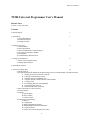
1
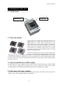
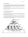
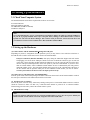
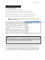
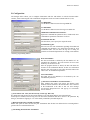
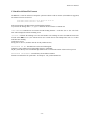
T9200 User Manual T9200 Universal Programmer User’s Manual Release Notes Version 1.0, July 14th, 2009 Contents Technical Support 2 1. Introduction 1.1 About This Manual 1.2 Product Description 1.3 Package Contents 3 2. Hardware Overview 2.1 T9200 Module 2.2 The Socket Boards 2.3 The Extended Pin Driver (EPD) Adapter 2.4 The Gang-2 and Gang-4 Adapters 2.5 N4 Adapters 2.6 Understanding USB Connection 4 3. Setting Up the Hardware 3.1 Check Your Computer System 3.2 Setting up the Hardware 8 4. Installing the Software 9 5. Tutorial for a Quick Start 10 5.1 Before Start-up 5.2 Programming Intel 28F160B3B in TSOP48 Package with Two T9200 Modules via USB Connection A. Starting up T9200 User Interface Software B. Setting up Communication with PC C. Hardware Self-Test and DRAM Test D. Assigning Site ID to Each Connected T9200 Module E. Creating a Task F. Downloading Data into T9200 Modules G. Programming Your Devices H. Protecting and Saving Your Task 5.3 Bar Code Reader to Load a Task File 5.4 Session Reports 5.5 Options A. System Option B. Device Option C. Counter Control 5.6 Serialization Programming A. History B. Configuration C. Batch Serial Data File Formats D. Running BSD Serialization on Handlers E. Compare Function F. Serial Code Generator (EasySerialize.EXE) -1- T9200 User Manual Technical Support It is often the case that users experience operating issues when installing or using a product for the first time. T9200 comes with an user-friendly Windows software to make its installation and operation an easy task. If you have questions or run into any operating issues, please consult with the following resources for help. As with other System General programmers, the latest T9200 software version with new device supports are available for downloads on the System General web sites. 1. This Manual 2. On-Line Help Press <F1> for help any time after activating the software. 3. Internet Web Site You can access either http://www.sg.com.tw (server in Taiwan) or http://www.systemgeneral.com (server in U.S.) to download the latest version of software, the device support list, and many other useful information. T9200 software contains a Demo Mode which can be executed without a connected T9200 for trainings or for evaluation purposes. 4. Your Local Distributors Check with the System General web sites to find the distributors nearest to you. 5. System General E-mail and FAX If all the above cannot resolve the operating issues please contact System General Offices at: System General Corp. (Taiwan) 8F, No. 205-3, Sec. 3, Beishin Road, Shin-Dian City, Taipei, Taiwan Tel: +886-2-2917-3005 Fax: +886-2-2911-1283 E-mail: [email protected] System General Corp. (U.S.A) 1673 South Main Street Milpitas, CA 95035 U.S.A. Tel: 408-263-6667 Fax: 408-263-6910 E-mail: [email protected] We welcome your feedback or comments to improve our products and service quality. -2- T9200 User Manual 1.0 Introduction Thank you for choosing System General T9200 universal programmer. If you encounter any difficulties using this programmer, please consult with the following resources for help (1) this manual (2) on-line help (3) your local distributors. 1.1 About This Manual This manual is served as a handy guide to help you get started quickly and acquainted with the T9200 programming system. The T9200 software contains comprehensive on-line “Help” to lead you through operational details. We suggest that you read through this manual before using the programmer and resort to the abundant Help resources embedded in the software in case of operating issues. 1.2 Product Description T9200 is a high speed universal device programmer designed to program various device technologies. Its modular design allows for production as well as engineering applications. You can start up with a single module for engineering applications. Once you are ready for mass production, up to 20 modules can be daisy-chained through their USB interface and the engineering system can be turned into a powerful production equipment. T9200 programmer needs to be connected to a PC for remote control operations. The devices supported on the system include EPROM, EEPROM, Flash EPROM, Micro-controllers, CPLD, CMOS PLD, FPGA, devices with Anti-Fuse Technologies and other devices which require custom engineering efforts. Flexibility is the design philosophy of T9200. Since each programming module is supported by an independent programming system, the programming operation on each module can take place synchronously as well as asynchronously. In addition, the programming result of one module will not have any adverse effect on other connected modules. This ensures the highest programming reliability and yields. The versatile system also supports the STAPL (Standard Test And Programming Language) and Jam languages for programming Logic devices. Its programmable parameters cover the next generation Green devices requiring 1.2 volt VCC. The high speed USB 2.0 interfaces saves you significant time on file downloading. To update the system, simply download the latest S/W and/or firmware version from System General web sites. 1.3 Package Contents When you unpack the T9200 box, you should find the followings: (1) T9200 Base Unit 1 (2) Power Cable 1 (3) USB Cable 1 (4) System Diskettes / CD (Programming Drivers) 4/1 Option: (1) Logic Devices Upgrade Pack: Supports PLD, CPLD, FPGA devices -3- T9200 User Manual 2.0 Hardware Overview 2.1 T9200 Module T9200 Module Socket Board 2.2 The Socket Boards The socket boards are designed to accommodate different device package types. It is where users place the device to be programmed into the socket. When a particular device with specific package type is selected, T9200 software will display the name of the correct socket board pertaining to the selection. Socket boards are hot-swappable. This means that the inserted socket board can be removed and replaced with a new one while the T9200 is powered on and its software system is not in the middle of executing functions. System General delivers socket boards in universal architectures as long as the related programming algorithms and the device technologies allow. When you selected a particular device in the software, the “SB Help” button will be enabled to display detailed information, including pin connections, supported devices as well as timing information. When in operation, T9200 will check if the inserted socket board matches the selected device and a warning message box will pop up, if not. 2.3 The Extended Pin Driver (EPD) Adapter The EPD adapter is an optional adapter on T9200 to further increase the number of pin drivers from the default 112 pins to 448 pins. EPD contains 336 digital pin drivers and may include other custom circuits to support custom applications. The EPD adapter designed to support Anti-Fuse Technologies is an example. 2.4 The Gang-2 and Gang 4 Adapters In addition to the single-site socket boards, the Gang-2 and Gang-4 adapters with 2 and 4 sockets respectively are available to increase the throughput for Memory programming. -4- T9200 User Manual 2.5 The N4 Adapters Besides its regular gang-programming capability, the 4-site N4 adapter was designed to program 4 NAND Flash at a time, of which each requires a different data pattern to program. The adapter comes with isolated circuitries for each socket and enhanced pin drivers to take advantage of the NAND Fast Access Mode, and is able to slash the programming time by up to 40%. With 4 sockets on the N4 adapter, this represents a 6X improvement for your NAND programming throughput. The architecture of isolated circuitries is also applicable to serial code programming. Coupled with the System General proprietary mapping technology, the N4 can serialize 4 devices at each programming cycle with minimum programming overheads. 2.6 Understanding USB Connection 2.6.1 USB Connection Topology The USB (Universal Serial Bus) interface on T9200 facilitates high speed data transfers between the PC and the programming modules as well as in between programming modules. You can download 1Gbit data file from your PC to T9200 within less than a minute! To correctly connect your T9200 modules through their USB interface, you have to understand the fundamentals of the USB bus topology. The USB physical connection is a tiered star topology. A hub is at the center of each star. The T9200 internal Hub is a 1-In, 5-Out Hub with 1-Out reserved for T9200 internal communications and other 4-Outs assigned for downstream connections. The first 9200 is in Tier 2. The limitation of tier count is 4. The figure below illustrates the topology of the 9200 USB: Host/ Root Hub Host Tier (PC) Tier 1 Hub/ 9200 Tier 2 Hub/ 9200 Hub/ 9200 Hub/ 9200 Hub/ 9200 Tier 3 Hub/ Hub/ 9200 Hub/ 9200 Hub/ 9200 9200 Hub/ Hub/ 9200 Hub/ 9200 Hub/ 9200 9200 -5- Hub/ Hub/ Hub/ Hub/ 9200 9200 Hub/ Hub/ 9200 9200 Hub/ Hub/ 9200 9200 9200 9200 Tier 4 T9200 User Manual 2.6.2 USB Host There is only one host in any USB system. The USB interface to the host computer is referred to as the Host Controller. The typical setting is to use a PC (Host Computer) with the USB interface (Host Controller) to connect to T9200 programming modules. As such, a Root Hub is already integrated within the PC system to provide one or more attachment points. 2.6.3 USB Device/Hub Since each T9200 provides programming functions to the system, it is deemed an USB device (a Node in the topology figure). If an USB device provides additional attachments points to other USB devices, such USB device is called a Hub. Each T9200 is not only an USB device but also an USB Hub which provides 4 additional attachment points to other T9200‟s. 2.6.4 Upstream and Downstream From each USB device‟s standpoint, the USB port connected to other devices in the upper tier (in a USB bus topology, see previous figure) is called upstream port. The port connected to other USB devices in the lower tiers is called downstream port. Take T9200 for instance, its back panel has one upstream port and four downstream ports. T9200 uses different connector types for the upstream and downstream ports. Upstream Input port Host (PC) Host Tier Downstream Output port Upstream Input port Downstream Hub/Dev. Downstream Hub/Dev. Upstream (Tier 2: 9200) Upstream (Tier 3: 9200) Tier 1 Tier 2 When connecting T9200 modules to the PC, be aware that the included USB cable has different connector types on both ends. Note: On the USB cable, the male connector for the Upstream connection is different from the male connector for the Downstream connection! So are the female connectors for the Upstream and Downstream connections on the back panel of T9200. Be careful to match the connector types when plug in. -6- T9200 User Manual To other upstream ports of other T9200’s in the downstream RS-232 Typically connected to a PC or the downstream port of a T9200 in the upstream USB USB DOWNSTREAM UPSTREAM M 1 0 Through the USB connection topology explained above, you can build up a huge T9200 asynchronous programming system as shown in the figure illustrated below. Host Tier/Root Hub (PC) (Two USB Port) Tier 1 (2 units) (Site #1, #2) ..4.. Tier 2 (8 units) (Site #3 ~ #10) ..4.. .. .. ..4.. ..4.. Tier 3 (32 units) (Site #11 ~ #20) ………. .. .. Site ID: When executing the T9200 PC software, you will be requested to assign a Site ID to each module connected. The PC software will present you with a list of serial numbers of all T9200 modules connected and the sequence of assigning each module an ID number is totally arbitrary. Assigning Site ID needs to be done only once, unless the connection topology of T9200 modules is changed. -7- T9200 User Manual 3.0 Setting Up the Hardware 3.1 Check Your Computer System The minimal hardware and software requirements of the PC are as below: For USB connection: Microsoft Windows 2000/XP 256 MB RAM (512MB recommend) 20 MB free disk space. Note: To use the USB interface, you are recommended to use Windows 2000 or XP. Make sure that the USB driver on your PC is properly installed. Please refer to the path: Start | Settings | Control Panel. Under it, click on System icon and select the Device Manager Tab or button. Look for the item “Universal Serial Port” and you should see two driver items available there: Host Controller and Root Hub. 3.2 Setting up the Hardware (1) Connect the PC and the T9200 modules through the USB ports Depending on your PC‟s configuration and its operation system, you may choose to use either the Serial Port or the USB interface to make connections between the PC and T9200 modules. USB port connection (Windows XP/2000): Start up by taking the USB cable shipped with each T9200 and plugging one end to the PC USB port. Watch out for the two different connector types on each end of the cable. Choose the right end that matches the USB port on your PC. Plug the other end of the cable into the USB port (labeled upstream) on the back panel of your first T9200 module. If you have more than one T9200 module, connect additional T9200 modules in such a USB hierarchy that will generate minimum number of tiers. The USB cables should run between one of the 4 downstream USB ports of the first module and the upstream USB port on each additional T9200 module you want to connect. Treat the first module as the hub to reduce the depth of the hierarchy. (2) Connect power cords between PC and T9200 modules Take the power cords in the T9200 packages and make connections between PC and all T9200 modules in which the serial port connections or the USB connections have been made. (3) Execute power-on sequence Turn on the power of the PC firstly, followed by turning on the power of each T9200 module connected. Caution should be exercised to make sure that every connected T9200 module is powered on. A connected module without being powered on may confuse the T9200 software system. (4) The hardware is ready. Note: If you have made the USB connection to a particular T9200 module, be sure to turn on its power. Should you decide to disable certain modules connected, simply disconnect their USB cables. -8- T9200 User Manual 4.0 Installing the Software 4.1 Install the Software Follow the procedures below for the software installation: Step 1: Insert T9200 software CD in your CD-ROM or unzip the downloaded software. Step 2: Use the Windows Explorer to show the content of the CD or unzip destination folder. Step 3: Select setup.exe under folder Disk1. Double click it to initiate the software installation process. Step 4: Follow the step-by-step instructions on the PC display until the installation is finished. TIP Installation procedure will install not only the T9200 software, which is T9x00.exe, but also manuals of the 9200 SKB (Socket Board) Help, Setup 9200 USB utility, Transform File utility, EasySerailization and Device Help. Step 5: (only necessary if you are using USB connection) Power off T9200 programmer(s) or disconnect the USB cable. Evoke Windows Explorer and change folder to c:\program file\system general\T9600\Driver\ and run the Set9600_2K.EXE for XP and Win2K or Set9600_98.EXE for Windows 2000 to install the USB driver in your PC. Step 6: Restart your computer to Complete the USB Driver Installation The first USB connection of each T9200 module will bring up a Found New Hardware Wizard in Window XP. Please select "Install the Software automatically". Select "Continue Anyway" in the Windows Logo Testing dialog. Then you can find "9600" in the class "Human Interface Devices" of Device Manager. Caution: If you are using the USB interface to connect the T9200 programming modules, it is mandatory to run the Setup 9600 USB utility program after the T9200 software is installed. Remember to restart your PC after this. If you forget to do so, the USB communications among T9200 modules may not function properly. Again, this is a one-time effort unless the Windows system in your PC is re-installed. Step 7: Click on the Start button at the lower-left corner of your screen again. Point your mouse to Programs | T9x00 to display respective side menus and finally click on T9x00 to launch the T9200 software. Note: Upon executing the T9200 software, the software system will automatically run the T9200 hardware selftest and the DRAM test. While these tests are recommended to ensure your hardware integrity, the software gives you an option to bypass them .For your information, it may take around 50 seconds to finish these tests. -9- T9200 User Manual 5.0 Tutorial for a Quick Start 5.1 Before Start-up Now, you have gone through the steps described in earlier sections to set up the hardware and to install the software. Check if the RS232 cables or USB cables are properly connected. Make sure that there is no device in the sockets and then turn on your PC followed by turning on all of the T9200 modules connected. Install the related socket boards on the modules, which support the algorithm and the package type of the target device. Then, you are ready to go to the next step. 5.2 Programming Intel 28F160B3B in TSOP48 Package with Two T9200 Modules via USB Connection. Reminder: Have you installed the T9200 USB Device Driver on your PC? If this is the first time you install the software, make sure that you have executed the step 5 and step 6 of "Installing the Software” commands to have the USB device drivers properly installed in your PC. A. Starting up T9200 User Interface Software Click on the Start button at the lower-left corner of your screen again, point your mouse to Start | Programs | T9x00 to display respective side menus and finally click on T9x00 to execute the software. Alternatively, you can double-click the T9x00 icon to start up! You will see the Communication Configuration dialog as shown below: TIPS: Demo and Chip List Viewer buttons can be activated as stand-alone utilities on your PC without a T9200 being physically connected. They are the perfect tools for you to practice the software and get a feeling of how the software works. Chip List Viewer becomes handy when you want to find out if a particular device is supported and, if supported, what is the part number of the related socket board. - 10 - T9200 User Manual B. Setting up Communication with PC Check the radio box on the top of the Communication dialog window shown above to tell T9200 which communication port you choose to connect T9200 to your PC. In this tutorial, check the radio box marked with “USB”. Select "9200" from "Programmer" radio box. Then, click on the Connect button to establish connections between T9200 modules and the PC. A pop-up message will remind you to remove all the devices from the sockets. After that, you are entering the remote control mode, in which the following will be displayed: C. Hardware Self-Test and DRAM Test. Right after the communication interface is selected, you will be prompted (see figure below) to decide if you want T9200 to conduct a Self-Test and an internal DRAM test. These tests could take about 50 seconds and they are recommended. An option is to press the ESC key to bypass these tests and go directly into the operation session. The menu under Options | System | Check List Options allows you to enable and disable the default setting for the Self-test and the DRAM test as shown on the dialog box below. The DRAM Test will take about 5 minutes for 8Giga bits of RAM and about 10 minutes for 16 Giga bits of RAM. - 11 - T9200 User Manual D. Assigning Site ID to Each Connected T9200 Module If this is the first time you start up the T9200 programming system, a pop-up warning message: “Site ID number(s) of the module(s) are not assigned properly” will remind you to assign a Site ID to each T9200 module in your programming system. Confirm it by OK and you will be brought to the following display. - 12 - T9200 User Manual On the left hand side of this display, the serial numbers of all the connected T9200 modules will be displayed. This window is where you are going to assign a Site ID to every T9200 module. You can request for this window display anytime by selecting the Options | System Option menu and click on Assign Site ID button under it. To enable the function for each T9200 module connected, you must assign a Site ID to each module from the beginning. Click on the serial number and you will see that the corresponding T9200 module is flashing its LED lamp to identify itself. Click on the > button to add this module to the right hand side in which the smallest available Site ID number (starting with Site ID #1) will be assigned to it. Continue this operation until you deplete all the serial numbers on the left. - 13 - T9200 User Manual It is recommended that Site ID #1 be assigned to the T9200 nearest to your PC, followed by the rest of the modules in a sequence based on their distances to the PC. Such a Site ID assignment would be the most intuitive for you to identify each module during operations. The following window will then appear to report the system configuration information. You can bring it to display any time by clicking on the SYS icon on the main menu bar. In this example, there are two T9200 modules connected and each module is mounted with a TSOP48-UNI-OT socket board. You can hot-swap the socket board as long as the software system is not in the middle of executing a function and the System Info window would detect and report such changes. As in the Assign Site ID window, you can point and click you mouse on one of the rows and the corresponding T9200 module will echo by blinking its LED on the top panel. E. Creating a Task Click on the menu item: Task | Create to establish a Task which will save the programming environments, including programming configurations, the device part number, the socket board name, system options and many other settings needed to fully resume the same programming environment at a later time. Here below is how the Task function works for the Programming Service Industry: The programming center programs the “First Articles” on T9200 and save the programming environment under a Task. The First Articles are then sent to customers for on-board tests and for other qualifications. Once the First Articles pass the qualifications and the related programming order is confirmed, the programming center can re-load the same Task on T9200 to open up the exact same environment that the First Articles were created with for mass production. By following this operation rule, the programming centers can minimize the operating mistakes caused by human errors. - 14 - T9200 User Manual Fill in the information based on your programming requirements in this create task window. For device selection, click on the Selection button to enter the following Device Select window. In Device Select windows. You can easily search for the device you intend to program as well as the required socket board to install. There are several tips which may come in handy: - 15 - T9200 User Manual (1) In the Search text input area, type in the device manufacturer‟s name followed by the part number. The onthe-fly filtering function will quickly narrow your search to the closest part number you are looking for. (2) You can narrow your search by selecting the device package type in the Socket Board drop down menu. Or, if you want to find out the list of devices which are currently supported by the installed socket boards, click on the small icon to the right of the Socket Board drop down menu. Select a device to be programmed and press the OK button to go back to the Create Task menu. After the device selection is made, click on the Next-> button to Setting Device Option as illustrated in the following window. In this window, you can define the programming flow and operations by enabling/disabling options , such as Read, Erase and Verify. For advanced applications, clicking on the Parameter button allows you to adjust the voltage settings within the legal voltage ranges of the programming algorithm pertaining to the device selection. After the device options are set, click on the Next-> button to continue on Select Data File as illustrated in the following window. - 16 - T9200 User Manual Use Browse button to select the Data File. The software will automatically detect the file format. If no data file is specified, click on the Next-> button and the following window will appear for your confirmation. You can select "Yes" to browse and select your data file. Enable the Compare checksum after Read Master or download Data File option and fill in a known checksum value. The system will calculate the checksum of the downloaded Data File or from reading the Master device and compare it with the filled-in checksum value. Tips: The SQL Connection links to MySQL database and downloads data file from a blob field. It provides a secured way to access the data file. The field names of the data table are fixed. Please contact System General for detail. Fill RAM Buffer before download: If the downloaded data file does not cover the full Memory range of the programmable device, you might want to define the unspecified data area with this feature. Multiple Binary Data Files: It provides the file-address list of combined images to facilitate your applications. Byte/Word Swap after download: To adapt to your application requirements, this feature swaps the Byte/Word sequence after the file is downloaded. - 17 - T9200 User Manual After that, click on the Next-> button to continue the Serialize process. There are two modes for the serialization software: The BSD Mode puts all the serialization codes in a text file. With the ESP Mode, you have to write an external executable and use a tagged data file to exchange information & data for each programming cycle. After that, click on the Next-> button to continue the Comment process. Now, you are almost done with the task creating routines. Click on Save & Load button in the original Create Task window to save and load the task at the same time, as shown in the following display. Right after you click on the Save & Load button, the following dialog box will appear to confirm your hardware settings. - 18 - T9200 User Manual If you have not installed any socket board on T9200 modules, it is about time you do so and ask the system to recheck the hardware. The Check again button will re-check the hardware configuration for you. F. Downloading Data into T9200 Modules After creating and loading the task as above, the system will automatically download the data file from the PC to T9200 modules. Or, if the downloading file is not defined in the Task, you can manually download a file by selecting the File | Download. Now, review all the settings shown under the tool bar of the main window, including the task name, the device part number, the manufacturer name, the socket board type and the data source. If the settings match your intention, you are ready to proceed to device programming. G. Programming Your Devices Click on the Device | Program menu or the Prog icon in the tool bar to initiate the programming operation. - 19 - T9200 User Manual The Layout tab shown at the lower right corner allows you to adjust the icon layouts. Use “Icons in one row” and “Space between rows” to design the display style you prefer. Timing Info tab shows you the averaged time spent on the programming operation and the Fail statistics tab provides you with the statistics for the causes of programming failures. Clicking on the Task Name button allows you to review of the details of the active task while the Process button is to modify the programming flow. You can choose between Synchronous and Asynchronous to program devices. Click on All Start button to synchronously start programming operations on all T9200 modules. Clicking on individual T9200 icon will activate the programming operation asynchronously on each site. H. Protecting and Saving Your Task If the programming configurations match your requirements, click on the Task | Save menu item to save the configurations and options. If you want to protect such an environment from any changes, inadvertently or maliciously, go to the Option | System Option menu and click on the Change Password button. This will lock the next software execution into the operator mode, in contrast to the Engineer mode. Under the operator mode, operators are prohibited from making changes on task setups, options and configurations. Now, you have saved the programming environment under a Task. Next time you want to program the same device with the same environment, simply load this task and you are ready to go! - 20 - T9200 User Manual 5.3 Bar Code Reader to Load a Task File You can use a Barcode Reader to read a task‟s full path filename within the double quotation marks and load the task automatically to start up the programming operations. This function was designed exclusively for Barcode Reader applications and is not applicable to the Task Manager. Note. The Bar Code Reader function will be disabled in the H9600 Mode. Code Format: "full path\taskname.ts9" For Example: "Q:\Task\SO8\SO8-150.ts9" Q&A: 1. There is a dialogue to load/edit a Task (Task Manager). But I cannot use my bar code reader in the dialogue. The Bar Code Reader function is applicable under the software‟s Main Menu only and with the Task Manager disabled. To use the Barcode Reader function, Please disable the Task Manager under: Option | System | Check List | [x] Disable Task Manager Functions Completely 2. I cannot use '\' character to create the bar code. You can use '/' instead and PUI will transfer it to '\'. 3. My full path filename is too long. I cannot put it in a single line for scanning. You can put the full path filename within double quotation marks and break the bar codes into as many lines as needed. "Q:\Task\SO8\ SO8-150.ts9" Bar Code software might insert <CR> at the line end. PUI software will ignore the <CR> and concatenate these strings. - 21 - T9200 User Manual 5.4 Session Reports After a function is executed, the PUI will log the detailed information automatically under the log folder. The system will create a YYYY-WW sub-folder denoting “year-week” to save the information. Use the path: Utilities | Session Reports to retrieve session logs. It will open the folder dialogue for you to select the sub-folder with the YYYY-WW (year–week numbers) reference. The default file name of the session log is the task file name + "-MMDD-hhmmss.ini". For example, Nu28F256EWH-0514-184807.ini Where, 'Nu28F256EWH' is the task filename, '-0514-184807‟, which denotes May 14th at 6 o‟clock 48 minute 7 second PM, is the starting time of the session. The file will be stored under C:\Program Files\System General\T9600\Log\2009-20\ folder. - 22 - T9200 User Manual 5.4 Options A. System Option Beeper: The default is "Beep if Fail", which is recommended. (The beeper will be disabled under the Handler Mode.) Message Type: The Verbose Message Type will display detailed communication messages. Job ID: This option will add "[Job ID]" to the message log before entering the Program function. You can use the <Change> button to change the Job ID name. System Setting Files: All the system options are stored in file M9.INI. The default path of M9.INI is the install path. You can change the path at the input box. Be aware that, regardless of the path change, the old M9.INI needs to be kept under the install path all the time in order to activate the new path. Generate HTML Report Files (not recommended): The HTML report feature only works with the HMI handler software for the handler model AP520. For handler models AP600, AP700 and AP800, please use the Auto Print/Auto Save/Real Time report function and select the html format under the filter feature available on the AP600 series HMI (version 1.7.0.0) to generate HTML report files. Note: To acquire a detailed Session Report from PUI, please use the new feature under: Utilities | Session Reports to access the information. A session is defined as the process of a programming function between the function‟s starting and ending time period. Session reports are generated and saved automatically by the programmer system. Assign Site ID: This configuration dialogue will pop up once a new programmer site is connected. The Handler Option provides a quick selection for the AP Series Handlers. The arrangement of site numbers is fixed on the AP Series handlers. Please avoid assigning those reserved site numbers. The detailed operation of the Assign Site ID was introduced previously on Section 5.2 D. - 23 - T9200 User Manual Change Password: The password is applicable to the Engineer Mode. Once a password was created on the previous operation, the UI will display a Mode selection and Password Input Dialogue upon re-start. Operators can skip the password input by selecting the Operator Mode under the path: Options | Operator Mode. To disable Engineer/Operator Mode, you have to input the correct "Old Password" and leave the "New Password"/"Confirm" boxes blank. "Inspection Mode (For Operator)": When Inspection Mode is enabled operators are not allowed to use Program/Erase/Secure functions. "Change Toolbar Group": The UI will group the Program/Erase/Secure tool buttons together in the toolbar and Read/Verify/Blank Check/Illegal Bit Check tool buttons will be moved to the right of the screen. Check List: [ ] Handler Mode (For AP Series Handlers): By enabling the Handler Mode, PUI will be closed due to the mode change. This will convert the manual T9200 to the handler H9200 for automated operations and those PUI-related functions like “Auto-Sense” will be disabled. Under the Handler Mode, the HMI handler software for AP520 / AP600 / AP700 / AP800 handlers can remotely control the PUI (It is a TCP/IP connection). Note: Interfaces to other SG handlers such as Gravity Handlers can be activated by purchasing H9600/H9200 programmer models and their related software upgrade kits. [ ] Show Time tag to all messages: UI will add the elapsed time to each command. [ ] Don't popup Task Manager when PUI starts: The PUI default setting is to pop up the Task Manager selection dialogue. [ ] Don't popup Task Version Warning when Load Task: On version 1.35T and after, PUI will popup a warning message if the system detects a version discrepancy between the current PUI version and the PUI version which the Task was previously created with. On Version 1.35Z and after, the software was further modified in response to the market feedback, so that PUI won't pop up this warning message until users enable this system option. [ ] Record Special Bit/Specifications info with Program function: By checking this option PUI will insert the "Special Bit"/"Parameters" information into the message log of the main window (LogC.txt). The same information will be added on session reports after version 1.35L. The purpose of the modification is to facilitate the information review on session reports. [ ] To write additional comments to "Update log buffer to Log files" Press the little Diskette button at the right-hand side of the display and a popped up "Copy log file to…" dialogue will allow you to input the destination to backup the LogC.TXT. In addition, you can write additional comments in the Note box. The added comments are usually task-related messages and will be appended to the end of the backed-up LogC.txt for future references. - 24 - T9200 User Manual Press the little Diskette Sign and confirm Yes to evoke the "Copy log files to…" dialogue. As an example, the LogC.txt is renamed as additionalC.txt, where the filename: additional.txt is user-definable. The added comments in the Note box will be appended to the end of the backed-up log files. The original LogC.txt and Log1.txt will be backed up as the changed filenames: additionalC.txt additional1.txt respectively. [ ] Also show old versions of Socket Board on Select Device display. The M-APRO HSP socket board will be displayed if the option is enabled. [ ] Operator Mode: Disable Program Function unless Verify Master Pass. With this option enabled, operators are required to pass the Verify function on the Master device(s) before proceeding to the next device programming job. [ ] Skip DRAM Test when PUI Re-Start. By default, PUI will always perform the DRAM test upon the system power-on. [ ] Always Self-Test when PUI Re-Start By default, the PIN Driver Self-test will be performed upon the system power-on. [x] Patch 9200 USB2.0 Packet for Download Checksum different issue. By default, PUI will enable this feature. - 25 - T9200 User Manual B. Device Option The default software flow is as below: 1. Insertion Check (or Auto-Sensing) 2. Pin-Continuity Check 3. Check ID 4. Blank Check | Illegal Bit Check 5. If Check Fail then Erase 6. Program 7. Verify 8. Checksum Compare 9. Secure 10. Functional Test Note. The checksum is generated from calculating the data in the system RAM Buffer. It is the result after the data file is downloaded, the data contents are modified using the Memory Editor or the checksum algorithm is re-selected. PUI will calculate the checksum automatically after those actions above are completed. Parameters… Click the “Parameters” button and an "Advanced Device Options" dialogue will pop up. The parameters are the electronic characteristics for programming the selected device, according to the device‟s programming specifications. If the values of the parameters have been manually modified for testing purposes, clicking the “Default” button will bring the values back to their default settings which are the standard settings for the target algorithm. A task can be created with default parameters, or with parameter settings which have been manually modified. However, System General strongly suggests that customers use the default parameter settings to create tasks and reserve the modified parameter settings for testing purposes only. If an algorithm needs to be modified to the extent that its default parameter settings are changed due to specification revisions or any other reasons, those old tasks created with the original default settings have to be edited or re-created with the new algorithm in order to reflect the new default settings. These parameter values will be added as a part of the Session Report. (After V1.35L) - 26 - T9200 User Manual C. Counter Control Use the "Clear" button to reset the Pass/Fail counters of a selected function. [ ] Use Target Counter Control a. PUI will display the Start Session dialogue below to allow inputting the Target Count before the Program function is started. b. PUI will add the Target Counter display at the Pass/Fail Counter area. Once the Target Counter reaches its preset number, the screen will be blinking to indicate the result and a warning dialogue "The Target Count reached! Please stop the job and exit function" will be displayed. Please note that, after the target count is reached, the system still allows operators to continue the programming operations. This feature gives the programming management an option to continue the programming operations and to exceed the target count, if the action is intended. [ ] Enable Reset Button in Functions After version 1.35Y, the software was modified to move “Reset Button” under the Counter Control function. The reason for the modification is to prevent the Reset Button from being activated accidentally by inadvertent operations especially under the automated handler mode. For manual operations, some operators might prefer keeping the Reset Button handy on the screen and this option, once enabled, will bring back the Reset Button. The default setting of this option is “disabled” (Version 1.36c and after). - 27 - T9200 User Manual 5.5 Serialization ESP: External Serialization Program. ESP is a console mode program (DOS Mode executable file). The basic command line parameters are: -Nssss –Exxxx The sequential data/information of the ESP output file is as below: T01: Current SN, Laser Text (2nd Priority) T02: Next SN T03: Format Code (Intel Hex=83,88, Motorola S=87,95 ASCII Hex=50..58) T04: Beginning of Data (Follows by Intel Hex, Motorola S, ASCII Hex data file) T05: Fatal Error T06: Limit Reached T10: Laser Text (1st Priority) Example: Run "ESP-ASCIIHex.EXE –N1 –E2000" in a DOS Box. Its output: ========================== T02:2 T01:1 T10:uP001 T03:50 T04 $AFF00, 31 30 30 30 $AFFF8, 79 86 =========================== BSD: Batch Serial Data BSD is a text file with each text line to define one set of serial number. The address-data list can be multiple for each sequential part. The data count of each address-data should not exceed 128 byte. :0001 $LuP001 $AFF00 31 30 30 30 $AFFF8 79 86 :0002 $LuP002 $AFF00 32 30 30 30 $AFFF8 BC 43 ... Address-Binary Files :0001 $L0001 $AFF00 "Files\Trunk001.BIN" :0002 $L0002 $AFF00 "Files\Trunk002.BIN" ... A. History: 1995, 2001, 2006, 2008, Multi-APRO supported ESP BSD was a backup file to store the ESP result. The function is available on the single-site socket boards only (not available on the gang socket boards). T9600 supported BSD only. The programming system provided EasySerialize.exe to generate simple BSD files. EasySerialize.exe (Serial Code Generator) supported conversions from ESP to BSD. Added ESP on T9600 as per the market demands. The Compare Function was added to the ESP algorithm. T9200 supported serialization on N4 (New 4-site) Socket Boards. The N4 Driver/Hardware supported both Set Programming and Serialization. The AP800 Handler was capable of executing Serialization on the N4 gang socket boards with high throughput. - 28 - T9200 User Manual B. Configuration: The dialogue below allows you to configure Serialization with the Task Editor or with the function under: Utilities | Serial Code Program. The serialization configuration can be saved into a T9600 Task file (*.ts9). Use BSD Mode: Use the Browse button to select the target BSD file. Use ESP Mode: Use the Browse button to select the target executable file. Additional Command Line Parameters: Input more command line parameters here, if ESP needs more command line parameters other than –N and –E. Serialization data file: The box allows you to specify the output file name. Serialization log file: PUI will save the time information regarding when ESP and command line parameters were called and executed for each serialization data. You can trace the log file to debug for possible serial number duplications or missing serial numbers caused by programming failures. First serial number: The first serial number is defined by the first number of "–N" command line parameters. PUI will increase the first serial number by one for the next call. Once the program function is started, the PUI will detect the existence of the serialization data file. If there is a serialization data file, PUI will acquire its T02 value (decimal) and use the value as the –N command line parameter. Last serial number: This input can be left undefined, or be defined by the "-E" command line parameter. [ ] First/Last serial numbers are Hexadecimal…: Once enabled, this option will convert the first/last serial numbers from the decimal to the hexadecimal. Also converted to the hexadecimal is the data at T02. An error message “EConversion Exception Error” will pop up, if a conversion error is detected. [ ] Treat T02 as next –Nttt. (Not increased by 1. Just copy T02 to ttt) By default, PUI will increase the First serial number by one and call the ESP for next sequential part. If this option is enabled, PUI will copy the T02 value from serialization data file to be next "–N" parameter. By doing so, the numeric stepping of "-N" will be totally controlled by the ESP output file. [ ] Delete data file before call ESP executable Enable this option to make sure that the prior serialization data file has been deleted before executing ESP to generate the next serialization data file. [ ] Calculating checksum after Serialization - 29 - T9200 User Manual After downloading the serialization data file, PUI will calculate the checksum before the programming is started. - 30 - T9200 User Manual Q&A: Q: How can I know those 4 starting addresses of the related memory blocks for the quad-site N4 Serialization? A: The N4 serialization algorithm will divide the system‟s 16-Gbit Memory into 4 x 4-Gbit memory blocks. From each memory block, the selected ESP or BSD algorithm executes the serialization programming on the blockrelated programming site. The serialization algorithm will automatically execute the memory division, which is unrelated to the memory size of the selected device. Therefore, the starting addresses of those 4 memory blocks have little effect on your serialization programming! Q: May I share the same BSD file among different workstations? A: Absolutely not. BSD is a text file. There is no control for multiple users. The same guideline applies to ESP, which can not use the same serialization data filename across different workstations. Q: How can I open a DOS Box easily in the selected folder? A: Microsoft provides free tools called PowerToys. The "Open Command Window Here" function comes with an "Open Command Window Here" context menu option on file system folders, which gives you a quick way to open a command window (cmd.exe) to point to the selected folder. Q: Why doesn‟t this manual contain ESP coding information or sample source codes? A: System General implements the ESP algorithm with the intention that its settings and configurations are following the operation norms and industrial standards of the device programming industry. Customers who need the ESP coding information or sample source codes for custom serialization applications have to contact System General to license the source codes, which will be dealt with on a case-by-case basis. - 31 - T9200 User Manual C. Batch Serial Data File Formats The BSD file is a text file. Please use Notepad or a plain-text editor to edit its contents. (Ultra-Editor is suggested.) The format of one line is as below: :Code-name $Ltext $Aaaaaaaa hh hh $Aaaaa hh hh hh hh :Code-name $Ltext $Aaaaaaaa “filename” Each un-used Serial Code Record starts with the leading character ':' Any text line not starting with a ':', '*', '@' or '+' character will be treated as a comment line. Code-name: It‟s a remark area. Its text starts from the leading character ':' to the first “$L” or “$A”. The Codename will be displayed on the PUI running screen. '$Ltext': It defines the marking text of the serial number. The marking text starts from $L and ends at the next $A. After HMI V1.4.9.3, the software allows user to break the text into multiple lines with “\n” to allow multi-line laser marking. Good: $Ltext1\ntext2 Wrong: $Ltext1 $Ltext (Violation: One $L file only within one line) $Aaaaaaaaa hh hh: The address area is the area following $A 'aaaaaaaa' is a Byte Address in hex digit number from 0 to 7FFFFFFF. 'hh [hh ]' is the data byte in a hexadecimal digit number from 0 to FF and the number of data can be up to 128. $Aaaaaaaaa "Filename": Load the binary file at address aaaaaaaa. Filename can include the file‟s path name. An example is: "sub_folder\test0001.bin" - 32 - T9200 User Manual D. Running BSD Serialization on Handlers The BSD file includes all serial codes for programming in one lot. The leading character ':' signifies an un-used record for a serial code. Once the serialization programming passes on PUI, the leading character ':' of the record will be overwritten by '*'. The leading character „*‟ will be further replaced by „@‟, once the device is moved to its output device, namely the tray, tape or tube output or the laser marker. Users can rely on the leading character to identify the programming status of a particular serialization record, in case that the programming operation is interrupted unexpectedly. For System General AP Series handlers, the ScanBSD function under HMI can be used to scan through the BSD file for unused serialization records. The algorithm for the ScanBSD function is that, if the number from ScanBSD is less than the keyed-in Device Count at the beginning of the session, the system will adopt the ScanBSD‟s. Comment Area: Any text line not starting with ':', '*', '@' or '+' will be treated as a comment line (remark). A text-line starting with „+‟ will be shown in the HMI ScanBSD function, which allows operators to view the information on the display. HMI ScanBSD function can revert the leading character '*' back to ':', if the related serialization programming is incomplete. Q: I use the SG Gravity Handler with H9200. Can it run Serialization? A: Yes, as long as you have purchased the software upgrade kit for your H9200. On the gravity handler, the leading characters for the BSD serialization work the same way as the BSD serialization on the desktop T9200. This means that the leading character':' will be overwritten with a '*', once its related serialization record passes the programming. - 33 - T9200 User Manual E. Compare Function: For serialized devices, the Compare function moves the data to High Memory and compares the data between each sequential device. Press the <Start> button to read the parts and generate the discrepancy list. Q: How does the compare function work on the N4 Socket Board? A: It will work the same way as the regular Read function on the N4 socket board, which is to read the device on the first enabled socket. - 34 - T9200 User Manual F. Serial Code Generator (EasySerialize.EXE): You can use the generator for simple BSD code generation. The first screen of Serial Code Generator is for the Simple Mode. The Simple Mode will generate the filename: SNData.BSD which will be saved under the install folder. Use the <Advanced..> Button at the lower-left corner to evoke the Advanced Mode. The Advanced Mode provides two methods to generate the BSD file: 1. 2. Direct BSD Method ESP Conversion Follow the step-by-step description below and the software will guide you through the BSD generation. Select "Direct BSD Method" Step 1: Buffer Declaration Step 2: Range Declaration (loop) Step 3: Data Alignment Step 4: BSD File Location Step 5: Summary and Start Q: Can 9200 accommodate both checksum and random numbers in one Serialization programming cycle? A: Yes, BSD can accommodate data with multiple address-data lists, including checksum and random numbers. However, for serialization programming with custom designs, customers have to write their own BSD generator. - 35 - T9200 User Manual Select "ESP Conversion Method" Step 1: ESP File Locations Step 2: First/Last Number (loop) Step 3: ESP Program Command Line parameters Step 4: Batch Serial Data (BSD) file Step 5: Summary and Start - 36 -