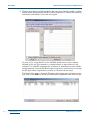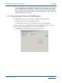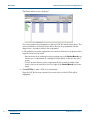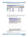
1
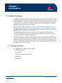
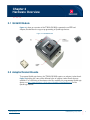
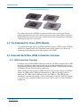
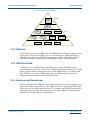
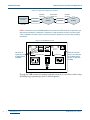
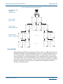
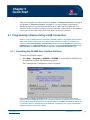
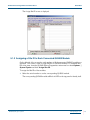
QL9600 Universal Programmer
User Manual
Contact Information
QuickLogic Corporation
1277 Orleans Drive
Sunnyvale, CA 94089
Telephone:
(408) 990 4000 (US)
(416) 497 8884 (Canada)
+(44) 1932 57 9011 (Rest of Europe)
+(49) 89 930 86 170 (Germany & Benelux)
+(8621) 6867 0273 (Asia)
+(81) 45 470 5525 (Japan)
E-mail:
[email protected]
Support:
http://www.quicklogic.com/support
Web site:
http://www.quicklogic.com/
Revision History
Revision
Date
Originator and Comments
A
May 2004
Ken Russell and Kathleen Murchek
Copyright and Trademark Information
Copyright © 2004 QuickLogic® Corporation.
All Rights Reserved.
The information contained in this document and the accompanying software programs are protected by
copyright. All rights are reserved by QuickLogic Corporation. QuickLogic Corporation reserves the right
to modify this document without any obligation to notify any person or entity of such revision. Copying,
duplicating, selling, or otherwise distributing any part of this product without the prior written consent of
an authorized representative of QuickLogic is prohibited.
QuickLogic and the QuickLogic logo, pASIC, ViaLink, DeskFab, QuickRAM, QuickPCI and QuickWorks
are registered trademarks of QuickLogic Corporation; Eclipse, EclipsePlus, Eclipse II, QuickFC,
QuickDSP, QuickDR, QuickSD, QuickTools, QuickCore, QuickPro, SpDE, WebASIC, and WebESP are
trademarks of QuickLogic Corporation.
•
•
•
•
•
•
www.quicklogic.com
© 2004 QuickLogic Corporation
Contents
••••••
Chapter 1: Introduction.............................................................................................................1
1.1. Product Overview........................................................................................................................ 1
1.1.1. Package Contents ............................................................................................................................ 1
Chapter 2: Hardware Overview ................................................................................................3
2.1. QL9600 Module ..........................................................................................................................
2.2. Adaptor/Socket Boards ...............................................................................................................
2.3. The Extended Pin Driver (EPD) Module .....................................................................................
2.4. Universal Serial Bus (USB) Connection Overview......................................................................
3
3
4
4
2.4.1. USB Connection Topology ............................................................................................................... 4
2.4.2. USB Host .......................................................................................................................................... 5
2.4.3. USB Device/Hub............................................................................................................................... 5
2.4.4. Upstream and Downstream .............................................................................................................. 5
2.4.5. Site ID ............................................................................................................................................... 7
Chapter 3: Hardware Installation .............................................................................................9
3.1. System Requirements................................................................................................................. 9
3.2. Installing the Hardware ............................................................................................................... 9
Chapter 4: Software Installation ............................................................................................ 11
4.1. Software Contents .................................................................................................................... 11
4.2. Installing the Software............................................................................................................... 11
Chapter 5: Quick Start ............................................................................................................ 13
5.1. Programming a Device Using a USB Connection..................................................................... 13
5.1.1. Launching the QL9600 User Interface Software............................................................................. 13
5.1.2. Setting Up Communication with the Computer............................................................................... 14
5.1.3. Assigning a Site ID to Each Connected QL9600 Module ............................................................... 15
5.1.4. Downloading the Data into QL9600 Modules ................................................................................. 17
5.1.5. Programming Devices .................................................................................................................... 21
5.1.6. QA/Testing the Device.................................................................................................................... 21
5.1.7. Reading the Device ........................................................................................................................ 22
www.quicklogic.com
© 2004 QuickLogic Corporation
•
•
•
•
•
•
iii
QL9600 Universal Programmer User Manual
Appendix A: Technical Support and FAQs........................................................................... 23
A.1. Technical Support ..................................................................................................................... 23
A.1. 1. Internet Web Site .......................................................................................................................... 23
A.1. 2. e-mail ............................................................................................................................................ 23
A.1. 3. Telephone .................................................................................................................................... 23
A.2. Frequently Asked Questions (FAQs) ........................................................................................ 24
iv
•
•
•
•
•
•
www.quicklogic.com
© 2004 QuickLogic Corporation
Chapter 1
Introduction
••••••
1.1 Product Overview
The System General QL9600 is a high-speed universal device programming module. The
module is designed for production as well as engineering applications through a multi-link
connectivity. You can start with a single module for engineering application and when you
are ready for mass production, the single module unit can be expanded into a powerful
production system by adding more modules.
NOTE: The System General QL9600 is same as the System General T9600, except that the
QL9600 supports QuickLogic devices only and the T9600 is a universal programmer. To modify
the T9600 for use with QuickLogic devices, obtain the Extended Pin Driver (EPD) module and the
adapters needed to program QuickLogic devices.
The QL9600 programmer(s) must be connected to a computer for remote control
operation. The devices supported on the system include Eclipse II, Eclipse Plus, Eclipse,
and certain products from the QuickPCI family.
QL9600 is designed for flexibility. Since each programming socket site is controlled and
supported by an independent programming system, the programming operation on each
module can take place synchronously as well as asynchronously. The programming result
of one module will not have any adverse effect on other connected modules. This ensures
the highest reliability and yield rate.
1.1.1 Package Contents
The QL9600 box package contents include:
• QL9600 base unit
• Power cable
• RS-232C serial port cable (9 pin)
• USB cable
• Software CD
www.quicklogic.com
© 2004 QuickLogic Corporation
•
•
•
•
•
•
1
Introduction
2
•
•
•
•
•
•
www.quicklogic.com
QL9600 Universal Programmer User Manual Rev. A
© 2004 QuickLogic Corporation
Chapter 2
Hardware Overview
••••••
2.1 QL9600 Module
Figure 2-1 shows an overview of the T9600/QL9600 connected to an EPD and
Adaptor/Socket Board to support programming of QuickLogic devices.
Figure 2-1: QL9600 Module
2.2 Adaptor/Socket Boards
To program QuickLogic devices, the T9600/QL9600 requires an adaptor/socket board.
Figure 2-2 displays the some of the different types of adaptor/socket boards that are
available. For a full listing of the adaptors that are available for programming QuickLogic
devices see http://www.quicklogic.com/home.asp?PageID=379&sMenuID=213 on the
QuickLogic website.
www.quicklogic.com
© 2004 QuickLogic Corporation
•
•
•
•
•
•
3
Hardware Overview
QL9600 Universal Programmer User Manual Rev. A
Figure 2-2: Adaptor/Socket Boards
The socket boards on the QL9600 are universal socket boards in the sense that one
specific socket will serve most of the devices that can fit in that socket. When in operation,
the QL9600 checks for the correct type of socket board in the selected device and displays
a warning message if it is not correct.
2.3 The Extended Pin Driver (EPD) Module
To program QuickLogic devices, the T9600/QL9600 requires an EPD module. The EPD
module is an optional unit for the T9600 that increases the number of pin drivers for
enhancing the programming and testing capacity of the T9600.
2.4 Universal Serial Bus (USB) Connection Overview
2.4.1 USB Connection Topology
In addition to the traditional RS232 Serial port interface, QL9600 is designed with a USB
interface to facilitate the high speed transferring of the data between the computer and
programming module as well as between programming modules. USB interface is available
for Windows 98 and 2000 operating systems only.
Figure 2-3 illustrates the topology of USB connections. To correctly connect the QL9600
modules by USB interface, follow the fundamentals of USB bus topology shown in
Figure 2-3. The USB connects USB devices with the USB host. The USB physical
interconnect is a tiered star topology. A hub is at the center of each star. Each wire segment
is a point-to-point connection between the host and a hub or node, or a hub connected to
another hub.
4
•
•
•
•
•
•
www.quicklogic.com
© 2004 QuickLogic Corporation
QL9600 Universal Programmer User Manual Rev. A
Hardware Overview
Figure 2-3: USB Connection Topology
Host Tier
Host/
Root Hub
Tier 1
Hub 1
Hub 2
Hub 3
Node
Hub 4
Node
Node
Node
Tier 2
Node
Node
Tier 3
Node
2.4.2 USB Host
There is only one host in any USB system. The USB interface to the host computer system
is referred to as the Host Controller. Use a host computer with a USB interface (Host
Controller) to connect to the QL9600 programming modules. A Root Hub is already
integrated within the computer system to provide one or more attachment points.
2.4.3 USB Device/Hub
A USB device is a unit that provides capabilities to the system. QL9600 provides
programming functions to the system so it is a USB device (a Node in Figure 2-3). If a USB
device provides additional attachment points to other USB interfaces, it is called a Hub.
Each QL9600 is not only an USB device but also an USB hub which provides four
additional attachment points to other QL9600 modules.
2.4.4 Upstream and Downstream
On each USB device, the USB port used for connecting to devices in the upper tier (see
Figure 2-4) is called an upstream port. The USB port used for connecting to USB devices
in the lower tiers are called downstream ports. For example, the QL9600 back panel has
one upstream port and four downstream ports (as shown in Figure 2-5). Upstream and
downstream ports take different connector types.
© 2004 QuickLogic Corporation
www.quicklogic.com
•
•
•
•
•
•
5
Hardware Overview
QL9600 Universal Programmer User Manual Rev. A
Figure 2-4: Upstream and Downstream Ports
Downstream
Output Port
Upstream
Input Port
Host Computer/
Root Hub
Downstream
Downstream
Hub 1/
(QL9600)
Upstream
Host Tier
Upstream
Input Port
Upstream
Tier 1
Hub 2/
(QL9600)
Tier 2
NOTE: On the back panel of QL9600 module and also on the USB interface, the upstream and
downstream connectors are different. Therefore, the two connectors on each end of the USB
cable are different also. Be careful to match the physical appearance of each when providing
connection.
Figure 2-5: QL9600 Back Panel
RS-232
Connects to
upstream ports
of downstream
QL9600s.
RS-232
USB
UPSTREAM
DOWNSTREAM
1
0
USB
Typically connects
to the host computer
or the downstream
port of an upstream
QL9600.
Through the USB connection topology explained previously, it is possible to build a large
QL9600 gang programming system as shown Figure 2-6.
6
•
•
•
•
•
•
www.quicklogic.com
© 2004 QuickLogic Corporation
QL9600 Universal Programmer User Manual Rev. A
Hardware Overview
Figure 2-6: QL9600 Gang Programming System
Host Computer Tier/
Root Hub
(2 USB Ports)
Tier 1 (2 units)
(Site 1 and 2)
..4..
Tier 2 (8 units)
(Sites 3 through 10)
..4..
..
..
..4..
..4..
Tier 3 (32 units)
(Sites 11 through 20)
……….
..4..
..4..
..
……….
..
2.4.5 Site ID
When building the QL9600 programming system (by serial port or USB connection), each
QL9600 module will be assigned a Site ID (such as Site 1) to uniquely identify itself to the
host computer. When running the QL9600 software, the programmer will be asked to
assign one Site ID to each module connected. The programmer will be presented with a
list of serial numbers for all of the QL9600 modules connected. The sequence of assigning
each module an ID number is arbitrary, and the software will automatically make sure that
Site IDs are continuous. Site ID must be re-assigned when changing the connection
topology of QL9600 modules.
© 2004 QuickLogic Corporation
www.quicklogic.com
•
•
•
•
•
•
7
Hardware Overview
8
•
•
•
•
•
•
www.quicklogic.com
QL9600 Universal Programmer User Manual Rev. A
© 2004 QuickLogic Corporation
Chapter 3
Hardware Installation
••••••
3.1 System Requirements
To connect QL9600 to a computer, the system requirements are:
• Pentium II (or higher)
• Microsoft Windows 95/98/NT/2000 for serial port
• Microsoft Windows 98/2000 for USB port
• Minimum of 64 MB RAM
• Minimum of 20 MB free disk space
3.2 Installing the Hardware
To install the hardware:
1. Connect the host computer and all QL9600 modules in the RS232 serial port or USB
port interface.
Depending on the computer configuration and operation system, use a serial port or
USB interface to make connections between the computer and all QL9600 modules.
– Serial port connection (Windows 95/98/NT/2000): Connect the computer and
QL9600 modules using the RS232 serial interface cable that comes with each
QL9600 shipment.
– USB port connection (Windows 98/2000): Using the USB cable shipped with each
QL9600 package, plug the appropriate connector into the computer USB port.
Plug the other end of the USB cable into the USB port (labeled upstream) on the
back panel of the first QL9600 module. If there is more than one QL9600 module,
connect the additional QL9600 modules using the other USB cables. Connect
them in a USB hierarchy using the least number of tiers possible. The USB cable
must be connected to one of the four downstream USB ports on the back panel of
the first module and the upstream USB port on each additional QL9600 module,
using the first module as a hub to reduce the depth of the hierarchy.
2. Connect the power cords between the computer and all the QL9600 modules.
Using the power cords in the QL9600 packages, following the previous procedure,
make connections between the computer and all QL9600 modules in which serial port
connection or USB connection has been made.
www.quicklogic.com
© 2004 QuickLogic Corporation
•
•
•
•
•
•
9
Hardware Installation
QL9600 Universal Programmer User Manual Rev. A
3. Make sure that there are no devices in the sockets, and execute the power-on
sequence.
Turn on the power to the host computer, followed by turning on the power to each
QL9600 module connected.
NOTE: Be sure that the power is turned on to every connected QL9600, otherwise the system
may not behave normally. If a module that is connected in the serial or USB interface is not in
use, disconnect the serial or USB port connection and turn off power to that module.
10
•
•
•
•
•
•
www.quicklogic.com
© 2004 QuickLogic Corporation
Chapter 4
Software Installation
••••••
4.1 Software Contents
The QL9600 software CD contains:
• QL9600 software
• QL9600 Universal Programmer User Manual
4.2 Installing the Software
To install the software:
1. Insert the QL9600 software CD in the computer CD-ROM.
2. Double-click the CD-ROM icon to show the contents of the CD.
3. Double-click on the setup.exe icon to initiate the software installation process.
4. Follow the step-by-step instructions in the installation Wizard to complete the
installation.
5. Restart the computer.
6. Select Start|Programs|QL9600 to launch the application program.
NOTE: After installing the software and selecting the communication interface to connect the
QL9600, the option is provided to perform a hardware self-test and DRAM test on the QL9600.
The self-test of the QL9600 hardware takes about 50 seconds to conduct testing on each pin
driver circuitry.
www.quicklogic.com
© 2004 QuickLogic Corporation
•
• 11
•
•
•
•
Software Installation
12
•
•
•
•
•
•
www.quicklogic.com
QL9600 Universal Programmer User Manual Rev. A
© 2004 QuickLogic Corporation
Chapter 5
Quick Start
••••••
After performing the procedures outlined in Chapter 3 “Hardware Installation” on page 9
and Chapter 4 “Software Installation” on page 11, it is time to begin programming a
QuickLogic device. If you already know what type of socket board you will need for a
particular device you want to program, you may install the socket boards on the modules
now or you can do it later after you find out what socket board you need.
5.1 Programming a Device Using a USB Connection
NOTE: If using the USB interface to connect the QL9600 modules, use Windows 98 or Windows
2000 which supports USB interface. To verify that the USB driver is properly installed in the
computer select Start | Settings | Control Panel, double-click on the System icon, select the
Hardware tab, click the Device Manager tab or button, expand the Universal Serial Bus listing.
Host Controller and Root Hub should be listed under the Universal Serial Bus listing.
5.1.1 Launching the QL9600 User Interface Software
To launch the QL9600 software:
1. Select Start | Programs | QL9600 | QL9600, or double-click the QL9600 icon
on the desktop to launch the application program.
The Communication Configuration screen is dispalyed.
NOTE: Demo and Chip List Viewer buttons can be activated as standalone utilities on the
computer without QL9600 being physically connected. They are the perfect tools for practicing
with the software and understand how the software works. Use Chip List Viewer for finding out
if a particular device is supported on the QL9600 and, if supported, what type of socket board is
needed to program that particular device.
www.quicklogic.com
© 2004 QuickLogic Corporation
•
• 13
•
•
•
•
Quick Start
QL9600 Universal Programmer User Manual Rev. A
5.1.2 Setting Up Communication with the Computer
To begin communication between the computer and the QL9600 modules:
1. Click the USB radio button connection.
If choosing a serial port connection, specify the baud rate the computer supports. The
default baud rate is 57600 bits per second. QL9600 can support up to 230400 bits
per second.)
2. Click Connect to establish connection between the QL9600 modules and computer.
3. The QL9600 will show a prompt to confirm the number of connected programmers.
– If the number of programmers is incorrect, select No and power-off the
programmers. Check all of the cables and retry.
– If the number of programmers is correct, select Yes to confirm the number of
programmers found.
A message is displayed on the screen to remove all the devices from the socket board.
4. Click OK.
The QL9600 Device Programmer screen is displayed while the system goes into selftest mode.
If this is a first-time connection between the computer and QL9600 modules, a
message is displayed stating that the Site ID number(s) of the module(s) are not assigned
properly.
5. Click OK.
14
•
•
•
•
•
•
www.quicklogic.com
© 2004 QuickLogic Corporation
QL9600 Universal Programmer User Manual Rev. A
Quick Start
The Assign Site ID screen is displayed.
5.1.3 Assigning a Site ID to Each Connected QL9600 Module
On the left side of the screen the serial numbers of all the connected QL9600 modules are
displayed. This screen is used to assign Site IDs to QL9600 modules. To renumber Site
IDs at any time, from the QL9600 Device Programmer main menu bar select Options |
System Option and click Assign Site ID.
To assign the Site IDs of the modules:
1. Select the serial number to see the corresponding QL9600 module.
The corresponding QL9600 module will flash its LED on the top panel to identify itself.
© 2004 QuickLogic Corporation
www.quicklogic.com
•
• 15
•
•
•
•
Quick Start
QL9600 Universal Programmer User Manual Rev. A
2. Click on the > button to add this module to the right side in which the smallest available
Site ID number (beginning with Site ID 1) will be assigned to it. Continue this operation
until all the serial numbers on the left are assigned.
For ease of use, assign Site ID 1 to the QL9600 module closest to the computer,
followed by the rest of the modules in a sequence based on their distances to the
computer. Use a Site ID assignment that is intuitive for identification of each module
during operations. Once the site IDs have been assigned, it is not necessary to re-assign
the IDs again unless programmers are added or removed from the setup.
The System Info screen is displayed. To view system configuration information at any
time, click on the SYS icon on the QL9600 Device Programmer main menu tool bar.
16
•
•
•
•
•
•
www.quicklogic.com
© 2004 QuickLogic Corporation
QL9600 Universal Programmer User Manual Rev. A
Quick Start
In this example, there is one QL9600 module and one T9600 module, each mounted
with a QT-SG-PQ208 socket board. If a socket board is hot-swapped with another
type, the System Info screen will detect and report the change. As in the Assign Site
ID screen, select one of the rows and the corresponding QL9600 module will echo by
blinking its LED on the top panel.
5.1.4 Downloading the Data into QL9600 Modules
The QL9600 module requires two things to program a QuickLogic device:
• A device driver that is used to program the device.
• A LOF file that contains a set of design links that are to be programmed.
There are several ways to download the data into the QL9600 modules, but for the
purpose of this quick start guide, only one way will be described.
1. Click Load on the QL9600 Device Programmer main screen.
© 2004 QuickLogic Corporation
www.quicklogic.com
•
• 17
•
•
•
•
Quick Start
QL9600 Universal Programmer User Manual Rev. A
The Device Select screen is displayed.
This screen enables the programmer to select the LOF file and the device driver. The
screen will default to a listing all of the devices that can be programmed with the
adaptor that is currently inserted in the programmer.
In Device Select screen the programmer can search for the device to program and the
required socket board to install.
– Narrow the search by selecting the device package type in the Socket Board drop
down menu, or alternatively by selecting the device family on the left side of the
screen.
– To find out what devices can be programmed by the currently installed socket
boards, click on the small icon just to the right of the Socket Board drop down
menu.
2. Click LOF File to select a LOF to be downloaded.
Once the LOF file has been selected, the correct driver for that LOF file will be
highlighted.
18
•
•
•
•
•
•
www.quicklogic.com
© 2004 QuickLogic Corporation
QL9600 Universal Programmer User Manual Rev. A
Quick Start
3. Click OK to confirm the driver and LOF file download.
The selected LOF file and highlighted driver will be downloaded at the same time.
The status of programming sites screen is displayed. Confirm the hardware settings and
verify that the board has been installed properly.
4. If the correct socket boards are not already installed, install the correct socket boards
on the QL9600 modules.
5. Click Check again to recheck the hardware configuration.
© 2004 QuickLogic Corporation
www.quicklogic.com
•
• 19
•
•
•
•
Quick Start
QL9600 Universal Programmer User Manual Rev. A
6. If everything is correct, click Confirm.
A message is displayed on the screen to remove all the devices from the socket board.
7. Click OK.
Before the data is downloaded to the programmer it will do a self-test and then prompt
the programmer to enter the foundry lot and job numbers.
8. Type the foundry lot and job numbers (optional).
These numbers will be displayed on the programming summary files.
9. Click OK to each to continue with the download.
Once the LOF file has been downloaded successfully, the QL9600 Device Programmer
screen is displayed.
From this screen the user can program units, QA, read the silicon signature, or load an
alternative LOF file.
20
•
•
•
•
•
•
www.quicklogic.com
© 2004 QuickLogic Corporation
QL9600 Universal Programmer User Manual Rev. A
Quick Start
5.1.5 Programming Devices
To program the devices:
1. Click on Program.
The Program Function screen is displayed.
2. Click on Task Name to review details about the active task.
3. Click Close.
4. Conduct the programming operation in a Synchronous or Asynchronous mode.
Click on All Start to synchronously start programming operation on all of the
QL9600 modules, or click on an individual QL9600 module icon to activate the
programming operation in that site.
5.1.6 QA/Testing the Device
The QA screen looks similar to the Programming Function screen. Use this screen to
perform a similar test at the end of programming to ensure that the devices are good.
© 2004 QuickLogic Corporation
www.quicklogic.com
•
• 21
•
•
•
•
Quick Start
QL9600 Universal Programmer User Manual Rev. A
5.1.7 Reading the Device
The Read Device screen looks similar to the Programming Function screen. Use this screen
to read the silicon signature of the devices. The silicon signature will display the following
details of the device:
• Design Checksum
• File Checksum
• Programmer Vendor (indicates the type of programmer used to program the parts)
• Software Revision
• Date Programmed
• Status
NOTE: In gang mode, once the silicon signature has been read, moving the mouse over a
programmer or clicking on the appropriate site tab will display the details for the device in that
programmer.
22
•
•
•
•
•
•
www.quicklogic.com
© 2004 QuickLogic Corporation
Appendix A
Technical Support and FAQs
••••••
A.1 Technical Support
There are many options for technical support when installing and using the QL9600.
These consist of the internet web site, e-mail, and telephone support. A brief breakdown
of the resources and how to access them is listed below.
A.1.1 Internet Web Site
QuickLogic Software and Devices: www.quicklogic.com/support
You can access http://www.quicklogic.com/software download to download the latest
version of QL9600 software. QL9600 software contains a demo mode, which can run
independently for practice or evaluation purposes.
A.1.2 e-mail
QuickLogic Software and Devices: [email protected]
A.1.3 Telephone
USA - Technical Hotline: (408) 990-4100
Europe - Hotline: +44-1932-57-9011
www.quicklogic.com
© 2004 QuickLogic Corporation
•
• 23
•
•
•
•
QL9600 Universal Programmer User Manual Rev. A
A.2 Frequently Asked Questions (FAQs)
The following is a list of Frequently Asked Questions for the QL9600 module.
Question: What versions of Windows are supported?
Answer: For serial port interface, Microsoft Windows 95, 98, NT, and 2000.
For USB port interface, Microsoft Windows 98 and 2000.
Question: What is a Site ID?
Answer: A Site ID is an identification code that is used to refer to or identify a particular
QL9600 module in a multi-linking configuration. Similar to assigning a name to each
connected module. All the software log and messages refer to the QL9600 module by its
uniquely assigned Site ID instead of its serial code. For ease of use, assign Site ID 1 to the
QL9600 module closest to the computer, followed by the rest of the modules in a sequence
based on their distances to the computer. Use a Site ID assignment that is intuitive for
identification of each module during operations.
Question: How do I deal with devices in other packages?
Answer: Use socket boards. A socket board is essentially an adapter to connect QL9600
pin driver signals to the device under programming.
Question: How do I know if a particular device I need to program is supported or not?
Answer: QL9600 software is equipped with a demo mode which allows it to run in
standalone mode. You can try it out and also learn what socket board you will need to
program a particular device.
Question: Should I connect the QL9600 to the computer in USB or serial interface?
Answer: QuickLogic recommends the use of the USB due to higher performance
download speeds. However, without regard to download speeds, it does not matter
whether you choose the USB or serial port to connect the programmer to your computer.
Question: What are Tasks?
Answer: Tasks enable a user to marry a device driver and LOF file together. Once created
the user can simply download a task rather than having to select both the device driver and
the LOF file to be downloaded. To create a task, select Task|Create Task from the main
screen.
Question: Where can I get the new software updates?
Answer: QuickLogic’s download page at www.quicklogic.com/software_download.The
demo software is the best source to view the chip list.
24
•
•
•
•
•
•
www.quicklogic.com
© 2004 QuickLogic Corporation
QL9600 Universal Programmer User Manual Rev. A
Question: Why does it take so long to download the LOF file when I am using USB?
Answer: USB can handle transfer speeds of up to 12 Megabits per second. However, the
bottleneck is in the downloading of the LOF file due to the QL9600 interpreting the LOF
data and writing it to memory, giving an overall transfer rate of 0.2 Megabits per second.
For example, a 10 MB LOF file should download in less than 7 minutes to a single
QL9600.
Question: Why does my computer take excessively long to download a LOF file?
Answer: USB competes for the use of the CPU; if you are running another application
that is processor intensive, the download rate will be adversely affected. To ensure shortest
download times, any processor intensive applications should be closed before starting the
QL9600. Note that closing the offending application during the download will not enable
the QL9600 transfer rate to speed up as it remains at the same rate. For best results use
a dedicated machine for programming.
Question: Who do I contact if I think if have low yielding or bad hardware?
Answer: Contact QuickLogic’s Application Support at
http://www.quicklogic.com/support or 408-990-4100.
Question: How do I do a Return Material Authorization (RMA)?
Answer: Contact QuickLogic’s Application Support at
http://www.quicklogic.com/support or (408) 990-4100 and speak to them about the
problems you are seeing. If it is obviously the hardware failing, go to System General’s web
site at http://www.systemgeneral.com/ or http://www.sg.com.tw/ and file a RMA.
© 2004 QuickLogic Corporation
www.quicklogic.com
•
• 25
•
•
•
•
QL9600 Universal Programmer User Manual Rev. A
26
•
•
•
•
•
•
www.quicklogic.com
© 2004 QuickLogic Corporation