1
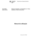
OY1P303P0102 OY1P303P0189 Transit Time Sensor for Measuring Tasks Operating Instructions Status: 17/01/2013 EN 2 Table of Contents 1. Use for Intended Purpose 4 2. Safety Precautions 2.1. Safety Precautions 2.2. Laser/LED warning 4 4 4 3. EC Declaration of Conformity 4 4. Device Features 4.1. Connecting the Sensors 4.2. Housing Dimensions 4.3. Control Panel 4.4. Complementary Products 5 6 7 7 8 5. Mounting instructions 8 6. Initial Operation 6.1. Initial Operation 6.2. Default Settings 8 8 9 7. Functional Overview 7.1.Run 7.2. Pin Function 7.3. Function of E/A1 and E/A2 7.3.1. Switching Output Foreground Teach-In 7.3.2. Switching Output Background Teach-In 7.3.3. Switching Output Window Teach-In 7.3.4. Switching Output Poti 7.3.5. Switching Output Hysteresis 7.3.6. Switching Output Window Size 7.3.7. Switching Output NPN/PNP 7.3.8. Switching Output NO/NC 7.3.9. Switching Output Response Time Delay 7.3.10. Switching Output Fall Time Delay 7.3.11. Switching Output Pulse Length 7.3.12. Switching Output Teach-In External 10 12 12 13 14 14 15 16 16 16 16 17 17 17 18 18 EN 7.4.Analog 7.5.Display 7.5.1. Display Mode 7.5.2. Display Intensity 7.6. Expert Menu 7.7. Offset 7.8. Filter 7.9. Laser 7.10.E/A Test 7.10.1. E/A Test – Test A1 or A2 7.10.2. E/A Test – Test Ana U or I 7.11.Interface 7.11.1. Mode Interface 7.11.2. Baud Rate Interface 7.11.3. ASCII Interface 7.11.4. Interval Interface 7.11.5. Mask Interface 7.12.Language 7.13.Info 7.14.Reset 7.15.Password 3 19 19 19 20 20 20 22 23 23 23 23 24 24 24 24 25 25 28 28 28 29 8. More Settings via the RS-232 Interface 8.1. Control via a terminal program 8.2. Remote Control with Interface Commands 29 30 31 9. Maintenance Instructions 31 10. Proper Disposal 31 EN 4 1. Use for Intended Purpose The transmitter and the receiver are integrated into a single housing. The Sensors measure the distance between the Sensor and the object. They function in accordance with the principle of transit time measurement. For this reason, the object‘s color, shape and surface characteristics have practically no influence on measurement results. Even dark objects can be reliably recognized against bright backgrounds. Large working ranges and distances are achieved by these Sensors. The Sensors work directly onto the object. 2. Safety Precautions 2.1. Safety Precautions ••This operating instruction is part of the product and must be kept during its entire service life. ••Read this operating instruction carefully before using the product. ••Installation, start-up and maintenance of this product has only to be carried out by trained personal. ••Tampering with or modifying the product is not permissible. ••Protect the product against contamination during start-up. ••Not a safety component in accordance with the EU Machinery Directive. 2.2. Laser/LED warning Class Laser 1 (EN 60825-1) LASER CLASS 1 Observe all applicable standards EN60825-1 and safety precautions. 2007 3. EC Declaration of Conformity The products are developed, constructed and manufactured according to the directive 2004/108/EC. The following international standards and specifications apply: EN 60947-5-2:2007 EN 60825-1: 2007 Low-voltage switchgear and controlgear, Part 5-2: Control circuit devices and switching elements – proximity switches Safety of laser devices Any additional standards which are applicable for the given application must be observed. RoHS EN 5 4. Device Features OY1P303P01 Order Number Working Range Measuring Range Reproducibility Linearity Deviation (200…3050 mm) Linearity Deviation (50…200 mm) Switching hysteresis Light Source Laser Class Supply Voltage Current Consumption (Ub = 24 V) Switching Frequency Response Time Temperature Drift (–10° < Tu < 50°) Temperature Drift (Tu < –10°) Temperature Range Voltage Drop Switching Output/Switching Current Short Circuit Protection Reverse Polarity and Overload Protection Protection Class Protection Connection Suiting Connection Technology No. Connection Diagram No. Interface IO-Link version 89 02 50...3050 mm 3000 mm 1 mm 7 mm 15 mm 3 – 20 mm Laser light (red) 1 18…30 V DC < 70 mA 250 Hz 2 ms < 0,2 mm/K < 0,4 mm/K – 40 °C…50 °C < 2,5 V 100 mA yes yes III IP68 M12 × 1; 8-pin M12 × 1; 4-pin 89 2 531 782 RS-232 IO-Link — 1.0 Measuring Range: The Sensors’ measuring range is determined by object remission. Maximum range of up to 3 m on white (90 % remission) up to 3 m on grey (18 % remission) up to 2 m on black (6 % remission) Light Spot Diameter Working Distance Light Spot Diameter 0 5 mm 3m 9 mm EN 6 Dependence of Hysteresis and reproducibility on the Sampling Rate on white (90 % Remission) OY1P303P01xx Default setting for min. hysteresis in mm 20 16 12 10 8 6 5 4 3 Set Filter 1 2 Default Settings 5 10 20 50 100 200 500 Reproducibility in mm 15 10 8 6 5 4 3 2 1 Power-on Drift The following table provides information on the power-on drift during the warm-up phase. Time in min Power-on drift in mm 0 ±7 1 ±5 2 ±4 5 ±2 10 ±0 4.1. Connecting the Sensors OY1P303P0189 OY1P303P0102 531 782 EN 7 4.2. Housing Dimensions 1 = Transmitter Diode 2 = Receiver Diode 4.3. Control Panel Po1 X2 60 23 20 22 20 = Enter Button 22 = Up Button 23 = Down Button 60 = Display 02 01 68 01 = Switching Status Indicator 02 = Contamination Warning 68 = Supply Voltage Indicator EN 8 4.4. Complementary Products wenglor offers Connection Technology providing field wiring means. Suiting Mounting Technology No. 380 Suiting Connection Technology No. 2 89 S02 S74 IO-Link Master Protection Housing Set ZSP-NN-02 Protection Housing Set ZSV-0x-01 5. Mounting instructions During operation of the Sensors, the corresponding electrical and mechanical regulations, as well as safety regulations must be observed. The Sensor must be protected from mechanical impact. The Sensor has optimal ambient light characteristics if the background changes within the Working Range. 6. Initial Operation 6.1.Initial Operation Before the configuration, connect the Sensor to 18…30 V DC. The desired menu language must be selected after initial start-up, and after each reset (see fig. 1). Fig. 1: Set menu language The functions of the keys appear in the display as follows: 5 : Navigate up. 6 : Navigate down. : Selection is acknowledged with the enter key. The keys within a menu item can also be assigned to letters or other symbols such as “+” and “–”. You can keep the “+” or “–” key pressed for a longer time in order to make larger numerical jumps. EN 9 Meaning of the menu items: 3Back: one level higher in the menu. 7Run: switch to delay mode. Switch to the configuration menu by pressing any key. Note: If no settings are adjusted in the configuration menu for a period of 30 s, the Sensor is automatically returned to the read-out view. The Sensor accesses the last used menu view when a key is once again activated. If a setting is adjusted, it becomes active when the configuration menu is exited. Important: Do not use any sharp objects to press the keys when configuring settings, because they might otherwise be damaged. 6.2. Default Settings Pin Function Outputs Analog Display Expert menu Offset Filter Laser Interface Language Password E/A 1 E/A 2 Teach Mode Switching threshold Switching Hysteresis Window Size PNP/NPN NO/NC On-Delay Off-Delay Impulse U/I 4 mA 20 mA Mode Intensity Specification Offset OY1P303P0102 Switching output Analog output T Foreground 1000 mm 12 mm 50 mm PNP NO 0 ms 0 ms 0 ms I 50 mm 3050 mm Switch Screensaver Off 0 mm 5 On Mode Baud Rate ASCII Interval Mask Enable Enter English Off OY1P303P0189 Switching output Switching output T Foreground 1000 mm 12 mm 50 mm PNP NO 0 ms 0 ms 0 ms I 50 mm 3050 mm Switch Screensaver Off 0 mm 5 On Comm 38400 Binär 10 ms 1 English Off EN 10 7. Functional Overview Switch Error Contaminate Analog** Laser Ext T Ax Offset*** Run E/A1 E/A2 Pin Function Depends on pin function E/A1: A1 Switch A1 Error A1 Contaminate E1 Laser E1 Ext T A2 E1 Offset If Switching Output Depends on pin function E/A2: A2 Switch A2 Error A2 Contaminate A2 Analog E2 Laser E2 Ext T A1 E2 Offset If Error Output or Contamination Output T Foreground T Background T Window Poti Hysteresis Window size* NPN/PNP Display Expert Menu Value in mm Value in mm Value in mm PNP NPN Pushpull NO/NC NO NC ON Delay OFF Delay Impulse T Extern Value in ms NPN/PNP NO/NC Analog Press <T> for Teach-In Value in ms Value in ms T Foreground T Background T Window PNP NPN Pushpull If Input Ub Ub active inactive If analog Output* Mode U/I Teach-In At 0 V* At 10 V* At 4 mA* At 20 mA* Select U or I Mode Rotate Intensity Switch Analog ON OFF Menu items that are presented in bold are always displayed in the menu. The other menu items appear only when the Expert Menu is activated. * Visibility depends on the selected settings (see details in the respective section) ** can only be selected for E/A2 in OY1P303P0102 *** only for OY1P303P0189 Measuring Range Teach-In Value in mm Value in mm Value in mm Value in mm Min Normal Max Power save Screensaver EN Offset*** Filter Laser 11 T for Teach-In Z for Value set to 0 Preset Change Apply 1 2 5 Value in mm T for apply Z for disable 10 20 50 100 200 500 ON OFF Depends on pin function E/A1 and E/A2: E/A Test Test A1 Test A2 Test Analog Test E1 Test E2 Mode Baude rate Interface (only OY1P303P0189) ASCII Interval Mask Language Deutsch English Francais Espanol Italiano Info Display order number and Sensor version Reset Press <R> for Reset Password Enable Change Lock *** only for OY1P303P0189 ON, OFF ON, OFF Value in V resp. I Run Mode Input Menu Comm Const 9600 38400 115200 Binar ASCII Value in ms No. for Mask ON, OFF Password: 0 – 9999 Run-Run Mode EN 12 The following explains the functions behind the individual menu items. 7.1. Run The Sensor switches into display mode. Selected pin function E/A1 (E/A2) with respective status Bar graph display of the current measured value relative to the measuring range A1 AN 1500 mm Current measured value in mm The set function of the pins is symbolically shown as follows: AN Analog output A1 A2 A3 Switching output A1 or A2 F Error output V Contamination output La Laser shut-off E Offset input Teach input for A1 or A2 7.2. Pin Function The Pin Function serves to determine the function of the pins E/A1 or E/A2. The pins can each take on different functions. E/A1 Switch Error Contaminate Laser Ext T A2 Offset 3 Back 7 Run E/A2 Switch Error Contaminate Analog Laser Ext T A1 Offset 3 Back 7 Run Configuration of pin E/A1 Switch: Switching output Error: Error output Contaminate: Contamination output Laser: Input for switching the transmission light on and off Ext T A2: Teach input for A2 Offset: Offset input (visible only at OY1P303P0189 if Expert menu is “On”) Configuration of pin E/A2 Switch: Switching output Error: Error output Contaminate: Contamination output Analog: Analog output (for OY1P303P0102) Laser: Input for switching the transmission light on and off Ext T A1: Teach input for A1 Offset: Offset input (visible only at OY1P303P0189 if Expert menu is “On”) The pin E/A2 can only be set as an analog output for Sensor OY1P303P0102. Sensor OY1P303P0189 already has a permanently set analog output (see connection diagram). EN 13 7.3. Function of E/A1 and E/A2 Depending on the pin function that has been set, the selected name is displayed for the menu item, e.g., A1 Switch or E1 Laser. The menu items each contain the following sub-items: For switching output If the pin is set as a switching output, the following functions can be set: A1 Switch/A2 Switch T Foreground T Backgrnd T Window T Extern Poti Hysteresis Window size NPN/PNP NO/NC ON Delay OFF Delay Impulse 3 Back 7 Run Sensor settings for switching outputs T Foreground: Teach-In from object T Backgrnd: Teach-In from background T Window: Teach-In from window in which the Sensor switches T Extern: Define Teach mode for external Teach-In Poti: Recalibrate the switching point Hysteresis: Change the difference between the switch-on and the switch-off points Window size: Change the distance between the two switch-off points NPN/PNP: Configuration of the output NO/NC: Configuration of the output ON Delay: Response time delay (only visible if Expert menu “On”) OFF Delay: Fall time delay (only visible if Expert menu “On”) Impulse: Pulse length (only visible if Expert menu is “On”) These menu items will be described in more detail in chapters 7.3.1 to 7.3.12. For error or contamination output If the pin is set as an error or contamination output, the following functions can be set. A1 Error (Example) NPN/PNP NO/NC 3 Back 7 Run A1 or A2 as an error or contamination output NPN/PNP: Configuration of the output NO/NC: Configuration of the output You can find explanations of “NPN/PNP” in chapter 7.3.7 on page 16. You can find explanations of “NO/NC” in chapter 7.3.8 on page 17. For Laser Switch-off, Extern Teach and Offset input If the pin is used as an input, e.g., for switching off the laser. It is possible to set whether the input is active at Ub or at 0 V. E1 Laser (Example) Ub active Ub inactive 3 Back 7 Run Setting E1 or E2 Ub active: The input is activated if the supply voltage (Ub) is present Ub inactive: The input is activated if no voltage is present EN 14 7.3.1. Switching Output Foreground Teach-In Teach-In is performed while the sensor spot is aligned to the object. The switching distance is then automatically set to a distance which is slightly greater than the clearance between the sensor and the object. The sensor is thus activated for all objects whose distance to the sensor is equal to or less than the distance to the object used for the Teach-In procedure. Sensor Teach Distance Switching Point Object T Foreground Press <T> for Teach-In Foreground Teach-In Teach-In Foreground process 1) Align light spot to object. 2) Press “T” key. The switching point is learned. Note: ••The switching point can be recalibrated in the menu item Poti (see chapter 7.3.4 if needed. ••The switching hysteresis can be modified in the menu item Hysteresis (see chapter 7.3.5) if needed. 7.3.2. Switching Output Background Teach-In Teach-In is performed while the sensor spot is aligned to the background. The switching distance is then automatically set to a distance which is slightly less than the clearance between the sensor and the background. The sensor is thus activated whenever an object is located between the background and the sensor. Sensor Teach Distance Object Switching Point EN 15 T Backgrnd Press <T> for Teach-In Background Teach-In Teach-In Background process 1) Align light spot to background (e.g., on conveyor belt). 2) Press “T” key. –> The switching point is learned. Note: • The switching point can be recalibrated in the menu item Poti (see chapter 7.3.4) if needed. ••The switching hysteresis can be modified in the menu item Hysteresis (see chapter 7.3.5) if needed. 7.3.3. Switching Output Window Teach-In In case of the Window Teach-In there are two switching points. The difference between the two switching points is referred to as a window. The size of the window is referred to as window width. The sensor is activated when an object is positioned within the window. Sensor Teach Distance Switching Point 1 Window Width Object T Window Press <T> for Teach-In Switching Point 2 Window Teach-In Teach-In Window process 1) Align light spot to foreground (if present) or to object. 2) Press “T” key. –> The switching points are learned. Note: ••The Window Size variable can be increased or decreased in the menu item Window (see chapter 7.3.6). 50 mm is the preset. ••The center of the window can be readjusted in the menu item Poti (see chapter 7.3.4) if needed. The two switching points are alternately displayed in this process. ••The switching hysteresis can be modified in the menu item Hysteresis (see chapter 7.3.5) if needed. Examples of applications: Ex. 1: Recognition of objects that are very difficult to recognize visually, e.g., shiny black metal plates in an extremely slanted position in front of a background. –> Use Teach-In Background for this application. Ex. 2: Distinction of objects, e.g., small and large packages on a conveyor belt. –> In this application, use Teach In to the object to be recognized, at which the Sensor is to switch. EN 16 7.3.4. Switching Output Poti Potentiometer Switching point in mm Vary switching point The switching point can be manually varied by pressing the “+” or “–” keys. You can keep a key pressed for a longer time in order to make larger numerical jumps. 7.3.5. Switching Output Hysteresis The switching hysteresis is the difference between the switch-on and the switch-off points. Hysteresis Hysteresis in mm Vary hysteresis The hysteresis can be increased by pressing the “+” key. The hysteresis can be reduced by pressing the “–” key. The minimum hysteresis depends on the filter that has been set (see chapter “4. Device Features” on page 5). You can keep a key pressed for a longer time in order to make larger numerical jumps. 7.3.6. Switching Output Window Size Note: The menu item is only visible if a Window Teach has been conducted. Window size Window size in mm Vary window size The window size can be increased by pressing the “+” key. The window size can be reduced by pressing the “–” key. The minimum value that can be set is 10 mm. You can keep a key pressed for a longer time in order to make larger numerical jumps. 7.3.7. Switching Output NPN/PNP NPN/PNP PNP NPN Pushpull 3 Back 7 Run Configuration of the outputs PNP: The load or the evaluation device is connected between the negative pole (reference) and the output. When switched, the output is connected via an electronic switch to the positive pole. NPN: The load or the evaluation device is connected between the positive pole (reference) and the output. When the Sensor switches, the output is connected via an electronic switch to the negative pole. Pushpull: Push-pull output. Functions like an electronic switch that selectively couples the output to the positive pole or the negative pole EN 17 7.3.8. Switching Output NO/NC NO/NC NO NC Configuration of the outputs The output is set as a normally open contact by pressing the “NO” key. The output closes immediately when an object reaches the switching point. The output is set as a normally closed contact by pressing the “NC” key. The output opens immediately when an object reaches the switching point. 7.3.9. Switching Output Response Time Delay The response time delay is an adjustable lengthening of the response time. Object Output ON Delay Note: The menu item is only visible if Expert Menu “On” has been set (see chapter 7.6 on page 20). ON Delay ON Delay in ms Adjust response delay time An output time delay of 0 to 10,000 ms can be set by pressing the “+” or “–” key. You can keep a key pressed for a longer time in order to make larger numerical jumps. 7.3.10. Switching Output Fall Time Delay The fall time delay is an adjustable lengthening of the fall time. Object Output OFF Delay Note: The menu item is only visible if Expert Menu “On” has been set. OFF Delay OFF Delay in ms Adjust fall time delay A fall time delay can be set by pressing the “+” or “–” key. You can keep a key pressed for a longer time in order to make larger numerical jumps. Note: If a pulse length has been set, a fall time delay cannot be set In this case the note “Pulse” appears in the control panel! EN 18 7.3.11. Switching Output Pulse Length The pulse length defines how long the switching state is held. The function can be combined with a response time delay. Object Impulse Pulse combined with ON Delay Pulse Length ON Delay Pulse Length Note: The menu item is only visible if Expert Menu “On” has been set. Pulse Pulse length in ms Set pulse length A pulse length of 0 to 10000 ms can be set by pressing the “+” key or the “–” key. You can keep a key pressed for a longer time in order to make larger numerical jumps. 7.3.12. Switching Output Teach-In External The teaching mode that the switching output is to have can be defined in this menu. Following a signal on a pin that has been set as the external teaching input for this switching output, a Teach-In is conducted in the set teaching mode. T Extern T Foreground T Backgrnd T Window 3 Back 7 Run Teaching Mode for External Teach-In T Foreground: Foreground Teach-In T Backgrnd: Background Teach-In T Window: Window Teach-In EN 19 7.4. Analog The “Analog” menu item is always present with Sensor OY1P3030189. The menu item “A2 Analog” is present for the Sensor OY1P303P0102 if pin 2 is set as an analog output. Analog Mode U/I Teach-In At 0 V At 10 V At 4 mA At 20 mA 3 Back 7 Run Settings of the analog output Mode U/I: Set analog output to a voltage or current output.. The analog output can be set as a voltage output by pressing the “U” key. and as a output by pressing the “I” key. Teach-In: Teach-In of the start and end of the measurement range, depending on the U/I mode set. By pressing the “T” key, the current distance is assigned the value 4 mA or 0 V. The value 20 mA or 10 V can be assigned to a distance by navigating downwards. The smallest measurement range that can be set is 50 mm. At 0 V: Distance at 0 V (visible in U mode) The distance assigned to the value 0 V can be recalibrated by pressing the “+” key or the “–” key. At 10 V: Distance at 10 V (visible in U mode) The distance assigned to the value 10 V can be recalibrated by pressing the “+” key or the “–” key. At 4 mA: Distance at 4 mA (visible in I mode) The distance assigned to the value 4 mA can be recalibrated by pressing the “+” key or the “–” key. At 20 mA: Distance at 20 mA (visible in I mode) The distance assigned to the value 20 mA can be recalibrated by pressing the “+” key or the “–” key. 7.5. Display Display Mode Rotate Intensity 3 Back 7 Run Adjusting the display device Mode: Select display mode (see chapter 7.5.1) Rotate: Rotate display by 180°. The display is rotated by 180° by pressing the key. The rotation is canceled by pressing this key again. Intensity: Set the display intensity (see chapter 7.5.2) 7.5.1. Display Mode Mode Switch Analog 3 Back 7 Run Select display mode Switch: The statuses of the individual inputs and outputs, and the measurement value in mm are shown in the display. Analog: The analog output value and the measurement value in mm are shown in the display. EN 20 7.5.2. Display Intensity Intensity Min Normal Max Power save Screensaver 3 Back 7 Run Set the display intensity Min: The intensity of the display is set to a minimum value. Normal: The intensity of the display is set to a medium value. Max: The intensity of the display is set to a maximum value. Power save: The display switches off after one minute without a button being pressed and automatically switches back on when a button is pressed. Screensaver: The colors of the display are inverted every minute. 7.6. Expert Menu Different menu items and sub-items appear in the menu, depending on whether the Expert Menu is “On” or “Off”. The Expert Menu is off in the delivery state. The menu is thereby shorter and easier to use. If the existing menu items are not sufficient for the application solution, the Expert Menu can be switched on in order to use the full scope of Sensor functions. Expert Menu OFF ON 3 Back 7 Run Switch Expert Menu on or off OFF: The Expert Menu is switched off and only a few menu items are visible. ON: The Expert Menu is switched on and all menu items are visible. 7.7. Offset The Offset function is used to change the current measurement value to a defined value. The switching thresholds and the analog measurement range are also changed. Note: The menu item is only visible if Expert Menu “On” has been set. The menu item can only be selected in OY1P303P0189. Offset Preset Change Apply 3 Back 7 Run Change the measurement value Preset: Learn offset value. The current measurement value is adopted as the offset value specification by pressing the “T”. The offset value is set to 0 by pressing the “Z” key. Change: Change the value of the offset. By pressing the “+” key or the “–” key, the value set in the “Specification” menu item can be changed. Apply: Accept the offset value set in the menu item “Specification” as the measurement value. By pressing the “T” key, the offset value set in the menu item “Specification” is adopted as the displayed measurement value. The Offset function is reset by pressing the “Z” key, and the actual distance is displayed. The currently set offset value is displayed in mm. The offset can also be applied (Offset –> Apply –> T) via the pin E1 or E2, if it is set as the offset input (see chapter “7.2. Pin Function” on page 12). In order to use the offset it is necessary to apply a voltage > 7 V to the input pin. EN 21 Example of the measurement value and switching point for the Offset function: a) Without Offset: In the diagram, the Sensor measures a distance of 500 mm. The switching point is located 200 mm distant, at 700 mm. Object Switching Point Switching Distance 700 mm 500 mm 700 mm Actual Distance b) With Offset: In the diagram, the Sensor measures a distance of 500 mm. After application of the offset with offset value of 0 mm, the measurement value at 500 mm becomes the measurement value 0 mm. Thereby the actual distance of the switching point is shifted. Apply Offset with preset value 0 mm Object Switching Point Switching Distance 700 mm 500 mm 1200 mm Actual Distance EN 22 Example of eliminating the temperature drift with the offset function: A OY1P303P0102 is used in a high rack warehouse with varying ambient temperatures. To eliminate the temperature drift, a reference path of 1000 mm is specified to the Sensor as the specification offset. Through an external trigger Sensor, the specification offset is applied and given to the Sensor as the current distance. This ensures that the distance tallies with the value of the reference route with every trigger signal and thus, the varying ambient temperature has no influence on the measurement values of the Sensor. High rack stores Movement path of sensor Reference path 1000 mm Trigger sensor on Offset input of Transit Time Sensor 7.8. Filter The filter (filter size) is the number of measurement values over which the Sensor takes an average. The larger the selected filter, the slower the response time of the Sensor becomes when there is change of the measurement values. A larger filter improves the reproducibility of the Sensor. Note: The menu item is only visible if Expert Menu “On” has been set. Filter 1 2 5 10 20 50 100 200 500 3 Back 7 Run Number of values for averaging If 1 is selected, each measurement value is output directly without averaging. Whenever a value greater than 1 is selected, the Sensor takes an average over the selected number of x measurement values, which is output every 2 ms at the output. EN 23 7.9. Laser Transmitted light can be either deactivated or activated with the help of the Laser menu. Note: The menu item is only visible if Expert Menu “On” has been set. Laser ON OFF 3 Back 7 Run Switch transmitted light on or off ON: Switch transmitted light on OFF: Switch transmitted light off; the Sensor no longer supplies measurement values. 7.10. E/A Test This function manually changes the outputs, independently of the actual measurement value of the Sensor. In that way it is possible to check, for example, whether the outputs are properly connected to a controller or whether there is a fault on the cable that modifies the output value. It can likewise be tested whether a voltage is arriving at an input pin. The test is automatically terminated when you leave the test menu. Note: The menu item is only visible if Expert Menu “On” has been set. Only the functions for which the pin is set are displayed in each case. E/A Test Test A1 Test A2 Test Analog Test E1 Test E2 3 Back 7 Run E/A: Test of the inputs and outputs Test A1: Test output 1 (see chapter 7.10.1) Test A2: Test output 2 (see chapter 7.10.2) Test Analog: Test analog output voltage or current, depending on analog mode U/I (see chapter 7.4) Test E1: Display whether 0 V or 24 V is present at input 1 Test E2: Display whether 0 V or 24 V is present at input 2 7.10.1. E/A Test – Test A1 or A2 Test A1/Test A2 ON OFF 3 Back 7 Run Switch outputs on or off ON: Switch output on (24 V) OFF: Switch output off (0 V) 7.10.2. E/A Test – Test Ana U or I Test Ana U/Test Ana I Output test values at the analog output Voltage value in V or An analog value can be set by pressing the “+” or “–” key. current value in mA EN 24 7.11. Interface The “Interface” menu item is only present for OY1P303P0189, which has an RS-232 interface. Note: The menu item is only present for the OY1P303P0189 Sensor if Expert Menu “On” is set. Interface Mode Baude rate ASCII Interval Mask 3 Back 7 Run Basic settings for the RS-232 interface Mode: Basic settings (see chapter 7.11.1) Baude rate: Setting for the baud rate (see chapter 7.11.2) ASCII: Output format for continuous transmission (see chapter 7.11.3) Interval: Transmission interval for continuous transmission (see chapter 7.11.4) Mask: Desired output values for continuous transmission (see chapter 7.11.5 7.11.1. Mode Interface Mode Menue Comm Const 3 Back 7 Run Response via interface Menu: The Sensor can be addressed via a terminal program. A menu is automatically set up in the terminal program (see chapter 8.1). Comm: The Sensor can be addressed via interface commands (see chapter 8.2). Const: The Sensor outputs values via the interface in a defined interval, depending on the mask that has been set (see table page 26). As soon as the Sensor changes into the display mode, the “RS-232 active” message will be displayed instead of the measured value. 7.11.2. Baud Rate Interface Baude rate 9600 38400 115200 3 Back 7 Run Set the baud rate 9600: 9600 baud 38400: 38400 baud (default setting) 115200: 115200 baud 7.11.3. ASCII Interface ASCII Binar ASCII 3 Back 7 Run Output format for continuous transmission Binary or ASCII format can be selected. EN 25 7.11.4. Interval Interface Interval Interval in ms Set transmission interval for continuous transmission The length of the interval defines the intervals with which data is transmitted via the interface. The transmission interval is set from 10 ms to 10000 ms by pressing the “+” and “–” keys. [Daten] [Intervall] Intervall 7.11.5. Mask Interface Mask Mask number 1 to 31 ASCII: Output format for continuous transmission One of the masks 1 to 31 is selected by pressing the “+” and “–” keys. The selected mask defines the information that will be output at the interface during continuous transmission (see table below). 2 String +######mm 1 x 2 3 x 4 5 x 6 7 x 8 9 x 10 11 x 12 13 x 14 15 x 16 17 x 18 19 x 20 21 x 22 23 x 24 25 x 26 27 x 28 29 x 30 31 x Current Mask Measured Value 1 x x x x x x x x x x x x x x x x #### Statuses of the digital outputs 3 5 x x x x x x x x x x x x x x x x +######mm+######mm x x x x x x x x x x x x x x x x #######mV Digital read-out Difference between current of the current or distance the voltage value and the selected switching point (depending on (for each output) the setting in the “Analog” menu) 4 x x x x x x x x x x x x x x x x ######## Time stamp in ms 6 7 11.28 4.92 16.2 33.84 45.12 38.76 50.04 11.28 22.56 16.2 27.48 45.12 56.4 50.04 61.32 10.2 21.48 15.12 26.4 44.04 55.32 48.96 60.24 21.48 32.76 26.4 37.68 55.32 66.6 60.24 71.52 9600 2.82 1.23 4.05 8.46 11.28 9.69 12.51 2.82 5.64 4.05 6.87 11.28 14.1 12.51 15.33 2.55 5.37 3.78 6.6 11.01 13.83 12.24 15.06 5.37 8.19 6.6 9.42 13.83 16.65 15.06 17.88 38400 0.94 0.41 1.35 2.82 3.76 3.23 4.17 0.94 1.88 1.35 2.29 3.76 4.7 4.17 5.11 0.85 1.79 1.26 2.2 3.67 4.61 4.08 5.02 1.79 2.73 2.2 3.14 4.61 5.55 5.02 5.96 115200 9600 38400 115200 Transmission time in ms per packet at baud rate EN 26 The individual output values are explained on the following pages. The individual values are read out consecutively to a single line. Only the values for the selected columns are read out. EN 27 Explanation of the individual output values: Column 2: Current Measured Value in mm Column 3: Ex.: Statuses of the digital outputs: # # # # F V A2 A1 0: not switched 1: switched 1001 –> Error output and output 1 connected, contamination output and output 2 not connected. 2000 mm wenglor Object Column 4: Difference between current distance and the selected switching point (for each output) Example: Output 1: switching threshold at 2800 mm Output 2: switching threshold at 1500 mm Output to interface: Output 1: –000800 Output 2: +000500 Column 5: Digital read-out of the current or the voltage value in mV (depending on the setting in the “Analog” menu) Column 6: Time stamp Example: Time Stamp 00001024 00001066 99999999 00000000 Measuring Distance 1805 mm 1810 mm 2068 mm 2068 mm By outputting the time-stamp, the individual measurement distances can be assigned to a relative time without taking into consideration the processing speed of the computer. Time stamp: D 1 ≙ 500 µs EN 28 7.12. Language The menu language can be changed in the menu item “Language”. The user is automatically prompted for his desired language at initial operation and after each reset. Note: The menu item is only visible if Expert Menu “On” has been set. Language Deutsch English Francais Espanol Italiano 3 Back 7 Run Set menu language The menu appears in the selected language immediately after selection. 7.13. Info Note: The menu item is only visible if Expert Menu “On” has been set. The following information about the Sensor is displayed in the menu item “Info”. Info Order number Software version Serial number 3 Back 7 Run 7.14. Reset The Sensor setting can be reset to the delivery state in the menu item “Reset”. The settings in the delivery state can be found in chapter “6.2. Default Settings” on page 9. Note: The menu item is only visible if Expert Menu “On” has been set. Reset Press <R> for Reset Set back to the dellivery state The Sensor settings that have been made can be reset to the delivery state by pressing the “R” key. EN 29 7.15. Password Password protection prevents against unintended changing of the set data. Note: The menu item is only visible if Expert Menu “On” has been set. Password Enable Change Lock 3 Back 7 Run Set password functionality Enable: Turn password protection on or off. If password protection is activated, the operation of the Sensor is disabled after supply power has been interrupted and is only enabled after successful password input. Change: Change password. Lock: Locking Sensor causes an immediate disabling of operation if Activate Password is set to “On”. If the password function has been activated, the password must be entered each time supply power to the Sensor is interrupted. After entering the correct password with the + or – key, the entire menu is enabled and the Sensor is ready for use. ••The password function is deactivated upon shipment from the factory. ••Passwords can be selected within a range of 0000 to 9999. Be sure to make a note of the new password before exiting the “change password” function! If the password is forgotten, it must be overwritten with a master password. The master password can be requested by e-mail from [email protected]. 8. More Settings via the RS-232 Interface The interface makes use of the software handshake procedure. All settings can be configured at a PC and uploaded to the device. RS-232 interface connections RxD (5) and TxD (4) are linked to minus (pin 3), and can be connected to the corresponding terminals at the communication partner. Interface configuration: Adjustable baud rate, 8 data bits, no parity, 1 stop bit Connect the Sensor via wenglor interface cable S232W3 to the PC or controller as follows ••Disconnect 8-pole interface cable ZAS89xxx from the Sensor ••Plug interface cable S232W3 directly into the Sensor ••Plug 8-pole connection cable ZAS89xxx directly into the interface cable ••Connect 9-pole SUB-D plug of the S232W3 into the serial port of the PC or controller ••Switch on power supply Sensor S232W3 PC or Controller Power Supply Outputs EN 30 8.1. Control via a terminal program 1. Connect the Sensor as described in chapter 8 above. 2. Set the Sensor to the Interface menu mode. •• In the menu: “Interface”, “Mode” select the menu item “Menu”. Alternatively: Select <Comm> and with F1, select remote control via Terminal-Program. The remote control via Terminal-Program can be ended with F4. 3. Start the terminal program at the PC, for example start the Windows® HyperTerminal® by clicking à Start à Programs à Accessories à Communication à HyperTerminal. ••Settings: 38400 baud, 8, N, 1 ••Select the utilized port (e.g. COM 1). ••Establish a connection. The menu appears in the terminal program. Note: Hyperterminal is no longer included by default in Windows 7. EN 31 8.2. Remote Control with Interface Commands Connect the Sensor as described in chapter 8 above. 2. Set the Sensor to the interface operating mode. ••Select <Interface> from the menu. ••Select <Mode>. ••Select <Comm>. The Sensor is now ready for interface communication. The interface protocol for the OY1P can be downloaded as a PDF document from our website at www.wenglor.com under the “download” heading. 9. Maintenance Instructions ••This wenglor Sensor is maintenance-free. ••It is advisable to clean the lens and the display, and to check the plug connections at regular intervals. ••Do not clean with solvents or cleansers which could damage the device. 10. Proper Disposal wenglor sensoric gmbh does not accept the return of unusable or irreparable products. Respectively valid national waste disposal regulations apply to product disposal.