1
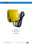
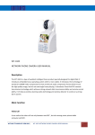
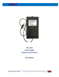
VERSION: 1.2
UPDATED: Nov 2013 WT‐9005 GSM Cell Phone Remote Control Power Switch USER MANUAL INTRODUCTION The New Cell Phone Power Switch is a Quad Band system with its own On Board Power supply and Battery Back‐Up. This system has been developed to minimize the need for over complicated programming. The unit, if already supplied with a SIM Card, can be just plugged in to a Power Socket and the Device to be controlled is also plugged in. One Call to the SIM Card Number will switch the device on permanently. Another Call to the SIM Card will switch the device off permanently. The system can send S.M.S Status reports if required and there are additional programming options available to suit the applications if further security is required and additional functions. WITURA CORPORATION SDN BHD | WT‐9005 GSM Cell Phone Remote Control Power Switch User Manual 1
ADDITIONAL PROGRAMMING FUNCTIONS Getting Started When first booting up the system you will see two separate Coloured LED Lights on the side of the Enclosure and both should light up when the Power Is applied to the unit. The Red LED is to indicate that the Power is applied to the unit. The Green LED is the network Indicator and this light will, when attempting to Log on to the network flash inconsistently until it locates the network. This Green LED will. When logged on to the Network Flash every 4 Seconds Constantly and this indicates the Unit is On Line. A Phone Call to the SIM Card Number will now Latch the Relay permanently ON and Switch the device being Controlled On. The Status of the Relay will remain as on, until the unit receives a second Call to the Unit of which will now Latch the Relay Permanently off. Both Calls used to Latch the Relay either on or off are automatically disconnected, once the relays are activated and never incur any Network Call Costs. This is considered as an Open Mode Function as Factory Default to establish the basic functions for most applications. SMS REPORTING FUNCTIONS WHEN RELAY ACTIVATED AND DEACTIVATED In some applications the customer may require the Confirmation that the Device is actually on and also off, this can be done by activating the command that will send the SMS text alerts back to the Number that has called the Unit to activate the Device. The following SMS Message is sent to the unit to activate this function *PSSW12345*RLYM=ON and you will receive the following SMS Message from the Unit. *RLYM=0N and anyone that calls the unit to latch the relays on and off will receive a SMS Message as *RLY=ON & RLY=OFF The following SMS Message is sent to the unit to deactivate this function *RLYM=0FF and the SMS Relay Status reporting Function is now disabled WITURA CORPORATION SDN BHD | WT‐9005 GSM Cell Phone Remote Control Power Switch User Manual 2
MASTER ADMINISTRATOR NUMBER The system can also be security locked with only one Administrator allowed to change or alter the parameters or settings of the system and this is done using the following SMS Command. This command would always be sent in to program in the number as 8612345678 you would send the following SMS Command to the unit. *PSSW12345*ADM1=8612345678 and you will receive the following SMS Message from the unit. *ADM1=8612345678 and that is now the only telephone that can change the settings and parameters of the system. This is also the only telephone Number that can replace the main administrator Number. POWER DOWN ALARM The system is also pre‐programmed to send S.M.S Text Alerts to the “Master Administrator” in the event that the Power Fails at the site and will also report when the Power is restored with a 60 second delay to prevent sending alerts for short Intermittent power interruptions. If the Power fails at the site the Administrator will receive the following S.M.S text alert. POWER DOWN indicating AC Power Supply has failed When the Power is restored at the site the Administrator will receive the following S.M.S text alert. POWER RESTORED indicating the AC Power Supply has been restored. AUTHORISED USER LIST Once the Master Administrator has been programmed into the system, the authorized User Numbers can be programmed into the system by the Master Administrator using the following commands To Program the Authorized users you would use the *PSSW12345*CLD01= through to the *PSSW12345*CLD05= WITURA CORPORATION SDN BHD | WT‐9005 GSM Cell Phone Remote Control Power Switch User Manual 3
To program the user numbers. You would only require entering the last 7 digits of the telephone number therefore telephone number 003538687654321 you need to send the following SMS Message to the unit as *PSSW12345*CLD01=7654321 and you will receive the following SMS Message from the unit. *CLD01=7654321 and the system will recognize the last 7 digits of the number and allow access to the system and the other 24 User Telephone Numbers are programmed in the same format. LOCKING SECURITY MODE Once all the User Numbers have been programmed into the system, the security mode can be activated which then only allows the Administrator and the Authorized Users to have access to the system. This is done by sending the following SMS Command to the unit as: *PSSW12345*SSM=ON and you will receive the following SMS Message from the unit. *SSM=ON and the security mode is now activated. To deactivate the Security Mode you would send the following SMS Command to the unit as: *PSSW12345*SSM=OFF and you will receive the following SMS Message from the unit. *SSM=OFF and the System is now back in open mode and any telephone number can call the unit to activate the system. CHECKING THE SIGNAL STRENGTH It is possible to check the signal Strength at any time by sending the following SMS Message to the unit. *PSSW*SGH? And you will receive a following similar SMS Message from the unit based on a signal range from <1> through to a maximum of <31> SIGNAL STRENGH < 10 > and this would indicate an acceptable signal strength level and any levels under < 6 > may need using an alternative External antenna or Location. WITURA CORPORATION SDN BHD | WT‐9005 GSM Cell Phone Remote Control Power Switch User Manual 4
SMS Commands *PSSW*SGH? *PSSW12345*RLYM=ON *PSSW12345*RLYM=OFF *PSSW12345*ADM1= *PSSW12345*CLD01‐25
*PSSW12345*SSM=ON
*PSSW12345*SSM=OFF
*PSSW12345*RLY? *PSSW12345*NPW=
*PSSW12345*RESET*
Check Signal Strength Turn On Relay Status Alerts Turn off relay Status Alerts Program Master Admin Number Add User Numbers Turn On Security Mode Turn Off Security Mode Check Relay Status via SMS Change 5 digit Password Reset unit to Factory default
WITURA CORPORATION SDN BHD | WT‐9005 GSM Cell Phone Remote Control Power Switch User Manual 5