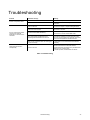
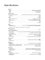
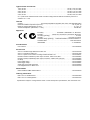
1
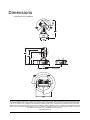
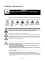
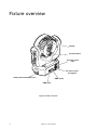
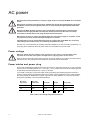
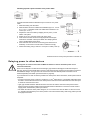
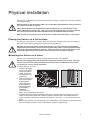
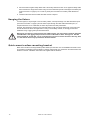
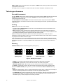
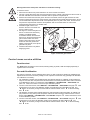
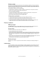
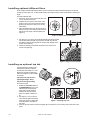
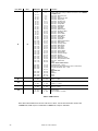
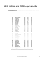
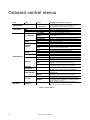
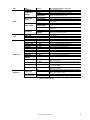
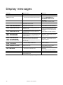
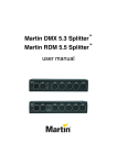
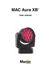
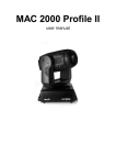
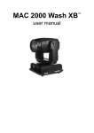
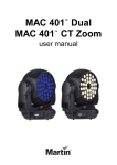
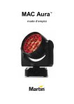
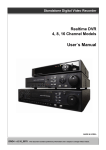
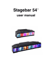
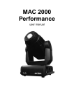
MAC 101
TM
User manual
Dimensions
All dimensions are in millimeters
©2010-2011 Martin Professional A/S. Information subject to change without notice. Martin Professional A/S and all affiliated companies disclaim liability for any injury, damage, direct or indirect loss, consequential or economic loss or any other loss occasioned by
the use of, inability to use or reliance on the information contained in this manual. The Martin logo, the Martin name and all other
trademarks in this document pertaining to services or products by Martin Professional A/S or its affiliates and subsidiaries are trademarks owned or licensed by Martin Professional A/S or its affiliates or subsidiaries. The use of certain patents in MAC 101 products
is licensed by Color Kinetics, Inc. (see details printed on product).
P/N 35000246, Rev. E
Safety Information
WARNING!
Read the safety precautions in this section before
installing, powering, operating or servicing this
product.
The following symbols are used to identify important safety information on the product and in this manual:
DANGER!
Safety hazard.
Risk of severe
injury or death.
DANGER!
Hazardous
voltage. Risk of
lethal or severe
electric shock.
WARNING!
Fire hazard.
WARNING!
LED light
emission. Risk of
eye injury.
WARNING!
WARNING!
Burn hazard. Hot Wear protective
surface. Do not
eyewear.
touch.
WARNING! Refer
to user manual.
Warning! Risk Group 3 (high risk) LED product according to EN 62471. Do not look into the beam at
a distance of less than 8.3 meters (27 ft. 3 inches) from the front surface of the product. Do not view
the light output with optical instruments or any device that may concentrate the beam.
This product is for professional use only. It is not for household use.
This product presents risks of severe injury or death due to fire and burn hazards, electric shock and falls.
Read this manual before installing, powering or servicing the fixture, follow the safety precautions listed
below and observe all warnings in this manual and printed on the fixture. If you have questions about how to
operate the fixture safely, please contact your Martin supplier or call the Martin 24-hour service hotline on
+45 8740 0000, or in the USA on 1-888-tech-180.
PROTECTION FROM ELECTRIC SHOCK
• Disconnect the fixture from AC power before removing or installing any cover or part and when not in use.
• Always ground (earth) the fixture electrically.
• Use only a source of AC power that complies with local building and electrical codes and has both
overload and ground-fault (earth-fault) protection.
• Before using the fixture, check that all power distribution equipment and cables are in perfect condition
and rated for the current requirements of all connected devices.
• Power input and throughput cables must be 3-conductor, rated 20 A minimum, 1.5 mm² (16 AWG)
minimum conductor size, extra hard usage type (ST or equivalent). The cable must be heat-resistant to
90° C (194° F) minimum.
• Use only Neutrik PowerCon NAC3FCA cable connectors to connect to power input sockets. Use only
Neutrik PowerCon NAC3FCB cable connectors to connect to power throughput sockets.
• Isolate the fixture from power immediately if the power plug or any seal, cover, cable, or other component
is damaged, defective, deformed, wet or showing signs of overheating. Do not reapply power until repairs
have been completed.
Safety Information
3
• Do not expose the fixture to rain or moisture.
• Refer any service operation not described in this manual to a qualified technician.
• Socket outlets used to supply MAC 101 fixtures with power or external power switches must be located
near the fixtures and easily accessible so that the fixtures can easily be disconnected from power.
PROTECTION FROM BURNS AND FIRE
• Do not operate the fixture if the ambient temperature (Ta) exceeds 40° C (104° F).
• The exterior of the fixture becomes hot during use. Avoid contact by persons and materials. Allow the
fixture to cool for at least 10 minutes before handling.
• Keep all combustible materials (e.g. fabric, wood, paper) at least 100 mm (3.9 in.) away from the head.
• Keep flammable materials well away from the fixture.
• Ensure that there is free and unobstructed airflow around the fixture.
• Do not illuminate surfaces within 200 mm (7.9 ins.) of the MAC 101.
• Do not attempt to bypass thermostatic switches or fuses.
• If you relay power from one fixture to another using power throughput sockets, do not connect more than
ten MAC 101 fixtures in total to each other in an interconnected chain.
• Connect only other MAC 101 fixtures to MAC 101 power throughput sockets. Do not connect any other
type of device to these sockets.
• Do not stick filters, masks or other materials onto any optical component.
• Do not modify the fixture in any way not described in this manual
• Install only genuine Martin parts.
PROTECTION FROM INJURY
• Do not look continuously at LEDs from a distance of less than 8.3 meters (27 ft. 3 inches) from the front
surface of the fixture without protective eyewear such as shade 4-5 welding goggles. At less than this
distance, the LED emission can cause eye injury or irritation. At distances of 8.3 meters (27 ft. 3 inches)
and above, light output is harmless to the naked eye provided that the eye’s natural aversion response is
not overcome.
• Do not look at LEDs with magnifiers, telescopes, binoculars or similar optical instruments that may
concentrate the light output.
• Ensure that persons are not looking at the LEDs from within 8.3 meters (27 ft. 3 inches) when the product
lights up suddenly. This can happen when power is applied, when the product receives a DMX signal, or
when SERVICE menu items are selected.
• If suspending from a rigging structure, fasten the fixture to a rigging clamp with an M12 bolt screwed into
the threaded hole in the center of the base of the fixture. The bolt must protrude at least 20 - 30 mm
(0.8 - 1.2 ins.) into the fixture. If the fixture is suspended by any other method, an M12 bolt must be
tightened into this hole so that it protrudes at least 20 - 30 mm (0.8 - 1.2 ins.) into the fixture.
• Install as described in this manual a secondary attachment such as a safety cable that is approved by an
official body such as TÜV as a safety attachment for the weight of all the fixtures it secures. The safety
cable must comply with EN 60598-2-17 Section 17.6.6 and be capable of bearing a static suspended load
ten times the weight of the fixture.
• Ensure that any supporting structure and/or hardware used can hold at least 10 times the weight of all the
devices they support.
• Allow enough clearance around the head to ensure that it cannot collide with an object or another fixture
when it moves.
• Check that all external covers and rigging hardware are securely fastened.
• Block access below the work area and work from a stable platform whenever installing, servicing or
moving the fixture.
• Do not operate the fixture with missing or damaged covers, shields or any optical component.
4
MAC 101 user manual
Contents
Dimensions . . . . . . . . . . . . . . . . . . . . . . . . . . . . . . . . . . . . . . . . . . . . . . . . . . . . . . . . . . . . . . . . . . . . . . . . 2
Safety Information . . . . . . . . . . . . . . . . . . . . . . . . . . . . . . . . . . . . . . . . . . . . . . . . . . . . . . . . . . . . . . . . . . 3
Fixture overview . . . . . . . . . . . . . . . . . . . . . . . . . . . . . . . . . . . . . . . . . . . . . . . . . . . . . . . . . . . . . . . . . . . 6
Introduction . . . . . . . . . . . . . . . . . . . . . . . . . . . . . . . . . . . . . . . . . . . . . . . . . . . . . . . . . . . . . . . . . . . . . . . . 7
Using for the first time . . . . . . . . . . . . . . . . . . . . . . . . . . . . . . . . . . . . . . . . . . . . . . . . . . . . . . . . . . . . . . . 7
AC power . . . . . . . . . . . . . . . . . . . . . . . . . . . . . . . . . . . . . . . . . . . . . . . . . . . . . . . . . . . . . . . . . . . . . . . . . . 8
Power voltage . . . . . . . . . . . . . . . . . . . . . . . . . . . . . . . . . . . . . . . . . . . . . . . . . . . . . . . . . . . . . . . . . . . . . 8
Power cables and power plug . . . . . . . . . . . . . . . . . . . . . . . . . . . . . . . . . . . . . . . . . . . . . . . . . . . . . . . . . 8
Relaying power to other devices . . . . . . . . . . . . . . . . . . . . . . . . . . . . . . . . . . . . . . . . . . . . . . . . . . . . . . . 9
Data link . . . . . . . . . . . . . . . . . . . . . . . . . . . . . . . . . . . . . . . . . . . . . . . . . . . . . . . . . . . . . . . . . . . . . . . . . . 10
Tips for reliable data transmission . . . . . . . . . . . . . . . . . . . . . . . . . . . . . . . . . . . . . . . . . . . . . . . . . . . . . 10
Connecting the data link . . . . . . . . . . . . . . . . . . . . . . . . . . . . . . . . . . . . . . . . . . . . . . . . . . . . . . . . . . . . 10
Physical installation . . . . . . . . . . . . . . . . . . . . . . . . . . . . . . . . . . . . . . . . . . . . . . . . . . . . . . . . . . . . . . . 11
Placing the fixture on a flat surface . . . . . . . . . . . . . . . . . . . . . . . . . . . . . . . . . . . . . . . . . . . . . . . . . . . .
Mounting the fixture on a truss . . . . . . . . . . . . . . . . . . . . . . . . . . . . . . . . . . . . . . . . . . . . . . . . . . . . . . .
Hanging the fixture. . . . . . . . . . . . . . . . . . . . . . . . . . . . . . . . . . . . . . . . . . . . . . . . . . . . . . . . . . . . . . . . .
Quick-mount surface mounting bracket . . . . . . . . . . . . . . . . . . . . . . . . . . . . . . . . . . . . . . . . . . . . . . . . .
11
11
12
12
Setup . . . . . . . . . . . . . . . . . . . . . . . . . . . . . . . . . . . . . . . . . . . . . . . . . . . . . . . . . . . . . . . . . . . . . . . . . . . . . 13
Control panel and menu navigation . . . . . . . . . . . . . . . . . . . . . . . . . . . . . . . . . . . . . . . . . . . . . . . . . . . .
DMX address setting . . . . . . . . . . . . . . . . . . . . . . . . . . . . . . . . . . . . . . . . . . . . . . . . . . . . . . . . . . . . . . .
DMX modes . . . . . . . . . . . . . . . . . . . . . . . . . . . . . . . . . . . . . . . . . . . . . . . . . . . . . . . . . . . . . . . . . . . . . .
Tailoring performance . . . . . . . . . . . . . . . . . . . . . . . . . . . . . . . . . . . . . . . . . . . . . . . . . . . . . . . . . . . . . .
Restoring factory default settings . . . . . . . . . . . . . . . . . . . . . . . . . . . . . . . . . . . . . . . . . . . . . . . . . . . . .
13
13
13
14
15
Operation and effects . . . . . . . . . . . . . . . . . . . . . . . . . . . . . . . . . . . . . . . . . . . . . . . . . . . . . . . . . . . . . 16
Service and maintenance . . . . . . . . . . . . . . . . . . . . . . . . . . . . . . . . . . . . . . . . . . . . . . . . . . . . . . . . . . 17
Cleaning. . . . . . . . . . . . . . . . . . . . . . . . . . . . . . . . . . . . . . . . . . . . . . . . . . . . . . . . . . . . . . . . . . . . . . . . .
Control menu service utilities. . . . . . . . . . . . . . . . . . . . . . . . . . . . . . . . . . . . . . . . . . . . . . . . . . . . . . . . .
Fixture readouts. . . . . . . . . . . . . . . . . . . . . . . . . . . . . . . . . . . . . . . . . . . . . . . . . . . . . . . . . . . . . . . . . . .
Lubrication . . . . . . . . . . . . . . . . . . . . . . . . . . . . . . . . . . . . . . . . . . . . . . . . . . . . . . . . . . . . . . . . . . . . . . .
Installing optional diffuser filters. . . . . . . . . . . . . . . . . . . . . . . . . . . . . . . . . . . . . . . . . . . . . . . . . . . . . . .
Installing an optional top hat . . . . . . . . . . . . . . . . . . . . . . . . . . . . . . . . . . . . . . . . . . . . . . . . . . . . . . . . .
17
18
19
19
20
20
DMX protocol . . . . . . . . . . . . . . . . . . . . . . . . . . . . . . . . . . . . . . . . . . . . . . . . . . . . . . . . . . . . . . . . . . . . . 21
LEE colors and RGB equivalents . . . . . . . . . . . . . . . . . . . . . . . . . . . . . . . . . . . . . . . . . . . . . . . . . . 23
Onboard control menus. . . . . . . . . . . . . . . . . . . . . . . . . . . . . . . . . . . . . . . . . . . . . . . . . . . . . . . . . . . . 24
Display messages . . . . . . . . . . . . . . . . . . . . . . . . . . . . . . . . . . . . . . . . . . . . . . . . . . . . . . . . . . . . . . . . . 26
Troubleshooting . . . . . . . . . . . . . . . . . . . . . . . . . . . . . . . . . . . . . . . . . . . . . . . . . . . . . . . . . . . . . . . . . . 27
Specifications . . . . . . . . . . . . . . . . . . . . . . . . . . . . . . . . . . . . . . . . . . . . . . . . . . . . . . . . . . . . . . . . . . . . . 28
Fixture overview
Display
Control buttons
AC mains power
input
AC mains power
throughput
Safety cable attachment point
DMX output
DMX input
Figure 1: Fixture overview
6
MAC 101 user manual
Introduction
Thank you for selecting the MAC 101™, an intelligent lighting fixture from Martin Professional™. This
compact LED-based moving-head washlight features:
• Cree XP-E high-power RGB emitters
• DMX control
• Onboard control panel and backlit LCD graphic display
• RGB color mixing with color temperature control
• ‘Color wheel’ color-snap feature
• Smooth electronic dimming
• Electronic shutter with strobe and pulse effects
• 540° pan and 240° tilt ranges
• Three DMX control modes:
- Raw RGB + CTC
- Calibrated RGB + CTC
- Basic (color-wheel only, RGB + CTC disabled)
For the latest firmware updates, documentation, and other information about this and all Martin Professional
products, please visit the Martin website at http://www.martin.com
Comments or suggestions regarding this document may be e-mailed to [email protected] or posted to:
Technical Documentation, Martin Professional A/S, Olof Palmes Allé 18, DK-8200 Aarhus N, Denmark.
Using for the first time
Warning! Read “Safety Information” on page 3 before installing, powering, operating or servicing
the MAC 101. Before applying power to the fixture:
• Check the Martin Professional website at www.martin.com for the most recent user documentation and
technical information about the MAC 101. Martin user manual revisions are identified by the revision letter
at the bottom of page 2.
• Carefully review “Safety Information” on page 3.
• Check that the local AC mains power source falls within the fixture’s power voltage and frequency ranges.
• See “Power cables and power plug” on page 8. Install a Neutrik PowerCon NAC3FCA power input
connector on a suitable power cable. If drawing power from a mains power outlet, install a suitable power
plug on the power cable.
Introduction
7
AC power
Warning! Read “Safety Information” starting on page 3 before connecting the MAC 101 to AC mains
power.
Warning! For protection from electric shock, the MAC 101 must be grounded (earthed). The power
distribution circuit must be equipped with a fuse or circuit breaker and ground-fault (earth-fault)
protection.
Warning! The MAC 101 does not have a power on/off switch. Socket outlets or external power
switches used to supply the MAC 101 with power must be located near the fixture and easily
accessible so that the fixtures can easily be disconnected from power.
Warning! Do not insert or remove live Neutrik PowerCon connectors to apply or cut power, as this
may cause arcing at the terminals that will damage the connectors.
Important! Do not use an external dimming system to supply power to the MAC 101, as this may
cause damage to the fixture that is not covered by the product warranty.
The MAC 101 can be hard-wired to a building electrical installation if you want to install it permanently, or a
power plug that is suitable for the local power outlets can be installed on the power cable.
Power voltage
Warning! Check that the voltage range specified on the fixture’s serial number label
matches the local AC mains power voltage before applying power to the fixture.
MAC 101 fixtures accept AC mains power at 100-240 V nominal, 50/60 Hz. Do not apply AC mains power to
the fixture at any other voltage than that specified on the fixture’s serial number label.
Power cables and power plug
Power input and throughput cables must be rated 20 A minimum, have three conductors 1.5 mm² (16 AWG)
minimum and a total cable diameter of 5 - 15 mm (0.2 - 0.6 in.). Cables must be extra hard usage type (ST
or equivalent) and heat-resistant to 90° C (194° F) minimum.
If you install a power plug on the power cable, install a grounding-type (earthed) plug that is rated 20 A
minimum. Follow the plug manufacturer’s instructions. Table 1 shows standard wire color-coding schemes
and some possible pin identification schemes; if pins are not clearly identified, or if you have any doubts
about proper installation, consult a qualified electrician.
Wire Color
(EU models)
Wire Color
(US models)
Conductor
Symbol
Screw (US)
brown
black
live
L
yellow or brass
blue
white
neutral
N
silver
yellow/green
green
ground (earth)
or
Table 1: Wire color-coding and power connections
8
MAC 101 user manual
green
Installing a power input connector on a power cable
Housing
Insert
Chuck
To install a Neutrik PowerCon NAC3FCA input connector on a power
cable:
1. Slide the bushing over the cable.
2. Slide the white chuck over cables with a diameter (Da) of 5 - 10 mm
(0.2 - 0.4 in.), or the black chuck over cables with a diameter of 10 15 mm (0.4 - 0.6 in.).
3. Prepare the end of the cable by stripping 20 mm (0.8 in.) of the
cable’s outer jacket.
4. Strip 8 mm (1/3 in.) from the end of each of the wires.
5. Insert each of the wire ends into the appropriate terminal (see
instructions and Table 1 above) and fasten the clamping device
using a small flathead screw driver.
6. Push and insert the chuck into the housing (note that there is a
raised key on the chuck to ensure that it is oriented correctly).
7. Fasten the bushing using a wrench to a torque of 2.5 Nm (1.8 lb.-ft).
Bushing
Cable end
Terminals
Illustrations above used by kind permission of Neutrik AG
Relaying power to other devices
Warning! Do not connect more than ten MAC 101 fixtures in total to AC mains power in one
interconnected chain.
Power can be relayed to another device via the light-grey PowerCon throughput socket that accepts a
light-grey PowerCon NAC3FCB cable connector. Note that blue input and light-grey throughput connectors
have different designs: one type cannot be connected to the other. Neutrik power connectors can be
ordered separately from Martin (see Accessories on page 29).
If you link fixtures in a chain so that they all draw AC mains power via the first fixture, certain points must be
respected:
• An extra hard usage, three-conductor, 16 AWG or 1.5 mm2 cable with ST or equivalent cable jacket must
be used to connect the first fixture to AC mains power and to interconnect all the fixtures in the chain up to
a maximum of ten fixtures in total.
• Light-grey Neutrik PowerCon NAC3FCB connectors must be used to draw AC mains power from the
fixtures’ power throughput sockets and blue Neutrik PowerCon NAC3FCA connectors must be used to
supply power at the fixture’s power input sockets.
• No matter what the AC mains power voltage is, do not connect more than ten MAC 101 fixtures in total
(i.e. including the first fixture) to AC mains power in one interconnected daisy chain using power input and
throughput connectors.
AC power
9
Data link
A DMX 512 data link is required in order to control a MAC 101 via DMX.
The MAC 101 has 5-pin XLR connectors for DMX data input and output. The pin-out on all connectors is pin
1 = shield, pin 2 = cold (-), and pin 3 = hot (+). Pins 4 and 5 in the 5-pin XLR connectors are not used in the
MAC 101 but are available for possible additional data signals as required by the DMX512-A standard.
Standard pin-out is pin 4 = data 2 cold (-) and pin 5 = data 2 hot (+).
The MAC 101 is not subject to the limit of 32 devices per daisy-chained link which is common in Martin
fixtures. Instead, the number of fixtures is limited to either 256 or the number of DMX channels required by
the fixtures in relation to the 512 channels available in one DMX universe, whichever is lower. This means
that:
• In 8-channel Basic DMX mode, up to 64 MAC 101 fixtures (or groups of fixtures with identical control) may
be independently controlled on one link, up to a maximum of 256 fixtures.
• In 12-channel Extended DMX mode, up to 42 MAC 101 fixtures (or groups of fixtures with identical
control) may be independently controlled on one link up to a maximum of 256 fixtures.
To add more fixtures or groups of fixtures with independent control, add a DMX universe and another
daisy-chained link.
Tips for reliable data transmission
• Use shielded twisted-pair cable designed for RS-485 devices: standard microphone cable cannot transmit
control data reliably over long runs. 24 AWG cable is suitable for runs up to 300 meters (1000 ft). Heavier
gauge cable and/or an amplifier is recommended for longer runs.
• Never use both a fixture’s outputs to split a DMX link. To split the link into branches, use a splitter such as
the Martin 4-Channel Opto-Isolated RS-485 Splitter/Amplifier.
• Terminate the link by installing a termination plug in the output socket of the last fixture. The termination
plug, which is a male XLR plug with a 120 Ohm, 0.25 Watt resistor soldered between pins 2 and 3, “soaks
up” the control signal so it does not reflect and cause interference. If a splitter is used, terminate each
branch of the link.
Connecting the data link
To connect the MAC 101 to data:
1. Connect the DMX data output from the controller to the closest MAC 101’s male 5-pin XLR DMX input
connector.
2. Connect the DMX output of the fixture closest to the controller to the DMX input of the next fixture and
continue connecting fixtures output to input.
3. Terminate the last fixture on the link with a 120 Ohm resistor.
10
MAC 101 user manual
Physical installation
The MAC 101 can be placed on a horizontal surface such as a stage or clamped to a truss in any orientation
using a rigging clamp.
Warning! Attach an approved safety cable to one of the safety cable attachment points on the base
(see “Fixture overview” on page 6).
Check that all surfaces to be illuminated are minimum 200 mm (7.9 ins.) from the fixture, that
combustible materials (wood, fabric, paper, etc.) are minimum 100 mm (3.9 in.) from the head, that
there is free airflow around the fixture and that there are no flammable materials nearby.
Make sure that it is impossible for the moving head to collide with another fixture or other object.
Placing the fixture on a flat surface
The MAC 101 can be placed on a stage or other level, flat surface. Check that the surface can support at
least 10 times the weight of all fixtures and equipment to be installed on it.
Warning! The supporting surface must be hard and flat or air vents in the base may be blocked,
which will cause overheating. Secure the fixture against falling. Attach a securely anchored safety
cable to the safety cable attachment point (see “Fixture overview” on page 6) if the fixture is to be
placed above ground level in any location where it may fall and cause injury or damage.
Mounting the fixture on a truss
The MAC 101 can be clamped to a truss or similar rigging structure in any orientation.
Warning! Use a rigging clamp with an M12 bolt if suspending the fixture from its base. The clamp
must be screwed into the central threaded hole in the fixture base. The M12 bolt must protrude
20 - 30 mm (0.8 - 1.2 ins.) into the fixture base.
In
s
ta
l
M
12
b W
Se olt a
e wh rni
U en ng
se
r M su !
s
an pe
ua nd
l! ing
fix
tu
re
.
To clamp a MAC 101 to a truss:
1. Check that the rigging
structure can support
at least 10 times the
weight of all fixtures
and equipment to be
installed on it.
2. Obtain a rigging clamp
such as the G-clamp
(P/N 91602003),
Half-coupler clamp
(P/N 91602005) or
Quick trigger clamp
(P/N 91602007)
Figure 2: Rigging clamp bolt
available as
accessories from
Martin. An omega bracket is not required.
3. Check that the rigging clamp is undamaged and can bear at least 10 times the weight of the fixture.
Fasten the clamp to the fixture with a minimum grade 8.8 steel M12 bolt in the threaded hole in the
center of the base of the fixture. The bolt must protrude 20 - 30 mm (0.8 - 1.2 ins.) into the base of the
fixture.
4. Block access under the work area. Working from a stable platform, hang the fixture on the truss with the
arrow on the base towards the area to be illuminated. Tighten the rigging clamp.
Physical installation
11
5. Secure the fixture against clamp failure with a secondary attachment such as an approved safety cable
that is rated for the weight of the fixture using one of the attachment points at the edges of the base (see
“Fixture overview” on page 6). Do not use any other part of the fixture as a safety cable attachment
point.
6. Check that the head will not collide with other fixtures or objects.
Hanging the fixture
In some regions, it may be legal to use two safety cables, one looped through one cable attachment point
(see “Fixture overview” on page 6) and the other looped through the other cable attachment point, to
suspend the fixture. If one cable fails, the other will provide secondary attachment.
However, this suspension method is not recommended as it will not hold the base firmly, and moving pan
and tilt will cause the fixture and light beam to swing uncontrollably. Instead, we strongly recommend
installation using a rigging clamp as described above.
Warning! If you choose to suspend using two cables anyway, you must install a minimum 8.8 grade
steel M12 bolt in the rigging clamp hole in the center of the fixture’s base. See Figure 2. The bolt
must protrude 20 - 30 mm (0.8 - 1.2 ins.) into the base. If you do not secure the base in this way, there
is a risk that the fixture may separate from the base and fall.
Quick-mount surface mounting bracket
Quick-mount surface mounting brackets (P/N 91606017) for the MAC 101 are available from Martin in sets
of 5 brackets. The bracket can be screwed to a surface and the MAC 101 mounted on and removed from the
bracket in seconds. Installation instructions are supplied with the brackets.
12
MAC 101 user manual
Setup
Warning! Read “Safety Information” on page 3 before installing, powering, operating or servicing
the MAC 101.
Control panel and menu navigation
The onboard control panel and backlit graphic display are used to set the MAC 101’s DMX address,
configure individual fixture settings (personality), read out data and execute service utilities. See “LEE
colors and RGB equivalents” on page 23 for a complete list of menus and commands.
Using the control buttons
(Enter).
(Up) and (Down) to scroll within a menu or adjust values.
• To enter a menu, select a function or apply a selection, press
• Press
• To escape a function or move back one level in the menu structure, press
(Menu / Escape).
Control button reset shortcut
• Holding
(Menu/Escape) pressed in and pressing (Up) forces the fixture to reset.
Display panel functions
The DMX address is shown in the display panel when the MAC 101 is powered on and has reset.
The display panel backlighting indicates fixture status as follows:
• The display dims to zero during resets.
• The display flashes slowly if the fixture is not receiving a valid DMX signal unless the control buttons are
used. In this case, the display behaves normally until the buttons have not been used for a short period,
then begins to flash slowly again.
• The display can be set to go into sleep mode via PERSONALITY → DISPLAY in the control menu.
Connecting a DMX signal ‘wakes up’ the display.
DMX address setting
The DMX address, also known as the start channel, is the first channel used to receive instructions from the
controller. For independent control, each fixture must be assigned its own control channels. Two MAC 101
fixtures may share the same address, however, if identical behavior is desired. Address sharing can be
useful for diagnostic purposes and symmetric control, particularly when combined with the inverse pan and
tilt options.
The DMX address is configured using the DMX ADDRESS menu in the control panel.
DMX modes
DMX control mode is selected in the CONT MODE (control mode) menu. The MAC 101 provides three DMX
control modes:
• RAW is an uncalibrated RGB mode that gives maximum output and slightly more saturated color, but
there may be inconsistency in color balance between fixtures. It uses 12 DMX channels.
• RGB is a calibrated RGB mode that gives slightly less output than RAW mode but consistent color
balance across fixtures. It uses 12 DMX channels.
• BASIC is a basic mode that only uses 8 DMX channels but only gives access to the color wheel effect for
color control – RGB and CTC are not available.
Setup
13
RAW and RGB modes include the same control options as BASIC mode, but they provide 4 extra channels
to give RGB control and CTC.
See “DMX protocol” on page 21 for details of the DMX commands available in the different modes.
Tailoring performance
Pan and tilt movement
The P/T SPEED settings set the maximum speed of pan and tilt movement. FAST optimizes for speed and
SLOW optimizes for smoothness of movement. NORMAL is the default setting and gives a good
compromise between these two.
The PAN INVERT and TILT INVERT commands reverse the direction of pan and tilt, and the SWAP
command sends pan commands to tilt and vice versa. These settings are useful for symmetrical effects with
multiple fixtures.
Cooling
FANS gives you a choice of two settings:
• The default setting REGULATED should suit use in all normal situations and ensure excellent service
lifetimes for all components.
• FULL maximizes cooling and reduces the operating temperature of the components in the head. It is
recommended when the MAC 101 is used intensively in a warm environment or in fixed installations. Note
that it will give increased fan noise compared to the other cooling modes.
Whatever cooling mode is selected, a thermal cutout shuts down power to the LEDs if the fixture
temperature exceeds safe limits. If this occurs, you must reset the fixture via the control menus or via DMX,
or cycle power to the fixture off and on again.
If a thermal shutdown occurs, you are pushing the fixture to its limits. Clean the fixture, particularly the air
vents, and check that there is sufficient airflow around the fixture. Consider increasing ventilation, reducing
the ambient temperature, or switching to FULL mode. Contact Martin for service if a thermal shutdown
persists.
Dimming
DMX %
Optically linear
DMX %
Square law
Output
Output
Output
Output
DIMMER CURVE provides four dimming options (see Figure 3):
DMX %
Inverse square law
DMX %
S-curve
Figure 3: Dimming curve options
• LINEAR – the increase in light intensity appears to be linear as DMX value is increased.
• SQUARE LAW – light intensity control is finer at low levels and coarser at high levels.
• INVERSE SQUARE LAW – light intensity control is coarser at low levels and finer at high levels.
• S-CURVE – light intensity control is finer at low levels and high levels and coarser at medium levels.
Whichever DIMMER CURVE option you select, you can choose between FAST or SMOOTH dimming
settings:
• FAST is the default setting. It gives a virtually instantaneous reaction when you dim from one intensity to
another, but dimming slowly from one intensity to another may appear slightly uneven.
• The SMOOTH setting gives smoother dimming during slow changes in intensity, but it limits the speed of
dimming changes slightly. This makes it ideal for slow, smooth dimming, but a short time-lag may be
noticeable if you try to dim quickly from one intensity to another.
14
MAC 101 user manual
Restoring factory default settings
The MAC 101 factory default settings can be restored by applying a FACTORY DEFAULT → LOAD
command.
Setup
15
Operation and effects
Warning! Read “Safety Information” on page 3 before installing, powering, operating or servicing
the MAC 101.
This section describes only DMX control features that require particular explanation. See “DMX protocol” on
page 21 for a full list of the DMX channels and values required to control the different effects.
Pan and tilt
The MAC 101’s moving head can be panned through 540° and tilted through 240°. The speed of pan/tilt
movement can be adjusted via the control panel.
All DMX modes offer fine control of pan and tilt. In each case, the main control channel sets the first 8 bits
(the most significant byte or MSB), and the fine channel sets the second 8 bits (the least significant byte or
LSB) of the 16-bit control byte. In other words, the fine channel works within the position set by the main
channel.
Shutter effect
The electronic ‘shutter’ effect provides instant open and blackout, variable speed regular and random strobe
and opening/closing pulse effects as well as burst and sinewave effects.
Dimming
Overall intensity can be adjusted 0 - 100% using electronic dimming. See “Dimming” on page 14.
Controlling color
Color wheel effect
The electronic ‘color wheel’ effect gives the convenience and feel of a mechanical color wheel and lets you
snap between 33 different full LEE-referenced colors. You can also scroll continuously forwards or
backwards through the colors or display random colors at variable speed.
The color wheel effect is available in all DMX modes.
The approximate RGB equivalents of the ‘color wheel’ colors are given in “LEE colors and RGB equivalents”
on page 23.
Color wheel priority
Even if the fixture is set to RAW or RGB mode, the color wheel effect channel still has priority over the RGB
channels. To use the RGB channels, you must set the color wheel effect channel to a DMX value from 000 009. If you move the color wheel channel to a DMX value above 009 at any point, the color wheel effect
takes over and overrides RGB control.
RGB color mixing
RGB color mixing is available in raw or calibrated modes:
• Raw RGB mode (RAW) is uncalibrated and allows all LEDs to be operated to their absolute maximum
output regardless of color calibration issues.
• Calibrated RGB mode (RGB) gives slightly reduced LED power but sets LEDs to their factory calibration
output power to give the best-matched color and white output across multiple fixtures.
CTC (Color Temperature Control)
If the fixture is set to RAW or RGB mode, setting the CTC channel (12) to a DMX value greater than 019 will
adjust the fixture’s overall color temperature, i.e. the color that has been set using the color wheel channel
or the RGB channels. Note that the more saturated the color, the less it will be affected by adjustments in
color temperature. The biggest CTC variation is available when displaying white.
Overall color temperature can be varied from 10 000 - 2 500 K. The default color temperature is 5 600 K.
16
MAC 101 user manual
Service and maintenance
Warning! Read “Safety Information” on page 3 before servicing the MAC 101.
Warning! Disconnect the fixture from AC mains power and allow to cool for at least 10
minutes before handling. Do not view the light output from less than 8.3 meters (27 ft. 3
inches) without shade 4-5 welding goggles. Be prepared for the fixture to light suddenly if
connected to power.
Warning! Refer any service operation not described in this user manual to a qualified
service technician.
Important! Excessive dust, smoke fluid, and particle buildup degrades performance, causes
overheating and will damage the fixture. Damage caused by inadequate cleaning or maintenance is
not covered by the product warranty.
The user will need to clean the MAC 101 periodically, and it is also possible for the user to update the
firmware and install the optional diffuser accessory available from Martin. All other service operations on the
MAC 101 must be carried out by Martin Professional or its approved service agents.
Installation, on-site service and maintenance can be provided worldwide by the Martin Professional Global
Service organization and its approved agents, giving owners access to Martin’s expertise and product
knowledge in a partnership that will ensure the highest level of performance throughout the product’s
lifetime. Please contact your Martin supplier for details.
It is Martin policy to apply the strictest possible calibration procedures and use the best quality materials
available to ensure optimum performance and the longest possible component lifetimes. However, LEDs are
subject to wear and tear over the life of the product, resulting in gradual changes in color and overall
brightness over many thousands of hours of use. The extent of wear and tear depends heavily on operating
conditions and environment, so it is impossible to specify precisely whether and to what extent LED
performance will be affected. However, you may eventually need to ask Martin Professional to replace LEDs
if their characteristics are affected by wear and tear after an extended period of use and if you require
fixtures to perform within very precise optical and color parameters.
The manufacturer’s LED lifetime data is based on performance under the manufacturer’s test conditions. As
with all LEDs, the gradual reduction in luminous output will be accelerated when LEDs are used in a fixture,
where conditions are much tougher than in manufacturer’s testing. To maximize LED lifetimes, keep the
ambient temperature as low as possible and drive the LEDs no harder and for no longer than necessary.
Cleaning
Cleaning schedules for lighting fixtures vary greatly depending on the operating environment. It is therefore
impossible to specify precise cleaning intervals for the MAC 101. Environmental factors that may result in a
need for frequent cleaning include:
• Use of smoke or fog machines.
• High airflow rates (near air conditioning vents, for example).
• Presence of cigarette smoke.
• Airborne dust (from stage effects, building structures and fittings or the natural environment at outdoor
events, for example).
If one or more of these factors is present, inspect fixtures within their first 100 hours of operation to see
whether cleaning is necessary. Check again at frequent intervals. This procedure will allow you to assess
cleaning requirements in your particular situation. If in doubt, consult your Martin dealer about a suitable
maintenance schedule.
Use gentle pressure only when cleaning, and work in a clean, well-lit area. Do not use any product that
contains solvents or abrasives, as these can cause surface damage.
Service and maintenance
17
Warning! Disconnect from power and allow to cool before cleaning.
To clean the fixture:
1. Disconnect the fixture from power and allow it to cool for at least 10 minutes.
2. Vacuum or gently blow away dust and loose particles from the outside of the fixture and the air vents at
the back and sides of the head and in the base with low-pressure compressed air.
3. Remove the central screw from the grill on the front of the head, remove the grill and clean the LED
lenses by wiping gently with a soft, clean lint-free cloth moistened with a weak detergent solution. Do not
rub the surface hard: lift particles off with a soft repeated press. Dry with a soft, clean, lint-free cloth or
low-pressure compressed air. Remove stuck particles with an unscented tissue or cotton swab
moistened with glass cleaner or distilled water.
4. Reinstall the grill over the LED
lenses in the front of the head and
secure it with its screw.
5. See Figure 4. Remove the grill from
the fan on the back of the head by
inserting a small flat-bladed
screwdriver between the head and
the arrow on the grill and levering the
grill out of the head. Use cotton
swabs (cotton buds) and a vacuum
cleaner to clean the grill and the
blades of the head fan, then clip the
grill back into place.
6. Check that the fixture is dry before
reapplying power.
Figure 4: Head fan grill removal
Control menu service utilities
Functions test
The TEST feature provides four test routines, allowing testing of pan/tilt, LEDs and display separately or
together without a controller.
Pan and tilt calibration
Pan and tilt on the MAC 101 are calibrated at the factory so that movement is identical in multiple fixtures.
Adjustment should not be necessary initially, but over a period of use fixtures may gradually lose calibration.
If re-calibration is necessary:
1. Pan calibration is easiest when multiple fixtures are stacked vertically. To calibrate, set tilt positions for
easy one-over-the-other comparison and set each fixture to the same pan DMX value. Select one fixture
to be the reference fixture. On that fixture, select SERVICE → CALIBRATION → PAN OFFSET and
press
. Wait for the fixture to move to its pan calibration position.
. Wait
2. On each of the other fixtures, select SERVICE → CALIBRATION → PAN OFFSET and press
for the head to move to the pan calibration position, then adjust the pan offset using the
and
buttons as necessary to align the beam with the reference beam. Press
to save the setting,
then
to exit.
3. Tilt calibration is easiest when multiple fixtures are arranged side-by-side horizontally. To calibrate, set
pan positions for easy side-by-side comparison. Select one fixture to be the reference fixture. On that
. Wait for the fixture to move
fixture, select SERVICE → CALIBRATION → TILT OFFSET and press
to its tilt calibration position.
. Wait
4. On each of the other fixtures, select SERVICE → CALIBRATION → TILT OFFSET and press
and
for the head to move to the tilt calibration position, then adjust the tilt offset using the
buttons as necessary to align the beam with the reference beam. Press
to save the setting,
to exit.
then
18
MAC 101 user manual
Software upload
The MAC 101 is loaded with both software (that can be installed and updated by the user) and firmware
(that is internal and accessible to Martin Service and its authorized partners only). Software updates are
available from the Martin website and can be installed with a PC and Martin USB Duo DMX Interface box
that can upload software to one fixture at a time.
The following are required in order to install software:
• The latest version of the MAC 101 software, available for download free of charge from the Product
Support area of the Martin website at http://www.martin.com
• A PC running Windows 98/2000/XP
• The Windows-based Martin Uploader application available for download free of charge from the
Downloads Area of the Martin website at http://www.martin.com
• Martin USB Duo DMX Interface Box with its supplied cables.
Installing software: normal method
1.
2.
3.
4.
Connect the Uploader hardware to a MAC 101 fixture's data input connector.
Upload the fixture software as described in the uploader’s help file or user documentation.
Disconnect the Uploader hardware and reconnect the fixture to the DMX link.
Cycle power off and on. Check that the fixture resets correctly. If an error message appears in the
display, cycle power off and on again and check that the fixture now resets correctly.
Fixture readouts
DMX input signal
The DMX LIVE menu lets you view the DMX values received on each channel. If the fixture does not
behave as expected, reading the DMX values can help you troubleshoot the problem.
Fixture status
The MAC 101 gives fixture status readouts in the INFO menu:
• Current software/firmware version information.
• Temperature readouts from the power supply unit in the base and LED PCB in the head. In each case,
you can view the current temperature and the maximum temperature reached since the readout was last
reset. The maximum temperatures can be reset individually. The TOTAL temperature counters are not
resettable.
• Power on hours. You can view the number of hours since the resettable counter was last reset or the total
number of hours since manufacture. You can also reset the resettable counter to zero.
• The manufacturer’s serial number and the fixture’s RDM ID number.
Display messages
If an error occurs, the MAC 101 gives fixture status readouts in the display. See “Display messages” on
page 26.
Lubrication
In general, the MAC 101 does not require lubrication. However, depending on use conditions, the moving
parts in the pan and tilt mechanisms may eventually require reapplication of lubricant. Excessive noise
during pan/tilt movement is a sign that lubrication may be required. This operation can be carried out by a
Martin service partner if necessary.
Service and maintenance
19
Installing optional diffuser filters
A set of eight medium-angle diffuser filters can be ordered from Martin (P/N 91616018) as an optional
accessory for the MAC 101. A diffuser filter softens the output from the LEDs and provides a wider beam
angle.
To install a diffuser filter:
1. Shut down power to the fixture and allow it to
cool for at least 10 minutes.
2. Release the Torx screw in the center of the
spill ring on the front of the head and lift the
spill ring off. Keep the screw for use during
reassembly.
3. Place the diffuser filter over the lens plate so
that the cutouts in the diffuser locate over the
tabs around the edge of the lens plate (see
Figure 5).
Figure 5: Diffuser filter locating tabs
4. See Figure 6. Line up the two small arrowheads (arrowed) molded
into the lens plate and spill ring and press the spill ring onto the
lens plate so that the locating tabs in the lens plate engage in the
cutouts in the spill ring.
5. Fasten the spill ring to the head reusing the Torx screw in the
center of the spill ring.
Figure 6: Alignment arrowheads
Installing an optional top hat
Top hats (P/N 91611358) can be
ordered from Martin as optional
accessories for the MAC 101. The
Martin top hat reduces glare and
spill from the MAC 101 and installs
in seconds.
Important! The top hat has a
lightweight design. Avoid
shocks and rough handling.
To install a top hat:
1. Enable the TOP HAT setting in
the PERSONALITY menu. This
will limit tilt by a few degrees
each side to avoid collisions
between the top hat and the
MAC 101’s base at maximum
tilt.
2. See Figure 7. Line up the top
hat so that the pairs of retaining
clips pass closely on either side
Figure 7: Installing a top hat
of the tilt pivots in the sides of
the head.
3. Push the top hat onto the head and engage all four clips firmly in the cooling vents in the back of the
head.
20
MAC 101 user manual
DMX protocol
Raw, RGB
Basic
DMX Value
Percent
Function
0 - 19
20 - 49
50 - 64
65 - 69
70 - 84
85 - 89
90 - 104
105 - 109
110 - 124
125 - 129
130 - 144
145 - 149
150 - 164
165 - 169
170 - 184
185 - 189
190 - 204
205 - 209
210 - 224
225 - 229
230 - 244
245 - 255
0-7
8 - 19
20 - 25
26 - 27
28 - 33
34 - 35
36 - 41
42 - 43
44 - 49
50 - 51
52 - 57
58 - 59
60 - 65
66 - 67
68 - 73
74 - 75
76 - 81
82 - 83
84 - 89
90 - 91
92 - 97
98 - 100
Electronic shutter effect
Shutter closed
Shutter open
Strobe 1 (fast → slow)
Shutter open
Strobe 2: opening pulse (fast → slow)
Shutter open
Strobe 3: closing pulse (fast → slow)
Shutter open
Strobe 4: random strobe (fast → slow)
Shutter open
Strobe 5: random opening pulse (fast → slow)
Shutter open
Strobe 6: random closing pulse (fast → slow)
Shutter open
Strobe 7: burst pulse (fast → slow)
Shutter open
Strobe 8: random burst pulse (fast → slow)
Shutter open
Strobe 9: sine wave (fast → slow)
Shutter open
Strobe 10: burst (fast → slow)
Shutter open
1
1
2
2
0 - 255
0 - 100
Dimmer
0 → 100% intensity
3
3
0 - 255
0 - 100
Pan
Pan 0 - 430°
4
4
0 - 255
0 - 100
Pan fine
Pan fine (Least Significant Byte)
5
5
0 - 255
0 - 100
Tilt
Tilt 0 - 300°
6
6
0 - 255
0 - 100
Tilt fine
Tilt fine (Least Significant Byte)
0-9
10 - 14
15 - 39
40 - 44
45 - 49
50 - 54
55 - 59
60 - 64
65 - 69
70 - 74
75 - 89
90 - 94
95 - 99
100 - 104
105 - 109
110 - 114
115 - 119
120 - 124
0-1
2-3
4 - 13
14 - 15
16 - 17
18 - 19
20 - 21
22 - 23
24 - 25
26 - 27
28 - 33
34 - 35
36 - 37
38 - 40
41 - 42
43 - 44
45 - 46
47 - 48
125 - 249
250 - 255
49 - 97
98 - 100
7
7
Fixture control settings
No function
Reset entire fixture1
No function
PTSP = NORM2
PTSP = FAST2
PTSP = SLOW2
No function
Fan mode FULL2
No function
Fan mode REGULATED2
No function
RGB control mode (calibrated RGB)3
No function
RAW control mode (uncalibrated RGB)3
No function
Fast dimming, speed of changes unrestricted2
No function
Smooth dimming, speed of changes restricted slightly2
No function
Illuminate display
1
If DMX Reset is disabled in the menu, a reset command can
only be executed if channel 2 is set to 232 and channel 1 is set
to zero. These values need to be held for 5 seconds before
feature is activated. Values must be "snapped to" to function.
2
Menu override: setting unaffected by power off/on.
3
Value must be held for 3 seconds to activate. Setting
unaffected by power off/on.
Table 2: DMX Protocol
DMX protocol
21
Raw, RGB
DMX Value
Percent
0-9
0-1
10 - 14
15 - 19
20 - 24
25 - 29
30 - 34
35 - 39
40 - 44
45 - 49
50 - 54
55 - 59
60 - 64
65 - 69
70 - 74
75 - 79
80 - 84
85 - 89
90 - 94
95 - 99
100 - 104
105 - 109
110 - 114
115 - 119
120 - 124
125 - 129
130 - 134
135 - 139
140 - 144
145 - 149
150 - 154
155 - 159
160 - 164
165 - 169
170 - 174
175 - 179
2-3
4-5
6-7
8 -9
10 - 11
12 - 13
14 - 15
16 - 17
18 - 19
20 - 21
22 - 23
24 - 25
26 - 27
28 - 29
30 - 31
32 - 33
34 - 35
36 - 37
38 - 39
40 - 41
42 - 43
44 - 45
46 - 47
48 - 49
50 - 51
52 - 53
54 - 55
56 - 57
58 - 59
60 - 61
62 - 63
64 - 65
66 - 67
68 - 69
180 - 201
202 - 207
208 - 229
230 - 234
70 - 78
79 - 80
81 - 89
90 - 91
235 - 239
240 - 244
245 - 249
250 - 255
92 - 93
94 - 95
96 - 97
98 - 100
Color wheel effect
Open. RGB color mixing enabled if the fixture is set to RAW
or RGB modes
LEE 790 - Moroccan pink
LEE 157 - Pink
LEE 332 - Special rose pink
LEE 328 - Follies pink
LEE 345 - Fuchsia pink
LEE 194 - Surprise pink
LEE 181 - Congo Blue
LEE 071 - Tokyo Blue
LEE 120 - Deep Blue
LEE 079 - Just Blue
LEE 132 - Medium Blue
LEE 200 - Double CT Blue
LEE 161 - Slate Blue
LEE 201 - Full CT Blue
LEE 202 - Half CT Blue
LEE 117 - Steel Blue
LEE 353 - Lighter Blue
LEE 118 - Light Blue
LEE 116 - Medium Blue Green
LEE 124 - Dark Green
LEE 139 - Primary Green
LEE 089 - Moss Green
LEE 122 - Fern Green
LEE 738 - JAS Green
LEE 088 - Lime Green
LEE 100 - Spring Yellow
LEE 104 - Deep Amber
LEE 179 - Chrome Orange
LEE 105 - Orange
LEE 021 - Gold Amber
LEE 778 - Millennium Gold
LEE 135 - Deep Golden Amber
LEE 164 - Flame Red
Open
Color wheel rotation effect
Clockwise, fast → slow
Stop (this will stop wherever the color is at the time)
Counter-clockwise, slow → fast
Open
Random color
Fast
Medium
Slow
Open
9
0 - 255
0 - 100
Red
Red 0 → 100%
10
0 - 255
0 - 100
Green
Green 0 → 100%
11
0 - 255
0 - 100
Blue
Blue 0 → 100%
0 - 19
20 - 255
0-7
8 - 100
Color Temperature Control
No Function
CTC 10 000K → 2 500K
8
12
Basic
8
Function
Table 2: DMX Protocol
Note: DMX values labeled "No function" will have no effect - the last functional value will be used.
In RAW mode, RGB output is uncalibrated. In RGB mode, output is calibrated
22
MAC 101 user manual
LEE colors and RGB equivalents
The table below gives approximate RGB equivalents for the LEE colors available in the MAC 101’s color
wheel effect (DMX channel 9).
DMX Integer
Lee no.
Name
Red
Green
Blue
790
Moroccan Pink
255
235
052
157
Pink
214
134
048
332
Special rose Pink
255
000
044
328
Follies Pink
255
059
113
345
Fuchsia Pink
255
138
219
194
Surprise Pink
226
175
226
181
Congo Blue
040
001
255
071
Tokyo Blue
000
000
255
120
Deep Blue
000
078
255
079
Just Blue
000
199
255
132
Medium Blue
000
255
234
200
Double CT Blue
149
246
255
161
State Blue
137
255
227
201
Full CT Blue
213
220
222
202
Half CT Blue
219
232
175
117
Steel Blue
205
255
199
353
Lighter Blue
115
255
165
118
Light Blue
006
255
143
116
Medium Blue Green
000
255
94
124
Dark Green
029
255
000
139
Primary Green
032
223
000
089
Moss Green
075
255
000
122
Fern Green
080
232
000
738
JAS Green
108
226
000
088
Lime Green
145
194
000
100
Spring Yellow
210
255
000
104
Deep Amber
225
232
000
179
Chrome Orange
023
215
000
105
Orange
247
214
000
021
Gold Amber
255
163
000
778
Millennium Gold
255
152
000
135
Deep Golden Amber
255
108
000
164
Flame Red
255
080
000
LEE colors and RGB equivalents
23
Onboard control menus
Menu
Item
1 – 501 (RAW/RGB)
DMX ADDRESS
CONT MODE
Options
1 – 505 (BASIC)
RAW
RGB
BASIC
P/T SPEED
P/T SETTING
FANS
DIMMER
CURVE
DIMMER
SPEED
DMX RESET
PERSONALITY
SWAP
PAN INVERT
TILT INVERT
REGULATED
FULL
LINEAR
SQUARE LAW
INV SQUARE
LAW
S-CURVE
FAST
SMOOTH
OFF
ON
ON
DISPLAY
INTENSITY
ERROR MODE
10MN
10-100
Display intensity. Default=100
5MN
NORMAL
SILENT
DISABLE
TOP HAT
FACTORY
SETTING
FACTORY
DEFAULT
Inverse square law dimming curve
S-curve dimming curve
Fast dimming with unrestricted speed
Smooth dimming with restricted speed
Disable reset via DMX
Enable reset via DMX
Display is always on
Display switches off and goes into Sleep mode if the
controls have not been pressed for 2 minutes.
Display switches off and goes into Sleep mode if the
controls have not been pressed for 5 minutes
Display switches off and goes into Sleep mode if the
controls have not been pressed for 10 minutes
2MN
DISPLAY
Notes (Default settings in bold print)
DMX address (default address = 1). The DMX address
range is limited so that the fixture will always have
enough DMX channels in the 512 available.
RGB uncalibrated DMX control mode
RGB calibrated DMX control mode
Basic DMX control mode
Pan and tilt speed normal / fast / slow
Swap pan and tilt (pan commands move tilt and vice
versa) - off / on
Pan inversion (reverse direction pan control) - off / on
Tilt inversion (reverse direction tilt control) - off / on
Cooling fan speed thermostatically regulated
Max. cooling fan speed
Linear dimming curve
Square law dimming curve
ENABLE
LOAD
Display errors at 100% intensity (regardless of
DISPLAY INTENSITY setting) and illuminate the
service light
Silent error mode. The error message does not appear in
the display, but the service lamp is illuminated
No tilt limitation
Tilt limited by a few degrees to avoid collision between
top hat and base at maximum tilt – enable this setting
before installing a top hat
Return all settings (except calibrations) to factory
defaults
NB: can take up to 2 minutes to complete!
Table 3: Control menu
24
MAC 101 user manual
Menu
Item
VERSION
POWER ON
HOURS
INFO
MAIN PCB
TEMP
Options
RESETTABLE
TOTAL
CLEAR
RESETTABLE
CURRENT
SINCE RESET
TOTAL
CURRENT
PIXEL TEMP
SINCE RESET
TOTAL
SERIAL
NUMBERS
TEST
DMX LIVE
TEST ALL
TEST LED
TEST PAN & TILT
TEST DISPLAY
RATE
xx Hz
QUALITY
0 - 100%
START CODE
0 - 255
SHUTTER
0 - 255
DIMMER
0 - 255
PAN
0 - 255
PAN FINE
0 - 255
TILT
0 - 255
TILT FINE
0 - 255
CONTROL
0 - 255
COLOR
0 - 255
WHEEL
0 - 255
RED
GREEN
BLUE
CTC
SERVICE
RDM
FIXT SERIAL
NUMBER
P/T
FEEDBACK
CALIBRATION
0 - 255
0 - 255
0 - 255
ON
OFF
PAN OFFSET
TILT OFFSET
Notes (Default settings in bold print)
CPU firmware version
Hours of operation since counter reset
Total hours of operation since manufacture
Reset resettable counter to zero
Display current main PCB temperature
Display highest main PCB temperature since last reset
Display highest main PCB temperature since
manufacture
Display current average LED temperature
Display highest average LED temperature since last
reset
Display highest average LED temperature since
manufacture
Display fixture’s RDM ID
Display fixture’s serial number
Test LEDs and pan/tilt movement
Test LEDs only
Test pan/tilt movement only
Test all segments in onboard display panel
DMX transmission speed, live, in packets per second
Percentage of packets received with errors, live
Decimal value of the DMX start code, live
DMX value received on that channel
DMX value received on that channel
DMX value received on that channel
DMX value received on that channel
DMX value received on that channel
DMX value received on that channel
DMX value received on that channel
DMX value received on that channel
DMX value received on that channel (not shown in Basic
DMX control mode)
DMX value received on that channel (not shown in Basic
DMX control mode)
DMX value received on that channel (not shown in Basic
DMX control mode)
DMX value received on that channel (not shown in Basic
DMX control mode)
Enable pan/tilt position feedback/correction system
Disable pan/tilt feedback for servicing (this setting is not
saved when fixture is reset)
Pan calibration
Tilt calibration
Table 3: Control menu
Onboard control menus
25
Display messages
Message
Appears when...
What to do
RST (Reset)
... the fixture is indexing effects at startup.
Wait for reset to complete.
SRST (Serial reset)
... the fixture has received a reset command.
Wait for reset to complete. Note that
you can set PERSONALITY →
DMX RESET to OFF to prevent
accidental DMX reset commands.
MERR - MEMORY ERROR
...the EEPROM memory cannot be read.
Reset fixture.
Contact Martin if problem persists.
HTSE - HEAD TMP SEN ERR
...there is a malfunction in the head
temperature sensor circuit.
Contact Martin service for assistance.
LTSE - LAMP TMP SEN ERROR
...there is a malfunction in the LED
temperature sensor circuit.
Contact Martin service for assistance.
HTCO - HEAD TMP CUT OFF
...the head temperature sensor measures that
head temperature is too high. Power to the
LEDs is cut off.
LTCO - LAMP TMP CUT OFF
...the LED temperature sensor measures that
LED temperature is too high. Power to the
LEDs is cut off.
Check that ambient temperature is not
too high. Check that the fixture is clean.
Check that there is free airflow around
the fixture.
Contact Martin service for assistance.
...there is a malfunction in the optical pan/tilt
monitoring circuit (e.g. sensor defective). After
a time-out, the effect in question stops in a
random position.
Reset fixture. Contact Martin service if
problem continues.
...there is a malfunction in the electrical
indexing circuit for pan, tilt or one of the
drivers. After a time-out, the fixture will
establish a mechanical stop, and continue to
work normally.
Reset fixture. Contact Martin service if
problem continues.
...there is a voltage or RAM error.
Reset fixture. Contact Martin service if
problem continues.
COLD - EFFECTS TOO COLD
...the onboard thermostat measures that the
effects are too cold.
Leave fixture powered on to warm it up.
Contact Martin service if problem
continues or fixture is warm.
FAN - FAN ERROR
...there is a fan or fan driver error.
Check that fan on rear of head is free to
rotate freely.
Contact Martin service for assistance.
COER - COLOR ERROR
...there is a driver error.
Contact Martin service for assistance.
CCER - COLOR CALIB ERR
...color calibration data is invalid or
communication error.
Contact Martin service for assistance.
FBEP - PAN FBACK ERR
FBET - TILT FBACK ERR
PSER - PAN SENSOR ERR
TIER - TILT SENSOR ERR
DRER - DRIVER CURR ERR
VOLT - VOLTAGE ERR
RAME - RAM ERROR
Table 4: Display messages
26
MAC 101 user manual
Troubleshooting
Problem
Fixture is completely dead.
One or more fixtures resets
correctly but responds
erratically or not at all to the
controller.
Light output shuts down
unexpectedly.
Probable cause(s)
Remedy
No power to fixture.
Check AC mains power and connections.
Internal circuit fault.
Have faulty fixture serviced by Martin service
technician.
Fault on data link.
Inspect connections and cables. Correct poor
connections. Repair or replace damaged cables.
Data link not terminated.
Insert termination plug in output connector of the
last fixture on the link.
Incorrect fixture DMX addressing.
Check addressing on fixture and controller.
Check fixture is set to correct DMX mode.
One of the fixtures is defective and is
disturbing data transmission on the link.
Unplug XLR in and out connectors and connect
them directly together to bypass one fixture at a
time until normal operation is regained. Have faulty
fixture serviced by Martin service technician.
XLR pin-out on fixtures does not match (pins
2 and 3 reversed).
Install a phase-reversing cable between the fixtures
or swap pins 2 and 3 in the fixture that behaves
erratically.
Fixture is too hot.
Clean the fixture, especially air vents. Ensure free
airflow around fixture. Check that ambient
temperature does not exceed max. permitted level.
Switch to FULL cooling mode.
If problem persists, contact Martin for advice.
Table 5: Troubleshooting
Troubleshooting
27
Specifications
Physical
Length . . . . . . . . . . . . . . . . . . . . . . . . . . . . . . . . . . . . . . . . . . . . . . . . . . . . . . .241 mm (9.5 in.) across yoke
Width . . . . . . . . . . . . . . . . . . . . . . . . . . . . . . . . . . . . . . . . . . . . . . . . . . . . . . . .241 mm (9.5 in.) across yoke
Height . . . . . . . . . . . . . . . . . . . . . . . . . . . . . . . . . . . . . . . . . . . . . . . . . . . . . . . . . . . . . . . .304 mm (12.0 in.)
Weight . . . . . . . . . . . . . . . . . . . . . . . . . . . . . . . . . . . . . . . . . . . . . . . . . . . . . . . . . . . . . . . . . 3.7 kg (8.2 lbs.)
Dynamic Effects
Electronic color wheel effect . . . . . . . . . . 33 LEE-referenced colors plus white, color wheel rotation effect
Color mixing. . . . . . . . . . . . . . . . . . . . . . . . . . . . . . . . . . . . . . . . . . . . . . . . . . . . . . . . . . . . . . . . . . . . . . RGB
Red . . . . . . . . . . . . . . . . . . . . . . . . . . . . . . . . . . . . . . . . . . . . . . . . . . . . . . . . . . . . . . . . . . . . . . . . .0 - 100%
Green. . . . . . . . . . . . . . . . . . . . . . . . . . . . . . . . . . . . . . . . . . . . . . . . . . . . . . . . . . . . . . . . . . . . . . . .0 - 100%
Blue . . . . . . . . . . . . . . . . . . . . . . . . . . . . . . . . . . . . . . . . . . . . . . . . . . . . . . . . . . . . . . . . . . . . . . . . .0 - 100%
Color Temperature Control. . . . . . . . . . . . . . . . . . . . . . . . . . . . . . . . . . . . . . . . . . Variable 10 000 - 2 500 K
Shutter . . . . . . . . . . . . . . . . . . . . . . . . . . . . . . . . . . . . . . . . . . . . . Electronic, with pulse and random effects
Electronic dimming . . . . . . . . . . . . . . . . . . . . . . . . . . . . . . . . . . . . . . 0 - 100%, four dimming curve options
Pan. . . . . . . . . . . . . . . . . . . . . . . . . . . . . . . . . . . . . . . . . . . . . . . . . . . . . . . . . . . . . . . . . . . . . . . . . . . . . 540°
Tilt . . . . . . . . . . . . . . . . . . . . . . . . . . . . . . . . . . . . . . . . . . . . . . . . . . . . . . . . . . . . . . . . . . . . . . . . . . . . . 240°
Pan/tilt speed . . . . . . . . . . . . . . . . . . . . . . . . . . . . . . . . . . . . . . . . . . . . . . . . . . . . . . . . . . . . . . . . Adjustable
Optics
Light source . . . . . . . . . . . . . . . . . . . . . . . . . 12 red, 12 green and 12 blue Cree XP-E high power emitters
Minimum LED lifetime . . . . . . . . . . . . . . . . . . . . . . . . . . . . . . . . . 50 000 hours (to >70% luminous output)*
*Manufacturer´s figure obtained under manufacturer´s test conditions
Photometric Data
Total luminous output . . . . . . . . . . . . . . . . . . . . . . . . . . . . . . . . . . . . . . . . . . . . . . . . . . . . . . . . . . . . 2200 lm
Control and Programming
Control options. . . . . . . . . . . . DMX, 3 control modes (RGB raw/calibrated, RGB + CTC enabled/disabled)
Control resolution. . . . . . . . . . . . . . . . . . . . . . . . . . . . . . . . . . . . . . . . . .8-bit, with 16-bit control of pan & tilt
DMX channels . . . . . . . . . . . . . . . . . . . . . . . . . . . . . . . . . . . . . . . . . . . . . . . . . . . . . . . . . . . . . . . . . . . . 8/12
Setting and addressing . . . . . . . . . . . . . . . . . . . . . . . . . . . . . . . . Control panel with backlit graphic display
Protocol . . . . . . . . . . . . . . . . . . . . . . . . . . . . . . . . . . . . . . . . . . . . . . . . . . . . . . . . . . . .USITT DMX512/1990
Transceiver. . . . . . . . . . . . . . . . . . . . . . . . . . . . . . . . . . . . . . . . . . . . . . . . . . . . . . . . . . . . . . . . . . . . .RS-485
Firmware update . . . . . . . . . . . . . . . . . . . . . . . . . . . . . . . . . Via DMX with Martin USB Duo DMX Interface
Construction
Color . . . . . . . . . . . . . . . . . . . . . . . . . . . . . . . . . . . . . . . . . . . . . . . . . . . . . . . . . . . . . . . . . . . . . . . . . . Black
Housing . . . . . . . . . . . . . . . . . . . . . . . . . . . . . . . . . . . . . . . . . . . High-impact flame-retardant thermoplastic
Protection rating. . . . . . . . . . . . . . . . . . . . . . . . . . . . . . . . . . . . . . . . . . . . . . . . . . . . . . . . . . . . . . . . . . .IP 20
Installation
Mounting points . . . . . . . . . . . . . . . . . . . . . . . . . . . . . . . . . . . . . . One M12 threaded hole for rigging clamp
Orientation . . . . . . . . . . . . . . . . . . . . . . . . . . . . . . . . . . . . . . . . . . . . . . . . . . . . . . . . . . . . . . . . . . . . . . . .Any
Minimum distance to combustible materials . . . . 100 mm (3.9 in.) from head, no min. distance from base
Minimum distance to illuminated surfaces . . . . . . . . . . . . . . . . . . . . . . . . . . . . . . . . . . . . . 200 mm (7.9 ins.)
Location . . . . . . . . . . . . . . . . . . . . . . . . . . . . . . . . . . . . . . . . . . . . . . . . . . . . . . . . . . . . . For indoor use only
Connections
AC power input . . . . . . . . . . . . . . . . . . . . . . . . . . . . . . . . Neutrik PowerCon NAC3MPA input socket (blue)
AC power throughput . . . . . . . . . . . . . . . . . . . . . . . . . . . Neutrik PowerCon NAC3MPB output socket (grey)
DMX data in/out . . . . . . . . . . . . . . . . . . . . . . . . . . . . . . . . . . . . . . . . . . . . . . . . . . . . . . . . .5-pin locking XLR
Electrical
AC power . . . . . . . . . . . . . . . . . . . . . . . . . . . . . . . . . . . . . . . . . . . . . . . . . . . . 100-240 V nominal, 50/60 Hz
Typical total power consumption . . . . . . . . . . . . . . . . . . . . . . . . . . . . . . . . . . . . . . . . . . . . . . . . . . . . .123 W
Power supply unit. . . . . . . . . . . . . . . . . . . . . . . . . . . . . . . . . . . . . . . . . Auto-ranging electronic switch mode
Standby power . . . . . . . . . . . . . . . . . . . . . . . . . . . . . . . . . . . . . . . . . . . . . . . . . . . . . . . . . . . . . . . . . . <25 W
Typical Power and Current
100 V, 50 Hz. . . . . . . . . . . . . . . . . . . . . . . . . . . . . . . . . . . . . . . . . . . . . . . . . . . . . . .
120 V, 60 Hz. . . . . . . . . . . . . . . . . . . . . . . . . . . . . . . . . . . . . . . . . . . . . . . . . . . . . . .
208 V, 60 Hz. . . . . . . . . . . . . . . . . . . . . . . . . . . . . . . . . . . . . . . . . . . . . . . . . . . . . . .
230 V, 50 Hz. . . . . . . . . . . . . . . . . . . . . . . . . . . . . . . . . . . . . . . . . . . . . . . . . . . . . . .
240 V, 50 Hz. . . . . . . . . . . . . . . . . . . . . . . . . . . . . . . . . . . . . . . . . . . . . . . . . . . . . . .
122 W, 1.3 A, PF 0.991
121 W, 1.1 A, PF 0.987
123 W, 0.7 A, PF 0.938
123 W, 0.6 A, PF 0.915
123 W, 0.6 A, PF 0.900
PF = power factor. Measurements made at nominal voltage with all LEDs at full intensity. Allow for a
deviation of +/- 10%.
Thermal
Cooling. . . . . . . . . . . . . . . . . . . . . . . . Forced air (temperature-regulated, low noise, user-definable levels)
Maximum ambient temperature (Ta max.) . . . . . . . . . . . . . . . . . . . . . . . . . . . . . . . . . . . . . . . 40° C (104° F)
Minimum ambient temperature (Ta min.) . . . . . . . . . . . . . . . . . . . . . . . . . . . . . . . . . . . . . . . . . . 5° C (41° F)
Total heat dissipation (calculated, +/- 10%) . . . . . . . . . . . . . . . . . . . . . . . . . . . . . . . . . . . . . . . . 420 BTU/hr.
Approvals
EU safety . . . . . . . . . . . . . . . . . . EN 60598-1, EN 60598-2-17, EN 62471
EU EMC . . . . . . . . . . . . .EN 55103-1, EN 55103-2, EN 55015, EN 61547
US safety (pending) . . . . . . . . . . . . . . . . . . . . . . . . . . . . . . . . . . . UL 1573
US EMC . . . . . . . . . . . . . . . . . . . . . . . . . . . . . . . . . . FCC Part 15 Class A
Canadian safety (pending). . .CAN/CSA E60598-1, CAN/CSA E598-2-17
Canadian EMC. . . . . . . . . . . . . . . . . . . . . . . . . . . . . . . ICES-003 Class A
Australia/NZ . . . . . . . . . . . . . . . . . . . . . . . . . . . . . . . . . . . . C-TICK N4241
Included Items
User manual . . . . . . . . . . . . . . . . . . . . . . . . . . . . . . . . . . . . . . . . . . . . . . . . . . . . . . . . . . . . . P/N 35000246
Accessories
Set of 8 x medium-angle diffusers for MAC 101 . . . . . . . . . . . . . . . . . . . . . . . . . . . . . . . . . .
Set of 4 x top hats for MAC 101. . . . . . . . . . . . . . . . . . . . . . . . . . . . . . . . . . . . . . . . . . . . . . .
Set of 5 x quick-mount surface mounting brackets for MAC 101 . . . . . . . . . . . . . . . . . . . . . .
Neutrik PowerCon NAC3FCA power input connector, cable mount, blue . . . . . . . . . . . . . . .
Neutrik PowerCon NAC3FCB power output connector, cable mount, light grey . . . . . . . . . .
G-clamp . . . . . . . . . . . . . . . . . . . . . . . . . . . . . . . . . . . . . . . . . . . . . . . . . . . . . . . . . . . . . . . . .
Half-coupler clamp. . . . . . . . . . . . . . . . . . . . . . . . . . . . . . . . . . . . . . . . . . . . . . . . . . . . . . . . .
Quick trigger clamp . . . . . . . . . . . . . . . . . . . . . . . . . . . . . . . . . . . . . . . . . . . . . . . . . . . . . . . .
Safety wire, 50 kg safe work load . . . . . . . . . . . . . . . . . . . . . . . . . . . . . . . . . . . . . . . . . . . . .
8-unit flightcase for 8 x MAC 101™ . . . . . . . . . . . . . . . . . . . . . . . . . . . . . . . . . . . . . . . . . . . .
P/N 91616018
P/N 91611358
P/N 91606017
P/N 05342804
P/N 05342805
P/N 91602003
P/N 91602005
P/N 91602007
P/N 91604003
P/N 91515010
Related Items
Martin USB Duo DMX Interface Box™ . . . . . . . . . . . . . . . . . . . . . . . . . . . . . . . . . . . . . . . . . P/N 90703010
Ordering Information
MAC 101™ in cardboard box. . . . . . . . . . . . . . . . . . . . . . . . . . . . . . . . . . . . . . . . . . . . . . . . . P/N 90231600
MAC 101™ in 8-unit flightcase . . . . . . . . . . . . . . . . . . . . . . . . . . . . . . . . . . . . . . . . . . . . . . . P/N 90231610
Specifications subject to change without notice. For the latest product specifications, see www.martin.com
Disposing of this product
Martin™ products are supplied in compliance with Directive 2002/96/EC of the European
Parliament and of the Council of the European Union on WEEE (Waste Electrical and Electronic
Equipment), as amended by Directive 2003/108/EC, where applicable.
Help preserve the environment! Ensure that this product is recycled at the end of its life. Your
supplier can give details of local arrangements for the disposal of Martin products.
www.martin.com • Olof Palmes Allé 18 • 8200 Aarhus N • Denmark
Tel: +45 8740 0000 • Fax +45 8740 0010