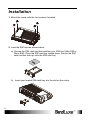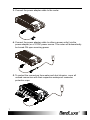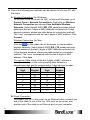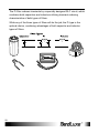
1
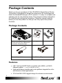
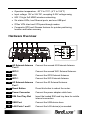
User Manual BandLuxe K530 Series LTE M2M&Vehicle Mount Router P/N:64003700011 Rev.D Table of Contents Features .................................................................................................................. 3 Hardware Overview................................................................................................. 4 Status .................................................................................................................... 10 System Log .......................................................................................................... 11 GPS ..................................................................................................................... 12 Traffic Monitor ...................................................................................................... 12 Mobile Internet ..................................................................................................... 13 System ................................................................................................................. 14 General Settings .......................................................................................................... 14 Language and Style ..................................................................................................... 14 Backup / Flash Firmware ...................................................................................... 16 Download backup ........................................................................................................ 16 Reset to defaults .......................................................................................................... 16 Restore backup............................................................................................................ 17 Flash new router firmware image ................................................................................ 17 Flash new module firmware image .............................................................................. 17 Flash new ipkg image .................................................................................................. 17 FOTA............................................................................................................................ 17 Reboot ................................................................................................................. 18 Dynamic DNS ....................................................................................................... 19 Network ................................................................................................................. 20 Interfaces ............................................................................................................. 20 Network Settings .......................................................................................................... 22 Auto APN Information .................................................................................................. 23 APN Profile Settings .................................................................................................... 23 Reset Modem .............................................................................................................. 23 Router .................................................................................................................. 24 Router IP ...................................................................................................................... 24 DHCP Service .............................................................................................................. 25 Active DHCP Leases ................................................................................................... 26 Static Leases ............................................................................................................... 26 Static Routing ............................................................................................................... 27 Routing and Redirection Service ................................................................................. 28 VPN Passthrough ........................................................................................................ 28 WiFi ...................................................................................................................... 29 Advanced Settings ....................................................................................................... 31 General Setup .............................................................................................................. 32 Wireless Security ......................................................................................................... 32 MAC-Filter .................................................................................................................... 36 Advanced Settings ....................................................................................................... 37 Firewall ................................................................................................................. 38 Single Port Forward ..................................................................................................... 38 Port Trigger .................................................................................................................. 40 Firewall......................................................................................................................... 42 Internet Filter ................................................................................................................ 42 Web Filters ................................................................................................................... 43 Network Filtering .......................................................................................................... 44 Port Range Forward .................................................................................................... 46 UPNP ................................................................................................................... 48 Advanced ............................................................................................................. 49 Diagnostics........................................................................................................... 49 Ping .............................................................................................................................. 49 1 Traceroute .................................................................................................................... 49 NS Lookup ................................................................................................................... 50 Help ...................................................................................................................... 51 Logout .................................................................................................................. 51 Overview .............................................................................................................. 52 Installation ............................................................................................................ 54 General Guidelines ............................................................................................... 54 Power Management ............................................................................................. 56 Power Management with Filter ............................................................................. 57 Europe – EU Declaration of Conformity................................................................ 70 Federal Communication Commission Interference Statement .............................. 71 Glossary ............................................................................................................... 73 2 Package Contents Package Contents Thank you for your purchase of this LTE M2M & Vehicle Mount Router. This product is designed to access the Internet via 4G technology and share the bandwidth through a Wi-Fi network. It is easy to configure and operate even for non-technical users. This manual contains instructions for installing and configuring the product. Read the manual carefully before you use the product, so that you can fully exploit the product functions. Package Contents BandLuxe K530 LTE/HSPA+ WiFi Router with GPS and Waterproof Connector Protective Caps Mounting Screws Power Adapter Power Adapter Cable Mini-SIM Card Tray Features • LTE* Cat3 and 3GPP Rel9 compatible with HSPA+ or EVDO fallback support (*: LTE is a trademark of ETSI.) • High performance module and router platform targeted for m2m and mission critical applications • IP 64 and MIL 810G rugged design for extreme environments 3 Package Contents • Operation temperature: -20°C to 70°C (-4°F to 158 °F) • Input voltage: 12V or 24V DC, accepting 9-32V voltage swing • 802.11 b/g/n 2x2 MIMO wireless networking • Six status LEDs, two Ethernet ports, and one USB port • IPSec VPN client and VPN pass-through modes • Composite GPS and Glonass features for quicker positioning location and better accuracy Hardware Overview 1 4G External Antenna Port 2 Connect the second 4G External Antenna. 2 WiFi 2 Connect the second WiFi External Antenna. 3 GPS Connect the GPS External Antenna. 4 WiFi 1 Connect the WiFi External Antenna. 5 4G External Antenna Port 1 Connect the 4G External Antenna. 6 Reset Button Press this button to reboot the router. 7 Power Connector Connect the power adapter cable here. 8 SIM Card Tray Slot Insert the loaded SIM card tray here for mobile internet connection. 9 USB Port Connect the USB device here. 10 LAN Ports 1 and 2 4 Connect the LAN device(s) as needed. Package Contents 11 Network Status LEDs 11-1 GPS Blue – GPS is ON. (Solid) Position is fixed. (Flashing) Position is not yet fixed. 11-2 LAN 2 Blue – LAN Port 2 is transmitting. 11-3 Signal Strength Blue – Good signal strength Green – Normal signal strength Red – 5 Poor signal strength or no signal 11-4 Network Status Blue – LTE connection (Solid) Connection is established. (Flashing) Connection is not yet established. Green – 3G connection (Solid) Connection is established. (Flashing) Connection is not yet established. Red – No mobile internet connection 11-5 LAN 1 Blue – LAN Port 1 is transmitting. 11-6 WiFi Blue – WiFi is ON. Installation Installation 1. Mount the router with the four screws if needed. 2. Load the SIM card as shown below: a) Choose the SIM card tray that matches your SIM card (Mini-SIM or Micro-SIM). Place the SIM card tray upside down. Secure the SIM card (contact side up) onto the SIM card tray. b) Insert your loaded SIM card tray into the slot on the router. 6 Installation 3. Connect the power adapter cable to the router. 4. Connect the power adapter cable to either a power outlet (via the power adapter) or a 12VDC power source. The router will automatically be turned ON upon receiving power. 5. To protect the connectors from water and dust intrusion, cover all unused connectors with their respective waterproof connector protective caps. 7 Installation 6. One of the following two methods can be chosen to link your PC with the router. A. Wireless Connection (for Windows) To link your PC to the router via WiFi, in Microsoft Windows, go to Control Panel > Network Connections. Right click on Wireless Network Connection and choose View Available Wireless Networks. Select default SSID [BR_LTE_xxxx] and enter default password (the last 4 digits of MAC address converted into 2-digit decimal numbers, please see table below for conversion method). The “xxxx” corresponds with the last 4 digits of MAC address. Click Connect. Wireless Connection (for Mac) Click the on the upper side of the screen to view available wireless networks. Select default SSID [BR_LTE_xxxx] and enter default password (the last 4 digits of MAC address converted into 2-digit decimal numbers, please see table below for conversion method). The “xxxx” corresponds with the last 4 digits of MAC address. Click Join. Conversion Table: Each of the last 4 digits of MAC address is hexadecimal. Here is the corresponding table between a hexadecimal digit and its corresponding 2-digit decimal number: Hexadecimal Decimal Hexadecimal Decimal Digit Number Digit Number 0 00 8 08 1 01 9 09 2 02 A 10 3 03 B 11 4 04 C 12 5 05 D 13 6 06 E 14 7 07 F 15 B. Wired Connection To connect your PC to the router via an Ethernet cable, connect one end of the cable to one of the four LAN ports on the router, and another end of the cable to an Ethernet port on your computer. 8 Using Web-based Management Using Web-based Management This chapter will guide you on how to configure your router via the web-based utility. Login 1. Launch a web browser (e.g Mozilla Firefox). 2. In the address bar, enter http://192.168.1.1, then press Enter. 3. On the opening screen, enter the username (admin) and password (admin). 4. Click Login to login to the main screen. 5. Click one of the menu, submenu, and/or setting tabs to configure the system. Additionally, the status area displays current wireless network information and setting-related messages (e.g. the message Unapplied Change appears whenever new settings are temporarily stored in the router without being applied, which will remind you to click the button). status area menu submenu setting 9 Using Web-based Management Status This menu displays various statuses of the router. The associated submenu items are: Overview, System Log, VnStat Traffic Monitor, and Mobile Internet. Overview The Overview submenu renders complete statistics for the router. 10 Using Web-based Management System Displays system information: router model name, router firmware version, modem firmware version, phone number (MDN), ICCID, MIN (MSID), PRL version, IMEI, MEID, and local time. Network Displays current network connection information of IPv4 WAN and/or IPv6 WAN: type of network assignment (e.g. DHCP), network address, netmask, gateway, DNS addresses 1 & 2, and time connected since the establishment of the current mobile internet connection. DHCP Leases Display DHCP lease information for each client: hostname, IPv4 address, MAC address, and lease time remaining. Local Network Displays local network information: local MAC address, router IP address, subnet mask, DHCP server, DHCP server change, start IP address, IP and address range System Log The System Log submenu tracks system activities after power on. 11 Using Web-based Management GPS The GPS submenu displays Global Positioning System information. Click to proceed. Traffic Monitor The Traffic Monitor submenu displays analysis of the router’s network traffic history. 12 Using Web-based Management Mobile Internet The Mobile Internet submenu displays mobile internet statistics. Signal Quality Displays signal strength of current mobile internet connection in dBm. UICC/SIM Status Displays current SIM card status: a) Read SIM Fail – No valid SIM card is inserted Registered Network a) Network Name – name of your mobile internet service provider b) Network Technology – mobile internet communication signal type. Examples are WCDMA (3G) and LTE (4G). c) Home/Roaming – displays current network roaming status: Home indicates mobile internet connection to the home location where the SIM card service is registered. Roaming indicates the extended mobile internet connection service in a location different from the home location where the SIM card service is registered. An example of roaming is when you travel abroad. 13 Using Web-based Management Internet Connection Displays information of current internet connection: Connection Type, Internet IP Address, Gateway, and DNS 1/2. System This menu is for system information and configurations. System System Properties Click either the “General Settings” or “Language and Style” tab to configure their respective settings. General Settings Local Time – Displays current local time. To synchronize local time with the browser, click . Hostname – Enter the desired hostname in this check field. Time Zone – Sets the time zone associated with this router. Click on and select the desired region. Language and Style 14 Using Web-based Management Language – Sets the desired display language and style of the router. Click and select the desired display language and style. Time Synchronization Enable NTP client: Click the checkbox to enable/disable. With this option enabled, two more options will appear– “Provide NTP server” and “NTP server candidates”. NTP server candidates 1/2: Enter the desired server candidates here. Remote System Log Router LAN client IP address: Displays the client IP address of the router LAN. Server port: Displays port number of the server. Administration Router Password Login password of the router can be changed here. Enter the new password in the ‘Password’ field, and enter the same password once again in the ‘Confirmation’ field. Remote Access This field specifies whether or not to allow remote access of this router. After changing password and/or specifying remote access, click The screen will display a confirmation message after successful password change. 15 . Using Web-based Management Backup / Flash Firmware Backup / Restore Download backup Here you can backup all current settings of the router to a TAR archive file . A dialog on your computer or mobile device. Just click window will prompt you to open or save the archive file. Depending on the browser that you are using, the TAR file may be saved in the system download folder or a location of your choice. Reset to defaults Here you can restore the router to its original factory settings. Just click 16 Using Web-based Management , and a dialog message will appear to indicate the factory reset process. After completion of the reset process, the router will automatically reboot and return to its initial login prompt. Restore backup Here you can restore router settings previously saved as a TAR archive to find and file on your computer or mobile device. Just click select the previously saved TAR archive file, and then click ‘Open’. Confirm that the TAR filename appears beside the button and click . The system will reboot after completion of backup restoration. Flash new router firmware image This option allows you to upgrade this router with the updated firmware image. Just click to find and select the firmware image file, and then click ‘Open’. Confirm that the firmware filename appears beside the button and click . The system will reboot after successful upgrade. Flash new module firmware image This option allows you to upgrade this router with the updated module to find and select the firmware firmware image. Just click package file, and then click ‘Open’. Confirm that the firmware filename appears beside the button and click . The system will reboot after successful upgrade. Flash new ipkg image This option allows you to upgrade this router with the updated IPKG to find and select the IPKG package file, package. Just click and then click ‘Open’. Confirm that the IPKG package filename appears beside the button and click . The system will reboot after successful upgrade. FOTA This option (Firmware Over The Air) allows you to do upgrade automatically or manually router’s firmware wireless. For automatic wireless update, enable “Auto check” and enter the desired time interval (in hours) between each check of the BandRich website for 17 Using Web-based Management firmware update. For manual wireless update, disable “Auto check”. to activate the wireless update configurations into effect. Click To immediately check for firmware upgrade, click Check. Warning: Upgrading firmware may take up to 50 minutes depends on internet download speed; do not turn off the power or press the Reset button during upgrade. Reboot Click ‘Perform reboot’ to restart the router. 18 Using Web-based Management Services Dynamic DNS The Services menu hosts configuration options for DDNS (Dynamic Domain Name Service), which is a system that allows the domain name data held in a name server to be updated in real time. It allows an Internet domain name to be assigned to a computer with a varying (dynamic) IP address. Before you can use this feature, you need to sign up for DDNS with a DDNS provider, www.dyndns.org or www.TZO.com. Enable: Check or un-check this box to enable or disable DDNS. Service: Specifies the DDNS service URL. From the drop-down list, click and select an URL from the list. Hostname: Enter the hostname for your DDNS account. Username: Enter the username for your DDNS account. Password: Enter the password for your DDNS account. 19 Using Web-based Management Network Interfaces The Interfaces submenu allows interface configurations of different networks connected to this router. The configuration items are the same for each network with different default settings. Interface Overview Here you can see the brief network status summary for LAN (local area network) and WAN (wide area network). To configure LAN or WAN interfaces, click the appropriate Edit button and follow the below section Common Configuration for more details. 20 Using Web-based Management Mobile Internet The Mobile Internet submenu is for setup and adjustment of mobile internet connection and furthermore has four setting tabs: WWAN Setting, and Preferred Network. 21 Using Web-based Management WWAN Setting Network Settings 22 Roaming Connection: Enables or disables current roaming setting. Update Profile: Click Update to update the network profile. Update PRL: Click Update to update the PRL (Preferred Roaming List). APN Update: Displays the current APN (Access Point Name) version. To get the latest version of APN, click . APN: ‘Auto’ – Uses automatic APN profile settings for network; this is the default APN setting. ‘Manual’ – Allows the manual choice of APN Profile Using Web-based Management Settings for network. Profile Selection: This item appears when APN is set to ‘Manual’. Auto APN Information This section displays automatic APN information. APN Profile Settings For Advanced Users This section allows you to establish your own APN profile settings. To establish a new APN profile, type in a new APN profile name in the text . box and click Enter the APN, username, and password. Click . Reset Modem Click Perform reset to reset this router to its factory default settings. Preferred Network and Here you can select the preferred mobile network type by clicking making a choice from the drop-down list. The default choice is Auto. 23 Using Web-based Management Router Router Settings Router IP Local IP Address: The default local IP address of this router is 192.168.1.1. If this address conflicts with another local network device, you can enter another local IP address here. 24 Subnet Mask: Displays current Subnet Mask Device Name: The current device name is displayed in gray color. The device name can be changed by typing in the new device name in this text box. MTU: The current MTU (maximum transmission unit with default value of 1422 bytes) is displayed in gray color. The MTU can be changed by typing in the new MTU value in this text box. Using Web-based Management DHCP Service DHCP Server: Enables or disables the DHCP Server feature. Start IP Address: Specifies the starting number of the last 3 digits of assigned client IP address. For example, the default value of 100 means that the first assigned client IP address will be 192.168.1.100; the next assigned client IP address will be 192.168.1.101; and so on… Maximum Specifies maximum number of users for this router. Number of Users: The default setting is 150 users. 25 Client Lease Time: Specifies the amount of lease time allocated to clients of this router, i.e. the expiry time of leased addresses. Use ‘h’ to indicate hours or use ‘m’ to indicate minutes. IP Address Range: Displays assignable local IP address range of this router Primary DNS: If needed, specify the primary Domain Name System here. Secondary DNS: If needed, specify the secondary Domain Name System here. Using Web-based Management Active DHCP Leases This section displays active DHCP lease information for each client: Hostname, IPv4 address, MAC address, and Lease time remaining. Static Leases This option allows fixed IP address and symbolic hostname assignments for DHCP clients. To add a static lease, first click . Enter the desired hostname. Choose the desired MAC address and and select a rule from the drop-down list; if IPv4-Address (click “--Custom--" is selected, the drop-down list will change to a text box to allow you to enter your custom address). The MAC address is for host identification, whereas the IPv4 address specifies the fixed address for static lease. To remove any unwanted static lease, just click the corresponding button. Click 26 after making any changes. Using Web-based Management Advanced Routing settings Static Routing This option allows fixed network routing path assignment (as opposed to the initial adaptive routing). To add a static network routing path, click . To remove any unwanted static network routing path, click the corresponding after making any changes. button. Click 27 Interface: and choose ‘lan’ (local area network) or Click ‘wan’ (wide area network). Target: Enter the target host IP or network address here. IPv4-Netmask: Displays the IPv4-Netmask address (the default is 255.255.255.255). A custom IPv4-Netmask can also be specified here. IPv4-Gateway: If needed, a custom IPv4-Gateway address can be Using Web-based Management specified here. Metric: Specifies the network path priority number (usually associated with the network path’s administrative distance). The lower the metric number, the higher priority of this static route in the network routing protocol. The default value is 0 (highest priority). A different metric number can also be specified here. Note: If contents in the text box is invalid, a will appear on the right side of the text box, and the text color changes to red. For example, the following demonstrates an invalid target Host-IP or Network address: Routing and Redirection Service This option allows the user to choose between NAT, RIP, BGP or OSPF. VPN Passthrough A Virtual Private Network (VPN) is a type of secured private network connection, built upon publicly-accessible infrastructure such as the Internet. They usually provide connectivity to various devices behind a gateway or firewall. IPSec Passthrough: IP Security (IPSec) provides authentication and encryption. Since it is mainly a Layer 3 technology, it can secure all data on the network. To allow IPSec tunnels to pass through the Router, click ‘Enabled’. PPTP Passthrough: Point-to-Point Tunneling Protocol (PPTP) allows you to establish a connection to an enterprise network. To allow PPTP tunnels to pass through the Router, click Enabled. Layer 2 Tunneling Protocol (L2TP) is an extension of the Point-to-Point Tunneling Protocol and is also used to establish virtual private networks. To allow L2TP tunnels to pass through the Router, click Enabled. L2TP Passthrough: 28 Using Web-based Management WiFi This submenu item is for configuring all Wi-Fi-related settings. This router supports up to two WiFi SSIDs. The default SSID is as follows: Tab Name Corresponding SSID Default Password “BR_LTE_xxxx” BR_LTE_xxxx The last 4 digits of MAC address (xxxx) converted into 2-digit decimal numbers, please see table below for conversion method. Hexadecimal Decimal Hexadecimal Decimal Digit Number Digit Number 0 00 8 08 1 01 9 09 2 02 A 10 3 03 B 11 4 04 C 12 5 05 D 13 6 06 E 14 7 07 F 15 SSID and Password Example: MAC Address Corresponding SSID Default Password 0026FA0B314A BR_LTE_314A 03010410 Each tab has identical sets of configuration categories: Device Configuration and Interface Configuration. Please click after making any changes in this submenu. 29 Using Web-based Management Device Configuration General Setup or Wireless network is enabled* WiFi connection of the associated SSID is enabled. Wireless network is disabled* WiFi connection of the associated SSID is disabled. . To disable WiFi connection of this SSID, click To enable WiFi connection of this SSID, click . * Note: The associated SSID is displayed either in the selected submenu tab under WiFi or in the WiFi category item Interface Configuration General Setup SSID. Channel: Selects the WiFi channel for communication. The available choices are: Channel (carrier frequency) 1 (2.412 GHz) 2 (2.417 GHz) 3 (2.422 GHz) 4 (2.427 GHz) 5 (2.432 GHz) 30 Using Web-based Management 6 (2.437 GHz) 7 (2.442 GHz) 8 (2.447 GHz) 9 (2.452 GHz) 10 (2.457 GHz) 11 (2.462 GHz) auto -- custom -- assigns channel automatically manually specifies WiFi channel Normally one of the channels is already selected, and no change is needed unless there exists interference problems with other WiFi or Bluetooth devices (that also use the 2.4GHz frequency range for communications). Alternatively, you can select ‘auto’ to let the system select the channel automatically, or you can select “-- custom --” and enter your own channel specification in the text box. Advanced Settings Mode Specifies the IEEE wireless standard for WiFi communication. The choices are: Auto: (Default choice) The router automatically chooses the optimal IEEE wireless standard. 802.11b: Data speed up to 11 Mbps 802.11g: Data speed up to 54 Mbps 802.11n: Data speed up to 300 Mbps HT mode Specifies channel width for data communications. The choices are: 20MHz: Single 20MHz channel 20MHz / 40MHz Single or dual 20MHz channels Click to activate the second SSID, or click to deactivate the second SSID. Dual SSID is disabled/enabled 31 Using Web-based Management Interface Configuration General Setup SSID Service Set Identification To change the SSID, click the text box and enter the new SSID (up to 32 alphanumeric characters) Mode Wireless operating mode of this router. AP: Wireless Access Point Hide SSID Enable this option to make wireless network of this SSID unavailable to nearby WiFi clients. Disable this option to make wireless network of this SSID available to nearby WiFi clients (default setting). CAUTION: To enable “Hide SSID”, we strongly advise you to do so via wired LAN connection, since wireless LAN connection with this SSID will be lost with this option applied! If both SSIDs are hidden, then the communications with this router must be done via a LAN port, or this router must be reset to factory default settings. Wireless Security This router supports wireless data encryption, a must for wireless data security. The Wireless Security Interface Configuration items will change according to the chosen encryption method. 32 Using Web-based Management The encryption options are: 1. No Encryption Data transmitted over wireless networks can be seen by others. 2. WEP Open System Wired Equivalent Privacy encryption with Open System authentication Key: Enter a password for accessing this SSID’s wireless network. 3. WPA-PSK “WiFi Protected Access – Pre-Shared Key” encryption Cipher: Specify the desired encryption protocol by clicking selecting an option from the drop-down list: and auto – (default setting) the system automatically chooses the optimal encryption protocol Force CCMP (AES) – Use CCMP (AES) encryption exclusively (stronger than TKIP) Force TKIP – Use TKIP encryption exclusively Force TKIP and CCMP (AES) – Use TKIP and CCMP (AES) encryption protocols together Key: Enter a password for accessing this SSID’s wireless network. 4. WPA2-PSK “WiFi Protected Access II – Pre-Shared Key” encryption 33 Using Web-based Management Cipher: Specifies the desired encryption protocol by clicking selecting an option from the drop-down list: and auto – (Default setting) the system automatically chooses the optimal encryption protocol Force CCMP (AES) – Use CCMP (AES) encryption exclusively (stronger than TKIP) Force TKIP – Use TKIP encryption exclusively Force TKIP and CCMP (AES) – Use TKIP and CCMP (AES) encryption protocols together Key: Enter a password for accessing this SSID’s wireless network. 5. WPA-PSK/WPA2-PSK Mixed Mode “WiFi Protected Access I + II – Pre-Shared Key” encryption Cipher: Specifies the desired encryption protocol by clicking selecting an option from the drop-down list: and auto – (Default setting) the system automatically chooses the optimal encryption protocol Force CCMP (AES) – Use CCMP (AES) encryption exclusively (stronger than TKIP) Force TKIP – Use TKIP encryption exclusively Force TKIP and CCMP (AES) – Use TKIP and CCMP (AES) encryption protocols together Key: 34 Enter a password for accessing this SSID’s wireless network. Using Web-based Management 6. WPA-EAP “WiFi Protected Access – Extensible Authentication Protocol” encryption Cipher: Specifies the desired encryption protocol by clicking selecting an option from the drop-down list: and auto – (default setting) the system automatically chooses the optimal encryption protocol Force CCMP (AES) – Use CCMP (AES) encryption exclusively (stronger than TKIP) Force TKIP – Use TKIP encryption exclusively Force TKIP and CCMP (AES) – Use TKIP and CCMP (AES) encryption protocols together Radius-Authentication-Server: authentication server. Enter the name of the RADIUS Radius-Authentication-Port: Enter the port number of the RADIUS authentication port (the default port number is 1812). Radius-Authentication-Secret: Enter the desired RADIUS secret password. 7. WPA2-EAP “WiFi Protected Access II – Extensible Authentication Protocol” encryption 35 Using Web-based Management Cipher: Specifies the desired encryption protocol by clicking and selecting an option from the drop-down list: auto – (default setting) the system automatically chooses the optimal encryption protocol Force CCMP (AES) – Use CCMP (AES) encryption exclusively (stronger than TKIP) Force TKIP – Use TKIP encryption exclusively Force TKIP and CCMP (AES) – Use TKIP and CCMP (AES) encryption protocols together Radius-Authentication-Server: authentication server. Enter the name of the RADIUS Radius-Authentication-Port: Enter the port number of the RADIUS authentication port (the default port number is 1812). Radius-Authentication-Secret: password. Enter the desired RADIUS secret MAC-Filter MAC-Address Filter: This tab item allows you to selectively allow or block clients from network access. Click and select an option from the drop-down list: 1. Disable – The MAC address filter is disabled (default option). and select a desired MAC address from the 2. White list* – Click drop-down list, or select “-- custom --" and enter a specific client’s MAC address. 3. Black list* – Click and select an undesired MAC address from the drop-down list, or select “-- custom --" and enter a specific client’s MAC address. * 36 To add another MAC address to the list, click to add a new drop-down list; then repeat the MAC address selection/specification. To remove a MAC address from the list, click . Using Web-based Management Advanced Settings This tab item is for advanced adjustment settings for WiFi connection. 37 Fragmentation Threshold Maximum transmittable data packet frame size without frame fragmentation; the default value is 2346 RTS/CTS Threshold Defines Request-To-Send (transmitter) and Clear-To-Send (receiver) control packet size; the default value is 2347 WMM Mode Enables or disables Wi-Fi Multimedia Mode, which gives multimedia data contents (voice, video, and audio) higher priority over wireless networks. The default setting of WMM Mode is Disabled. Using Web-based Management Firewall Single Port Forward Single Port Forward Port Forwarding allows you to set up public services on your network, such as web servers, ftp servers, e-mail servers, and other specialized Internet applications. To forward a single port: 1. Name: Enter an application name for this port forwarding rule. 2. Protocol: Click and select a protocol from the drop down list – TCP+UDP (default), TCP, UDP, or Other… 3. External port: Enter the port number of the external port used by the server or Internet application. Afterward, this port number will be echoed to the text box of “Internal port”. and select an IP address from 4. Internal IP address: Click drop-down list, or select “--custom--" and enter IP address in text box. 5. Internal port: This text box will automatically receive port number entered in the text box of “External port”, or you can enter your own port number in the same text box. 6. Click . The port forwarding rule you have just entered will be added to the Port Forwards list. 38 Using Web-based Management (a) (b) In the status area, the message Unapplied Change may appear next to “Operator Name” to indicate configuration changes temporarily stored in the router. 7. More rules can be added to the Port Forwards list by repeating Steps 1-6. 8. (a)To enable or disable a Port Forwards list rule, click its check box under ‘Enable’. (b) To remove any Port Forwards rule, click its corresponding button. 9. To edit a particular Port Forwards rule in detail, click its button, and the rule’s associated corresponding configuration page (much more flexible and detailed than express settings in Steps 1-5) will appear. After making any changes, click . Finally click to exit this configuration page. Note: 39 Numerical and text values shown in the illustrative examples are for demonstration purposes only and are not for actual operation. Using Web-based Management Port Trigger Port Trigger Port Triggering allows the Router to watch outgoing data for specific port numbers. The Router remembers the IP address of the computer that sends the matching data, so that when the requested data returns through the Router, the data is pulled back to the proper computer by way of IP address and port mapping rules. To add a new Port Triggering rule: 1. Name: enter an application name for this port triggering rule. and select a protocol from the drop down list – 2. Protocol: click TCP+UDP (default), TCP, UDP, or Other… 3. Triggered Range: enter the Start Port and End Port for the triggered port number range of the Internet application (please check its documentation for the port number(s) needed). 4. Forwarded Range: enter the Start Port and End Port for the forwarded port number range of the Internet application (please check its documentation for the port number(s) needed). 40 Using Web-based Management 5. Click . The port triggering rule you have just entered will be added to the Port Triggering list. (a) (b) In the status area, the message Unapplied Change may appear next to “Operator Name” to indicate configuration changes stored in the router. 6. More rules can be added to the Port Triggering list by repeating Steps 1-5. 7. (a) To enable or disable a Port Forwards list rule, click its check box under ‘Enable’. (b) To remove any Port Triggering rule, click its corresponding button. 8. To edit a particular Port Triggering rule in detail, click its button, and the rule’s associated corresponding configuration page (more flexible and detailed than express settings in Steps 1-4) will appear. After making any changes, click . Finally click to exit this configuration page. Note: 41 Numerical and text values shown in the illustrative examples are for demonstration purposes only and are not for actual operation. Using Web-based Management Security Filter Here you can make Firewall, Internet Filter, and Web Filters adjustments for network security. Firewall SPI Firewall Protection: Enable or Disable Stateful Packet Inspection (SPI) feature of the firewall. The default setting is ‘Enable’. Internet Filter Filter Anonymous This filter blocks anonymous internet requests from Internet Requests: outside network. The default setting is ‘disabled’. Filter Multicast: 42 Multicasting allows for multiple transmissions to specific recipients at the same time, i.e. the Router allows IP multicast packets to be forwarded to the appropriate computers. To allow multicasting, disable “Filter Multicast” (this is the default setting). To block multicasting, enable “Filter Multicast”. Using Web-based Management Filter Internet NAT This filter blocks local resource access via NAT Redirection: (Network Address Translation) redirection (i.e. external address) from other local computers. The default setting is ‘enabled’. Filter IDENT (Port113): This feature keeps Port 113 from being scanned by devices outside of your local network. The default setting is ‘disabled’. Web Filters Using the Web Filters feature, you may enable up to four specific filtering methods. Proxy: Use of WAN proxy servers may compromise the Router's security. Select this option to disable access to any WAN proxy servers. Java: Java is a programming language for websites. Select this option to disable Java. If you disable Java, you run the risk of not having access to Internet sites created using this programming language. ActiveX: ActiveX is a programming language for websites. Select this option to disable ActiveX. If you disable ActiveX, you run the risk of not having access to Internet sites created using this programming language. Cookies: A cookie is data stored on your PC and used by Internet sites when you interact with them. Select this option to disable cookies. DMZ Host When a firewall is used, it is sometimes necessary to place some clients (for example Internet games, video conferencing, or VPN connections) 43 Using Web-based Management outside of the firewall while leaving the others protected. You can do this using a Demilitarized Zone (DMZ). This DMZ Host feature allows you to specify the IP address of the computers that are placed outside the firewall of your network. In the text box, enter the last 3 digits of the DMZ host address (the prefix is 192.168.1 for this router), and then click . The host IP address will be added to the DMZ Host list, which can be further disabled or enabled by clicking the ‘Enable’ checkbox. To remove . After setting up the DMZ host, click . this DMZ Host, click Network Filtering Network Filtering Network Filtering allows the Router to discard data from certain IP addresses. To add a new Network filtering rule: 1. Name: Enter an application name for this Nerwork filtering rule. and select a protocol from the drop down list – 2. Protocol: Click TCP+UDP (default), TCP, UDP, or Other… 3. Filter Source IP Address: Enter the source IP address to be on the right for any filtered. The text color will turn red with 44 Using Web-based Management invalid IP address entered (e.g. ). When the IP address entered becomes valid, the text color changes back to on the right (e.g. ). black without 4. Filter Source Port: Enter the source port number to be filtered. . The Nerwork filtering rule you have just entered will be 5. Click added to the Nerwork filtering list. (a) (b) In the status area, the message Unapplied Change may appear next to “Operator Name” to indicate configuration changes stored in the router. 6. More rules can be added to the Nerwork filtering list by repeating Steps 1-5. 7. (a) To enable or disable an Nerwork filtering list rule, click its check box under ‘Enable’. (b) To remove any Port Triggering rule, click its corresponding button. 8. To edit a particular Network filtering rule in detail, click its button, and the rule’s associated corresponding configuration page (more flexible and detailed than express settings in Steps 1-4) will appear. After making any changes, click . to exit this configuration page. Finally click Note: 45 Numerical and text values shown in the illustrative examples are for demonstration purposes only and are not for actual operation. Using Web-based Management Port Range Forward Port Range Forward Port Range Forward allows you to set up public services on your network, such as web servers, ftp servers, e-mail servers, and other specialized Internet applications. To forward a port range: 1. Name: Enter an application name for this port range forwarding rule. 2. Protocol: Click and select a protocol from the drop down list – TCP+UDP (default), TCP, UDP, or Other… 3. Port Range Forward: Specify the range of port forwarding by entering the Start Port number and the End Port number. 4. IP address: Enter the IP address of the PC running the specific application. 46 Using Web-based Management 5. Click . The port range forwarding rule you have just entered will be added to the Port Range Forward list. (a) (b) In the status area, the message Unapplied Change may appear next to “Operator Name” to indicate configuration changes temporarily stored in the router. 6. More rules can be added to the Port Range Forward list by repeating Steps 1-5. 7. (a) To enable or disable a Port Forwards list rule, click its check box under ‘Enable’. (b) To remove any Port Forwards rule, click its corresponding button. 8. To edit a particular Port Forwards rule in detail, click its button, and the rule’s associated corresponding configuration page (more flexible and detailed than express settings in Steps 1-4) will appear. After making any changes, click . Finally click to exit this configuration page. Note: 47 Numerical and text values shown in the illustrative examples are for demonstration purposes only and are not for actual operation. Using Web-based Management UPNP Universal Plug and Play – Allows wired and wireless network devices to discover each other and establish network services. UPnP Settings Here you can ‘Enable’ or ‘Disable’ the UPnP service. 48 Using Web-based Management Advanced Diagnostics This menu contains tools for effective network analysis and troubleshooting. Network Utilities Ping This feature allows you to check the status of a connection. 1. In the text box next to want to ping. , enter the IP address or URL that you 2. In the text box of “Packet Size”, enter the desired value (default packet size is 56). 3. In the text box of “Number of Pings”, enter the number of times you wish to ping (default value is 5). to begin the connection status check. ‘Ping’ messages 4. Click will appear below. Traceroute This feature allows you to check the performance of a connection. 49 Using Web-based Management 1. In the text box next to , enter the IP address or URL that you to start the performance want to trace route, and then click text. ‘Traceroute’ messages will appear below. NS Lookup This feature allows you to retrieve name server information. 1. In the text box next to , enter the IP address or URL that you to get name server want to trace route, and then click information. ‘Nslookup’ messages will appear below. 50 Using Web-based Management Help Click the appropriate download link to download the latest Quick Start Guide or User Manual of this product. Logout Exits the web configuration interface and re-directs to login prompt. Note: 51 After a period of inactivity, automatic logout will occur. After clicking any menu item, the login prompt will appear as re-login is needed to continue using the web configuration interface. Appendix A: Vehicle Installation Guide Appendix A: Vehicle Installation Guide Overview Your K530 is designed for rugged vehicle use with IP64 and MIL810G compliances. The IP64 rating ensures that your K530 is dust-tight and is well-protected against liquid intrusion. The MIL810G rating ensures that your K530 is well-guarded against tough environmental and climate conditions. To ensure proper operation of K530, a stable power supply is essential in addition to secure mount. However, getting a stable power supply from an operating vehicle can be a major challenge. Due to constantly changing vehicle and environmental conditions, as well as different circuit loadings due to different stages of vehicle operation and use of its onboard electronic products, the raw voltage supplied by a vehicle’s battery may vary largely. Therefore, if untreated, vehicular electrical systems are generally harsh for electrical equipment onboard. There are two types of voltage supply problems in a vehicle. One is called brown-out voltage problem, and the other is called transient voltage problem. Brown out usually occurs during the start of the engine. In general, when 52 Appendix A: Vehicle Installation Guide the car engine starts, the spark plug draws significant stream of instantaneous electrical power from the car battery (ultra high instantaneous electrical current in terms of hundreds of cranking amps or more), leaving not much instantaneous electrical energy useful for other electrical equipment on the vehicle, therefore the voltage supplied to other electrical equipment drops significantly lower than its normal level. It is after such instantaneous high demand of electrical power that the voltage level returns to normal. The diagram below demonstrates the brown-out phenomenon when the engine is starting. Transient voltage, sometimes known as spikes, is generally very noticeable positive or negative voltage changes over a short period of time. Such voltage fluctuations may be occasional or may be periodic. The fluctuations are typically caused by interference from the electrical-mechanical components in the vehicle (alternators, electric windows and door locks, light switches, loose or corroded connectors or battery terminals, etc.), or even from additional electrical equipment connected to the vehicle’s electrical power system. Without treatment, sharp spikes are a potential threat to your K530 as well as other electrical equipment on the vehicle. The diagram below shows some standardized examples of automotive voltage transients (ISO-7637-2): 53 Appendix A: Vehicle Installation Guide Your K530 is designed to handle large voltage swings from 9V to 32V, in case of undesirable voltage transients or brown-outs. However, for best use and proper protection of your K530, it is necessary to regulate input voltage before feeding it to the power input of your K530. There are two ways of electrical voltage regulation. One way is to implement a power management block that harnesses battery power during engine startup. The more effective way is to implement a power management block with filters that further smoothes out residual spikes. Installation General Guidelines Follow these guidelines for optimal vehicle installation of your K530: 1. Place the router as close to the voltage regulators, such as power management block and filters, as possible. In other words, keep the power cables short between the router and the output connectors of the voltage regulators. 2. Use the proper wire size according to the expected current load. Please see the table below: 54 Appendix A: Vehicle Installation Guide AWG Rating Electric Current Load (Amps) 10-Feet Cable 20-Feet Cable 3-10 14 AWG 12 AWG 11-20 14 AWG 10 AWG 21-35 8 AWG 6 AWG 3. To avoid problems caused by corrosion and other imperfections, use a dedicated ground wire instead of direct attachment to chassis ground. 4. To minimize noise interference, implementation of isolation or filters among the router and other electrical devices is recommended. 5. Ensure that your K530 is securely mounted on the vehicle. In addition to electrical requirements, also consider vibration and temperature factors when choosing the optimal location for mounting your K530. If vibration problem is noticeable, anti-vibration rubber grommets may be used to reduce shock on your K530. Also avoid mounting your K530 near a spot subject to extreme heat, such as a poorly ventilated spot that is near the engine or is prone to direct sunlight. 6. To connect the device to USCC network, antennas connection to LTE1 and LTE2 ports are required. 7. To utilize WiFi connection, antennas connection to WiFi1 and WiFi2 ports are required. 8. To utilize both LTE/CDMA and WiFi, all four antennas connection are required. 9. GPS antenna is not mandatory unless LBS functionality is needed. 10. If only 1 antenna is connected to LTE/CDMA or WiFi, please always connect the antenna to LTE1 and WiFi1. Wireless performance is degraded in such scenario. 55 Appendix A: Vehicle Installation Guide Power Management In this type of installation, voltage regulation is done solely on the power management block, which routes battery power to the ignition switch during engine startup, while rendering conditioned output DC power to the vehicle’s electrical parts. First connect the long positive red power cable to the input of power management block, then connect the conditioned positive power output to your K530. On the ground side, connect the ground from your K530 together with the ground of the power management block and the ground of the battery. 56 Appendix A: Vehicle Installation Guide Power Management with Filter In this type of installation, voltage regulation is done in two parts. The first part is on the power management block, which routes battery power to the ignition switch during engine startup while rendering conditioned output DC power to the vehicle’s electrical parts. First connect the long positive red power cable to the input of the power management block, then connect the conditioned positive power output to your K530. On the ground side, connect the ground from your K530 together with the ground of the power management block and the ground of the battery. The second part further conditions power voltage with the use of a filter, which can further smooth out residual transients left over by the power management block. There are three types of filters: capacitor, inductor, and Pi. The capacitor reduces transients by temporarily storing some electrical energy in the electrostatic field (electrical capacitance caused by voltage differences between two plates with the dielectric material in between) and gradually releasing them over time. The inductor reduces transients by temporarily storing some electrical energy in the magnetic field (electrical induction caused by electric currents) and gradually releasing them over time. 57 Appendix A: Vehicle Installation Guide The Pi filter reduces transients by a specially designed RLC circuit, which combines both capacitors and inductors utilizing transient-reducing characteristics of both types of filters. While any of the three types of filters will do the job, the Pi type is the optimal choice, combining advantages of both capacitor and inductor types of filters. 58 Appendix B: FAQ Appendix B: FAQ Q: What should I know and how long does it take when I upgrade the firmware of router or modem? A: 1. While upgrading the firmware requires some time to finish. During that, you MUST NOT turn off the power or interrupt the progress. 2. You may use an Ethernet cable or a wireless connection to upgrade the firmware. We suggest the use of an Ethernet cable. 3. It may take 2 minutes to upgrade the firmware of the router and 5 minutes to upgrade the firmware of the modem. Time of download the firmware depends on internet speed. 4. When the firmware of the modem is upgrading, the UMTS LED will flash among Blue-Green-Red. You should wait until the LED is in single color (about 4-5 minutes). Q: How do I connect to the router? A: 1. Connect an Ethernet cable between PC/Notebook (NB) and the router. 2. Use WiFi to connect. Q: What’s the default “User name” and “Password” for the router? A: User name: admin Password: admin Q: How do I enter GUI and setup the configuration for the router? A: 1. Connect PC/NB to the router. 2. Open Internet Explorer or other Web browser. 3. Input “http://192.168.1.1”. 4. Input User name and Password. Q: Why can’t I connect to the network via built-in 3G module? A: 1. Check the SIM/USIM to see if it is inserted well. 2. Check the UMTS LED on the router to see if it is solid. 3. Check the Status on GUI to see if the SIM/USIM detected well. 4. Check the Status on GUI to see if the APN it is correct. 5. Check the Internet on GUI to see if the Connection is “Keep Alive” or not. Q: Why can't I link on the GUI? A: If you have changed your WiFi security, SSID, Local IP address, you have to repair your network to get a new IP that you can link the GUI. XP: 59 Appendix B: FAQ If you are a WiFi user, click Network Connections and right click on Wireless Network Connection, click Repair. If you use Local Area Connection to connect the Router, click Network Connections and right click on Local Area Connection, click Repair. Vista/7: 1. If you are a WiFi user, please click Network and Sharing Center > Manage network connections > Wireless Network Connection > Diagnose. 60 Appendix B: FAQ 2. Please click Reset the network adapter “Wireless Network Connection” and it will began to repair. 3. If you use Local Area Connection to connect the Router, please click Network and Sharing Center > Manage network connections > Local Area Connection > Diagnose, follow step 1 and the subsequent messages to repair it. Q: How do I configure my WiFi settings from GUI? A: Click the menu tabs Network Wi-Fi to access to the Wi-Fi submenu, and then click the submenu tab of a particular ESSID. If you want to configure WiFi Security please click the “Wireless Security” tab under “Interface Configuration”. There are seven wireless security encryption options supported by the Router: WEP Open System, WEP Shared Key, WPA-PSK, WPA2-PSK, WPA-PSK/WPA2-PSK Mixed Mode, WPA-EAP, and WPA2-EAP. 61 Appendix B: FAQ Q: How can I have a long-time link? A: Click the menu tabs Network Router Router Setting. Under “DHCP Service”, set Client Lease Time to a large value (e.g. 120h = 120 hours = 5 days). Q: Why can’t I use the router in the office? A: Your router’s IP address might conflict with the office default settings. Q: Why is my internet speed is so slow with the router? A: 1. Click the menu tabs Status Mobile Internet to check the Rx Signal Strength in dBm. Weak signals will significantly slow down internet speed. 62 LEDs ON Signal Strength 3G/2G/cdma2000 RSSI reading 4G LTE RSRP reading none 0 bars Weaker than -100 dBm Weaker than -115 dBm #12 1 bar -100 dBm to (just below) -95 dBm -115 dBm to (just below) -109 dBm #12to#13 2 bars -95 dBm to (just below) -90 dBm -109 dBm to (just below)) -103 dBm #12to#14 3 bars -90 dBm to (just below) -83 dBm -103 dBm to (just below) -95 dBm #12to#15 4 bars -83 dBm to (just below) -76 dBm -95 dBm to (just below) -87 dBm #12to#16 5 bars -76 dBm or stronger -87 dBm or stronger Appendix B: FAQ 2. Click the menu tabs Network Wi-Fi to access the Wi-Fi submenu, and then click the submenu tab of the currently used ESSID. Then select a different WiFi Channel under “Device Configuration.” Q: I have connected the computer with the router via LAN connection. Why can’t I access the router’s IP address “http://192.168.1.1” ? A: Your computer’s IP address and DNS server addresses may have been assigned manually. Please set your computer’s IP address and DNS server addresses to be obtained automatically. The Windows setup path is: Control Panel All Control Panel Items Network and Sharing Center Local Area Connection Properties Internet Protocol Version 4 (TCP/IPv4)). Q: Why can’t I use VPN via Router? A: You may check your office IP settings, the IP settings must not conflict with each other. 63 Appendix B: FAQ Q: How do I configure the settings when I use xDSL to link the router? A: 1. PPPoE: Go to the GUI Internet > Basic Setting > Ethernet Setting. Change Connection Type to PPPoE. Enter the Username and Password provided by your ISP. Remember to connect your xDSL or Modem to the WAN Port on your Router. 2. Static IP: Go to the GUI Internet > Basic Setting > Ethernet Setting. Change Connection Type to Static IP. Enter the information in the blank provided by your ISP. Remember to connect your xDSL or Modem to the WAN Port on your Router. Q: Can I prevent others from using my router? A: Yes, there are some ways to prevent others from using your router. 1. Enable your WiFi client filter. 2. Disabled your SSID Broadcast. 3. Setting your WiFi security. Q: Where can I change the password of the router? A: Click the menu tabs System Administration . Enter the new password twice (set and confirm) and click . Q: Can I backup and restore all my settings of the router? A: Yes. Click the menu tabs System Backup / Flash Firmware and click , then follow instructions on the screen to save router settings as a TAR file at a desired location on your computer or mobile device. Conversely, to restore previously saved router settings, click (of “Restore backup”); follow screen instructions to choose the previously saved TAR file; and then click . 64 Appendix B: FAQ Q: How do I use the Reset button on the router? A: 1. Short press the Reset button to restart the router. 2. Long press the Reset for more than 10 sec to reset the router to factory default settings. Q: Where can I reset the router to factory default settings? A: 1. Long press the Reset button on the router for more than 10 sec. 2. Click the menu tabs System Backup / Flash Firmware and . click Q: If I remove the SIM when 3G is connected, why can’t I see the SIM status change? A: You have to restart the router to see the status. It is best to remove the SIM card when the router is OFF. 65 Appendix C: Specifications Appendix C: Specifications Note: Specifications are subject to change without notice. Physical WLAN 802.11 b/g/n (2x2 MIMO) Cellular modem Embedded, 3GPP Rel 9, LTE FDD&TDD/eHRPD/EVDO/CDMA Dimensions (LxWxH, 160 x 94 x 44 mm) Weight (g) 474 Interface Reset Button Yes RJ45 Ports 2 x RJ-45, 10/100 LAN ports DC Power Jack 12V or 24V, accepting 9-32 V voltage swing SIM slot Embedded SIM as default, also 1 x SIM slot for external plug in for back up USB Port 1 x USB port, for USB client device plug in only. K530S serve as USB host. Connectivity and Data Speed 4G LTE Band Band 2, Band 4, Band 5 and Band 12 LTE Data Rate FDD Downlink up to 100Mbps, Uplink up to 50Mbps TDD Downlink up to 68Mbps, Uplink up to 17Mbps (in configuration 3) LTE Bandwidth Up to 20 MHz 3G EVDO/CDMA Band BC0, BC1 WLAN 802.11 b/g/n, 2x2 MIMO Antenna 66 Cellular embedded main antenna No Cellular embedded diversity antenna No Appendix C: Specifications Cellular external main antenna port Yes SMA type Cellular external Yes SMA type diversity antenna port WiFi antenna No Embedded WiFi external antenna port 2 x SMA ports GPS antenna port Yes SMA type, supporting 3.3V DC Active Antenna Router Features Routing Static Routing, Dynamic Routing (RIP, BGP, OSPF) Security Multiple VPN pass-through (IPSec, PPTP, L2TP), Stateless and SPI Firewall NAT-NAPT Single Port Forwarding, Port Range Forwarding, Port Range Triggering, Port Filtering, Nerwork filtering, DMZ, UPnP, Multicast Pass-Through VPN IPSec, SSL DNS DNS Agent, DDNS Other features IPv4 and IPv6, TCP, UDP, ICMP, ARP, DHCP Server/Client, HTTP/HTTPs, NTP, ALGs Wireless LAN 802.11b data rate 1/2/5.5/11 Mbps 802.11g data rate Up to 54 Mbps 802.11n data rate Up to 300 Mbps Security Types WPA/WPA2 AES/TKIP Encription, WPA/WPA2 PSK, WPA/WPA2 Enterprise, None/64/128 bits WEP Encryption, open system authentication. Device Unique Default Encryption Key Such unique key is linked to IMEI address of the device Channel Selection Auto or Manual Other features SSID broadcast disable, Dual SSID, Access control (MAC filtering), WLAN on/off software switch. Status Indication 67 Appendix C: Specifications LED Display 6 x LEDs: #1 cellular technology (Blue: LTE, Green: EVDO/CDMA, Red: SIM error or service failure) #2 signal strength (tri-color) #3 LAN 1 #4 LAN 2 #5 GPS #6 WiFi Software Features Web Graphic User Interface (GUI) Yes, Browser supported: IE, Firefox, Safari, Chrome Web Graphic User Interface (GUI) Language Support English/Spanish Connection Status in Web Graphic User Interface (GUI) Network name, Signal strength, Roaming indication, Radio technology, Connection status, Connection time, Connection Statistics. Connection management Connection on demand, Connection when available, Auto APN matching with USIM , APN database update through browser-based Graphic User Interface (GUI), APN profile, PIN management, Preferred radio NW type selection System protection Password protected administrator and user access authority (provisioning, configuration, authentication). GNSS Supports GPS and Glonass composite location data for remote server and local access Support FW version upgrade Yes Device Management TR-069, OMA-DM, Remote Graphic User Interface (GUI) Log-in Accessories Power Adapter Input: 100to240V, 50to60Hz AC; Environment Operation Temperature -20°C to 70°C (-4°F to 158°F) Storage Temperature -40°C to 80°C (-40°F to 185°F) 68 Output: 12V DC Appendix C: Specifications Operating Humidity 10% to 85% Non-Condensing Storage Humidity 5% to 90% Non-Condensing Certification & Conformance RoHS, IP64, MIL 810-G, FCC, Sprint Certification 69 Appendix D: Important Safety Information and Glossary Appendix D: Important Safety Information and Glossary Europe – EU Declaration of Conformity European Union Notice Products with CE marking comply with the R&TTE Directive (99/5/EC), the EMC Directive (2004/108/EC), and the Low Voltage Directive (2006/95/EC) issued by the Commission of the European Community. Compliance with these directives implies conformity to the following European Norms (in parentheses are the equivalent international standards). EN 60950-1 (IEC 60950-1) Safety of Information Technology Equipment. EN 300 328 Electromagnetic compatibility and Radio spectrum Matters (ERM); Wideband Transmission systems; data transmission equipment operating in the 2.4 GHz ISM band and using spread spectrum modulation techniques. EN 301 489-24 Electromagnetic compatibility and Radio spectrum Matters (ERM); Electromagnetic Compatibility (EMC) standard for radio equipment and services; Part 24: Specific conditions for IMT-2000 CDMA direct spread (UTRA) for mobile and portable (UE) radio and ancillary equipment. ETSI EN 301 511 Global system for mobile communications (GSM); Harmonised EN for mobile stations in the GSM 900 and GSM 1800 bands, covering essential requirements of article 3.2 of the R&TTE directive (1995/5/EC). ETSI EN 301 489-1 Electromagnetic compatibility and Radio spectrum Matters (ERM); Electromagnetic Compatibility (EMC) standard for radio equipment and services; Part 1: Common technical requirements. ETSI EN 301 489-7 Electromagnetic compatibility and Radio spectrum Matters (ERM); Electromagnetic Compatibility (EMC) standard for radio equipment and services; Part 7: Specific conditions for mobile and portable radio and ancillary equipment of digital cellular radio telecommunications systems (GSM and DCS). 70 Appendix D: Important Safety Information and Glossary ETSI EN 301 489-17 Electromagnetic compatibility and Radio spectrum Matters (ERM); Electromagnetic Compatibility (EMC) standard for radio equipment and services; Part 17: Specific conditions for 2.4 GHz wideband transmission systems. ETSI EN 301 908-1 & -2 Electromagnetic compatibility and Radio spectrum Matters (ERM); Base Stations (BS), Repeaters and User Equipment (UE) for IMT-2000 Third Generation cellular networks; Part 1: Harmonised EN for IMT-2000, introduction and common requirements, covering essential requirements of article 3.2 of the R&TTE Directive. EN 50385 Product standard to demonstrate the compliance of radio base stations and fixed terminal stations for wireless telecommunication systems with the basic restrictions or the reference levels related to human exposure to radio frequency electromagnetic fields (110 MHz - 40 GHz) - General public. Federal Communication Commission Interference Statement 15.21 You are cautioned that changes or modifications not expressly approved by the part responsible for compliance could void the user’s authority to operate the equipment. 15.105(b) Federal Communications Commission (FCC) Statement This equipment has been tested and found to comply with the limits for a Class B digital device, pursuant to part 15 of the FCC rules. These limits are designed to provide reasonable protection against harmful interference in a residential installation. This equipment generates, uses and can radiate radio frequency energy and, if not installed and used in accordance with the instructions, may cause harmful interference to radio communications. However, there is no guarantee that interference will not occur in a particular installation. If this equipment does cause harmful interference to radio or television reception, which can be determined by turning the equipment off and on, the user is encouraged to try to correct the interference by one or more of the following measures: - Reorient or relocate the receiving antenna. - Increase the separation between the equipment and receiver. - Connect the equipment into an outlet on a circuit different from that to which the receiver is connected. - Consult the dealer or an experienced radio/TV technician for help. 71 Appendix D: Important Safety Information and Glossary This device complies with Part 15 of the FCC Rules. Operation is subject to the following two conditions: 1) This device may not cause harmful interference and 2) This device must accept any interference received, including interference that may cause undesired operation of the device. FCC RF Radiation Exposure Statement: For body worn operation, this device has been tested and meets FCC RF exposure guidelines when used with an accessory that contains no metal and that positions the device a minimum of 20 cm from the body. Use of other accessories may not ensure compliance with FCC RF exposure guidelines. 1. This Transmitter must not be co-located or operating in conjunction with any other antenna or transmitter. 2. This equipment complies with FCC RF radiation exposure limits set forth for an uncontrolled environment. This equipment should be installed and operated with a minimum distance of 20 centimeters between the radiator and your body. 72 Appendix D: Important Safety Information and Glossary Glossary 2G: Second-generation mobile networking technology. Represents a switchover from analog to digital; most 2G networks use GSM. 3G: Third-generation mobile networking technology that enables simultaneous transfer of voice and non-voice data; most 3G networks use WCDMA. 3.5G: A more recent standard of mobile networking technology; generally uses HSDPA. 3.75G: A more recent standard of mobile networking technology; generally uses HSUPA. 4G: A more recent standard of mobile networking technology; generally uses LTE. APN (Access Point Name/Network): Provides GPRS routing information. Consists of: Network ID: Identifies the external service requested by a GPRS user. Mobile network operator ID: Specifies routing information. ARFCN (Absolute Radio Frequency Channel Number): The specific ID numbers for all radio channels used in cellular mobile communications. bps (bits per second): How data flow is measured. CHAP (Challenge Handshake Authentication Protocol): CHAP identifiers are changed frequently and authentication can be requested by the server at any time. DNS (Domain Name System): Helps route network traffic by making the addressing process more user-friendly. DHCP (Dynamic Host Configuration Protocol): How devices obtain IP addresses from a server. DUN (Dial-Up Network): Windows component that enables online access via a modem. EDGE (Enhanced Data GSM Environment/Enhanced Data for Global Evolution): Advanced GPRS that delivers multimedia and other data needing greater bandwidth at up to 237 kbps. GPRS (General Packet Radio Service): Delivers data in packets at up to 86 kbps. GSM (Global System for Mobile Communications): The most popular cellular network, mostly operates in 850-900 or 1800-1900 MHz; the primary 2G system. HSDPA (High Speed Downlink Packet Access): Advanced WCDMA that delivers downlink bandwidth intensive data at up to 7.2Mbps; typically associated with 3.5G. HSUPA (High Speed Uplink Packet Access): Advanced WCDMA that delivers uplink bandwidth intensive data at up to 5.76Mbps; typically associated with 3.75G. 73 Appendix D: Important Safety Information and Glossary HSPA+ (High Speed Packet Access +): This is also known as HSPA Evolved, is the next step and is more focused on delivering data services enabling speeds of up to 42Mbps in the downlink and 11Mbps in the uplink. IMEI (International Mobile Equipment Identity): A number unique to each GSM/UMTS device that can be used block network access by a stolen mobile device. IP (Internet Protocol): Routes packets over a network. Kbps (Kilobits per second): A data flow measure; 1024 bits/second. LAN (Local Area Network): A data network with limited range but good bandwidth. Mbps (Megabits per second): A data flow measure; 1,048,576 bits/second. Load Balance: A method for distributing network loads across different networks to optimize network traffic flow and increase network reliability. LTE (Long Term Evolution): High-speed mobile communication standard based on the GSM/EDGE and UMTS/HSPA network technologies. LTE provides downlink peak rates up to 300 Mbit/s and uplink peak rates up to 75 Mbit/s. PAP (Password Authentication Protocol): The difference between PAP authentication and a manual or scripted login, is that PAP is not interactive. The username and password are entered in the client's dialing software and sent as one data package as soon as the modems have established a connection, rather than the server sending a login prompt and waiting for a response. PPP (Point-to-Point Protocol): An internet connection method. PIN (Personal Identity Number): Four to eight digital numbers SIM card security code; allows access to the carrier’s network. Rx: Shorthand for Reception. SIM (Subscriber Identity Module): A small card that contains key mobile device identification, subscription and contact information. Tx: Shorthand for Transmission. WCDMA (Wideband Code Division Multiple Access): Advanced EDGE that supports 384kbps data flow. Most 3G networks use this standard, the same as UMTS. UAM (Universal Access Method): A method to allow WiFi access to a wireless network while roaming. Using a regular web browser, the roaming customer enters a login page and provides user information (usually username and password) to access the network. 74