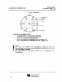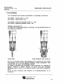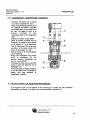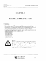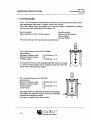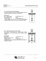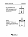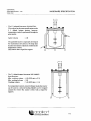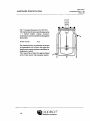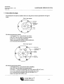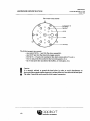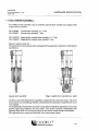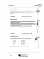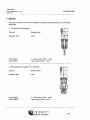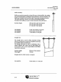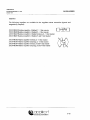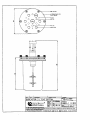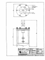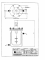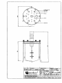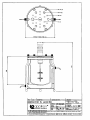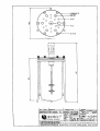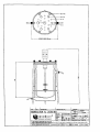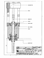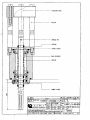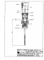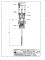
1
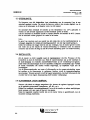
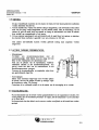
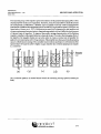
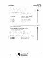
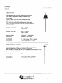
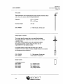
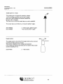
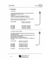
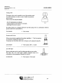
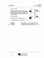
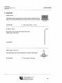
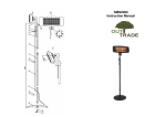
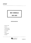
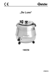
GEBRUIKSAANWIJZING
Autoclaveerbare Bioreactor 2 - 7 1
Oktober 1994
AUTOCLAVEERBARE
BIOREACTOR
2 - 7 LITER
GEBRUIKSAANWIJZING
DEPENDABLE INSTRUMENTS
V3UBNL0061
GEBRUIKSAANW1JZING
INHOUD
Autoclaveerbare Bioreactor 2 - 7 liter
Oktober 1994
INHOUDSOPGAVE
Hoofdsruk
Omschrijvmg
Pagina
1
1.1
1.2
1.3
1.4
Hardware specificatie
Algemeen
De reactoren
De deksels
De roerder
1-1
1-1
1-2
1-7
1-9
Roeren en beluchten
2-1
3
3.1
3.2
3.3
3.4
3.5
3.6
3.7
3.8
Gebruik
Algemeen
Klaarmaken voor sterilisatie
Sterilisatie
Installatie
Klaarmaken voor gebruik
Enting
Acties tijdens fermentatie
Pasteurisatie
3-1
3-1
3-1
3-2
3-2
3-2
3-3
3-3
3-3
4
4.1
4.2
4.3
Onderhoud
De reactor
De roerder
Hulpstukken en reserveonderdelen
4-1
4-1
4-2
4-3
DEPENDABLE INSTRUMENTS
GEBRUIKSAANW1JZING
Autoclaveerbare Bioreactor 2 - 7 liter
Oktober 1994
HARDWARE SPECIFICATIE
HOOFDSTUK 1
HARDWARE SPECIFICATIE
1.1 ALGEMEEN:
De geroerde-tank reactor is het in de praktijk van de biotechnologie meest toegepaste type
bioreactor.
De 2 - 7 liter autoclaveerbare bioreactoren van Applikon brengen verschillende voordelen
met zich mee; door modulair en flexibel ontwerp wordt de beschikbare ruimte optimaal
benut en is de reactor zeer praktisch in het gebruik.
In combinatie met de roersystemen, motoren, roervinnen en andere hulpstukken van
Applikon kan elke gevraagde configuratie snel worden opgebouwd, bijvoorbeeld voor
toepassingen als:
- medium optimalisatie,
- controle van cellijnen,
- produkt optimalisatie,
- studies ten aanzien van schaalvergrotingAverkleining,
- reactor optimalisatie,
- continue culturen,
- perfusie systemen, etc.
Gevaar:
Glas is een materiaal dat snel beschadigd kan worden
(krasjes op het oppervlak). Daardoor vermindert de
materiaalsterkte. De procesdruk dient om deze reden
beneden de 50 kPa (0.5 bar, 7 psig) gehouden te worden.
Reduceer de inlaatdruk van de gassen tot dit niveau of
gebruik een juist ingestelde drukveiligheid!
DEPENDABLE INSTRUMENTS
1-1
GEBRUIKSAANW1JZING
HARDWARE SPECIFICATIE
Autoclaveerbare Bioreactor 2 - 7 liter
OKtober 1994
1.2 DE REACTOREN:
De 2 - 7 liter bioreactoren zijn ideale gereedschappen voor onderzoekers die zich bezig
houden met fermentatiestudies en voor die toepassingen waar kleine of middelmatige
reactorvolumes worden gebruikt.
Vanwege het modulair ontwerp kunnen de reactoren ingezet worden bij een scala van
toepassingen met inbegrip van microbiologische- en gistfermentaties, dierlijke en
plantaardige celkweek, etc.
Reactormateriaal:
Andere materialen in kontakt met het medium:
borosilicaat glas.
roestvast staal (deksel),
silicone rubber,
viton en EPDM.
De reactor-typen en bijbehorende specificaties staan hieronder weergegeven.
De 2 1 bioreactor met schaalvormige bodem Z611020002:
Specificaties:
Maximum werkvolume
2.21 (H/D verhouding = 2.3)
Minimum werkvolume
0.51
Werkvolume
1.71 (H/D verhouding = 1.9)
Een warmtewisselaar binnen de reactor of een siliconen
verwarmingsmantel om de reactor heen kunnen worden gebruikt
voor de temperatuurregeling. De reactor wordt geleverd met
standaard.
- De 2 1 bioreactor met mantel Z61104CT04:
Specificaties:
Maximum werkvolume
2.21 (H/D verh. = 2.3)
Minimum werkvolume
0.51
Werkvolume
1.71 (H/D verh. = 1.9)
Mantelvolume
1.31
Deze reactor is speciaal ontwikkeld voor de dierlijke
celkweek; het grote verwarmingsoppervlak en de
warmtecapaciteit van water verzekert een optimale
temperatuurregeling.
De reactor wordt geleverd met standaard.
DEPENDABLE INSTRUMENTS
1-2
U
GEBRUIKSAANW1JZING
HARDWARE SPECIFICATIE
Autoclaveerbare Bioreactor 2 - 7 liter
Oktober 1994
De 3 1 bioreactor met platte bodem Z611000004:
Deze reactor wordt vooral gebruikt voor bacteriele fermentaties
met micro-organismen die niet gevoelig zijn voor afschuifkrachten.
Specificaties:
Maximum werkvolume
Minimum werkvolume
Werkvolume
R hi PI
LLy.il
3.21 (H/D verhouding = 1.8)
0.441
2.61 (H/D verhouding = 1.5)
Een warmtewisselaar binnen de reactor of een siliconen
verwarmingsmantel om de reactor heen kunnen worden gebruikt
voor de temperatuurregeling.
De 3 1 bioreactor met schaalvormige bodem Z61101C006:
Deze reactor wordt normaal gebruikt voor het kweken van voor
afschuifkrachten gevoelige cellen/organismen. De schaalvormige
bodem zorgt voor optimale roer-eigenschappen.
Specificaties:
Totaalvolume
Minimum werkvolume
Werkvolume
EJ |4 H
LLiiij
3.21 (H/D verhouding = 1.9)
0.47 1
2.71 (H/D verhouding = 1.5)
Een warmtewisselaar binnen de reactor of een siliconen
verwarmingsmantel om de reactor heen kunnen worden gebruikt
voor de temperatuurregeling.
De reactor wordt geleverd met standaard.
DEPENDABLE INSTRUMENTS
1-3
GEBRUIKSAANW1JZING
HARDWARE SPECIFICATE
Autoclaveerbare Bioreactor 2 - 7 liter
Oktober 1994
H 11 H
IIR l I
- De 3 1 bioreactor met mantel Z61103CT04:
Deze reactor heeft dezelfde specificaties als de 3 1
reactor met schaalvormige bodem; echter, de
temperatuurregeling wordt nu tot stand gebracht
door middel van een watermantel, hetgeen een meer
nauwkeurige regeling oplevert. De mantel kan
worden gebruikt voor zowel verwarmen als koelen.
Mantel volume
De 5 1 bioreactor met
Z611000005:
Specificaties:
Maximum werkvolume
Minimum eorkvolume
Werkvolume
1.31
schaalvormige
bodem
: 4.81 (H/D verh. = 1.6)
:21
: 3.41 (H/D verh. = 1.1)
Een warmtewisselaar binnen de reactor of een siliconen
verwarmingsmantel om de reactor heen kunnen worden
gebruikt voor de temperatuurregeling.
De reactor wordt geleverd met standaard.
apDiiKorf
1-4
DEPENDABLE INSTRUMENTS
I*
1
H.
"
"
GEBRUIKSAANW1JZING
Autoclaveerbare Bioreactor 2 - 7 liter
Oktober 1994
HARDWARE SPECIFICATIE
De 5 1 bioreactor met mantel
Z61104CT05:
Deze reactor heeft dezelfde specificaties
als de 5 1 reactor met schaalvormige
bodem; echter, de temperatuurregeling
wordt nu tot stand gebracht door middel
van een watermantel, hetgeen een meer
nauwkeurige regeling oplevert. Hierdoor is
deze geschikt voor dierlijke celkweek.
De mantel kan worden gebruikt voor
zowel verwarmen als koelen.
Mantelvolume
: 2.81
ti
De reactor wordt geleverd met standaard.
De 7 1 bioreactor
Z611000007:
Specificaties:
Maximum werkvolume
Minimum werkvolume
Werkvolume
met
schaalvormige
bodem
6.91 (H/D verh. = 2.2)
2.01
5.41 (H/D verh. = 1.8)
Een warmtewisselaar binnen de reactor of een siliconen
verwarmingsmantel om de reactor heen kunnen worden
gebruikt voor de temperatuurregeling.
De reactor wordt geleverd met standaard.
DEPENDABLE INSTRUMENTS
1-5
GEBRUIKSAANW1JZING
HARDWARE SPECIFICATE
Autoclaveerbare Bioreactor 2 - 7 liter
Oktober 1994
De 7 1 bioreactor met mantel
Z61103CT07:
Deze reactor heeft dezelfde specificaties
als de 7 1 reactor met schaalvormige
bodem; echter, de temperatuurregeling
wordt nu tot stand gebracht door middel
van een watermantel, hetgeen een meer
nauwkeurige regeling oplevert. Hierdoor is
deze geschikt voor dierlijke celkweek.
De mantel kan worden gebruikt voor
zowel verwarmen als koelen.
Mantelvolume
: 4.21
De reactor wordt geleverd met standaard.
DEPENDABLE INSTRUMENTS
1-6
GEBRUIKSAANW1JZING
Autoclaveerbare Bioreactor 2 - 7 liter
Oktober 1994
HARDWARE SPECIFICATE
1.3 DE DEKSELS:
De reactordeksels zijn gemaakt van roestvast staal 316. De indeling van de gaten in de
deksels is weergegeven in de onderstaande tekeningen.
De 2 liter reactor:
MILL NUT (6x)
M18x1.5 ( 5 x )
CONTACT HOLE FOR
LEVEL CONTROL.
Dit deksel bevat de volgende poorten:
- een centrale M 30 x 1 poort (voor de bovenroerder),
- een G3/4" poort (voor de opgelost zuurstof sensor),
- vijf M 18 x 1.5 poorten (voor hulpstukken),
- drie 6 mm poorten (voor keerschotten of andere hulpstukken),
- zes 10 mm poorten (voor hulpstukken).
De 3 liter reactor:
MILL NUT (6x)
02 CONTACT HOLE FOR
LEVEL CONTROL.
012 (2x)
M18x1.5 (5x)
Dit deksel bevat de volgende poorten:
- een centrale M 30 x 1 poort (voor de bovenroerder),
- een G3/4" poort (voor de opgelost zuurstof sensor),
- vijf M 18 x 1.5 poorten (voor hulpstukken),
- drie 6 mm poorten (voor keerschotten of andere hulpstukken),
- zes 10 mm poorten (voor hulpstukken).
- twee 12 mm poorten (voor hulpstukken zoals een oogstpijp, etc.),
toappiikorf
^ ^ 1 ^ ^
DEPENDABLE INSTRUMENTS
1-7
GEBRUIKSAANW1JZING
HARDWARE SPECIFICATE
Autoclaveerbare Bioreactor 2 - 7 liter
Oktober 1994
De 5 en 7 liter reactor:
«2 CONTACT HOLE FOR
LEVEL CONTROL.
MILL NUT (6x)
Dit deksel bevat de volgende poorten:
- een centrale M 30 x 1 poort (voor de bovenroerder),
- een G3/4" poort (voor de opgelost zuurstof sensor),
- vijf M 18 x 1.5 poorten (voor hulpstukken),
- tien 10 mm poorten (voor hulpstukken, zoals keerschotten, etc.),
- twee 12 mm poorten (voor hulpstukken zoals een oogstpijp, etc.).
I
Let op:
Het is zeer aan te bevelen om het reactordeksel te aarden om ruis op de
electrodesignalen te voorkomen (statische electriciteit); gebruik hiervoor een van de
twee 2 mm gaatjes in het deksel.
Het andere gaatje kan dan gebruikt worden voor de aansluiting van de
niveauregeling.
tgapoiikorf
^
1-8
^
^
DEPENDABLE INSTRUMENTS
GEBRUIKSMNWIJZING
Autoclaveerbare Bioreactor 2 - 7 liter
Oktober 1994
HARDWARE SPECIFICATIE
1.4 DE ROERDER:
Twee verschillende typen roerders zijn beschikbaar voor toepassing in bioreactoren:
Z81315R003: Lipseal roerder 2, 3, 5 liter
Z81315R007: Lipseal roerder 7 liter
Z81315MG03: Magnetisch gekoppelde roerder 2, 3, 5 liter
Z81315MG07: Magnetisch gekoppelde roerder 7 liter
Materiaal: roestvast staal 316.
De roerders zijn volledig autoclaveerbaar en ontworpen voor lange gebruiksperioden met
een minimum aan onderhoud.
Lipseal roerder
Magn. gekoppelde roeder (zonder as)
De roeras van de lipseal roerder is direct gekoppeld aan de roermotor die op de roerder
wordt geplaatst. Dit is de meest gebruikte benadering, waarbij infectiegevaar wordt
voorkomen door een viertal viton afdichtingen (lipseals).
De magnetisch geloppelde roeras daarentegen is special ontworpen voor toepassing bij
genetisch onderzoek en dierlijke celkweek. Dit ontwerp bevat geen bewegende
afdichtingen tussen de reactor en de omgeving waardoor veilig gebruik gegarandeerd
wordt.
De toe te passen roermotoren staan beschreven in de gebruiksaanwijzing van de
roermotoren.
DEPENDABLE INSTRUMENTS
1-9
GEBRUIKSAANW1JZING
Autoclaveerbare Bioreactor 2 - 7 liter
ROEREN EN BELUCHTEN
Oktober 1994
HOOFDSTUK 2
ROEREN EN BELUCHTEN
Om te komen tot een optimaal gedrag van een willekeurig biologisch systeem, is het
noodzakelijk de omgeving van het micro-organisme in optimale conditie te houden.
Naast temperatuur en mediumsamenstelling, zijn de twee meest belangrijke faktoren die
de omgevingsconditie beinvloeden de mate van roeren en beluchten.
In de Engelse versie van deze gebruiksaanwijzing wordt uitgebreid aandacht besteed aan
de theoretische en praktische kanten van deze materie; tevens kunt u in getalvorm
gegevens vinden ten aanzien van mengtijden en snelheid van zuurstofoverdracht voor de
hele range van de Applikon autoclaveerbare reactoren.
DEPENDABLE INSTRUMENTS
2-1
GEBRU1KSAANW1JZING
Autoclaveerbare Bioreactor 2 - 7 liter
GEBRUIK
Oktober 1994
HOOFDSTUK 3
GEBRUIK
3.1 ALGEMEEN:
Controleer bij het uitpakken van de reactor of er geen transportschade aan het systeem is
aangericht en of het kompleet (in overeenstemming met de order) is afgeleverd.
Reinig alle delen met 70% ethanol. Wees voorzichtig bij het in elkaar zetten van de reactor
en bijgeleverde hulpstukken om zodoende schade aan de poorten met schroefdraad te
voorkomen; monteer de hulpstukken altijd vertikaal in het deksel en draai de
bevestigingsringen slechts handvast aan.
Let op dat de O-ring aanwezig is tussen het hulpstuk en het reactordeksel om zodoende
steriliteit te garanderen.
3.2 KLAARMAKEN VOOR STERIHSATIE:
Vul het vat met kweekmedium; overschreid hiermee niet het maximum volume dat in
hoofdstuk 1 wordt gegeven (hardware specificatie). Reserveer voldoende volume voor
toevoegingen na sterilisatie (zoals inoculatie vloeistof, apart gesteriliseerde nutrienten, en
dergelijke).
Draai de zes kartelmoeren op het deksel kruiselings handvast aan.
Controleer of de electroden goed functioneren (vul het electroliet van de pH-electrode bij).
Steek de "niveau-sensor" zo ver mogelijk in de reactor en zet deze vast (na sterilisatie kan
deze op het juiste niveau naar boven toe worden bijgesteld).
Controleer de bevestiging van alle hulpstukken. Sluit de slangen voor toevoegingen aan,
zoals vloeistoffen, lucht-in en lucht-uit; gebruik hiervoor siliconenslang of ander
steriliseerbaar materiaal.
Gebruik voor dit doel geschikte luchtfilters voor in- en uitgaande lucht. Sluit de slang
tussen deksel en het luchtinlaatfilter af met een slangenklem om te voorkomen dat het
filter van binnen nat wordt tijdens de sterilisatie.
Sluit alle andere aansluitingen af met uitzondering van de luchtuitlaat; via het filter kan
er zo drukevenwicht tot stand komen tijdens sterilisatie. Vul alle open slanguiteinden met
een wattenprop en bedek deze met aluminiumfolie tegen het nat worden.
De warmtewisselaar dient leeg te zijn.
DEPENDABLE INSTRUMENTS
3-1
GEBUIKSAANWIJZING
GEBRUIK
Autoclaveerbare Bioreactor 2 - 7 liter
Oktober 1994
3.3 STERILISATIE:
De bioreactor met alle hulpstukken (met uitzondering van de roermotor) kan in een
autoclaaf geplaatst worden. De ruimte die hiervoor nodig is kan worden afgeleid van de
maten op de tekeningen in de Engelse versie van dit manual.
De autoclaaf dient minimaal 20 minuten op een temperatuur van 121°C gehouden te
worden om alle levende organismen en hitte-resistente sporen te doden.
Laat de autoclaaf na sterilisatie zonder te openen afkoelen tot beneden de 90°C. Daarna
kan de autoclaaf worden geopend om verder af te koelen.
N.B.:
In geval van reactoren met een mantel kan het nodig zijn om het sterilisatieinterval te
verlengen aangezien de warmte-uitwisselingscapaciteit van een lege mantel gering is.
Indien het medium een langer interval niet kan verdragen, kan de mantel gevuld worden
met water om op die manier de warmte-uitwisseling te verbeteren (sluit de onderste
connector aan en klem de slang af, laat de bovenste aansluiting open voor drukevenwicht).
3.4 INSTALLATIE:
Zet de reactor zo dicht mogelijk naast de regelapparatuur (de Bio Processor of Bio
Controller) en sluit de electroden aan. Sluit de warmtewisselaar aan op het waterbad en
de lucht-inlaatpijp en eventuele zuurstof7stikstof-inlaat op de voorziening-voor-gassen;
maak verder alle aansluitingen die in uw specifieke configuratie noodzakelijk zijn. Verbind
de sterile vloeistoffen die moeten worden toegevoegd, op aseptische wijze met de
invoerpijpjes.
Vul de thermometerhouder met water of siliconenolie om de warmte-uitwisseling tussen
het medium en de thermometer te verbeteren; hierdoor wordt de temperatuurregeling
nauwkeuriger. Wanneer gewerkt wordt bij hogere temperaturen, dan heeft siliconenolie het
voordeel dat het een lagere dampspanning heeft (minder verdamping).
3.5 KLAARMAKEN VOOR GEBRUIK:
Wanneer alle kabels en slangen aangesloten zijn, kunnen de regelaars ingeregeld worden
op de optimale proceswaarde (temperatuur, pH, dO2, etc.).
Schakel het waterbad (verwarmingselement) in en zet de roerder en andere aandrijvingen
(zoals pompen e.d.) aan; open de toevoer van gassen.
Nadat de ingestelde waarden bereikt zijn en de reactor hierop is gestabiliseerd, kan de
inoculatie (enting) plaatvinden.
DEPENDABLE INSTRUMENTS
3-2
GEBRUIKSAANWIJZING
GEBRUIK
Autoclaveerbare Bioreactor 2 - 7 liter
Oktober 1994
3.6 ENTING:
Er zijn verschillende manieren om een reactor te enten; de twee meest gebruikte methoden
worden hieronder beschreven:
1. Vul een steriele fles, waarop een steriele slang is aangesloten, met entvloeistof. Het andere
eind van de slang wordt aangesloten op een steriele naald. Sluit de beluchting van de
reactor af, prik de naald door het septum en breng de entvloeistof over naar de reactor
door middel van zwaartekracht of een pomp.
2. Vul een steriele injectiespuit met entvloeistof; prik de naald door het septum en injecteer
de vloeistof (deze methode is geschikt voor ent-volumina tot 100 ml).
Ook andere ent-methoden kunnen worden gebruikt zolang deze aseptisch worden
uitgevoerd.
3.7 ACTIES TIJDENS FERMENTATIE:
- Monstername:
Verbindt een monsternamesysteem
met
de
monsternamepijp. Sluit hierop (via een slang met een
filter of een wattenprop) een injectiespuit aan.
Trek aan de plunjer van de injectiespuit, waardoor
onderdruk ontstaat in het monsternamesysteem. Als
gevolg wordt een deel van de reactorinhoud in het
monsternamesysteem gezogen.
Vervang de monsternamefles op aseptische wijze door
een gesteriliseerde lege fles.
- Toevoegingen:
Ill
Indien extra substraat toegevoegd moet worden tijdens
de kweek, dan kan dit gedaan worden op analoge wijze
als beschreven onder 3.6 (Enting).
Controleer of er voldoende ruimte is in de reactor om de toevoeging uit te voeren.
3.8 PASTEURISATIE:
Na de fermentatie kan de kweek worden gepasteuriseerd om de organismen te doden. Dit
wordt gedaan door de sterilisatie-procedure te volgen; stel de temperatuur van de autoclaaf
in op circa 80°C.
Na pasteurisatie kan het deksel van de reactor worden verwijderd en de kweek kan worden
geoogst.
DEPENDABLE INSTRUMENTS
3-3
GEBRU1KSAANW1JZING
Autoclaveerbare Bioreactor 2 - 7 liter
ONDERHOUD
Oktober 1994
HOOFDSTUK 4
ONDERHOUD
4.1 DE REACTOR EN HET DEKSEL:
Na beeindiging van het fermentatieproces dienen de glazen en roestvast stalen onderdelen
grondig te worden gereinigd. Gebruik hiervoor heet water, 70% ethanol of andere
geschikte reinigingsmiddelen. Gebruik nooit schuurmiddelen om de metalen onderdelen
te reinigen.
Laat de onderdelen drogen en zet de reactor weer in elkaar. Let op: vergeet geen O-ringen
en zorg ervoor dat ze niet beschadigd worden, aangezien dit tot infectie kan leiden tijdens
de volgende kweek.
Wanneer de reactor regelmatig gebruikt wordt, is het aan te raden om de O-ringen van de
hulpstukken twee maal per jaar te vervangen.
N.B.:
Zorg dat de pH-electrode grondig wordt schoongemaakt voordat hij wordt opgeborgen;
volg de voorschriften in de gebruiksaanwijzing van de electrode.
DEPENDABLE INSTRUMENTS
4-1
GEBRUIKSAANW1JZING
ONDERHOUD
Autoclaveerbare Bioreactor 2 - 7 liter
Oktober 1994
4.2 DE ROERDER:
De roerder dient twee maal per jaar uit elkaar genomen en onderhouden te worden.
Instrukties hiervoor staan hieronder vermeld.
4.2.1 LIPSEAL ROERDER:
- Verwijder het deksel van de reactor
en verwijder de roervinnen van de
roeras. Schroef de roerder uit het
deksel.
- Verwijder de koppelingsring (A) door
de vier schroeven te verwijderen.
- Schroef de pennen (B) los waarop de
koppelingsring was bevestigd en
verwijder de "spring pin" (C) en de
bovenste lipseal (D).
Verwijder de bovenplaat (E).
- Verwijder de onderplaat (H) door de
drie kleine schroeven los te
schroeven en lipseal te verwijderen.
- Verwijder borgveer (G) die kogellager (F) op zijn plaats houdt.
- Zet de roerder op zijn kop en duw de
as langzaam uit het kogellagerhuis.
Dit gaat het meest gemakkelijk door
de roeras (op zijn kop) op een tafel te
zetten en het kogellagerhuis naar
beneden te drukken.
- Reinig alle onderdelen en smeer de
kogellager met hiervoor speciaal
beschikbaar vet (art. no.
V3LA120031).
Vervang zonodig O-ringen en/of
lipseals en zet de roerder weer
voorzichtig in elkaar; volg deze
instructie in omgekeerde volgorde.
B
DEPENDABLE INSTRUMENTS
4-2
GEBRUIKSAANWIJZING
ONDERHOUD
Autoclaveerbare Bioreactor 2 - 7 liter
Oktober 1994
4.2.2 MAGNETISCH GEKOPPELDE ROERDER:
Verwijder het deksel van de reactor
en zet deze ondersteboven neer.
Draai de ontmantelingsschroef (A) zo
ver mogelijk naar binnen. Verwijder
het onderste deel van de roerder door
de rotor (B) tegen de klok in te
draaien. Verwijder
de rotor
voorzichtig; denk om het magnetisch
veld!
Schroef de roerder uit het deksel.
Neem de roerder uit elkaar door de
bovenste vier schroeven los te maken
en de pennen (C) los te schroeven.
Trek de "spring pin" (D) uit de as en
verwijder de bovenste lipseal (E).
Neem de bovenplaat (F) weg.
Trek de roeras en de binnenmagneet
uit de behuizing.
Reinig alle onderdelen met celstof,
smeer de kogellagers (G) met
speciaal hiervoor beschikbaar vet
(art. no. V3LA120031).
Verwijder de roeras van de rotor (B);
reinig en smeer het oppervlak van de
kogellager (G).
Vervang zonodig O-ringen of lipseals
en zet de roerder weer voorzichtig in
elkaar; volg deze instructie in
omgekeerde volgorde.
4.3 HULPSTUKKEN EN RESERVEONDERDELEN:
In de Engelse versie van dit manual is een opsomming te vinden van alle toepasbare
hulpstukken (hoofdstuk 5) en lijsten met reserveonderdelen (hoofdstuk 6).
DEPENDABLE INSTRUMENTS
4-3
USER MANUAL
Autoclavable Bioreactor 2 - 7 1
October 1994
AUTOCLAVABLE
BIOREACTOR
2 - 7 LITER
USER MANUAL
appiikorf
DEPENDABLE INSTRUMENTS
V3UBCE0061
tDappikorf
^ ^ ^ ^ DEPENDABLE INSTRUMENTS
USER M A N U A L
CONTENTS
Autoclavable Bioreactor 2 - 7 liter
October 1994
TABLE OF CONTENTS
Chapter
Description
Page
1
1.1
1.2
1.3
1.4
Hardware specification
General
The reactors
The head plates
The stirrer assemblies
1-1
1-1
1-2
1-7
1-9
2
2.1
2.2
2.3
Mixing and aeration
Mixing
Aeration
Literature
2-1
2-1
2-6
2-9
3
3.1
3.2
3.3
3.4
3.5
3.6
3.7
3.8
Operation
General
Preparing for sterilization
Sterilization
Installation
Preparing for operation
Inoculation
Actions during fermentation
Pasteurization
3-1
3-1
3-1
3-2
3-2
3-2
3-3
3-3
3-3
4
4.1
4.2
Maintenance
The reactor
The stirrer assembly
4-1
4-1
4-2
5
5.1
5.2
5.3
5.4
5.5
5.6
5.7
Auxiliaries
Sampling
Aeration
Addition
Mixing
Heat exchangers
Sensor holders
Blind stoppers
5-1
5-1
5-6
5-9
5-11
5-14
5-15
5-16
Drawings
6-1
applikorf
DEPENDABLE INSTRUMENTS
toapplikorf
^ ^ ^ ^ DEPENDABLE INSTRUMENTS
U S E R MANUAL
HARDWARE SPECIFICATION
Autoclavable Bioreactor 2 - 7 liter
October 1994
CHAPTER 1
HARDWARE SPECIFICATION
1.1 GENERAL:
The stirred tank reactors (STR) are the most applied reactor types in biotechnology.
The Applikon 2 - 7 liter autoclavable bioreactors offer several advantages; its modular and
flexible design requires minimum bench space and is very practical in operation.
In combination with Applikons stirrer assemblies, motors, impellers and auxiliaries, you can
configure the reactor for a variety of applications, like:
- medium optimization,
- screening of strains,
- product optimization,
- scale up/down studies,
- reactor optimization,
- continuous cultures,
- perfusion systems, etc.
Danger:
Glass is a material that may be damaged easily (scratches
on the surface)! As a result, its strength is reduced.
Therefore do not apply a process pressure that exceeds 50
kPa (0.5 bar, 7 psig).
Reduce the pressure of the inlet gasses to this extend or
apply a pressure relief that is properly adjusted.
appiikorf
DEPENDABLE INSTRUMENTS
1-1
U S E R MANUAL
HARDWARE SPECIFICATION
Autoclavable Bioreactor 2 - 7 liter
October 1994
1.2 THE REACTORS:
The 2 - 7 liter bioreactors are ideals tool for researchers who start fermentation studies and for
those applications where small or medium volumes are required.
Due to the modular design, the reactors can be used for a variety of applications, including
microbial and yeast fermentations, cell cultures, etc.
Reactor material:
Other materials in contact with the medium:
borosilicate glass,
stainless steel (head plate),
silicone rubber,
viton and EPDM.
The reactor types and their specifications are listed below.
The 2 1 dished bottom bioreactor Z611020002:
Specifications:
Maximum working volume
: 2.21 (H/D ratio = 2.3)
Minimum working volume
: 0.51
Working volume
: 1.71 (H/D ratio = 1.9)
\
For temperature control, a heat exchanger inside the reactor can be used
or a silicone heating blanket can be wrapped around the vessel. The
reactor comes with a tripod for support.
The 2 1 jacketed bioreactor Z61104CT04:
Specifications:
Maximum working volume
: 2.21 (H/D ratio = 2.3)
Minimum working volume
: 0.51
Working volume
: 1.71 (H/D ratio =1.9)
Jacket volume
: 1.31
The jacketed reactor is especially developed for mammalian
cell cultures; the large heat transfer area ensures optimum
conditions for temperature control.
The tripod is supplied with extension shafts.
1-2
IQapplikorf
^ ^ ^ ^
DEPENDABLE INSTRUMENTS
U
B
USER MANUAL
HARDWARE SPECIFICATION
Autoclavable Bioreactor 2 - 7 liter
October 1994
The 3 1 flat bottom bioreactor Z611000004:
This reactor is generally used for bacterial fermentations with micro
organisms that are not very sensitive to shear forces.
NLIN
Specifications:
Max. working volume
: 3.21 (H/D ratio =1.8)
Min. working volume
: 0.441
Working volume
: 2.61 (H/D ratio = 1.5)
A heat exchanger, inside the vessel, or a silicone heating blanket,
wrapped around the vessel, can be used for temperature control.
The 3 1 dished bottom bioreactor Z61101C006:
This reactor is mostly used for culturing shear sensitive
cells/organisms. The dished bottom ensures optimum mixing
properties.
Specifications:
Total volume
3.21 (H/D ratio = 1.9)
Minimum working volume
0.47 ml
Working volume
2.71 (H/D ratio = 1.5)
Temperature control can be obtained in the same way as with the 3 1
flat bottom bioreactor.
appiikort
DEPENDABLE INSTRUMENTS
1-3
USER M A N U A L
HARDWARE SPECIFICATION
Autoclavable Bioreactor 2 - 7 liter
October 1994
R fcj
The 3 1 jacketed bioreactor Z61103CT04:
This reactor has the same specifications as the 3 1
dished bottom reactor; however, temperature control is
performed through the glass jacket. In this way, the
temperature can be controlled more accurately; the
jacket can both be used for heating and cooling.
I
!!
Internal jacket volume : 1.31
"TT
The 5 1 dished bottom bioreactor Z611000005:
Specifications:
Max. working volume : 4.81 (H/D ratio = 1.6)
Min. working volume : 21
Working volume
: 3.41 (H/D ratio =1.1)
For temperature control, a heat exchanger inside the reactor
can be used or a silicone heating blanket can be wrapped
around the vessel. The reactor comes with a tripod for
support.
1-4
Igappiikon
^ ^ ^ ^
DEPENDABLE INSTRUMENTS
USER M A N U A L
HARDWARE SPECIFICATION
Autoclavable Bioreactor 2 - 7 liter
October 1994
F1
The 5 1 jacketed bioreactor Z61104CT05:
This reactor has the same specifications as the
5 1 dished bottom reactor; however,
temperature control is performed through the
glass jacket.
Jacket volume
JJL
2.81
The jacketed reactor is especially developed
for mammalian cell cultures; the large heat
transfer area ensures optimum conditions for
temperature control.
This reactor has a tripod for support.
^
,
i
L
ti
JJL
JUL
The 7 1 dished bottom bioreactor Z611000007:
Specifications:
Max. working volume : 6.91 (H/D ratio = 2.2)
Min. working volume : 2.01
Working volume
: 5.41 (H/D ratio =1.8)
For temperature control, a heat exchanger inside the reactor
can be used or a silicone heating blanket can be wrapped
around the vessel. The reactor comes with a tripod for
support.
appiikorf
DEPENDABLE INSTRUMENTS
1-5
USER M A N U A L
HARDWARE SPECIFICATION
Autoclavable Bioreactor 2 - 7 liter
October 1994
NMH
The 7 1 jacketed bioreactor Z61103CT07:
This reactor has the same specifications as the
7 1 dished bottom reactor; however,
temperature control is performed through the
glass jacket.
Jacket volume
4.21
The jacketed reactor is especially developed
for mammalian cell cultures; the large heat
transfer area ensures optimum conditions for
temperature control.
This reactor has a tripod for support (tripod
of the 5 liter reactor with extension shafts).
1-6
Igapplikorf
^ ^ ^ ^
DEPENDABLE INSTRUMENTS
USER M A N U A L
HARDWARE SPECIFICATION
Autoclavable Bioreactor 2 - 7 liter
October 1994
1.3 THE HEAD PLATES:
The head plates are made of stainless steel 316. The port lay-outs are presented in the figures
below:
The 2 liter reactor:
MILL NUT ( 6 K )
M18xl.5 (5x)
CONTACT HOLE FOR
LEVEL CONTROL
The following ports are present:
- one central M 30 x 1 port (for the top stirrer),
- one G3/4" port (for dissolved oxygen sensor),
- five M 18 x 1.5 ports (for auxiliaries),
- three 6 mm ports (for baffles or other auxiliaries),
- six 10 mm ports (for auxiliaries).
The 3 liter reactor:
MILL NUT (6x)
02 CONTACT HOLE FOR
LEVEL CONTROL.
«6 (3x)
(6x)
012 (2x)
M18x1.5 (5x)
The following ports are present:
- one central M30 x 1 port (for the stirrer assembly),
- one G3/4" port (for dissolved oxygen sensor),
- five Ml 8 x 1.5 ports (for auxiliaries like other sensors (pH, mV), etc.),
- two 12 mm ports (for auxiliaries like harvesting pipes, etc.),
- six 10 mm ports (for auxiliaries like air inlet pipes, etc.),
- three 6 mm ports (for baffles, etc.).
applikorf
DEPENDABLE INSTRUMENTS
1-7
USER MANUAL
HARDWARE SPECIFICATION
Autoclavable Bioreactor 2 - 7 liter
October 1994
The 5 and 7 liter reactor:
• 2 CONTACT HOLE FOR
LEVEL CONTROL.
MILL NUT (6x)
The following ports are present:
- one central M 30 x 1 port (for the stirrer assembly),
- one G3/4" port (for the dissolved oxygen sensor),
- five M 18 x 1.5 ports (for auxiliaries like other sensors (pH, mV), etc.),
- two 12 mm ports (for auxiliaries like harvesting pipes, etc.),
- ten 10 mm ports (for auxiliaries like baffles, air inlet pipes, etc).
I
1-8
Caution:
It is strongly advised to ground the head plate in order to avoid disturbances on
electrode/sensor signals (static electricity); use one of the two 2 mm holes in the head plate.
The other 2 mm hole can be used for level control connection.
Igappiikorf
^ ^ ^ ^
DEPENDABLE INSTRUMENTS
U S E R MANUAL
HARDWARE SPECIFICATION
Autoctavable Bioreactor 2 - 7 liter
October 1994
1.4 THE STIRRER ASSEMBLY:
Two different stirrer assembly types are available: a lipseal stirrer assembly and a magnetically
coupled stirrer assembly.
Z81315R003:
Z81315R007:
Lipseal stirrer assembly 2,3,5 liter
Lipseal stirrer assembly 7 liter
Z81315MG03: Magnetically coupled stirrer assembly 2, 3, 5 liter
Z81315MG07: Magnetically coupled stirrer assembly 7 liter
Material: stainless steel 316.
The assemblies are autoclavable and are designed for long periods of operation with minimum
maintenance.
Lipseal stirrer assembly
Magn. coupled stirrer assembly (ex. shaft)
The stirrer shaft of the lipseal stirrer assembly is coupled directly to the stirrer motor. This is the
most common way of coupling, whereby contamination-free operation is ensured by the use of
viton lipseals.
The magnetically coupled stirrer assembly is especially developed for applications concerning
genetic engineering organisms and cell culture. This ensures absolute contamination-free
operation since there is no moving seal between the reactor content and the environment.
The applicable stirrer motors are described in the stirrer motor manual.
appiikorf
DEPENDABLE INSTRUMENTS
1-9
USER MANUAL
HARDWARE SPECIFICATION
Autociavable Bioreactor2-7 liter
October 1994
1-10
Igappiikori
^ ^ ^ ^ DEPENDABLE INSTRUMENTS
USER MANUAL
Autoclavable Bioreactor2-7 liter
MIXING AND AERATION
October 1994
CHAPTER 2
MIXING AND AERATION
For an optimum performance of any biological system, it is necessary to keep the environment
of the micro-organisms at optimal conditions. Apart from temperature and medium composition,
the two most important factors that effect this environment are the degree of mixing and
aeration.
2.1 MIXING:
The aim of mixing is to obtain uniform conditions in the working volume of the bioreactor, in
order to obtain an optimal mass transfer, to avoid gradients of any of the medium components,
and to keep the microcarriers or cells in suspension. In a normally used stirred tank reactor,
mixing is accomplished by the impeller. The resulting flow pattern is a function of the impeller
configuration, agitation speed, the geometry of the system and gas inflow rate employed.
One aspect of mixing is preventing the cells or microcarriers to settle. In order to achieve this,
the fluid velocity must at least be equal to the settling velocity of the particles (vsett), which can
be calculated according to Stokes1 law (Cherry and Papoutsakis, 1986):
v
sett= dp2'(Ps" Pf)'g/(18-r|)
where: dp
ps
pf
g
r\
= particle diameter (m),
= particle density (kg m"3),
= medium density (kg m"3),
= gravitational constant (m s"2)
= medium viscosity (N m s"1).
Stokes1 law only holds for particles whose Reynolds numbers are smaller than 1 (which holds
for all normally used biological systems). As the biomass should be homogeneously distributed
throughout the reactor, not only must the particles be lifted from the bottom of the vessel but
they must also be transported through the whole volume of the reactor.
appiikorf
DEPENDABLE INSTRUMENTS
2-1
USER MANUAL
MIXING A N D A E R A T I O N
Autoclavable Bioreactor2-7 liter
October 1994
Generally, the minimum required stirring speed to achieve homogeneous suspension, Nta, is
much greater than that to lift the particles from the bottom of the reactor. Buurman et al. (1986)
also derived a simple Froude relationship to define homogeneity in a stirred tankreactor (STR),
based on the assumption of fluctuating velocity being proportional to the circulation velocity:
pf-Nhs2-Di2/(g-(ps - pf)-dp) = constant
where: D;
= diameter of the impeller (m)
which implies that:
Nhs
The parameter used to describe the medium homogeneity aspect of mixing is the mixing time,
which is in fact also the characteristic time for mixing. The mixing time, t^, is often expressed
in the liquid circulation time, tc. In the case of a stirred tank 1^ equals 4 times tc (Voncken,
1966).
The liquid circulation time in STRs with a Rushton impeller can be calculated according to
(Oosterhuis, 1984):
tc = V/(0.75-N-Dj3)
where: V
N
= working volume of the reactor (m3),
= rotation speed of the impeller (s"1),
If the geometry of the system has to be taken into account in ungassed STRs the following
correlation for the mixing time can be used:
U = 1.2/N-(D/Di)3-(IMD)-Np-1/3-(Di/HI)2/3
where: D
H
Np
Hj
= diameter of the reactor (m),
= liquid height in the reactor (m),
= impeller power number (-),
= height of impeller blade (m).
The impeller power number is a constant for a given system and related to the power input by
the stirrer (Ps) in the following way:
The mixing time in a gassed STR is, as a rule of thumb, twice as high as in an ungassed STR.
The resulting mixing time in ADI's autoclavable bioreactors for mammalian cell and bacterial
culture under average operating conditions (ungassed) is given in the following table.
2-2
IQappiikorf
^ ^ ^ ^ DEPENDABLE INSTRUMENTS
USER M A N U A L
MIXING AND AERATION
Autoclavable Bioreactor 2 - 7 liter
October 1994
Applikon Dependable Instruments Autoclavable Bioreactors : Mixing times
Reactor configuration
Mammalian cell culture
N=100rpm, Marine imp.
Bacterial culture
N=1000rpm, Rushton imp.
Reactor
Impeller
Reactor
Liquid
Impeller
Impeller
Mixing
Impeller
Impeller
Mixing
volume
diameter
diameter
height
power
height
time
power
height
time
V(l)
Di (mm)
Dr (mm)
H(mm)
no N^
H, (mm)
L (sec)
no NB
H, (mm)
L (sec)
1
45
96
150
3
28
1.3
6
11
0.2
2
45
115
125
3
28
1.6
2
45
105
175
12
11
0.2
3
45
130
200
3
28
3.2
12
11
0.4
5
60
170
200
3
37
2.8
12
15
0.3
7
60
170
300
6
37
3.4
18
15
0.4
15
74
222
365
6
45
4.3
18
15
0.5
20
74
222
550
9
45
5.7
18
19
0.8
Measurements of the mixing time in a two and three liter reactor have shown to comply well
with these correlations (Kakes and Oosterhuis, 1990). It is obvious from this table that the
mixing times are very small in relation to the characteristic times that are to be expected for the
metabolism (e.g. oxygen uptake rate, substrate consumption rate) of the micro-organisms.
Therefore the medium can be looked upon as being ideally mixed at all times during
fermentation.
I applikorf
DEPENDABLE INSTRUMENTS
2-3
USER MANUAL
MIXING AND AERATION
Autoclavable Bioreactor 2 - 7 liter
October 1994
As the bubbles are coalescing behind the impeller and broken up by vortices created by the
impeller, the gas will be homogenised in a similar way as the medium and its components. The
influence of gas feed on this mechanism is illustrated in the figure below (Warmoeskerken,
1986). Despite this mixing of the gas phase, the cavities behind the impeller blades will decrease
the power input to the reactor and thus decrease the oxygen transfer rate to the reactor medium
(see chapter 2.2: aeration).
*^S^J, ^
direction of
blade
rotation
vortex cavity
direction of
blade
rotation
clinging cavity
(
if*
disk direction of
blade
rotation
large cavity
Cavity shape behind Rushton type impellers for small, medium and high gas feed rates.
2-4
IgVapplikorf
^ ^ ^ ^
DEPENDABLE INSTRUMENTS
USER M A N U A L
MIXING AND AERATION
Autoclavable Bioreactor 2 - 7 liter
October 1994
The operating range of the impeller speed is limited due to the potential damaging effect of the
rotating impeller on the micro-organisms. Therefore, it may be impossible to satisfy the criteria
for homogeneity. Furthermore, a Rushton type of impeller will only create a homogeneous
distribution of bubbles throughout the reactor at relatively high rotation speed (>500 rpm, see
figure below, Nienow et al., 1977). Differences in sensitivity to damaging by the impeller and
oxygen requirements between bacteria, fungi and mammalian cells have led to the development
of various types of impellers. To improve the axially mixing characteristics of the Rushton
impeller, impellers with angled blades have been developed. To reduce the damaging effect of
the impeller, the (angled) blades are curved in order to create a marine type of impeller for
application in mammalian cell or fungi cultures. This impeller also has a good axially pumping
capacity which ensures mixing of the complete reactor medium and improves refreshment of the
topmost layer of liquid to achieve higher oxygen transfer rates without sparging (see chapter
2.2: aeration).
-
J
-
y>
» f
p
i
V
1
r
to
(a)
i
W
(b)
•
*
b>
i
"k
t
*o
c
;
•'
•*
Secondary
circulation
loop
\
*
r"
(c)
(d)
(e)
Gas circulation patterns in aerated stirred vessels at increasing stirring speed (constant gas
feed).
appiikorf
DEPENDABLE INSTRUMENTS
2-5
USER M A N U A L
MIXING AND AERATION
Autoclavable Bioreactor 2 - 7 liter
October 1994
2.2 AERATION:
Gas-liquid mass transfer in cell culture systems is governed by the solubility of the gas in the
liquid medium (Bliem and Katinger, 1988), its molecular diffusivity and the driving force of the
gas (which vary with temperature and pressure), and may be described by the expression:
= k,a-(O*-O1)
where: OTR
kj
a
O*
O]
= oxygen transfer rate,
= liquid phase mass transfer coeff,
= gas-liquid interfacial area per unit liquid volume,
= liquid phase oxygen concentration in equilibrium with the
bulk gas phase (at 1 arm and 37°C: 0.18 mmol O2/l).
= actual oxygen concentration of the liquid phase.
The term kja represents the volumetric overall mass transfer coefficient and is one of the most
common parameters used to describe the efficiency of an aeration system. Bliem and Katinger
(1988) compared the typical efficiency of some forms of aeration which are given in the
following table.
Efficiencies of different aeration systems
k,a(s"1)
Aeration system
10'6
10'6
static liquid surface
aeration.
10- 6 -10 3
10-6-10"3
stirred liquid surface
aeration.
10- 5 -8*10" 5
10-4- i o 2
silastic membrane
aeration.
lO^-SMO" 4
dynamic wire mesh
(with agitation).
<7*10" 3
sparged and stirred
liquid for cell culture.
10-2-7*101
sparged and stirred
liquid for microbial
culture.
Typical oxygen transfer rates
under culture conditions, using air
(cm s"1)
5
2-6
*
1 0
-5_
3
*
1 0
-4
IQappiikorf
^ ^ ^ ^ DEPENDABLE INSTRUMENTS
USER MANUAL
AutoclavableBioreactor2-7liter
MIXING AND AERATION
October 1994
The Iqa-values are strongly influenced by the medium composition. For example, the addition
of silicone antifoam can cause the kta to decrease drastically whereas the addition of salts to the
medium will increase the kja (Lavery and Nienow, 1987; Bliem and Katinger, 1988).
For a mammalian cell culture to a density of 5-109 cells/1 (a typical batch culture), the oxygen
requirement is in the range of 5-50 ml O2/l*h (at 37°C and atmospheric pressure). Therefore,
the required k^ for a typical batch culture operation is likely to be 0.5-5-104 s'1. Static liquid
surface aeration is insufficient even for these low requirements (see table on previous page).
For high density cultivation, as reached in long-term perfusion systems, the required k]a may
increase to as much as 0.1 -1 • 10'2 s"1; this oxygen requirement can only be supplied by sparging.
Sparging is the most efficient way to obtain high k,a values. Most experimental data for kja
values can be estimated by the correlations of Van't Riet (1979) and Henzler (1982) (adapted
for temperature difference):
for coalescing media:
k,a = (1.022(T-20))-0.026-(Pg/V)°-4-vs0-5
for non-coalescing media:
k,a = (1.022(T-20))-0.016-(P/V)0J-vs0-2
where: T
Pg
V
vs
= temperature (°C),
= the gassed power input by impeller (N m s'1),
= volume (m3),
= superficial gas velocity (m s"1).
At very low aeration rates P g will be equal to the ungassed power input Ps (Lavery and Nienow,
1987) but at higher aeration rates the gassed power input has to be calculated according to:
Pg « 0.5-Ps = O ^ N
appikort
DEPENDABLE INSTRUMENTS
2-7
USER M A N U A L
MIXING AND AERATION
Autoclavable Bioreactor 2 - 7 liter
October 1994
The theoretical Iqa values from these correlation for ADI's autoclavable reactors are given in
the table below. Measurements of Iqa values on a two and three liter scale have shown that the
oxygen transfer capacity that can be reached in practice is upto 10 times higher (Kakes and
Oosterhuis, 1990). Sparging, however, is known to cause inadmissible shear stress for
mammalian cells, will increase the problem of foam formation in bacterial as well as
mammalian cultures and is, therefore, limited in its applications.
Applikon Dependable Instruments Autoclavable Bioreactors: Theoretical
oxygen transfer rates.
Reactor configuration
Mammalian cell culture,
N=100rpm,
Marine
impellers, Aeration =
0.05 vvm.
Bacterial culture, N=1000
Rushton
rpm,
impellers , Aeration = 1
vvm.
Reactor
impeller
Reactor
Impeller
Oxygen transfer
Impeller
Oxygen transfer
volume
diameter
diameter
power
coalesc.
power
coalesc.
V(l)
Di (mm)
Dr (mm)
noN B
1
k,a (h" )
non coal
1
1
non coal
k,a (h-1)
k,a (h" )
no Nn
k,a (h )
6
7
33
12
8
37
1
45
96
3
1
18
2
45
115
3
1
12
2
45
105
3
45
130
3
1
9
12
7
27
5
60
170
3
2
18
12
10
52
7
60
170
6
2
24
18
12
59
15
74
222
6
3
31
18
16
75
20
74
222
9
4
36
18
16
65
Since the required k,a value and admitted aeration flow vary widely from system to system,
various ways are used to introduce a gas flow into the system.
For mammalian cell cultures mostly an (oxygen enriched) air overlay is used in combination
with an axially pumping impeller. In order to get a large surface area and thus improve the
oxygen transfer, reactors with a low H/D value (usually ~ 1) are used for this application.
Fermentations that require both a low stirrer speed and gas flow need a sintered steel sparger
in order to create small bubbles and thus a large area for oxygen transfer.
High gas flow rates can be reached with open pipes, or pipes with several relatively large holes.
All options are available for every ADI autoclavable bioreactor.
2-8
IDappiirorf
^ ^ ^ ^ DEPENDABLE INSTRUMENTS
USER MANUAL
AutoclavableBioreactor2-7 liter
MIXING AND AERATION
October 1994
2.3 LITERATURE:
Bliem, R. and Katinger, H. (1988) Tibtech, 6, 190-195 and 224-230.
Buurman, C , Resoort, G. and Plaschkes, A. (1986) Chem. Eng. Sci., 41, 2865.
Cherry, R.S. and Papoutsakis, E.T. (1986) Bioproc. Eng., 1, 29-41.
Henzler, H.J. (1982) Chem. Ing. Techn., 54, 461.
Kakes, E. and Oosterhuis, N.M.G. (1990) A poster presentation on the Dutch Congress on
Biotechnology.
Lavery, M. and Nienow, A.W. (1987) Biotechnol. Bioeng., 30, 368-373.
Nienow, A.W., Wisdom, DJ. and Middleton, J.C. (1977) 2nd Eur. Conf. on Mixing,
30-3, Cambridge, England, Paper Fl.
Oosterhuis, N.M.G. (1984) Ph.D. Thesis, T.U. Delft, The Netherlands.
Van't Riet, K. (1979) Ind. Eng. Chem. Proc. Des. Dev., 18, 367-375.
Voncken, R.M. (1966) Ph.D. Thesis, T.U.Delft, The Netherlands.
Warmoeskerken, M.M.C.G. (1986) Ph.D. Thesis, T.U. Delft, The Netherlands.
appiikorf
DEPENDABLE INSTRUMENTS
2-9
USER MANUAL
MIXING AND AERATION
AutoclavableBioreactor2-7liter
October 1994
2-10
tgappiikorf
^ ^ ^ ^ DEPENDABLE INSTRUMENTS
USER MANUAL
Autoclavable Bioreactor 2 - 7 liter
October 1994
OPERATION
CHAPTER 3
OPERATION
3.1 GENERAL:
When unpacking the equipment, verify if there is any transport damage and if the reactor is
complete (the way you ordered it). Clean all parts with 70% ethanol to remove dust or dirt from
shipping. When assembling the reactor, make sure not to damage the threaded ports; always
screw in the auxiliaries straight and by hand. Do not use tools to tighten the auxiliaries in the
head plate.
Make sure that an O-ring is present between the auxiliary and the head plate in order to ensure
sterility.
3.2 PREPARING FOR STERILIZATION:
Fill the vessel with culture medium, do not exceed the total volume that is specified in chapter
1 (hardware specification). Be sure to leave enough volume for additions after sterilization (e.g.
inoculum, separately sterilized nutrients, etc.). Fasten the six mill nuts crosswise by hand.
Verify the functioning of the electrodes (refill electrolyte of the pH electrode). Insert the Level
probe as far as possible into the vessel and fasten it (after sterilization, the position of this probe
can be adjusted, upward to the desired height).
Verify the mounting of all nipples and other auxiliaries. Make connections for liquid additions,
air in and air out with silicone tubing or other suitable sterilizable material. Use appropriate
filters for air in and air out. To avoid wetting of the inlet filter during sterilization, use a clamp
to close the tubing between the head plate and the filter. Close all other connections (except the
air out) air-tight with a hose and a hose clamp. Close all open tubing ends with cotton and cover
the ends with sterilizable foil or paper.
Make sure that the vessel is not completely closed, since pressure differences during sterilization
may damage the reactor or the probes. Use the air outlet filter to maintain pressure equilibrium
in- and outside the reactor. The heat exchanger should be empty during sterilization.
appiikorf
DEPENDABLE INSTRUMENTS
3-1
USER MANUAL
O P E RAT IO N
Autoclavable Bioreactor 2 - 7 liter
October 1994
3.3 STERILIZATION:
The bioreactor with all accessories (except the stirrer motor) can be placed in an autoclave. The
space, needed in the autoclave can be derived from the drawings that are enclosed in the English
copy of this manual.
The autoclave should stay at 121°C for at least 20 minutes in order to kill all organisms and
thermo-resistant spores. After sterilization, let the autoclave cool down without opening it, until
the temperature is below 90°C. When the temperature in the autoclave has dropped below 90°C,
it can be opened to allow it to cool down further. This cooling procedure should be performed
to avoid low pressure in any part of the reactor system. Low pressure in tubing might result in
contamination when the tube is connected to a peripheral device. Low pressure in a
pH-electrode may result in sudden boiling of the electrolyte.
Note:
In case of a jacketed reactor, the sterilization interval might need to be increased, since the
empty jacket has a poor heat transfer capacity.
If the medium cannot stand a longer interval, you can fill the jacket with water to improve the
heat transfer (connect and close the lower tube fitting, do not close the upper one).
3.4 INSTALLATION:
Put the reactor as near as possible to the control equipment (the Bio Processor or Bio
Controller) and connect all electrodes to this equipment. Connect the heat exchanger to the
thermo circulator; hook up the air inlet pipe to the flow console and, if present, connect cooling
water to the condenser. Connect all sterile fluids (acid, base, etc.) that have to be added to the
medium, aseptically to the inlet pipes.
To improve heat transfer between the thermometer pocket and the PtlOO-sensor, fill the
thermometer pocket with water or silicone oil. This will decrease the dead time of the sensor and
will make your temperature control more accurate.
When operating at higher temperature, silicone oil has the advantage of a lower vapour pressure
(less evaporation).
3.5 PREPARING FOR OPERATION:
After connecting all cables and tubing, adjust the setpoints of the controllers to the desired value
(temperature, pH, DO2, etc.).
Switch on the thermo circulator, stirrer motor, acid and/or base pumps and gas flow.
When temperature, pH etc. have reached their setpoint (and are stabilized), the bioreactor is
ready for inoculation.
3-2
Igappiikorf
^ ^ ^ ^ DEPENDABLE INSTRUMENTS
USER M A N U A L
OPERATION
Autoclavable Bioreactor 2 - 7 liter
October 1994
3.6 INOCULATION:
There are several ways to inoculate. Two methods that are commonly used are described here:
1. Fill a sterile flask, to which a sterile hose is connected, aseptically with inoculum. The other end
of the hose should be connected to a sterile needle. Turn off aeration, pierce the needle through
the septum and transfer the inoculum to the reactor by gravity feed or by using a pump.
2. In this case a sterile syringe is filled with inoculum. The needle is pierced through the septum
and the inoculum is pushed into the reactor (this method is suitable for inoculum volumes
smaller than 100 ml).
Other methods of inoculation can be used if they are performed aseptically.
3.7 ACTIONS DURING FERMENTATION:
Sampling:
To sample a fermentation broth, a
sample pipe is needed to which a sample
system is attached. Connect a syringe to
the tubing that is connected to the "out
barb" of the sample system. In this tube
there should be a filter or cotton.
Pull the piston of the syringe to create a
vacuum in the sample bottle. As a
result, the fermentation broth is pulled
into the sample bottle. Replace the
sample bottle aseptically with a
sterilized empty one.
TUBING
Additions:
If extra substrate is needed in the culture
during fermentation, it can be added as
described under "inoculation".
Make sure there is enough space left in your vessel for additions.
Ill
3.8 PASTEURISATION:
After fermentation, the broth can be pasteurized to kill the organisms.
To do this, follow the sterilization procedure, however the operating temperature of the
autoclave should now be about 80°C.
After pasteurization, the head plate of the reactor can be removed and the fermentation broth
can be collected.
appiikorf
DEPENDABLE INSTRUMENTS
3-3
USER MANUAL
OPE RATION
Autoclavable Bioreactor 2 - 7 liter
October 1994
3-4
tftappikorf
^ ^ ^ ^
DEPENDABLE INSTRUMENTS
USER MANUAL
Autoclavable Bioreactor 2 - 7 liter
MAI NTENANCE
October 1994
CHAPTER 4
MAINTENANCE
4.1 THE REACTOR AND HEAD PLATE:
After finishing the fermentation process, the glass and stainless steel parts should be cleaned
thoroughly.
Use hot water, 70% ethanol or other suitable cleaners to clean all parts. Never use abrasive
materials to clean the metal parts.
After cleaning, dry the parts and reassemble the reactor. Take care not to damage or forget any
O-rings, since this can cause contamination during the next run.
When the reactor is used frequently, it is advised to replace the O-rings of the auxiliaries twice
a year.
Note:
Make sure that the pH-electrode is cleaned thoroughly before it is stored; refer to the user
manual of this electrode.
i) applikorf
DEPENDABLE INSTRUMENTS
4-1
USER MANUAL
MAINTENANCE
Autoclavable Bioreactor 2 - 7 liter
October 1994
4.2 THE STIRRER ASSEMBLY:
The stirrer assembly should be disassembled, cleaned and lubricated twice a year.
Disassembling instructions are listed below:
4.2.1 LIPSEAL STIRRER ASSEMBLY:
- Remove the head plate from the reactor
and remove the impellers from the
stirrer shaft. Screw the stirrer
assembly out of the head plate.
- Remove the coupling ring (A) at the
top of the assembly by unscrewing the
four slotted cheese head screws.
- Screw out the pillars (B) on which the
coupling ring was mounted and remove
the "spring pin" (C) and the upper
lipseal (D). Take off the upper cover
(E) of the stirrer assembly.
- Remove the lower cover (H) by
loosening the three small screws and
removing the lipseal.
- Remove the circlip (G) from the shaft
(on top of the ball bearing (F)).
- Turn the stirrer assembly upside down,
and gently push the shaft out of the
ball bearing house. This is most easily
achieved by placing the top of the
stirrer shaft on the table (upside down)
and pressing the housing down.
- Clean all parts and lubricate the ball
bearing again with special grease (art.
no. V3LA120031). Replace any Oring or lipseal if necessary and
reassemble the stirrer assembly
carefully.
4-2
lOapplikorf
^ ^ ^ ^
DEPENDABLE INSTRUMENTS
B
USER MANUAL
MAINTENANCE
Autoclavable Bioreactor 2 - 7 liter
October 1994
4.2.2 MAGNETICALLY COUPLED STIRRER ASSEMBLY:
- Remove the head plate from the
r-r-i
reactor and put it upside down on the
motor coupling ring of the stirrer
assembly.
- Turn the dismantling screw (A) as far
as possible into the housing. Loosen
the lower part of the stirrer assembly
by turning the rotor (B) counter
clockwise. Pull off the lower part; be
aware of the magnetic field.
- Remove the motor coupling part from
the head plate by turning it counter
clockwise.
- Dismantle the motor coupling part by
unscrewing the 4 slotted cheese head
screws and unscrew the pillars (C).
Remove the spring pin (D) from the
shaft and remove the upper lipseal (E).
Remove the top-plate (F).
- Pull the stirrer shaft and the innermagnets out of the housing.
- Clean all parts with tissue paper,
lubricate the ball bearings (G) with the
special grease (art. no. V3LA120031).
- Remove the stirrer shaft from the rotor
section; clean and lubricate the surface
of the ball bearing (G).
- Replace any O-ring or lipseal if necessary and reassemble the stirrer assembly carefully.
i applikorf
DEPENDABLE INSTRUMENTS
4-3
USER MANUAL
MAINTENANCE
Autoclavable Bioreactor 2 - 7 liter
October 1994
4-4
tftappiikorf
^ ^ 1 ^
DEPENDABLE INSTRUMENTS
USER M A N U A L
AUXILIARIES
Autoclavable Bioreactor 2 - 7 liter
October 1994
CHAPTER 5
AUXILIARIES
In this chapter, the head-plate-auxiliaries for the 2 - 7 liter bio-reactors are listed.
5.1 SAMPLING:
Assembly holder 6 mm tube for Ml 8 x 1.5 port:
This device fits into a Ml 8 x 1.5 port and can be used to hold any 6 mm
(O.D.) tube. The insertion length of this tube can be varied; additions to
or sampling from the culture fluid can take place at any level inside the
reactor.
Z811302015
2 - 7 liter reactor, M l 8 x 1.5 port
Assembly holder 6 mm tube for 10 mm port:
This device can be inserted into a 10 mm port and can be used to hold
any 6 mm (O.D.) tube. The insertion length of this tube can be varied;
additions to or sampling from the culture fluid can take place at any
level inside the reactor.
Z81320AH00
////A
2 - 7 liter reactor, 10 mm port
1 applikorf
DEPENDABLE INSTRUMENTS
5-1
USER M A N U A L
AUXILIARIES
Autoclavable Bioreactor 2 - 7 liter
October 1994
Sample pipe (fixed length):
This assembly is used to sample the culture fluid.
Tube diameter (O.D.): 6 mm (to fit in a 10 mm port)
9.5 mm (to fit in a 12 mm port)
Insertion length:
213 mm (for 2, 3 and 5 1 reactors)
325 mm (for 71 reactor)
Z81319MB03
Z81319MB05
Z81319MB07
Z81319MB08
2 - 5 liter reactor, 10 mm port
2 - 5 liter reactor, 12 mm port
7 liter reactor, 10 mm port
7 liter reactor, 12 mm port
Sample pipe (height adjustable):
The height adjustable sample pipe assembly consists of:
- an assembly holder for 6 mm tubes and
- a O.D. 6 mm sample tube.
Tube diameter (I.D.): 4 mm.
Maximum insertion length:
232 mm ( 2 - 5 liter reactor)
320 mm (7 liter reactor)
With this device, the culture fluid can be sampled at any desired level.
Z81319MB04
Z81319MB06
5-2
2 - 5 liter reactor, 10 mm port
7 liter reactor, 10 mm port
fijappiikorf
^ V ^
DEPENDABLE INSTRUMENTS
USER MANUAL
AUXILIARIES
Autoclavable Bioreactor 2 - 7 liter
October 1994
Chemostat tube:
The chemostat tube is used in continuous fermentation.
This device is designed to achieve a constant level
in the reactor.
Liquid is taken out of the reactor through the height
adjustable inner tube.
This inner tube is shielded from the reactor by an outer
tube to avoid the influence of foam and surface irregularities
on the liquid level.
Diameter outer tube:
O.D. = 8 mm
I.D. = 6 mm
Diameter inner tube:
O.D. = 3.18 mm
I.D. = 1.4 mm
Insertion length:
(outer tube)
156 mm ( 1 - 5 liter reactor)
306 mm (7 liter reactor)
Z81206CH03
Z81206CH07
2 - 5 liter reactor, Ml 8 x 1.5 port
7 liter reactor, Ml 8 x 1.5 port
Sample pipe (I.D. = 1.56 mm):
This sample pipe is designed for the sampling of small volumes.
The internal diameter of the pipe guaranties a minimum
dead volume. The sample pipe fits into a 6 mm (baffle) port or into a 10 mm
port, depending on type number.
Insertion length:
180 mm
Z81319MB13
Z81319MB15
2 and 3 liter reactor, 6 mm port
2 - 7 liter reactor, 10 mm port
applikorf
DEPENDABLE INSTRUMENTS
5-3
U S E R MANUAL
AUXILIARIES
Autoclavable Bioreactor 2 - 7 liter
October 1994
Drain tube:
The drain tube is used to take relatively large samples from the culture
and to drain bio-reactor after finishing the process.
Diameter:
O.D. = 6.35 mm
I D . = 4.53 mm
Insertion length:
217 mm
Z81319MB14
2 - 5 liter reactor, 10 mm port
Sample pipe for screens:
The sample pipe for screens has a very small dead volume.
The height adjustable sample pipe can be used with or without
a sample screen.
If it is used without sample screen, the small dead volume
of the pipe guarantees samples from the culture that are
representative for the reactor contents.
If a sample screen is used at the end of this pipe, cell free
samples can be drawn from the culture. Sample screens are available
in several pore sizes (see below).
Z81319MB09
Z81319MB11
2 - 5 liter reactor, 10 mm port
7 liter reactor, 10 mm port
Sample screen:
Available pore sizes:
Z811303010
Z811303011
Z811303012
Z811303013
5-4
13 ju sample screen
25 \x sample screen
76 u sample screen
105 u sample screen
taappiiKorf
^ ^ ^ ^
DEPENDABLE INSTRUMENTS
U S E R MANUAL
AUXILIARIES
Autoclavable Bioreactor 2 - 7 liter
October 1994
Sample pipe I.D. 10 mm:
This sample pipe is designed for sampling cultures
with flocculating organisms (in this case a sample
pipe with a small diameter will ruin the flocks and
the pipe will be clogged).
The shear forces inside this sample pipe are nearly negligible.
The sample pipe can be fitted in a 12 mm I.D. pH/mV nipple.
Z81319MB22
Z81319MB23
2 - 5 liter reactor, pH/mV nipple
7 liter reactor, pH/mV nipple
Sample system:
The sample system with a 60 (or 30) ml glass bottle can be mounted
onto the head plate of the bio-reactor.
This system, completed with a syringe and connected
to the sample pipe (tubing), provides your bio-reactor with an easily
operated sampling device.
Z81207SS02
2 - 7 liter reactor
appiikorf
DEPENDABLE INSTRUMENTS
5-5
USER MANUAL
AUXILIARIES
Autoclavable Bioreactor 2 - 7 liter
October 1994
5.2 AERATION:
Air-inlet pipe:
To meet the oxygen demand of a culture, a sterile gas stream can be
sparged through the culture, using an
air-inlet pipe.
This pipe can be applied when high gas flow rates are
required, since this pipe causes hardly any pressure drop.
The holes in this pipe are located at the bottom to make sure that
medium will be driven out by the gas stream.
Insertion length:
236 mm ( 2 - 5 liter reactor)
330 mm (7 liter reactor)
Z81318L002
Z81318L003
Z81318L005
Z81318L007
2 liter reactor,
3 liter reactor,
5 liter reactor,
7 liter reactor,
10 mm port
10 mm port
10 mm port
10 mm port
Air-inlet pipe with porous sparger:
In cell culture fermentations, high gas flow rates (causing shear forces)
might damage the cells.
To be able to meet the oxygen demand of the cells at lower gas flow, the
exchange-surface must be increased.
This can be achieved by using this sparge pipe.
The sintered metal tip produces tiny air bubbles for optimum gas
distribution.
Insertion length:
238 mm ( 2 - 5 liter reactor)
330 mm (7 liter reactor)
Z81318L004
Z811303005
Z81318L006
Z81318L008
2 liter reactor,
3 liter reactor,
5 liter reactor,
7 liter reactor,
Z811303008
Porous sparger for air-inlet pipe
5-6
Igappiikorf
^ ^ ^ ^
10 mm port
10 mm port
10 mm port
10 mm port
DEPENDABLE INSTRUMENTS
U S E R MANUAL
AUXILIARIES
Autoclavable Bioreactor 2 - 7 liter
October 1994
Tuning valve:
The tuning valve can be installed on top of the stainless steel
air-outlet condenser in order to create a small over-pressure
in the reactor.
This has the following advantages:
n
- risk of contamination is reduced,
- oxygen transfer to the medium is increased,
- sampling the culture is eased.
For safety reasons it is strongly advised to use this tuning valve in combination with the
pressure relief valve (listed below).
Z811302020
1-7 liter reactor
Pressure relief valve:
When over-pressure is applied in the (glass) Applikon 1-7 liter bio-reactors,
it is advised to install this relief valve.
The pressure at which the relief valve will open can be adjusted manually.
Z811302050
1-7 liter reactor, Ml8 x 1.5 port
Air-outlet pipe:
The air-outlet pipe can be used for either gas outlet or gas overlay.
The latter use is for head space aeration (separate from or in
combination with sparging gas through the culture).
Z81308LU02
///A Y////~
2 - 7 liter reactor, 10 mm port
appiikorf
DEPENDABLE INSTRUMENTS
5-7
USER M A N U A L
AUXILIARIES
Autoclavable Bioreactor 2 - 7 liter
October 1994
Air-outlet condenser:
Working at elevated temperature and using aeration of
the culture might cause too much evaporation during
fermentation (increase of nutrient concentration and
decrease in volume); this can be prevented by using an
air-outlet condenser.
Available condensers:
- glass condenser, fits into the pH/mV nipple.
- stainl. steel condenser, fits into the Ml8 x 1.5 port
Z81309L003
Z81309L002
Z81309L007
5-8
glass condenser for 2 - 5 liter reactor, pH/mV nipple
SS condenser for 2 - 5 liter reactor, Ml 8 x 1.5 port
SS condenser for 7 liter reactor, Ml 8 x 1.5 port
-
UJappikorf
^ ^ ^ ^
DEPENDABLE INSTRUMENTS
USER MANUAL
AUXILIARIES
Autoclavable Bioreactor 2 - 7 liter
October 1994
5.3 ADDITION:
Septum holder:
The septum holder is equipped with a silicone rubber septum and can be
used as a universal addition port by piercing it with one or more needles.
Z81302PD02
2 - 7 liter reactor, Ml8 x 1.5 port
Needle for septum:
The needle is used to pierce the septum and to add
a fluid or gas to the culture.
Z81309IN02
Addition pipe 10 mm port:
This addition pipe can be used to add fluids or gasses to the reactor.
///A
Z81324MT02
W///~
2 - 7 liter reactor, 10 mm port
I appiikorf
DEPENDABLE INSTRUMENTS
5-9
USER MANUAL
AUXILIARIES
Autoclavable Bioreactor 2 - 7 liter
October 1994
Medium inlet triple:
The medium inlet triple allows you to equip one Ml 8 x 1.5 port with three
addition ports (e.g. for acid, alkali and anti-foam addition). This device can
be used to expand the number of entries beyond the number of ports in the
head plate.
Z81324MT03
2 - 7 liter reactor, Ml 8 x 1.5 port
Liquid entry system:
When running a continuous culture, backgrowth of organisms into the medium
container must be prevented.
The liquid entry system uses a sterile gas flow to transfer the fresh medium to
the reactor; in this way, direct contact between the culture and the medium
storage container does not exist.
The liquid entry system fits into the pH/mV nipple (Z81300N002).
Z81309IN03
2 - 7 liter reactor, pH/mV nipple
Liquid addition bottle:
The liquid addition bottles are available in the following sizes:
0.5 liter
1.0 liter
2.0 liter
5.0 liter
10 liter
20 liter
Z811302009
Z811302010
Z811302011
Z811302012
Z811302013
Z811302014
The liquid addition bottle comes with an air-inlet filter.
5-10
tDappikorf
^ ^ 1 ^
DEPENDABLE INSTRUMENTS
USER MANUAL
AUXILIARIES
Autoclavable Bioreactor 2 - 7 liter
October 1994
5.4 MIXING:
Two types of stirrer assemblies are available for insertion in the central M30 x 1 port of the
head plate:
1. The lipseal stirrer assembly:
Material:
Stainless Steel
Diameter shaft:
8 mm
Z81315R003
Z81315R007
2 - 5 liter reactor, M30 x 1 port
7 liter reactor, M30 x 1 port
t
2. The magnetically coupled stirrer assembly:
Material:
Stainless Steel
Diameter shaft:
8 mm
Z81315MG03
Z81315MG07
2 - 5 liter reactor, M30 x 1 port
7 liter reactor, M30 x 1 port
I opplikorf
DEPENDABLE INSTRUMENTS
5-11
U S E R MANUAL
AUXILIARIES
Autoclavable Bioreactor 2 - 7 liter
October 1994
Baffle assembly:
Baffles are used to increase the mixing efficiency (without baffles, the medium
flow can become laminar, causing poor mixing efficiency and mass transfer). The
baffles are mounted near the reactor wall for optimum mixing performance.
The baffle assembly consists of one baffle and mounting material.
Normally three baffles are used to create maximum mixing efficiency.
Insertion length:
220 mm (for 2 and 3 liter reactor)
223 mm (for 5 liter reactor)
317 mm (for 7 liter reactor)
Z81326KS03
Z81326KS05
Z81326KS07
2 and 3 liter reactor, 6 mm port
5 liter reactor, 10 mm port
7 liter reactor, 10 mm port
Draught tube:
The draught tube is used to obtain maximum mixing
efficiency and optimum oxygen mass transfer by enforcing
an axial flow pattern in the reactor.
The draught tube must be used in combination with a
marine impeller (the vortex type for foam killing, the
scoping type in case a vortex or gas bubbles in the culture
liquid are not allowed).
Insertion length:
Tube length:
220 mm (3 liter reactor)
120 mm
Draught tubes for other reactors: on request.
Z81334DT03
5-12
3 liter reactor, 3 x 6 mm port
Igappiikorf
^ ^ ^ ^
DEPENDABLE INSTRUMENTS
U S E R MANUAL
AUXILIARIES
Autoclavable Bioreactor 2 - 7 liter
October 1994
Impellers:
The following impellers are available for the Applikon stirrer assemblies (lipseal and
magnetically coupled):
Z81312RS02
Z81313R602
Z81313R645
Z81313R607
Rushton
Rushton
Rushton
Rushton
Z81314RC02
Z81314RC03
Z81314RC07
Z81314RC08
Marine
Marine
Marine
Marine
impeller,
impeller,
impeller,
impeller,
impeller
impeller
impeller
impeller
4 bladed, 2 - 3 liter reactor
6 bladed, 2 - 3 liter reactor
6 bladed (vortex), 2 - 3 liter reactor
6 bladed, 5 and 7 liter reactor
(vortex), 2 - 3 liter reactor
(scoping), 2 - 3 liter reactor
(vortex), 5 and 7 liter reactor
(scoping), 5 and 7 liter reactor
appiikort
DEPENDABLE INSTRUMENTS
5-13
USER MANUAL
AUXILIARIES
Autoclavable Bioreactor 2 - 7 liter
October 1994
5.5 HEAT EXCHANGERS:
Two different types of heat exchangers are available.
1: fitting into a Ml8 x 1.5 port. This heat exchanger can be used in the 2 - 5 liter
reactors.
Insertion length:
226 mm
Z81317KV03
2 - 5 liter reactor, Ml 8 x 1.5 port
2: fitting two 10 mm ports. This type of heat exchanger is available
for the 5 and 7 liter reactor.
Insertion length:
210 mm (5 liter reactor)
315 mm (7 liter reactor)
Z81317HE05
Z81317HE07
5 liter reactor, two 10 mm ports
7 liter reactor, two 10 mm ports
9-
5-14
Igappiikorf
^ ^ ^ ^
DEPENDABLE INSTRUMENTS
USER M A N U A L
AUXILIARIES
Autoclavable Bioreactor 2 - 7 liter
October 1994
5.6 SENSOR HOLDERS:
pH/mV nipple:
This nipple fits into a Ml8 x 1.5 port and can accommodate a pH or mV
electrode, a liquid entry system, the glass condenser or other 12 mm (O.D.)
tubes.
All items that are hold by this nipple are height-adjustable.
Z81300N002
2 - 7 liter reactor, Ml 8 x 1.5 port
Thermometer pocket:
Temperature measurement (and control) is very important in bio-technology.
The thermometer pocket allows you to insert a temperature probe (PtlOO or
mercury thermometer) in the reactor.
Fill the thermometer pocket with water or silicone oil in order to improve
thermal contact between the culture and the probe.
Insertion length:
200 mm ( 2 - 5 liter reactor)
300 mm (7 liter reactor)
Z81323TP03
Z81323TP07
2 - 5 liter reactor, 10 mm port
7 liter reactor, 10 mm port
DO2 electrode holder:
Every Applikon 2 - 7 liter head plate is equipped with a G3/4" port for the DO2
electrode holder. The electrode is height-adjustable.
Z811303001
2 - 7 liter reactor, G3/4" port
appiikort
DEPENDABLE INSTRUMENTS
5-15
USER MANUAL
AUXILIARIES
Autoclavable Bioreactor 2 - 7 liter
October 1994
Nipple ID = 12 mm for G3/4" port:
This nipple can be used to fit a pH or mV electrode or
any other device with an OD of 12 mm (height adjustable).
Z81300N005
1 - 7 liter reactor, G3/4" port
Available sensors:
Z71201AP10
Z71201AP20
Z71201AG10
Z71201AG20
Z71202AP10
Z71202AP20
Z71203MV02
Z71204T002
Z71205AF03
Z711203001
Sensor pH, L = 235 mm for 2 - 5 liter reactor
Sensor pH, L = 385 mm for 7 liter reactor
Sensor pH gel, L = 235 mm for 2 - 5 liter reactor
Sensor pH gel, L = 385 mm for 7 liter reactor
Sensor DO2, L = 215 mm for 2 - 5 liter reactor
Sensor DO2, L = 215 mm for 7 liter reactor
Sensor redox, L = 320 mm
Sensor temperature, L = 200 mm
Sensor foam for 2 - 7 liter reactor
Level detector for 2 - 7 liter reactor
5.7 BLIND STOPPERS:
Blind stopper 6, 10 and 12 mm ports:
These blind stoppers can be used to blind unused ports in the head plate; the
assemblies are fitted into the head plate from the inside of the reactor,
leaving only a flat surface in the reactor.
Z81321BP03
Z81322BP03
Z81322BP08
2 and 3 liter reactor, 6 mm port
2 - 7 liter reactor, 10 mm port
2 - 7 liter reactor, 12 mm port
Blind stopper threaded ports:
The following blind stoppers are available for the threaded ports:
Z81301BD04
Z81301BD03
Z81301BD02
5-16
2 - 7 liter reactor, G3/4" port
2 - 7 liter reactor, M30 x 1 port
2 - 7 liter reactor, Ml 8 x 1.5 port
(Ocipplikorf
^ ^ ^ ^
DEPENDABLE INSTRUMENTS
USER M A N U A L
DRAWINGS
Autoclavable Bioreactor 2 - 7 liter
October 1994
CHAPTER 6
DRAWINGS
The following drawings are enclosed:
D3002-lb.12.006
D3002-1 .12.013
D3OO3-1 .12.018
D3003-1 .12.017
D3OO3-1 .12.019
D3005-la.12.001
D3005-la. 12.007
D3007-la. 12.014
D3007-la.12.015
D3002-la.06.005
D3007-la.06.004
D3002-1 .06.006
D3007-1 .06.003
Bioreactor 21 dished H/D = 1.5
Bioreactor 21 jacketed H/D = 1.5
Bioreactor 31 flat bottom
Bioreactor 31 dished bottom
Bioreactor 31 jacketed
Bioreactor 51 dished bottom
Bioreactor 51 jacketed
Bioreactor 71 dished bottom
Bioreactor 71 jacketed
Stirrer assembly lipseal 2 - 5 liter
Stirrer assembly lipseal 7 liter
Stirrer ass. magn. coupled 2 - 5 liter
Stirrer ass. magn. coupled 7 liter
appiikorf
DEPENDABLE INSTRUMENTS
6-1
fijappiikorf
^ ^ ^ ^ DEPENDABLE INSTRUMENTS
MILL NUT (6x)
M18x1.5 (5x)
CONTACT HOLE FOR
LEVEL CONTROL.
I
I
I
I
I
I
II
II
II
II
II
II
II
I i
S I
I
I
I
II
II
II
II
I
I
I
II
II
II
II
IE
xfri 5 *
u
U
DESCRIPTION
MATERIAL OR TYPE
BIOREACTOR BASIC 2L DISHED H/D=1.5
IDapplikon'
^^^^DEPENDABLE
INSTRUMENTS
Z611020002
PV
26- 09- 90
b~fi3 03 91
PROJ./
DRAWING NO.:
D3002-1b.12.006
i
DIMENSIONS IN mm I FORM: A 3
O 199* Appiikon Dependable instruments B.V.
No pad of this drawing may be copied or reproduced in any form or by any means or transferred to any third party without the prior written
consent of Appiikon Dependable Instruments B.V
APPUKON DEPENDABLE INSTRUMENTS BV
SCHIEDAM-HOLLAND
0 1 0 - 4 6 2 1 8 55
FAX 0 1 0 - 4 3 7 9 6 4 f i
MILL NUT (6x)
M18x1.5 (5x)
CONTACT HOLE FOR
L£Va CONTROL.
DESCRIPTION
MATERIAL OR TYPE
PROJ.,
BIOREACTOR 2L JACKETED HD=1.5
Z61104CT04
IDapplikon'
^ ^ • i v ^ D E P E N D A B L E INSTRUMENTS
PV
D3002-1 .12.013
- 10- 91
1
1
DIMENSIONS IN mm I FORM: A 3
O 1991 Applikon Dependable Instruments BV.
No ixu> of this drawing inay be copwd or reproduced in any form or by any means or transferred to any third party without the prior writton
consent of Applikon Dependable Instruments BV.
APPLIKON DEPENDABLE INSTRUMENTS BV
SCHIEDAM-HOLLAND
P.O-B. 149
C^Oj) 010 - 462 18 55
FAX 010 - 437 9648
MILL NUT (6x)
02 CONTACT HOLE FOR
LEVEL CONTROL.
06 (Jx)
010 (6x)
012
(2x)
W18x1.5 (5x)
r
II
II
II
II
II
II
HUH
L,
IK
,]
r^
J-i
Y
II
1
Nil
mi
INI
Mil
Illl
UJJ
MATERIAL OH TYPE
CHECKED:
BIOREACTOR 3 L FLAT BOTTOM
(Qapplkon'
^^•^DEPENOABLE
INSTRUMENTS
Z611000004
PV
26- 09- 91
DRAWING NO.:
l
D3003-1 .12.018
DIMENSIONS IN mm I FORM: / \ 3
O 1991 Applikon Dependable Instruments a v .
No p-il ol ttua drawing may be copwa or regroduced in any form or by any meant or transferred to any ttwd party without the prior written
consent of Applikon Dependable Instruments av.
APPUKON DEPENDABLE INSTRUMENTS BV
SCHiEDAM-HOLLANO
OW - 4621855
FAX 0 1 0 - 4 3 7 9 6 4 8
MILL NUT (6x)
#2 CONTACT HOLE FOR
LEVEL CONTROL
(2x)
M18x1.5 (5x)
i
i
*r T —i—i— T V
II
II
II
II
II
II
HUN
I l l - I l l
I I Li II
L,
,J
IL
It
Y
i
L
f
i
\i
17
MATERtAi. OR TYPE
REMARKS
BIOREACTOR 3 L DISHED BOTTOM
Z61101C006
1
D3003-1 .12.017
IQapplikon
£V.
SCALE
^V^OEPENOABLE
INSTRUMENTS
26- 09- 91
SHEET
1
OF
1
DIMENSIONS IN mm I FORM:
O 1991 Apptikon Dependable Instruments B.V.
No pact ol \fm drawmg may Da copnd or raproducad m any form or by any maana or Iranalarrad to any thud parly without Iha prior writtan
conaani ol AppWion Dependable Inalrumanu av.
APPUKON DEPENDABLE INSTRUMENTS BV
SCHIEDAM-HOLLAND
OK) - 462 IP * 5
FAX 0 1 0 - 437 06 48
MILL NUT ( 6 x )
02 CONTACT HOLE FOR
LEVEL CONTROL.
o ;G
••12 (2x)
-M18x1.5 (5x)
320 WITHOUT TUBES 225
II
II
II
II
II
II
HUH
II
II
l-l
i i Li i i
I,- —
I
- - r J
I
I
I
I
I
IK
mi
mi
mi
mi
MATERIAL OR TYPE
CHCCJCED:
BIOREACTOR 3 L JACKETED
Z61103CT04
lOapplikon'
oestGN.
^ a l ^ O E P E N O A B L E INSTRUMENTS
PV
26- 09- 91
D3003-1 .12.019
SHEET
DIMENSIONS IN mm jfORM:
O 1991 Appiiton Dependable Instrument
No \*u\ ot tfM» drawing may oa coped or reprnrtucad in any kxm or by any mean* or tranatarrad to any third party without Ihe prior written
conaant of AppaKon Oependutita IncirumenU a v .
APPUKON 0ePEN0A8t£ INSTRUMENTS BV
SCHCOAM-HCXXANO
OK) - 4621655
FAX 010 - 4379648
# 2 CONTACT HOLE FOR
LEVEL CONTROL.
U18xl.5 (5x)
•10 (IBx)
#t2 (2x)
MILL NUT (6x)
•?-r—r-7™»-r
JLL
IK.
ifSim
—**r-;*»j
DESCRIPTION
MATERIAL 0 0 TYPE
PROJ.,
BIOREACTOR 5L DISHED BOTTOM
CHECKED:
\1\MS
PART NO.:
IDapplikon'
^^I^^OEPENOABLE
INSTRUMENTS
DATE
MOO
P_V.
2-
08 10 91
D3005-1a.12.001
SHEET
1
OF
1
DIMENSIONS IN mm | FORM: A 3
O 1991 Applikon Dependable Instruments B.V.
No part of Uiet drawing may be copied or reproduced in any lorm or by any meaits ur transferred to any third party without the iirior written
consent of Apptikon Oepencabla Instrument a v .
APPUKON DEPENOABUE INSTRUMENTS BV
SCHIEDAM-HOLLANO
OtO - 4 6 2 1 6 5 5
FAX 0 1 0 - 4 3 7 S 6 4 8
VTTTTT1
II
it
II
HIIH
II
II
M
JJ
DESCRIPTION
MATERIAL OR TYPE
BIOREACTOR 5L JACKETED
1
IDapplikon
PROJ./
l/UAfi
Z61104CT05
PV_
^ I ^ ^ D E P E N D A B L E INSTRUMENTS
CHECKED:
04- 10- 91
o 05 11 91
D3005-1a.12.007
DIMENSIONS IN mm |F0RM: A 3
O 1991 Applikon Dependable Instruments B.V.
No part of this drawing may be copied or reproduced in any form or by any meana or transferred to any third party without the prior written
consent oi Applikon Dependable Instruments B.V.
APPUKON DEPENDABLE INSTRUMENTS BV
SCHIEDAM-HOLLAND
010-4621855
FAX 0 1 0 - 437 9 6 4 8
• 2 CONTACT HOLE FOR
LEVEL CONTROL.
M1&I.5 (5x)
• i a (i0x)
#12 (2x)
MILL NUT (6x)
ilL
MATERIAL OR TYPE
DESCRIPTION
BIOREACTOR BASIC 7 L DISHED BOTTOM
I D applikon'
PROL,
CHECKED:
Z611000007
SCALE
DESIGN.
^ V ^ ^ O E P E N O A B L E INSTRUMENTS
PV_
24J7i_90
o 120 03 91
D3007-1a.12.014
SHEET
1
1
DIMENSIONS IN awn [FORM: A 3
O 199C Applikon Dependable Instruments B V .
No pad ot this drawing may tM copted or roproOuced in ,iny lew en <» by any means of Irunslcrrud to any third party witlioul the prk» wntluo
consent ot Apptikon Dspendable Instruments QX
APPLIKON DEPENDABIE INSTRUMENTS BV
SCHIEDAM HOI I ANO
[">-<] P O B . 149
4 6 ? 1855
FAX 0 1 0 - -<.17 Ott-ltl
ta
EI
i , i i
"r —
ML
DESCRIPTION
MATERIAL OH TYPE
BIOREACTOR 7L JACKETED
IQ applikon
Z61103CT07
®
^ ^ ^ ^ D E P E N D A B L E INSTRUMENTS
REMARKS
PROJ.
PV
04- 10- 91
ol05 11 91
:CKEO:
DRAWING N O J
D3007-1a.12.015
i
DtMENS»ONS IN mm I FORM: A 3
O 1991 Applikon Dependable Instruments B.V.
No part ot this di awing may be copied or reproduced in any form or by any means or transferred to any third party without the prior written
consent of Apphkon Dependable lnstrunr«nta B.V.
APPUKON DEPENDABtE INSTRUMENTS BV
SCHIEDAM-HOLLAND
010-4621855
FAX 0 1 0 - 4 3 7 9 6 4 8
COUPLING RING
PILLAR
SPRING PIN
LIPSEAL
UPPER COVER
BALL BEARING
CIRCLIP
LOWER COVER
08 nov. 1995 08 nov.95 MVo
REVISION
REVISION DATE
CHECKED
STIRRER ASSEMBLY LIPSEAL 2 - 5 L
PART NBR.:
appiikorf
Z81315R003
1
SCALE
DESIGNED
DEPENDABLE INSTRUMENTS
CHECKED
DRAWING
NBR. :
D3002-1b.06.005
21 mar. 1991 PVe
21 mar. 1991 JHe
© 1999 Applikon Dependable Instruments B.V.
No part of this drawing may be copied or reproduced in any form or by any means or transferred
to ony third party without the prior written consent of Applikon Dependoble Instruments B.V.
A.D.I. B.V.
0 P . O . BOX 149
3100 AC SCHIEDAM
HOLLAND
©(31)10-2983555
APPR.:.
SHEET:
OF ")
SIZE
A3
DIMENSIONS
ARE IN mm
FAX (31)10-4379648
COUPLING RING
PILLAR
SPRING PIN
UPPER COVER
BALL BEARING
LOWER COVER
nov. 1995 08 nov.95 MVo
REVISION
REVISION DATE
CHECKED
STIRRER ASSEMBLY LIPSEAL 7L.
PART NBR.:
applikorf
Z81315R007
1
SCALE
DESIGNED :
DEPENDABLE INSTRUMENTS
CHECKED
NBR.
D3007-1b.06.004
22 mar. 1991 PVe
22 mar. 1991 JHe
© 1995 Appiikon Dependable Instruments B.V.
No port of this drowing moy be copied or reproduced in any form or by any means or transferred
to ony third porty without the prior written consent of Appiikon Dependable Instruments B.V.
A.D.I. B.V.
BOX 149
3100 AC SCHIEDAM
HOLLAND
< © (31)10-4621855
SHEET: 1
OF
SI2E
A3
DIMENSIONS
ARE IN mm
FAX (31)10-4379648
COUPLING RING
PILLAR
UPPER UPSEAL
PROJECTION
DRAWING NAME
STIRRER ASS. MAGNET COUPLED 2 - 5 L
PART NBR.:
toapplikorf
^
•
^
Z81315MG03
1
SCALE
DESIGNED
DEPENDABLE INSTRUMENTS
CHECKED
DRAWING
NBR. :
17 nov. 1995
17 nov. 1995
D3002-1 .06.006
PVe
MVo
© 1995 Applikon Dependable Instruments B.V.
No part of this drawing
ng may be copied or reproduced in any form
I
or by any means or transferred
to ony third porty without the prior written consent of Applikon Dependable Instruments B.V.
A.D.I. B.V.
0 P . O . BOX 149
3100 AC SCHIEDAM
HOLLAND
@(31)10-4621855
APP
SHEET: 1
OF 1
DIMENSIONS
ARE IN mm
FAX (31)10-4379648
SIZE :
A3
COUPLING RING
PILLAR
UPPER UPSEAL
PROJECTION
DRAWING NAME
STIRRER ASS. MAGNET COUPLED 7 L
PART NBR.:
tOappiikorf
^ • ^ ^
Z81315MG07
1
SCALE
DESIGNED
DEPENDABLE INSTRUMENTS
CHECKED
DRAWING
NBR. :
D3007-1 .06.003
17 nov. 1995 PVe
17 nov. 1995 MVo
© 1995 Applikon Dependable Instruments 8.V.
No port of this drawing may be copied or reproduced in any form or by any means or transferred
to any third party without the prior written consent of Applikon Dependable Instruments B.V,
A.D.I. B.V.
0 P . O . BOX 149
3100 AC SCHIEDAM
HOLLAND
15> (31)10-4621855
SHEET: 1
OF 1,
SIZE :
A3
DIMENSIONS
ARE IN mm
FAX (31)10-4379648