1
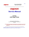
Disassembly, Reassembly and Lubrication
3-6-8. “Unit, Ribbon Sensor F/R” and “SA Ribbon Frame”
Caution
• DO NOT loosen the 10 screws of the “SA Ribbon Frame”. The “SA Ribbon Frame”
consists of three parts and is assembled with the 10 screws.
Once the “SA Ribbon Frame” is disassembled, correct ribbon running cannot be
assured. Therefore, a ribbon wrinkle may not be removed with the Ribbon Left-Right
Balance Adjustment Knobs (Front/Rear), as expected.
SA Ribbon Frame
5 screws
DO NOT LOOSEN
5 screws
DO NOT LOOSEN
1. Open the “Cover Top” Block and remove the “Unit, Ribbon”. Refer to “3-6-2 Unit, Ribbon”.
2. Remove the ribbon covers. Refer to “3-6-4(1) Removing the ribbon covers”.
3. Remove the 4 screws (No.0PH (4-0.3)M2x3 (NI)) and detach the “Cover Ribbon Tension
Sensor” (2 pcs.) on the front and rear sides.
4. On the front side, remove the 2 screws (BH, M3x4 (NI)) and detach the “Unit, Ribbon Sensor
F”.
5. On the rear side, remove the 2 screws (BH, M3x4 (NI)) and detach the “Unit, Ribbon Sensor
R”.
6. Peel off the “Label Ribbon Tension Adjust” from the “SA Ribbon Frame”.
No.0PH (4-0.3)M2x3 (NI)
BH, M3x4 (NI)
Cover Ribbon
Tension Sensor
Cover Ribbon
Tension Sensor
A
No.0PH (4-0.3)
M2x3 (NI)
B
BH, M3x4 (NI)
J104
Unit, Ribbon
Sensor F
J105
Unit, Ribbon Sensor R
Label Ribbon Tension Adjust
SA Ribbon Frame
DO NOT DISASSEMBLE
3-23
CL-S6621