1
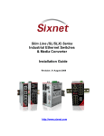
USER MANUAL Industrial Ethernet 5-Port IP67 Switch and RJ-Field™ RB Accessories Contents at a Glance: Section 1 General Information Page 4 Section 2 LED Indicators Page 7 Section 3 Installation Page 9 Section 4 Power Wiring Page 11 Section 5 Ethernet Wiring Page 14 Section 6 Ring Switch Features Page 15 Section 7 Ring Configurations Page 16 Section 8 Local and Remote Status Monitoring Page 20 Section 9 Default Settings Page 25 Section 10 Features and Capabilities Page 26 Section 11 Technical Specifications Page 28 Section 12 Service Information Page 30 This manual applies to the following products: ET-5RS-IP67 Series – 5 port IP67 industrial Ethernet ring switch ET-5ES-IP67 Series – 5 port IP67 industrial Ethernet unmanaged switch IP67 Switch User Manual Page 1 of 31 Last Revised: 12-Aug-09 Sixnet Technology Park 331 Ushers Road Ballston Lake, NY 12019 USA +1-518-877-5173 [email protected] Sixnet Protected Technology Policy: Sixnet protects your investment in Sixnet systems with long-term planned technology and our unique Protected Technology Policy. We will continue to support the specified capabilities of standard Sixnet products for at least five years. We plan each product improvement and new feature to be upward compatible with existing designs and installations. Our goals are to make each new software release bring new power to your Sixnet systems and have every existing feature, applications program and data file continue to work. We protect your investment even further with a liberal five-year trade-in policy. Exchange standard products for upgraded versions of the same product to take advantage of new features and performance improvements at any time for five years. A prorated trade-in allowance will be given for your existing equipment. Sixnet protects your long-term productivity with state-of-the-art planned technology and continued support. Sixnet Statement of Limited Warranty: Sixnet LLC, manufacturer of Sixnet products, warrants to Buyer that products, except software, manufactured by Sixnet will be free from defects in material and workmanship. Sixnet's obligation under this warranty will be limited to repairing or replacing, at Sixnet's option, the defective parts within one year of the date of installation, or within 18 months of the date of shipment from the point of manufacture, whichever is sooner. Products may be returned by Buyer only after permission has been obtained from Sixnet. Buyer will prepay all freight charges to return any products to the repair facility designated by Sixnet. This limited warranty does not cover losses or damages which occur in shipment to or from Buyer or due to improper installation, maintenance, misuse, neglect or any cause other than ordinary commercial or industrial applications. In particular, Sixnet makes no warranties whatsoever with respect to implied warranties of merchantability or fitness for any particular purpose. All such warranties are hereby expressly disclaimed. No oral or written information or advice given by Sixnet or Sixnet’s representative shall create a warranty or in any way increase the scope of this warranty. This limited warranty is in lieu of all other warranties whether oral or written, expressed or implied. Sixnet's liability shall not exceed the price of the individual units, which are the basis of the claim. In no event shall Sixnet be liable for any loss of profits, loss of use of facilities or equipment, or other indirect, incidental or consequential damages. INSTALLATION AND HAZARDOUS AREA WARNINGS: These products should not be used to replace proper safety interlocking. No software-based device (or any other solidstate device) should ever be designed to be responsible for the maintenance of consequential equipment or personnel safety. In particular, Sixnet disclaims any responsibility for damages, either direct or consequential, that result from the use of this equipment in any application. All power, input and output (I/O) wiring must be in accordance with Class I, Division 2 wiring methods and in accordance with the authority having jurisdiction. WARNING (EXPLOSION HAZARD) - SUBSTITUTION OF COMPONENTS MAY IMPAIR SUITABILITY FOR CLASS 1, DIVISION 2. WARNING (EXPLOSION HAZARD) - WHEN IN HAZARDOUS LOCATIONS, DISCONNECT POWER BEFORE REPLACING OR WIRING UNITS. WARNING (EXPLOSION HAZARD) - DO NOT DISCONNECT EQUIPMENT UNLESS POWER HAS BEEN SWITCHED OFF OR THE AREA IS KNOWN TO BE NONHAZARDOUS. IP67 Switch User Manual Page 2 of 31 Last Revised: 12-Aug-09 Sixnet Technology Park 331 Ushers Road Ballston Lake, NY 12019 USA +1-518-877-5173 [email protected] FCC Statement: This equipment has been tested and found to comply with the limits for a Class B digital device, pursuant to Part 15 of the FCC Rules. These limits are designed to provide reasonable protection against harmful interference in a residential installation. This equipment generates, uses and can radiate radio frequency energy and, if not installed and used in accordance with the instructions, may cause harmful interference to radio communications. However, there is no guarantee that interference will not occur in a particular installation. If this equipment does cause harmful interference to radio or television reception, which can be determined by turning the equipment off and on, the user is encouraged to try to correct the interference by one or more of the following measures: Reorient or relocate the receiving antenna; Increase the separation between the equipment and receiver; Connect the equipment into an outlet on a circuit different from that to which the receiver is connected; Consult the dealer or an experienced radio/TV technician for help. Copyright & Trademarks: Copyright Sixnet, All Rights Reserved. EtherTRAK is a registered trademark of Sixnet. RJ-Field is a registered trademark of Amphenol. Note: All information in this document is subject to change without notice. IP67 Switch User Manual Page 3 of 31 Last Revised: 12-Aug-09 Sixnet Technology Park 331 Ushers Road Ballston Lake, NY 12019 USA +1-518-877-5173 [email protected] Section 1 Switch Overview General Information This manual will help you install, configure and maintain the 5-port IP67 industrial Ethernet switches. These switches are offered in Ring or Unmanaged models. Both are completely plug and play and ready to go right out of the box. Unlike an Ethernet hub that broadcasts all messages out all ports, these advanced switches will intelligently route Ethernet messages only out the appropriate port. The major benefits of this are increased bandwidth and speed, reduction or elimination of message collisions, and deterministic performance when tied with real-time systems. These switches support both 10BaseT (10 Mbps) and 100BaseTx (100 Mbps) on their RJ45 ports. Each port independently auto-senses the speed, duplex, polarity and cabling (straight or crossed) make them truly plug and play. Accessory Overview This manual will help you install and maintain the IP67 industrial Ethernet accessories. These cables, connectors and plugs are design to meet the same rugged requirements as the switch. They utilize a Reverse Bayonet latching method which makes them quick and easy to install. The plugs are field-installable and don’t require any special tools. RJ-Field RB (Reverse Bayonet) IP67 Waterproof Accessories RJ45 Plug Power Plug Cap with Tether and Kevlar Protected Ethernet Cabling RJ45 Bulkhead IP67 Switch User Manual Kevlar Reinforced Cabling Page 4 of 31 Last Revised: 12-Aug-09 Sixnet Technology Park 331 Ushers Road Ballston Lake, NY 12019 USA +1-518-877-5173 [email protected] Ring Overview The Ring model has all the capabilities of the real-time unmanaged switch with the addition of rapid recovery ring support, priority queuing, port mirroring and more. The Ring Switch allows you to implement the traditional star topology or a ring topology to take advantage of network path redundancy. The switch can be used right out of the box without configuration; or through some simple configuration steps, some powerful managed switch features can be enabled such as traffic prioritization and port mirroring. Ring Operation In the Ring model, messages are intelligently routed for the sake of increasing the efficiency and reliability of your network. Unlike an Ethernet hub, a switch will forward packets to specific ports to reduce unnecessary traffic on network paths, thus optimizing network efficiency. Most importantly, by using a Ring Switch, you can implement redundant paths in a network by allowing ring topology (for a more resilient network). Ring topology is important in path redundancy because no matter where in the ring that a path gets “cut”, all devices connected to a node in the ring will still be able to communicate with each other. The unmanaged model cannot be used in ring topologies because of broadcast storms. Broadcast storms can bring a network to a stop if conventional switches or hubs are being used in a ring topology because of broadcast message reproduction. Using Ring Switches in the loop will prevent broadcast storms because they have the intelligence to detect loops and to assign the necessary ports to be in the backup (disabled) state. These backup ports will be instantly enabled should the primary path in their respective ring fail. IP67 Switch User Manual Page 5 of 31 Last Revised: 12-Aug-09 Sixnet Technology Park 331 Ushers Road Ballston Lake, NY 12019 USA +1-518-877-5173 [email protected] Performance Specifications Standards and Safety These general specifications apply to the 5-port IP67 Industrial Ethernet Switches. Refer to Section 7 for complete technical specifications. Ports 5 Port types 10/100BaseT (shielded RJ45) Switch type Intelligent store and forward Ring model Rapid ring recovery, priority queuing and more Protocols supported All IEEE 802.3 RJ45 operation Auto negotiation, auto-crossover and auto-polarity The IP67 Industrial Ethernet Switch meets the following standards: Electrical safety - UL 508, CSA C22/14; EN61010-1 (IEC1010) EMI emissions - FCC part 15, ICES 003, EN55022; Class B EMC immunity – IEC61326-1 Hazardous locations – UL 1604, CSA C22.2/213 (Class 1, Div. 2), Groups A, B, C, D; Cenelec EN50021 (Zone 2) EEx nA II T4 X (-40°C ≤ Ta ≤ +85°C) Install the IP67 Industrial Ethernet Switch in accordance with local and national electrical codes. Lightning Danger: Do not work on equipment during periods of lightning activity. Do not connect a telephone line into one of the Ethernet RJ45 connectors. IP67 Switch User Manual Page 6 of 31 Last Revised: 12-Aug-09 Sixnet Technology Park 331 Ushers Road Ballston Lake, NY 12019 USA +1-518-877-5173 [email protected] Section 2 Overview LED Indicators The IP67 Industrial Ethernet Switch has communication LEDs for each port and power LEDs for each input terminal. In addition, on ring models two LEDS (OK and Ring) provide switch and network status. Refer to the pictures below for the LED locations. Unmanaged IP67 Industrial Ethernet Switch Ring IP67 Industrial Ethernet Switch Power LEDs There are two power LEDs on the switch that are labeled as P1 and P2. These indicate if primary and/or secondary power is present. OK LED (ring model) Ring model only: The OK LED is a multifunctional indicator, which has several states defined below. Note: The OK LED and OK Output do not always coincide. In general the OK LED will always indicate any type of error condition. However, the OK Output can be configured using the Ethernet Switch Tools to only indicate the errors you define. ON solid: The OK LED will be in a steady ON state when both P1 and P2 power inputs are powered and that all configured rings have continuous ring integrity. OFF completely: The OK LED will be OFF if either P1 and/or P2 are not powered, or if any one of the active rings for which this switch is a member of encounters a segment failure. Blinking: The OK LED can blink at different rates. Continuous rapid blinking: To verify communication and target switch selection, you can request the switch to “wink” its OK LED to visually identify the unit. Rapid blinking, with a single short pause: Should the OK LED blink rapidly for about 5 sec and then pause for about 1 second, this indicates that the switch is in the boot-up process such as on power-up, when loading firmware or when resetting the switch. Long OFF, short ON: If the OK LED is OFF for about 1.9 seconds and ON for .1 seconds, an internal error has occurred in the unit. Try cycling power or resetting the switch from the configuration utility. IP67 Switch User Manual Page 7 of 31 Last Revised: 12-Aug-09 Sixnet Technology Park 331 Ushers Road Ballston Lake, NY 12019 USA +1-518-877-5173 [email protected] Ring LED (ring model) Ring model only: The Ring LED is a multifunctional indicator that shows four states. ON solid: The Ring LED will be ON when all rings enabled in the switch have continuous ring integrity. OFF completely: The switch has not been configured for any rings. Blinking: (50% OFF – 50% ON) One or more rings have been configured for the switch, but a break has been discovered for one or more of the configured rings. Neighboring Ring Switches are responding, so the break is at another location. Blip: (Long OFF – Short ON) One or more configured rings have been broken. The break has been detected to be local to one of the ports. Diagnostically speaking; in simple rings, the segment with the problem will be between the two switches with their ring LEDs in the blip state. Also, you can ascertain the general location of where the segment error has occurred with a HMI, a master controller, or some other MODBUS Master through MODBUS over Ethernet polling. Find out more details about MODBUS diagnostics in section 7 of this manual. ACT / LNK/ 10/100 Mbps LEDs Activity, link, and port speed indication is combined into one LED per port. The port states are described below: ON solid: This would indicate that there is a proper Ethernet connection (Link) between the port and another Ethernet device, but no communications activity is detected. OFF completely: This would indicate that there is not a proper Ethernet connection (Link) between the port and another Ethernet device. Make sure the proper cable type is in use and that it has been plugged securely into the ports at both ends. See section 5 for proper Ethernet cabling. Blinking: This would indicate that there is a proper Ethernet connection (Link) between the port and another Ethernet device, and that there is communications activity. Red: 1000 Mbps (1000BaseT) connection is detected. Green: 100 Mbps (100BaseT) connection is detected. Yellow: 10 Mbps (10BaseT) connection is detected. IP67 Switch User Manual Page 8 of 31 Last Revised: 12-Aug-09 Sixnet Technology Park 331 Ushers Road Ballston Lake, NY 12019 USA +1-518-877-5173 [email protected] Section 3 Switch Installation Installation The IP67 Industrial Ethernet Switch can be fastened to any flat surface by using the supplied mounting ears or by mounting the box directly. Refer to the mechanical drawings below. Make sure to allow enough room to route your Ethernet and power cables. Note: The switch is typically shipped with the mounting ears unattached. To attach these ears or to mount the box directly you must remove the four cover screws and remove the cover. Then use the supplied screws to attach the mounting ears, or mount the box base directly to any flat surface. When replacing the cover make sure to tighten the cover screws evenly and firmly to ensure a water-tight seal. Use these holes to mount the box directly (without ears). You must remove the cover to access these holes. Switch Mechanical Dimensions IP67 Switch User Manual Page 9 of 31 Last Revised: 12-Aug-09 Sixnet Technology Park 331 Ushers Road Ballston Lake, NY 12019 USA +1-518-877-5173 [email protected] RJ45 Plug Installation The IP67 rated RJ45 plug is field installable and does not require any special tools. It can be installed over most standard Ethernet patch cables (Though you may have to remove the latch cover if it has an over-molded boot). Refer to the diagrams for mechanical and assembly details. Cable Diameter: 0.2” (5 mm) min. 0.4” (10 mm) max. RJ45 Plug Mechanical Dimensions To ensure a water-tight seal, make sure to tighten firmly! IP67 Switch User Manual RJ45 Plug Assembly Page 10 of 31 Last Revised: 12-Aug-09 Sixnet Technology Park 331 Ushers Road Ballston Lake, NY 12019 USA +1-518-877-5173 [email protected] Power Plug Installation This IP67 rated power plug is assembled around a suitable power cable as shown below. Heat-wrap shrinking the soldered connections is recommended. To ensure a water-tight seal, make sure to tighten firmly! Power Plug Mechanical Dimensions Power Plug Assembly Two rubber inserts are provided that allow for cable diameters of: 0.25” (6.4mm) (max. cable diameter) to 0.125” (3.2mm) (min. cable diameter) Choose the one that best fits your cable. Power Plug Rubber Gasket Inserts Power 2 + (P2) Power 1 + (P1) OK Output (ring models) Power – Chassis Ground Solder side of plug shown Power Plug Wiring IP67 Switch User Manual Page 11 of 31 Last Revised: 12-Aug-09 Sixnet Technology Park 331 Ushers Road Ballston Lake, NY 12019 USA +1-518-877-5173 [email protected] Bulkhead Installation The IP67 rated bulkhead connector allows you to make a watertight Ethernet connection through any flat surface such as the side walls of industrial enclosure. The maximum wall thickness supported is 0.126” (3.2 mm) and the minimum recommended is 0.063” (1.6 mm). Bulkhead Mechanical Dimensions IP67 Switch User Manual Page 12 of 31 Last Revised: 12-Aug-09 Sixnet Technology Park 331 Ushers Road Ballston Lake, NY 12019 USA +1-518-877-5173 [email protected] Cap Installation The IP67 rated cap comes with a universal tether that can be used with either the switch or the bulkhead connector. For use with the switch, simply remove the jam nut, put the ring of the tether over the connector and reinstall the jam nut. For use with the bulkhead, simply cut off the ring part of the tether, and plug the tether line into the mating hole on the connector. For bulkhead, cut ring off here (before first nub) lP67 Cap Mechanical Dimensions Installing Cap on Switch Installing Cap on Bulkhead lP67 Cap Assembly IP67 Switch User Manual Page 13 of 31 Last Revised: 12-Aug-09 Sixnet Technology Park 331 Ushers Road Ballston Lake, NY 12019 USA +1-518-877-5173 [email protected] Section 4 Overview Power Wiring The IP67 switch can be powered from the same DC source that is used to power your other industrial devices. An IP67 Switch that has a part number ending with a ‘-D’ will accept power within the 10-30 VDC range. For extended power IP67 Switches (indicated by a ‘E’ in the part number), 10-50 VDC can be applied to the power terminals. Verify the power rating of your Ring Switch by checking the part number on the side label. Primary power is applied to P1 and the minus pin. The center pin should be tied to panel or chassis ground. To prevent possible down time resulting from power loss, a second power pin (P2) is provided for redundant power. The OK (alarm) output (ring models) is accessed on the remaining pin. Note: If you wish to use the alarm output (pin marked ‘OK’), but only have a single power source, just jumper the power to both incoming power pins (P1, P2). See below. The alarm output in the ON state has the same voltage as the applied input. Ring Model Unmanaged Model Power Plug and Power LED Locations Power 2 + (P2) Power 1 + (P1) OK Output (ring models) Power – Chassis Ground Solder side of plug shown Power Plug Wiring IP67 Switch User Manual Page 14 of 31 Last Revised: 12-Aug-09 Sixnet Technology Park 331 Ushers Road Ballston Lake, NY 12019 USA +1-518-877-5173 [email protected] Section 5 Ethernet Wiring and Cabling Overview The IP67 switch provides Ethernet connections to devices on the factory floor through star or ring topology. When wiring a ring topology, it is important that only Ring Switches are used for each node in the ring. With proper ring wiring, all nodes in the ring can maintain the same data connectivity should a path in the ring be “cut”. Be sure to visit Section 8 for detailed examples about valid and invalid ring topologies. RJ45 Wiring Guidelines Use data-quality (not voice-quality) twisted pair cable rated category 5 or better with standard RJ45 connectors. For best performance use shielded cable. Straight through or crossover category 5 cable can be used regardless of the type of device connected to the Ring Switch. This is because the Ring Switch supports auto-mdi/mdix-crossover. Ethernet Cable Pin-outs (for reference only) Straight-thru Cable Wiring Pin 1 Pin 1 Pin 2 Pin 2 Pin 3 Pin 3 Pin 6 Pin 6 Cross-over Cable Wiring Pin 1 Pin 3 Pin 2 Pin 6 Pin 3 Pin 1 Pin 6 Pin 2 Ethernet Connector Pin Positions Ethernet Cabling Cable Distance The maximum cable length for 10/100/1000 BaseT is typically 100 meters (328 ft.). The use of industrial rated Ethernet cables is highly recommended for best overall system performance. Kevlar Reinforced Ethernet Cabling: Kevlar means superior strength High flexibility for easy routing Low smoke, halogen free, flame retardant – extra safe! Excellent resistance to UV, hydrolysis and microbial Double shielded with gold contacts The toughest Ethernet cable in the World! Available in Bulk Reels or Pre-assembled Cordsets Contact your IP67 Switch Provider for Details IP67 Switch User Manual Page 15 of 31 Last Revised: 12-Aug-09 Sixnet Technology Park 331 Ushers Road Ballston Lake, NY 12019 USA +1-518-877-5173 [email protected] Section 6 Overview Real-time Ring™ Switch Features (ring model only) The IP67 Ring Switch has all the networking capability of the unmanaged model plus some advanced capability that you would only find in a managed switch. Like the unmanaged model, the Ring Switch is “plug and play” meaning that it can be used right out of the box without any user configuration. This includes the ring functionality, which is already preconfigured in the switch. For most applications this is all that is needed. For advanced applications you can use the Ethernet Switch Tools (Windows software utility) to enable some advanced capabilities such as priority queuing for prioritizing your traffic, message rate filtering for broadcast storm protection and port mirroring for diagnostics. Important Note: Only use Real-time Ring™ Switches when connecting switches in a ring. The Real-time Ring™ Switches use a specialized high-speed ring algorithm that only they will understand. Otherwise, these Ring Switches are fully IEEE 802.3 compatible. Ring Setup & Operation For ring operation in most applications, no user configuration is necessary. The Ring Switches can be ordered pre-configured with 1 or more pairs of ports setup for ring operation. Just connect the ring-configured ports of your Ring Switches in a ring by connecting the last switch back to the first. Make sure you use only the ring configured ports for your ring connections. The non-ring ports should be used to connect to your Ethernet devices such as PLCs, computers, etc. Be sure to visit Section 8 for great examples about valid and invalid ring topologies. IP67 Switch User Manual Page 16 of 31 Last Revised: 12-Aug-09 Sixnet Technology Park 331 Ushers Road Ballston Lake, NY 12019 USA +1-518-877-5173 [email protected] Ring Algorithm and Performance The Real-time Ring™ feature utilizes a special algorithm that assures very fast recovery times. Each Real-time Ring switch utilizes the special high-speed algorithm to keep track of the health of the ring. In a healthy ring (a complete ring), one ring switch will be automatically picked to act as a master (switch with lowest MAC address) for the ring network. Alternatively, you can designate one of your ring switches to be the master using the Ethernet Switch Tools. It is the master switch’s job to determine which one of its local ring ports are to be in the forwarding or backup state. The ring port chosen to be in the backup state is where the backup segment of the ring will be. By default, the ring port with the higher port number will get become the backup port. All ring switches in the ring must have a way to keep track of each other in case a failure in communication occurs along the ring. To keep track of the health of the ring, the Ring switches periodically send test messages to each other. Therefore, when a ring gets “cut” at a certain location, the Ring switches will know and they will take the appropriate action to bring the network back online. The time that it takes for the last Ring switch to “know” and take appropriate action to rectify the communication problem will be when the link loss “recovers”. Recovery time can be estimated by multiplying 5 mS times the number of switches, and then adding 30 mS (for loss of link errors) or 60 mS (for message loss errors). For example, a ring of 10 switches would have a recovery time of 80 mS for the typical loss of link type errors. Master Switch Selection As mentioned above, the ring switch with the lowest MAC address will automatically become the master and block one of its ports (highest number port). Alternatively, you can designate one of your ring switches to be the master using the Ethernet Switch Tools. There is a simple check box where you can select “Automatic” or “This Switch” for the master ring switch selection. This advanced capability allows you to control where the backup port will be in your network. The ring switch to be designated the master must be running firmware v0103 or newer. Only the ring switch that is designated the master needs to be running the newer firmware. All other ring switches can be running older firmware. It is recommended that only one ring switch be designated as the master. If more than one is designated as the master then the one with the lowest MAC address will prevail. Ethernet Switch Tools In some applications it may be desirable or required to adjust the Ring Switches parameters for proper or best operation. A Microsoft Windows software utility called the Ethernet Switch Tools is provided to make these adjustments. Using the “auto-find” feature in the utility, you will be able to pick from a list of detected Ring Switches and load custom configurations via Ethernet. The auto-find feature eliminates the hassle of loading via a serial connection and the overhead time spent assigning IP addresses. Refer to the online help for details on using the Ethernet Switch Tools. Hot Tip: Refer to the Ethernet Switch Tool’s comprehensive on-line help for more details. Port Configuration IMPORTANT NOTE: Your computer must be on the same local network as the Ring Switch for the Ethernet Switch Tools to operate properly. Also, your computer must have updated Raw Ethernet Socket (WinPcap) support installed. When installing the Ethernet Switch Tools, the installation program will call the WinPcap installation program if necessary. If you have an older version of WinPcap installed, the installation program will prompt you to remove the older version before continuing with the installation. Ring Switches auto-negotiate port settings. In most applications port settings are best left in the default "Auto" connection mode. For special situations, the ports can be "Fixed" to restrict communications to only 10 or 100 Megabits per second, with either half or full duplex. Flow control can be enabled or disabled as well. Port configuration settings are adjustable using the Ethernet Switch Tools. IP67 Switch User Manual Page 17 of 31 Last Revised: 12-Aug-09 Sixnet Technology Park 331 Ushers Road Ballston Lake, NY 12019 USA +1-518-877-5173 [email protected] Fault Tolerant Rings A network backbone wired in a ring type topology is one of the best choices for a faulttolerant network. By default, Ring Switches may be factory preset to have zero, one (standard default), or two rings enabled. Factory presetting a ring configuration skips the step of using the Ethernet Switch Tools to enable your rings so you can have the convenience of “plug and play” operation. Contact your IP67 switch provider for details. To change the ring configuration in the switch, simply launch the Ethernet Switch Tools and choose the desired pair of ports for your new enabled ring. The Ring LED will be lit if all rings (one or two) that are enabled in this switch have continuous ring integrity. For a ring to function, all switches in the path of the ring must have Real-time Ring™ support. Do not connect rings within rings. Only simple non-overlapped rings are allowed. Two active rings cannot share a network segment. It is possible to join two rings together by configuring two rings in a single switch. The ports used for each ring must be distinct, so that no network segment is shared by both rings. See Section 7 for ring wiring examples and guidelines. Message Rate Filtering (Broadcast storm protection) Poorly configured applications and devices or malicious users can flood your network with broadcast packets that are forwarded to all ports and can quickly consume most of a network’s bandwidth. The Ring Switch provides protection against broadcast storms by limiting the quantity of broadcast and multicast messages. This protection is enabled by default. See Ethernet Switch Tool’s on-line help for details. Priority Queuing With priority queuing configured in the Ring Switch, low priority data will not interfere (Traffic Prioritization using QoS, CoS, ToS/DiffServ) with your time critical data again. Network traffic can be prioritized to achieve the performance that time-sensitive data demands. Refer to the Ethernet Switch Tool’s on-line help for more information and details on configuring priority queuing. Port Mirroring This advanced diagnostic capability allows messages from one or more ports to be copied to another port. Then a port analyzer or “sniffer” program can be used to monitor the traffic without affecting the operation of the switch. Configuring the Ring Switch for port mirroring is done through the Ethernet Switch Tools. See the on-line help for details. Note: With firmware 0103 or newer, only one monitor (destination) port is allowed. However, multiple source ports can be chosen. IP67 Switch User Manual Page 18 of 31 Last Revised: 12-Aug-09 Sixnet Technology Park 331 Ushers Road Ballston Lake, NY 12019 USA +1-518-877-5173 [email protected] Section 7 Ring Configurations (ring models) Configuring Rings in your Ring Switch First and foremost, make sure that ring operation is enabled for the appropriate ports. In other words it is required to tell the Ring Switch what ports it is going to use as ring ports (unless the Ring Switch was purchased with rings pre-configured). Never wire a Ring Switch in a ring topology without having the ports that are used in the ring configured as ring ports (See diagram below). Valid Ring Topologies Below are examples of how you should wire your Ring Switches together. In general, you should keep your topology simple. IP67 Switch User Manual Page 19 of 31 Last Revised: 12-Aug-09 Sixnet Technology Park 331 Ushers Road Ballston Lake, NY 12019 USA +1-518-877-5173 [email protected] Invalid Ring Topologies The examples below are invalid ring topologies. Do NOT connect Ring Switches in the ways shown below, as they will lead to unpredictable network performance. Paths indicated by the color red create unintended rings (see unintended rings example below). IP67 Switch User Manual Page 20 of 31 Last Revised: 12-Aug-09 Sixnet Technology Park 331 Ushers Road Ballston Lake, NY 12019 USA +1-518-877-5173 [email protected] Unintended Rings Example Refer to the diagram below. In this example, Ring Switches A and B have been software configured for two rings each. Ring Switches C and D have been software configured for one ring each. The physical connections for the two rings are shown in blue and red. Since the rule for configuring Ring Switches is to make sure that each Ring Switch knows about all rings that are attached to it, it would appear that the example below is legal. However, this is not the case. There are actually more than two ring paths that were created. There are multiple paths that traffic can use to move from Switch A and back to Switch A. The same applies to Switch B. These unintended Ring paths that Switch A and Switch B don’t know about are labeled as Unintended Rings A, B, C, and D. Since Ring Switch A and Ring Switch B don’t know about these extra ring paths, they aren’t included in A or B’s ring algorithm. Paths that are not included in the ring algorithm will result in harmful broadcast storms, as will happen when conventional switches are connected in a ring topology. IP67 Switch User Manual Page 21 of 31 Last Revised: 12-Aug-09 Sixnet Technology Park 331 Ushers Road Ballston Lake, NY 12019 USA +1-518-877-5173 [email protected] Section 8 Local and Remote Status Monitoring Switch Status You can keep track of the status of your Ring Switches at all times. To check the status of a Ring Switch visually, you can monitor the Ring Switch’s indicator LEDs. To monitor the status remotely, you can use Modbus over Ethernet (UDP or TCP). There is also an alarm output that can be tied to a PLC or other supervisory device. Visual Status Monitoring The status of your Ring Switches can be easily ascertained by simply looking at their LED indicators. The LEDs can be used to quickly see the status or to locate a network problem. See Section 2 for details on the LED indicators. Port Status (ACT/LNK LED) After all Ethernet and/or fiber connections are made, check the LED’s corresponding to the ports that each of the devices are connected to. Ensure that for each port that is in use, the LED is on or blinking. If a port LED is off, go back and check for connectivity problems between that port and the network device connected to that particular port. In addition, the color of the LED should indicate the speed for which your device is connected at (yellow – 10Mbps, green – 100Mpbs). Power & Switch Status (OK LED) The Ring Switch has an OK LED that indicates the power and operational status. It is ON solid when there are no errors. It will go OFF if either power supply fails or a ring break is detected. The OK LED will also flash if the switch is being “winked”, is in the boot-up mode, or an internal error was detected. Ring Status (Ring LED) The Ring Switch has a Ring LED that indicates the status of your ring connections. It is ON solid when all rings handled by the switch have continuous integrity. It will be blinking if there is broken ring segment but all adjacent switches are responding. It will be OFF if the switch is not configured for any rings. The ring LED will Blip (mostly OFF, with a quick ON) when a configured ring has been broken and the break is local to one of the ports of the switch. Typically the network with the fault will be between the two switches with Ring LEDs in the Blip state. This makes tracking down faults quick and simple. Ring Switch User Manual Page 22 of 31 Last Revised: 12-Aug-09 Sixnet Technology Park 331 Ushers Road Ballston Lake, NY 12019 USA +1-518-877-5173 [email protected] OK Output The Ring Switch has an OK Output that can be used to signal an error to a PLC, PC or other supervisory devices. By default, this output is normally ON when both power inputs are present and there are no ring errors. The output will go OFF if either power input fails, both power inputs fail or there is a ring break detected. Alternatively, using the Ethernet Switch Tools you can define which error conditions will cause the OK Output to go OFF. Remote Status Monitoring There are two ways to remotely monitor the status of your Ring Switch network. The first method is to use the Ethernet Switch Tool’s status display. This display will show the status of the selected Ring Switch by providing details such as port, power, and ring states. Find more details about how to use this display by referring to the Ethernet Switch Tool’s on-line help. The second method that can be used for determining the state of your Ring Switch network is via Modbus/TCP or Modbus/UDP. See the Modbus topic below for detailed information about how to take advantage of this feature. Modbus over Ethernet Through Modbus over Ethernet (UDP or TCP), you can remotely monitor the status of the Ring Switch. Using the Ethernet Switch Tools, the Ring Switch can be configured as a Modbus slave station with its own Modbus station number and IP address. The Ring Switch has a set of predefined Modbus registers for status reporting. Refer to the table below for the register assignments. Modbus Address Modbus Address Status Status 10001 Link on port 1 10019 Ring 1: Second port is passing data (not blocked) 10002 Link on port 2 10020 Ring 2 complete 10003 Link on port 3 10004 Link on port 4 10021 Ring 2: First port is passing data (not blocked) 10005 Link on port 5 10006 Link on port 6 10022 Ring 2 second port is passing data (not blocked) 10007 Link on port 7 10008 Link on port 8 10030 10009 Link on port 9 OK output ON (no alarms) Output will be ON if both power and all enabled rings are complete. 10017 Ring 1 complete 10031 First power input valid 10018 Ring 1: First port is passing data (not blocked) 10032 Second power input valid NOTE: It is recommended that you keep the poll time of your Modbus master driver or hardware device to a reasonable rate. If you poll a Ring Switch at a rapid rate, the performance of the switch may be reduced. The fastest poll time you should run will depend on the application. As a guideline, a poll time of 500 mS or greater should not adversely affect the performance of your Ring Switch. Ring Switch User Manual Page 23 of 31 Last Revised: 12-Aug-09 Sixnet Technology Park 331 Ushers Road Ballston Lake, NY 12019 USA +1-518-877-5173 [email protected] Modbus Diagnostics Example As an example of how to debug a network using the Modbus registers, we will examine a simple ring topology, which is shown in the figures that follow. Scenario 1: No Breaks Taking a look at the diagram below, we see three Ring Switches. Ring Switches A, B, and C have been configured for one ring. The ring network is currently in good health (no breaks in the ring) with the solid blue line indicating the active part of the ring, and the dashed blue line indicating the standby part of the ring. Figure 6a Since the ring network is in good health, we would expect these values from the Modbus registers of each switch: Switch A Ring 1 Complete: 1 First Port of Ring 1: 1 Second Port of Ring 1: 1 Switch B Ring 1 Complete: 1 First Port of Ring 1: 1 Second Port of Ring 1: 1 Switch C Ring 1 Complete: 1 First Port of Ring 1: 0 Second Port of Ring 1: 1 A ring network in good health would have the Ring Complete bit set to one in all Ring Switches. Also, all ports in the ring should be forwarding except for one port that should be in backup mode. The backup port will indicate the standby/backup path of the existing ring. Ring Switch User Manual Page 24 of 31 Last Revised: 12-Aug-09 Sixnet Technology Park 331 Ushers Road Ballston Lake, NY 12019 USA +1-518-877-5173 [email protected] Scenario 2: A Network Break Should the ring experience a break like the diagram indicated below (Figure 6b), we immediately see that the Ring Complete bits for each switch have gone to zero. The port that was in the backup state will rapidly change to the forwarding state to activate the standby Ethernet path. Figure 6b With the break indicated above, we would expect these values from the Modbus registers of each switch: Switch A Ring 1 Complete : 0 First Port of Ring 1 : 1 Second Port of Ring 1 : 0 Switch B Ring 1 Complete : 0 First Port of Ring 1 : 0 Second Port of Ring 1 : 1 Switch C Ring 1 Complete : 0 First Port of Ring 1 : 1 Second Port of Ring 1 : 1 With the ring broken, each ring port reports whether its ring partner is available. In the example above, we see that for switch A, the ‘First Port of Ring 1’ has a value of one. This means that switch A can talk to its ring partner (Ring Switch C). For the same switch, we see that the ‘Second Port of Ring 1’ has a value of zero. This means that switch A is not able to talk to its ring partner for that port (Ring Switch B). Based on this information, you can localize where a break in a ring has occurred by checking which ports report back with zero when a ring is broken. Ports that report back with zero mean that the break is local to that particular port. Ring Switch User Manual Page 25 of 31 Last Revised: 12-Aug-09 Sixnet Technology Park 331 Ushers Road Ballston Lake, NY 12019 USA +1-518-877-5173 [email protected] Section 9 Default Settings (ring model) About Default Settings The settings below are the factory defaults when the switch comes out of the box. Use this page to find out what changes may be necessary for tailoring the switch to your exact needs. Ring Ports 1 Ring configured on last two ports (4 and 5) Master ring switch selection: Automatic Port Configuration (all ports): Port # Broadcast Limit Enabled on all ports Port Mirroring Mirroring: Disabled Priority Queuing Use 802.1p Tag Priority: Enabled Use IP ToS/DiffServ: Enabled Priority Precedence: Tag Default Priority: Normal Output Tag: Unchanged IEEE Tagging Name Port_1 Priority 0 1 2 3 4 5 6 7 Admin Negotiation Speed & Duplex Enabled Auto 10h 10f 100h 100f Traffic Type Best Effort Background Spare Excellent Effort Controlled Load Video Voice Network control Flow Control Disabled Queue 0 0 0 1 1 1 1 3 OK Output The OK Output will be normally ON and go OFF when either the power input is not present, both power inputs are not present or a ring failure is detected. Modbus Modbus monitoring: Disabled Modbus address = 1 IP address = blank Subnet mask = 255.255.255.255 Default gateway = blank TCP/IP sessions at one time = 4 TCP/IP timeout = 0 mS IP67 Switch User Manual Page 26 of 31 Last Revised: 12-Aug-09 Sixnet Technology Park 331 Ushers Road Ballston Lake, NY 12019 USA (518) 877-5173 [email protected] Section 10 General Features and Capabilities Features & Capabilities This section explains the primary Ethernet and fiber capabilities of the Ring Switch. 10BaseT, 100BaseT Auto-detection Standard Ethernet (10BaseT) has a maximum speed of 10 Mbps (half duplex mode) or 20 Mbps (full duplex mode). Fast Ethernet (100BaseT) has a maximum speed of 100 Mbps (half duplex mode) or 200 Mbps (full duplex mode). The 10/100 RJ45 ports automatically support both speeds. 2K MAC addresses with automatic learning, aging and migration Each Ethernet device inserts its unique “MAC” address into each message it sends out. The port on the switch used for a given MAC address is automatically learned when a frame is received from that address. Once an address is learned, the switch will route messages to only the appropriate port, instead of broadcasting messages out all ports like a hub. A time stamp is also placed in memory when a new address is learned. This time stamp is used with the aging feature, which will remove unused MAC addresses from the table after 300 seconds. If a device moves, the associated port on the switch will be changed (migrated) as needed. Up to 2K MAC addresses can be stored and monitored at any time. 3.2 Gbps combined bandwidth The fast Ethernet switches have 3.2 Gbps of combined bandwidth. This means that they can support full duplex communications on all ports at the same time. Auto-crossover (auto-mdi/mdix) The RJ45 ports of the switch will automatically detect the cable type (straight-thru vs. cross-wired) and re-configure themselves accordingly. Auto-polarity The auto-polarity feature corrects reversed polarity on the transmit and receive twisted pair. Automatic power saving If there is no cable on a port, most of the circuitry for that port is disabled to save power. Auto-sensing speed and flow control The RJ45 ports of the switch will auto-negotiate with the connected device to determine the optimal speed and flow control for each port. Back pressure for half-duplex The switch will apply “back pressure” when necessary with half-duplex operation. This “back pressure” will reduce congestion on busy networks. Broadcast storm protection Each port can be configured to filter out undesirable broadcast and multicast messages. Buffering SRAM is used for buffering the messages. The Ring switches have 1 Mbits (128 Kbytes) and the unmanaged switches have 0.5 Mbits (512 Kbytes). The buffer size is automatically allocated for each port as necessary. Flow control These switches automatically support flow control frames on both the transmit and receive sides. Back-pressure flow control for half-duplex ports and pause-frame flow control for full-duplex ports. IP67 Switch User Manual Page 27 of 31 Last Revised: 12-Aug-09 Sixnet Technology Park 331 Ushers Road Ballston Lake, NY 12019 USA (518) 877-5173 [email protected] Forwarding These switches support store and forward mode. They will forward messages with known addresses out only the appropriate port. Messages with unknown addresses, broadcast messages, and multicast messages will get forwarded out all ports except the source port. Full / Half duplex operation The RJ45 ports of these switches support both full and half duplex operation. The fiber optic port(s) are full duplex but can be interfaced to device with half or full duplex. Illegal frames Illegal frames as defined by IEEE 802.3 will be dropped. This includes short frames, long frames, CRC error frames and alignment error frames. IEEE 802.3 compliant These switches strictly abide to the IEEE 802.3 standard for 10BaseT and 100BaseT Ethernet communications. Latency The typical latency of a message is 5 microseconds (@ 100 Mbps) plus the frame time. The latency is the time it takes a message to be routed internal to a switch from one port to another. This time is highly dependent on the amount of network activity, the speed and the features enabled in the switch. Non-blocking This means that the switches offer the best in performance and are capable of full-wire speed transmissions. Port Mirroring Powerful diagnostic mode that lets you map messages between ports. Plug and play This means that most functions or features of these switches are automatic and that there are minimal or no optional parameters that need to be set. Just plug in your Ethernet cables, apply power, and the unit will immediately begin to operate. The Ring Switches can even be factory pre-configured to your exact needs. Priority queuing or Traffic Prioritization The Ring models support QoS (Quality of Service), CoS (Class of Service), ToS (Type of Service), and DS (Differentiated Services) mechanism for ensuring the priority traffic is handled properly. These advanced parameters can be set via the configuration utility. Protocol independent These switches will work with all popular Ethernet protocols and networks such as TCP/IP, the Internet (IP), UDP, NetBEUI, and many more. It is compatible with all protocols that run over standard Ethernet (IEEE 802.3). In fact, it will support packets of different protocols simultaneously. IP67 Switch User Manual Page 28 of 31 Last Revised: 12-Aug-09 Sixnet Technology Park 331 Ushers Road Ballston Lake, NY 12019 USA (518) 877-5173 [email protected] Section 11 Technical Specifications Technical Specifications Here are the technical specifications for the IP67 Industrial Ethernet Switch. General Ethernet switch type Ethernet protocols supported RJ45 ports (shielded) RJ45 speed (10 or 100 Mbps) RJ45 MDI/MDIX RJ45 TD and RD polarity Typical latency @ 10 Mbps Typical latency @ 100 Mbps Full or half duplex operation MAC addresses supported Memory bandwidth Status Reporting (RS model) Modbus status registers “OK” contact output Real-Time Ring™ Features Maximum switches in ring Dual ring support Link loss recovery time Environmental Power input Input power (typical) Input voltage (-D models) Transient protection Spike protection Input voltage (-E models) Extended power protection Military surge protection Transient protection Spike Protection Ethernet isolation Operating temperature range Storage temperature range Humidity (non-condensing) Vibration, shock and freefall Electrical safety EMI emissions EMC immunity Hazardous locations Marine and off-shore Protection rating Enclosure material Dimensions and mounting Weight IP67 Switch Performance Specifications 5 Ethernet ports Intelligent store & forward All IEEE 802.3 10/100BaseTX Auto-negotiation Auto-crossover Auto-polarity 16 us + frame time Varies on load & settings 5 us + frame time Configurable 2048 3.2 Gbps Power & operational status Modbus Ethernet over UDP Sourcing power @ 0.5 Amp Ring models 50+ Yes 30 mS plus 5 mS per hop Full industrial ratings Redundant input connections ES: 2.4 W, RS: 2.7 W 10-30 VDC 15,000 watts peak 5,000 watts (10 times for 10 uS) 10-50 VDC (Derate 1.8°C / V above 30V) -E models Exceeds MIL-STD-1275; 100 volts for 1 second 15,000 watts peak 5,000 watts (10x for 10 uS) or 250 volts (50x for 100 uS) 1500 VRMS 1 minute -40 to +75 °C -40 to +85 °C 5 to 95% RH IEC68-2-6, -27 and -32 UL508/CSA C22, EN61010-1 FCC part 15, ICES-003, EN55022 IEC61326-1 UL1604, CSA C22.2/213, Cenelec EN50021(Class 1, Div. 2) (Zone 2) DNV (Det Norske Veritas) IP67 and NEMA 6 Fiber reinforced polyester See mechanical diagram 1.2 lbs (0.54 kg) Specifications are subject to change. Consult factory for latest information. IP67 Switch User Manual Page 29 of 31 Last Revised: 12-Aug-09 Sixnet Technology Park 331 Ushers Road Ballston Lake, NY 12019 USA (518) 877-5173 [email protected] IP67 RJ-Field RB Accessories Performance Specifications Electrical characteristics Ethernet data rates supported Cat 5E cable supported per Cat 6 cable supported per 10BaseT, 100BaseT, 1000BaseT TIA/EIA 568B and ISO/IEC 11801, Class D TIA/EIA 568B and ISO/IEC 11801, Class E Mechanical characteristics Coupling (connection method) RJ45 cordset retention Mating cycles Reverse bayonet – just a quarter turn and lock 70 N in the axis 500 minimum Environmental protection Sealing protection Salt spray protection Fire retardant / low smoke Thermal shock Operating temperature IP67 and NEMA 6 – dust, oil and water-proof to 1 meter for >30 min 1000 hours minimum UL94 V0; NFF 16102, DIN 5510-2 5 cycles @ -40°C to +100°C -40°C to +85°C Specifications are subject to change. Consult factory for latest information. IP67 Switch User Manual Page 30 of 31 Last Revised: 12-Aug-09 Sixnet Technology Park 331 Ushers Road Ballston Lake, NY 12019 USA (518) 877-5173 [email protected] Section 12 Service Information Service Information We sincerely hope that you never experience a problem with any Sixnet product. If you do need service, call Sixnet at (518) 877-5173 and ask for Applications Engineering. A trained specialist will help you to quickly determine the source of the problem. Many problems are easily resolved with a single phone call. If it is necessary to return a unit to us, an RMA (Return Material Authorization) number will be given to you. Sixnet tracks the flow of returned material with our RMA system to ensure speedy service. You must include this RMA number on the outside of the box so that your return can be processed immediately. The applications engineer you are speaking with will fill out an RMA request for you. If the unit has a serial number, we will not need detailed financial information. Otherwise, be sure to have your original purchase order number and date purchased available. We suggest that you give us a repair purchase order number in case the repair is not covered under our warranty. You will not be billed if the repair is covered under warranty. Please supply us with as many details about the problem as you can. The information you supply will be written on the RMA form and supplied to the repair department before your unit arrives. This helps us to provide you with the best service, in the fastest manner. Normally, repairs are completed in two days. Sometimes difficult problems take a little longer to solve. If you need a quicker turnaround, ship the unit to us by air freight. We give priority service to equipment that arrives by overnight delivery. Many repairs received by mid-morning (typical overnight delivery) can be finished the same day and returned immediately. We apologize for any inconvenience that the need for repair may cause you. We hope that our rapid service meets your needs. If you have any suggestions to help us improve our service, please give us a call. We appreciate your ideas and will respond to them. For Your Convenience: Please fill in t he following and keep this manual with your Sixnet system for future reference: P.O. #:__________________ Date Purchased: ___________________ Purchased From:______________________________________________ Product Support To obtain support for Sixnet products: Latest product info: http://www.sixnet.com Phone +1-518-877-5173 Fax: +1-518-877-8346 E-mail: mailto:[email protected] Mailing address: Sixnet, 331 Ushers Road, P.O. Box 767, Clifton Park, NY 12065 IP67 Switch User Manual Page 31 of 31 Last Revised: 12-Aug-09 Sixnet Technology Park 331 Ushers Road Ballston Lake, NY 12019 USA (518) 877-5173 [email protected]