1
engineering
mannesmann
Rexroth
DLC-R
Feed-to-Length Control
With SOT Supplement
User’s Manual
DOK-DIAX02-DLC1.1-DR1*-ANW1-AE-P
274578
Indramat
Title
Kind of documentation
Docu-type
Internal filing remarks
Purpose of this document
Course of modifications
Copyright
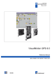
DLC-R Feed-to-Length Control with SOT Supplement
User's Manual
DOK-DIAX02-DLC1.1-DR1-02VRS-ANW1-AE-P
IAE 68003 REV. B - 06/97
This document is written for both operating personnel and the machine
builder. It explains how to interface, install, set up and operate the Indramat
DLC Positioning Control with DR software.
Revision
Date
Remarks
IAE 68003 REV. A (Firmware: DR01.1-01.0)
03/94
Initial Release
DOK-DIAX02-DLC1.1-DR1-02VRS-ANW1-AE-P
06/97
Update
INDRAMAT, 1997
Copying this document, and giving it to others and the use or communication
of the contents thereof without express authority, are forbidden. Offenders
are liable for the payment of damages. All rights are reserved in the event of
the grant of a patent or the registration of a utility model or design (DIN 341).
Validity
All rights are reserved with respect to the content of this documentation and
the availability of the product.
Published by
INDRAMAT • 5150 Prairie Stone Parkway • Hoffman Estates, IL 60192 •
Tel: (847) 645-3600 • FAX: (847) 645-6201
DLC-R Feed-to-Length Control User's Manual
Contents
Chapter 1. General Description
1-1
1.1 About this Manual................................................................................................................................. 1-4
Hardware and Software Support .................................................................................................... 1-4
1.2 How To Use This Manual ..................................................................................................................... 1-5
1.3 System Features .................................................................................................................................. 1-6
1.4 Standard Configuration Of DKS With DLC Control Card/DEA 4 Input/Output Card............................. 1-10
1.5 Brief Operational Description.............................................................................................................. 1-12
1.6 Specifications..................................................................................................................................... 1-12
Physical ....................................................................................................................................... 1-13
Control Specifications .................................................................................................................. 1-13
Interface Options ......................................................................................................................... 1-14
Chapter 2. Controls and Indicators
2-1
2.1 Data Entry Keys ................................................................................................................................... 2-1
2.2 Display Screens ................................................................................................................................... 2-3
Chapter 3. Functional Description - Standard Features
3-1
3.1 Signal Definitions ................................................................................................................................. 3-1
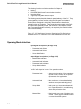
3.2 Interface Descriptions........................................................................................................................... 3-1
Operating Mode Selection.............................................................................................................. 3-2
Safety Interlock.............................................................................................................................. 3-3
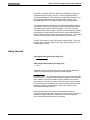
Normal Operation Signals.............................................................................................................. 3-4
Press Permissive Interface ............................................................................................................ 3-5
Jogging Inputs ............................................................................................................................. 3-12
Set up Mode ................................................................................................................................ 3-12
Fault/Diagnostic Monitoring.......................................................................................................... 3-14
3.3 Input Signal Descriptions.................................................................................................................... 3-15
Parameter Mode Select ............................................................................................................... 3-16
Automatic Mode Select................................................................................................................ 3-16
Emergency Stop .......................................................................................................................... 3-16
Cycle Start................................................................................................................................... 3-17
Resume Cycle ............................................................................................................................. 3-17
Feed Angle .................................................................................................................................. 3-17
Feed Interrupt .............................................................................................................................. 3-18
Clear............................................................................................................................................ 3-19
DOK-DIAX02-DLC1.1-DR1-02VRS-ANW1-AE-P • 06.97
Contents
I
DLC-R Feed-to-Length Control User's Manual
Jog Forward................................................................................................................................. 3-19
Jog Reverse ................................................................................................................................ 3-20
Auxiliary Feed Length Select / Measuring Wheel Enable ............................................................. 3-20
Press Continuous/Intermittent Select ........................................................................................... 3-21
Set up Mode Select ..................................................................................................................... 3-21
Cycle Stop ................................................................................................................................... 3-22
Part Stop ..................................................................................................................................... 3-22
3.4 Output Signal Descriptions ................................................................................................................. 3-23
Manual Mode Indicator ................................................................................................................ 3-24
Automatic Mode Indicator ............................................................................................................ 3-24
Parameter Mode Indicator............................................................................................................ 3-24
Cycle Time Available Indicator .................................................................................................... 3-24
Permit Press ................................................................................................................................ 3-25
System Fault Indicator ................................................................................................................. 3-26
Feed Interrupt Indicator................................................................................................................ 3-26
Feed Complete Indicator.............................................................................................................. 3-26
Feeder In Cycle ........................................................................................................................... 3-27
Feed In Progress Indicator ........................................................................................................... 3-27
Axis #1 In Position Indicator......................................................................................................... 3-28
Press Immediate Stop.................................................................................................................. 3-28
Set up Mode Indicator.................................................................................................................. 3-29
Part Early Warning Indicator ........................................................................................................ 3-29
Part Complete Indicator ............................................................................................................... 3-30
Batch Program Complete Indicator .............................................................................................. 3-30
Chapter 4. Function Description - Special Features
4-1
4.1 Batching............................................................................................................................................... 4-1
Selecting Batch Option .................................................................................................................. 4-1
Batch Entry and Status Displays .................................................................................................... 4-2
Current Part Information Display.................................................................................................... 4-2
Batch Main Programming Display Page......................................................................................... 4-3
Batch Feed Programming Display.................................................................................................. 4-5
Part Linking ................................................................................................................................... 4-6
Batching in Automatic Mode .......................................................................................................... 4-7
Batching in Set up Mode................................................................................................................ 4-8
Interface Options ........................................................................................................................... 4-8
Default Batch Program Values....................................................................................................... 4-9
4.2 RS-232/485 Serial Interface Operation ................................................................................................. 4-9
Connector Wiring (X31) ............................................................................................................... 4-11
Data Format ................................................................................................................................ 4-14
Message Format.......................................................................................................................... 4-14
Status Request (?_X_) ................................................................................................................. 4-17
Status Input ................................................................................................................................. 4-23
II
Contents
DOK-DIAX02-DLC1.1-DR1-02VRS-ANW1-AE-P • 06.97
DLC-R Feed-to-Length Control User's Manual
Batching Information.................................................................................................................... 4-24
Batching Requests....................................................................................................................... 4-24
Batching Input.............................................................................................................................. 4-27
Batching Input - Working Part and Wild Card............................................................................... 4-29
Parameter Request...................................................................................................................... 4-30
Parameter Input........................................................................................................................... 4-32
Action Requests........................................................................................................................... 4-33
Polling Request............................................................................................................................ 4-34
Checksum.................................................................................................................................... 4-35
RS-232 Flow Control.................................................................................................................... 4-35
Block Uploads.............................................................................................................................. 4-36
Serial Diagnostic Codes.............................................................................................................. 4-37
Serial Interface Errors.................................................................................................................. 4-39
SOT ScreenManager™ Notes...................................................................................................... 4-42
4.3 Measuring Wheel ............................................................................................................................... 4-43
4.4 Single Step Using Start and Stop Inputs ............................................................................................. 4-45
Chapter 5. Parameters
5-1
5.1 Parameter Set Description ................................................................................................................... 5-1
5.2 Parameter List...................................................................................................................................... 5-2
5.3 Entering the Parameters....................................................................................................................... 5-3
5.4 Unit of Measurement/Input Unit ............................................................................................................ 5-5
5.5 Parameter Set A1................................................................................................................................. 5-5
Parameter A100: Feed Length Resolution..................................................................................... 5-5
Parameter A101: Feed Constant................................................................................................... 5-7
Parameter A102: Drive Max RPM................................................................................................. 5-7
Parameter A103: Not Used ........................................................................................................... 5-8
Parameter A104: Maximum Feed Rate......................................................................................... 5-8
Parameter A105: Jog Feed Rate................................................................................................... 5-9
Parameter A106: Maximum Acceleration Rate.............................................................................. 5-9
Parameter A107: Maximum Deceleration Rate ........................................................................... 5-10
Parameter A108: Maximum Allowable Jerk................................................................................. 5-10
Parameter A109: Position Gain................................................................................................... 5-12
Parameter A110: In-Position Threshold....................................................................................... 5-13
Parameter A111: Direction of Operation ..................................................................................... 5-14
Parameter A112: Monitoring Window for Drive Diagnostics ........................................................ 5-15
Parameter A113: Low Feed Angle Threshold .............................................................................. 5-16
Parameter A114: Not Used ......................................................................................................... 5-16
5.6 Parameter Set B1............................................................................................................................... 5-17
Entering the B1 Parameter Set .................................................................................................... 5-17
Parameter B100: Language ........................................................................................................ 5-17
Parameter B101: Dimensional Units ........................................................................................... 5-18
Parameter B102: Interface Option............................................................................................... 5-18
DOK-DIAX02-DLC1.1-DR1-02VRS-ANW1-AE-P • 06.97
Contents
III
DLC-R Feed-to-Length Control User's Manual
Parameter B103: Auxiliary Feed Length...................................................................................... 5-19
Parameter B104: Feed Length Maximum Limit ........................................................................... 5-20
Parameter B105: Feed Length Minimum Limit ............................................................................ 5-20
Parameter B106: Feed Length Maximum Change During Cycle.................................................. 5-21
Parameter B107: Feed Length Micro-Adjust Increment ............................................................... 5-21
Parameter B108: Jog Step Parameter ........................................................................................ 5-22
Parameter B109: Press Interface Mode ...................................................................................... 5-22
Parameter B110: Not Used ......................................................................................................... 5-24
Parameter B111: Batching Option............................................................................................... 5-24
Parameter B112: Measuring Wheel (MW) Selection ................................................................... 5-26
Parameter B113: Not Used ......................................................................................................... 5-26
Parameter B114: Not Used ......................................................................................................... 5-26
Parameter B115: Not Used ......................................................................................................... 5-27
Parameter B116: Measuring Wheel Feed Constant..................................................................... 5-27
Parameter B117: Measuring Wheel Encoder .............................................................................. 5-27
Parameter B118: Serial Interface................................................................................................ 5-27
Parameter B119: Serial Port Operation....................................................................................... 5-28
Parameter B120: Not Used ......................................................................................................... 5-29
Parameter B121: Not Used ......................................................................................................... 5-29
Parameter B122: Slug Width Compensation ............................................................................... 5-29
5.7 Parameter Set C0 .............................................................................................................................. 5-30
Parameter C000 - Analog Output: Channel 1 ............................................................................... 5-30
Parameter C001 - Analog Output: Channel 2 ............................................................................... 5-30
Parameter C002 - Overload Factor .............................................................................................. 5-31
Parameter C003 - Position Data Scaling at Analog Outputs AK1 and AK2 ................................... 5-31
Parameter C004 - Velocity Data Scaling at Analog Outputs AK1 and AK2 ................................... 5-31
Parameter C005 - Velocity Loop Monitoring................................................................................. 5-31
Parameter C006: Not Used ......................................................................................................... 5-32
Parameter C007: Not Used ......................................................................................................... 5-32
Parameter C008 - Error Reaction................................................................................................. 5-32
Parameter C009 - Current Loop Proportional Gain....................................................................... 5-32
Parameter C010 - Velocity Loop Proportional Gain ...................................................................... 5-33
Parameter C011 - Velocity Loop Integral Reaction Time.............................................................. 5-33
Parameter C012 - Smoothing Time Constant............................................................................... 5-33
Parameter C100 - Set Standard Drive Tuning Parameters Over CTA .......................................... 5-34
Chapter 6. Installation
6-1
6.1 Mounting Cabinet ................................................................................................................................. 6-1
6.2 Power................................................................................................................................................... 6-2
6.3 Cable Routing ...................................................................................................................................... 6-2
6.4 Transformer - Heat Dissipation............................................................................................................. 6-2
6.5 Hardware Installation............................................................................................................................ 6-2
6.6 Electrical Installation ............................................................................................................................ 6-3
IV
Contents
DOK-DIAX02-DLC1.1-DR1-02VRS-ANW1-AE-P • 06.97
DLC-R Feed-to-Length Control User's Manual
6.7 DLC/DEA 4 Connectors........................................................................................................................ 6-3
Chapter 7. Start-Up
7-1
7.1 Connections ......................................................................................................................................... 7-1
7.2 DEA 4 Input Connections ..................................................................................................................... 7-1
7.3 DEA 4 Ouput Connections.................................................................................................................... 7-2
7.4 Power-up.............................................................................................................................................. 7-3
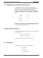
7.5 Digital AC Servo Amplifier Parameter Entry ......................................................................................... 7-4
Changing The Display Language ................................................................................................... 7-4
7.6 Main Menu ........................................................................................................................................... 7-4
Setting The Drive's Parameters To Operate With The DLC Control Card....................................... 7-5
7.7 Parameter Entry ................................................................................................................................... 7-8
7.8 Axis Jogging In Manual Mode............................................................................................................... 7-9
7.9 Automatic Operation ............................................................................................................................ 7-9
Chapter 8. Diagnostics and Troubleshooting
8-1
8.1 Digital Servo Drive Normal Operating Diagnostics ............................................................................... 8-1
8.2 Status / Diagnostic Display Alphabetical Index ..................................................................................... 8-2
8.3 Diagnostic Display Categories .............................................................................................................. 8-4
Hard Fault...................................................................................................................................... 8-4
Soft Fault....................................................................................................................................... 8-5
Minor Errors................................................................................................................................... 8-5
Status Messages............................................................................................................................ 8-6
8.4 Hard Fault Messages............................................................................................................................ 8-6
8.5 Soft Fault Messages........................................................................................................................... 8-10
8.6 Minor Error Messages ........................................................................................................................ 8-15
8.7 System Status Messages ................................................................................................................... 8-18
General Messages ....................................................................................................................... 8-18
Automatic Mode Messages .......................................................................................................... 8-19
Manual Mode Messages .............................................................................................................. 8-21
Set up Mode Messages................................................................................................................ 8-22
8.8 SOT Status / Diagnostic Codes Index................................................................................................. 8-23
8.9 IDS Status / Diagnostic Codes Index .................................................................................................. 8-25
Appendix A. Display Map
A-1
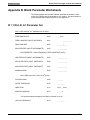
Appendix B. Blank Parameter Worksheets
B-1
B 1.1 DLC-R, A1 Parameter Set.................................................................................................................B-1
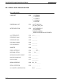
B 1.2 DLC-R B1 Parameter Set..................................................................................................................B-2
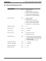
B 1.3 DLC-R C0 Parameter Set..................................................................................................................B-3
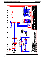
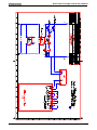
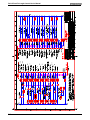
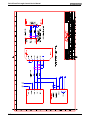
Appendix C. Schematics
DOK-DIAX02-DLC1.1-DR1-02VRS-ANW1-AE-P • 06.97
C-1
Contents
V
DLC-R Feed-to-Length Control User's Manual
Appendix D. Installation Drawings
D-1
E Index
E-1
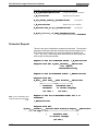
Figures
Figure 1-1: DKS/DLC-R Feed-To-Length Positioning Control System
Figure 1-2: Block Diagram
Figure 1-3: Optional Thumbwheel Switch & Alphanumeric Display Modules
Figure 1-4: SOT - Station Operator Terminal
Figure 1-5: Standard Configuration Of DKS With DLC Control Card and DEA 4 I/O card
Figure 2-1: CTA Display/Keypad Module
Figure 2-2: Map of CTA Control Panel Display Pages
Figure 3-1: Use of Feed Interrupt Input
Figure 3-2: Generation of Feed Angle Signal
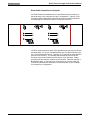
Figure 3-3: Continuous Mode - Press Before Feed
Figure 3-4: Continuous Mode - Feed Before Press
Figure 3-5: Intermittent Mode - Press Before Feed
Figure 3-6: Intermittent Mode - Feed Before Press
Figure 3-7: X17 Input/Output Connector Showing Input Pin Designations
Figure 3-8: Feed Angle Switch Layout
Figure 3-9: X17 Input/Output Connector Showing Output Pin Designations
Figure 4-1: DLC X31 Connector
Figure 4-2: Signal Level Requirements
Figure 4-3: RS-232 Serial Cable Configurations
Figure 4-4: Data Format
Table 5-1 Typical Decimal Placement
Table 5-2 Decimal Placement
Figure 5-1: Profile without Jerk Limiting
Figure 5-2: Profile with Jerk Limiting
Figure 5-3: In-Position Threshold
Figure 5-4: PBF Batch Complete = 0 (end with press cycle)
Figure 5-5: PBF Batch Complete = 1 (end with feed cycle)
Figure 7-1: Example Input Diagram
Figure A-1: DLC Display Map
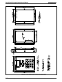
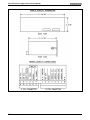
Figure D-1: CTA4 Keyboard and Cabinet Cutout Dimensions
Figure D-2: IDS Outline Drawing
Figure D-3: Vorne Display Dimensions and Connections
Figure D-4: Vorne Display DIP Switch Configuration
Figure D-5: Station Operator Terminal SOT 02 for Rollfeed
VI
Contents
1-2
1-3
1-9
1-10
1-11
2-1
2-5
3-5
3-7
3-9
3-9
3-11
3-11
3-15
3-18
3-23
4-11
4-12
4-13
4-14
5-6
5-6
5-11
5-12
5-14
5-25
5-25
7-3
A-1
D-2
D-3
D-4
D-5
D-6
DOK-DIAX02-DLC1.1-DR1-02VRS-ANW1-AE-P • 06.97
DLC-R Feed-To-Length Control User's Manual
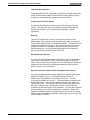
Chapter 1. General Description
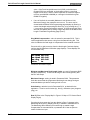
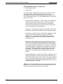
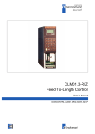
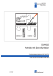
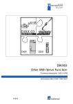
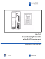
The DLC is a single axis positioning control card which plugs into the
Indramat Digital AC Servo Drives, such as the DKS (Digital Compact Servo
Drive) or DDS (Digital AC Servo Drive) products. The DKS is a selfcontained power supply and digital servo drive. The DDS is a digital servo
drive which operates with the TVD (AC Power Supply). The DLC requires a
DEA 4 Input/Output card to provide the system inputs and outputs to operate
the Digital AC Servo System. The DLC plugs into the U1 slot and the DEA 4
plugs into the U2 slot of the Indramat Digital Servo Drives. The DLC
controls and Indramat maintenance-free MDD Digital AC Servo Motor to
drive feed rolls or some other positioning device. This is a closed-loop
feedback system which provides precise control of speed and position at all
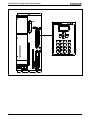
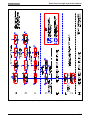
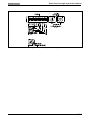
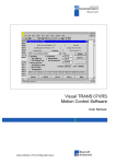
times. The DLC/DEA 4 installed in the Indramat DKS, Digital Compact AC
Servo Drive, is illustrated in Figure 1-1: DKS/DLC-R Feed-To-Length
Positioning Control System.
The DLC/servo system is used for material positioning applications. It
controls the feeding of metal, foil, film and similar materials through a shear,
punch press, bagmaking machine, thermoforming machine or similar
production machine. Complete interconnect cable sets are also available
from Indramat. The components are chosen to best fit the specific
application. Figure 1-2: Block Diagram is a block diagram of a typical
system configuration.
DOK-DIAX02-DLC1.1-DR1-02VRS-ANW1-AE-P • 06.97
General Description 1-1
DLC-R Feed-To-Length Control User's Manual
Figure 1-1: DKS/DLC-R Feed-To-Length Positioning Control System
1-2
General Description
DOK-DIAX02-DLC1.1-DR1-02VRS-ANW1-AE-P • 06.97
DLC-R Feed-To-Length Control User's Manual
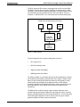
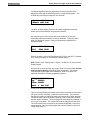
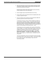
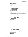
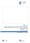
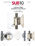
The DLC requires a DEA 4 card to be plugged into the U2 slot of the DKS.
The DEA 4 card provides 15 system inputs and 16 system outputs. Other
information, such as batch programs, parameters, and system status can be
communicated (two way) between the DLC and a host device, such as a
computer, or Indramat SOT, via a multi-format serial communications port.
OPERATOR INTERFACES (OPTIONAL)
PC
SOT
IDS
PANEL
DKS
C
T
A
DIGITAL
COMPACT
CONTROLLER
Inputs
Outputs
MDD
SERVO
MOTOR
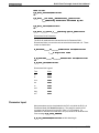
Figure 1-2: Block Diagram
The DLC Digital AC Servo System configuration consist of
∗
DLC control card
∗
DEA 4 Input/Output card,
∗
Digital Controller (DKS/DDS)
∗
MDD Digital AC Servo Motor.
The machine builder or user enters data into the DLC parameters to specify
the mechanical and operating characteristics of the system. Based on this
data, plus the feed length and feed rate entered by the operator, the DLC
issues positioning commands to the digital controller, a DKS (Digital
Compact Controller) or DDS (Digital Controller), which controls the current
driving the MDD AC Servo Motor, which drives the mechanical feed
mechanism.
The MDD AC Servo Motor includes a high resolution feedback, which
provides velocity and position feedback to the digital servo drive, ensuring
precise, repeatable positioning of the material being fed. The final accuracy
of the feed system depends on various factors, such as type of material,
gearbox backlash and other machine mechanics.
DOK-DIAX02-DLC1.1-DR1-02VRS-ANW1-AE-P • 06.97
General Description 1-3
DLC-R Feed-To-Length Control User's Manual
System components are modular, thus installation and replacement of any
component of the system is fast and easy. The Indramat Digital AC Servo
Drive and the MDD AC Servo Motor have quick-connect cabling. The drive
and MDD Servo Motor are matched for optimum operation using a plug-in
DSM module. Thus, should a failure occur, replacement of the digital drive
is accomplished quickly without the need for electronic fine tuning. This
results in a minimum of lost production.
The system is designed to ensure operating integrity and safety, using
various inputs and outputs for handshaking to assure that the feeder and
subsequent processing station or device operate in harmony. A complete
diagnostic system monitors all inputs/outputs and operating conditions and
stops the system if a fault is detected. Diagnostic messages are displayed
to aid the operator in troubleshooting problems and quickly getting the
system back into production.
1.1
About this Manual
This document is written for both operating personnel and the machine
builder. It explains how to interface, install, set up and operate the Indramat
DLC Positioning Control with DR software.
Hardware and Software Support
This manual describes the DLC1.1 hardware, used with software version
DR1-02VRS.
Indramat provides assistance for any problems you may encounter with this
system. Your first source of information should be this manual. To report a
problem or request assistance, call Indramat at [847] 645-3600, between
9:00 AM and 5:00 PM Central time. Ask for a Service Engineer. You may
also write or FAX to the following:
Rexroth-Indramat
Attn: Service Engineering
5150 Prairie Stone Parkway
Hoffman Estates, IL 60192
1-4
General Description
FAX Number: [847] 645-6201
DOK-DIAX02-DLC1.1-DR1-02VRS-ANW1-AE-P • 06.97
DLC-R Feed-To-Length Control User's Manual
1.2
How To Use This Manual
The manual is organized such that Chapters 1 and 2 describe the DLC
control and its operation. These chapters, plus Chapter 8 on diagnostics, will
be sufficient for most operating personnel. Chapters 3-8 provide functional
description, installation, set up, parameter entry, and diagnostic and
troubleshooting information required by the machine builder and set up
personnel.
Chapter 1.
General Description
Describes the DLC control and the
features which make it well suited for
motion control. Describes and
illustrates various options. Lists
specifications.
Chapter 2.
Controls & Indicators
Describes the CTA keypad and displays
interfaced with the DLC control card.
Chapter 3.
Functional Description
of Standard Features
Describes all pre-defined input and
output signals and the various
interfacing and operating modes of the
DLC. This information is necessary for
interfacing the DLC to the machine
builder's equipment, control panel
design and troubleshooting.
Chapter 4.
Functional Description
of Special Features
Provides same type of information as
Chapter 3 for enhanced features which
include: Batching, multi-format RS232/485 interface, Measuring Wheel
and Single Step using Start and Stop
Inputs.
Chapter 5.
Parameters
Describes all user-entered parameters
required to adapt the DLC to the
mechanical and electrical characteristics
of each application.
Chapter 6.
Installation
Describes procedures for installing a
DLC control system.
Chapter 7.
Start-up
DOK-DIAX02-DLC1.1-DR1-02VRS-ANW1-AE-P • 06.97
Provides an example of a DLC start-up.
General Description 1-5
DLC-R Feed-To-Length Control User's Manual
Chapter 8.
Diagnostics &
Troubleshooting
Describes the DLC's self-diagnostic
system, lists and explains all diagnostic
messages and describes
troubleshooting procedures.
Appendices
1.3
Appendix A -
Display Map (DLC display screens
which appear on the CTA control panel)
Appendix B -
Blank parameter record forms for use in
documenting your system parameters
Appendix C -
Drawings and schematics of the
DKS/DLC.
Appendix D -
Installation drawings & details for the
DLC and options: IDS Thumbwheel
Switch Panel and Remote Display
Module
Appendix E-
Index
Supplement
User's Guide for the Station Operators
Terminal (SOT), an optional operator
interface terminal for the DLC
System Features
Superior Performance and Ease of Operation
The system offers press rates up to 1200 strokes per minute and feed
resolution of 0.001 inch, which minimizes scrap and lowers cost. Note that
maximum system performance depends on the mechanical characteristics of
the user's system.
The user simply and easily operates the feed control system by entering feed
rate and feed length using front panel controls. Operating status messages
appear on the display in English, German, French or Spanish - as selected
by parameter. Other input and display options are described later in this
section. The DLC system includes features to make set up quick and easy,
eliminating time consuming mechanical set up or complex programming
when changing parts. System operation is described in detail in Chapter 3.
1-6
General Description
DOK-DIAX02-DLC1.1-DR1-02VRS-ANW1-AE-P • 06.97
DLC-R Feed-To-Length Control User's Manual
Parameter-adaptable to Multiple Machines
The feeder manufacturer or the user easily adapts the DLC to the
mechanical and electrical characteristics of an application by entering data
into a set of parameters, using the CTA 20 digit keypad and liquid crystal
display (LCD), or from a host via the serial port. These parameters define
the characteristics of the machine, such as: maximum and minimum feed
lengths, jog, acceleration and deceleration rates, units of feed measurement,
communications port characteristics, etc. This allows one single type of DLC
control to handle the mechanics of various roll feed units. Thus, plant
personnel need be familiar with only one feed control system.
Generally, parameters are entered once when the system is set up, then
changed only if the configuration changes or if different types of materials
are fed. The factory installed DLC executive program interprets the
parameters to match the DLC to the machine, and translates operatorentered commands into motion control signals, coordinating the feed motion
with the press or other machinery. Complicated system programming is not
required.
Parameters are described in Chapter 5.
Fully Self-Diagnostic
System protection is paramount. The DLC detects normal operating status,
operator errors, errors in the control itself and machine faults. For example,
in a metalforming application, the DLC monitors the press crank angle and
halts the system if the selected feed cannot be made without damaging the
press, tooling or material. If a feed is not completed during the allowable
press feed angle, a diagnostic error message is displayed and the feed and
press automatically stop. If necessary, the ram can be inched back, the
press speed can be reduced and press/feed operation can be resumed
without loss of material or damage to the tool or die. An indicator informs
the operator when the speed can be increased without causing this problem
and when the speed is set so high that it may cause the problem.
Both fault and normal status messages are displayed on the DLC control
panel (or host device via the serial port) in the user-selected language .
Thus, the operator is informed of the current operating status of the system
and is alerted to any condition that causes a fault. This helps the operator
quickly locate and correct problems.
The DLC processor models and predicts the motion profile and continuously
compares it with the actual response of the servo drive, thereby detecting
irregularities in drive conditions, such as drive runaway or stalled conditions.
Parameters allow the user to set the magnitude of certain variations, as
required for the application, before a deviation error is considered a fault
condition.
Diagnostics are described in detail in Chapter 8.
DOK-DIAX02-DLC1.1-DR1-02VRS-ANW1-AE-P • 06.97
General Description 1-7
DLC-R Feed-To-Length Control User's Manual
Jerk Limited Acceleration
Parameters allow the user to generate a jerk limited (S-shaped) acceleration
profile, which increases machine life and allows handling difficult, slippery,
compliant or delicate materials at increased production rates.
Independent Accel/Decel Ramps
Parameters allow different acceleration and deceleration rates for linear
profiles. This allows the user to most effectively accommodate differing
material characteristics, such as stretching susceptibility, in various
applications.
Batching
The user can program the control for the sequence required to make
different parts. Then, through simple keyboard entry, select the quantity of
one or several different parts to be made automatically. The program allows
multiple feed lengths for each part. It also allows branching from one part
program to another, to make different parts, and looping to continuously
make the same part. Up to 99 parts and 594 feeds can be entered and
stored in the battery protected memory of the DLC.
RS-232/485 Serial Interface
A multi-format serial interface allows communication with a programmable
logic control, a Indramat IDS or SOT, a personal computer or other host
device. Every function (and more) that can be entered with the keypad and
displayed on the LCD can be communicated between the DLC and host
device at rates of up to 19200 Baud.
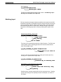
Optional Thumbwheel Switch Panel And Alphanumeric Display
An optional thumbwheel switch module (IDS) and an optional alphanumeric
display, illustrated in Figure 1-3: Optional Thumbwheel Switch &
Alphanumeric Display Modules, are available for the DLC. The IDS
connects to the serial port of the DLC. The remote display is available only
with the IDS option. These units are remotely mounted, up to fifteen (15)
meters from the DLC. The operator selects the required feed length and a
feed rate on different sets of thumbwheel switches. The decimal place
(resolution) for the feed length is set by parameter. The feed rate is selected
as a percentage of the maximum feedrate set in parameter. Status and
diagnostic messages appear on the alphanumeric vacuum tube fluorescent
display or status and diagnostic message codes appear on the two digit LED
numeric display on the IDS.
1-8
General Description
DOK-DIAX02-DLC1.1-DR1-02VRS-ANW1-AE-P • 06.97
DLC-R Feed-To-Length Control User's Manual
Figure 1-3: Optional Thumbwheel Switch & Alphanumeric Display Modules
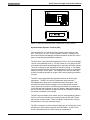
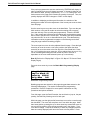
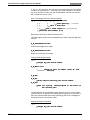
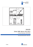
Optional Station Operator Terminal (SOT)
The Indramat SOT is a remote mounted, operator control device for the
DLC. See Figure 1-4: SOT - Station Operator Terminal. It allows for the
same input functions and displays the same information as the DLC control
panel, but provides several additional features.
The SOT has a viewing area that measures 4-7/8" by 2-3/4" and can display
16 lines of 40 characters per line. The SOT screen is a non-glare LCD with
cold cathode fluorescent lamp backlighting for high black and white contrast.
The level of contrast is user adjustable for optimum viewing. It can display
much more information at a time than the standard four line by 16 character
display on the DLC control panel. The software in the SOT provides Help
screens to assist the operator in using the SOT and for entering information
correctly.
The SOT is pre-programmed with appropriate screens for DLC-R type
applications. The SOT can also be programmed using Indramat's
ScreenManagerTM when further customized screens are desired. This
command line editor software package runs on a DOS based computer.
This program can be used to customize/write information and prompt lines
for the operator that will appear on the SOT display. When downloaded to
the SOT, these lines cannot be changed from the SOT keypad but data can
be entered in response to the prompts.
The SOT keypad includes "click contact" keys for entering/changing data in
the DLC, as well as several inputs normally provided on the user's control
panel by the machine builder. These include the mode selection, axis jog forward/reverse, and cycle start-stop-resume.
The SOT connects to the serial communications port of the DLC and can be
mounted up to 1000 meters away with an RS-485 cable. An SOT User's
Guide is provided at the end of this manual as a supplement.
DOK-DIAX02-DLC1.1-DR1-02VRS-ANW1-AE-P • 06.97
General Description 1-9
DLC-R Feed-To-Length Control User's Manual
Figure 1-4: SOT - Station Operator Terminal
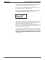
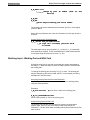
1.4
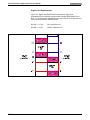
Standard Configuration Of DKS With DLC Control
Card/DEA 4 Input/Output Card
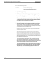
The DLC Control Card plugs into the U1 slot and the DEA 4 Input/Output
Card plugs into the U2 slot of the the Indramat Digital AC Servo Controller.
The Indramat Digital Controller being used mounts to the panel of a control
cabinet (electrical enclosure). Installation procedures are described in
Chapter 6.
1-10
General Description
DOK-DIAX02-DLC1.1-DR1-02VRS-ANW1-AE-P • 06.97
DLC-R Feed-To-Length Control User's Manual
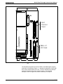
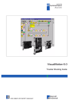
DLC
Cont rol
Card
DEA 4 . 1
I/O Card
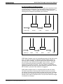
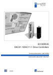
Figure 1-5: Standard Configuration Of DKS With DLC Control Card and DEA 4 I/O
card
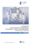
The standard configuration for the DLC/DEA 4 with DKS (Digital Compact
Controller), is illustrated in Figure 1-5: Standard Configuration Of DKS With
DLC Control Card and DEA 4 I/O card. The DLC with DEA 4 Input/Output
card has 15 system inputs and 16 system outputs. The functional
description of the I/O signal connections is described in Chapter 3.
DOK-DIAX02-DLC1.1-DR1-02VRS-ANW1-AE-P • 06.97
General Description 1-11
DLC-R Feed-To-Length Control User's Manual
1.5
Brief Operational Description
The DLC, servo amplifier, servo power supply and servomotor are designed
into a mechanical feed system, which feeds some type of material into
another processing station, such as a punch press, thermoforming station,
etc.
The machine builder or user enters data into the DLC parameters to specify
the mechanical and operating characteristics of the system. Based on this
data, plus the feed length and feed rate entered by the operator, the DLC
issues velocity commands to the servo amplifier, which controls the current
driving the servomotor, which drives the mechanical feed mechanism.
The servomotor includes a tachometer and encoder which provide velocity
and position feedback to the control, ensuring precise, repeatable positioning
of the material being fed. The final accuracy of the feed system depends on
various factors, such as type of material, gearbox backlash and other
machine mechanics.
System components are modular, thus installation and replacement of any
component of the control system is fast and easy. The DLC card, servo
amplifier and servomotor have quick-connect cabling. This results in a
minimum of lost production.
The system is designed to ensure operating integrity and safety, using
various inputs and outputs for handshaking to assure that the feeder and
subsequent processing station or device operate in harmony. A complete
diagnostic system monitors all inputs / outputs and operating conditions and
stops the system if a fault is detected. Diagnostic messages are displayed to
aid the operator in troubleshooting problems and quickly getting the system
back into production.
1.6
Specifications
The following sections provide full specifications for the DLC Control and
options.
NOTE: Performance specifications can vary, depending on the mechanical
limitations of the system.
1-12
General Description
DOK-DIAX02-DLC1.1-DR1-02VRS-ANW1-AE-P • 06.97
DLC-R Feed-To-Length Control User's Manual
Physical
Operating Environment
Cooling
Convection
Allowable Ambient
41 to 113 deg. F
Temperature Range
(5 to 45 deg. C)
Storage and Transport
-22 to 185 deg. F
Temperature Range
(-30 to 85 deg. C)
Maximum Operating
Altitude at Rated Values
3,280 ft. (1000 meters),
higher altitudes permitted
with proper cooling
Position Feedback
Indramat high resolution
single turn encoder
Feed Length Resolution
0.0001 inches (0.001 mm)
Control Specifications
Feed Rate
Normal -
0.1 - 99.9% of Maximum
Feed Rate
(Operator Selected)
Jog -
0.1 - 99.9% of Maximum
Feed Rate
(Parameter Selected)
NOTE: Maximum Feed Rate will vary, depending on the mechanical
design of the system.
Jogging
Forward/Reverse (Manual /
Set up Modes only)
Status/Fault Display
LCD, Four lines,
Alphanumeric, 16
Characters/ Line, optional
backlit version available
Entry Keypad
20 membrane switch keys
DOK-DIAX02-DLC1.1-DR1-02VRS-ANW1-AE-P • 06.97
General Description 1-13
DLC-R Feed-To-Length Control User's Manual
Power Requirements
Optional IDS Module -
50 mA @ 24 Vdc
(additional)
I/O Interface
Inputs
15 (+24 Vdc @ 10 mA)
(pre-defined function)
Outputs
16 (+24 Vdc @ up to 100
mA sourcing) (pre-defined
function)
RS-232/485
This interface allows remote
operation and other data
transfer between the DLC
and a host device, such as
a computer, programmable
controller, the IDS / Remote
Display or SOT,
IDS Module
A remote thumbwheel
switch assembly used for
Interface Options
entering feed length and
feed rate for operation;
displays status and fault
codes
Remote Display
A remote mounted, vacuum
florescent tube display
(requires the IDS option)
SOT
1-14
General Description
Station Operator Terminal Used for displaying
diagnostics, entering feed
length, feed rate, etc. It
also contains Cycle Start,
Stop, Jog, Mode, Microadjust and other control
pushbuttons.
DOK-DIAX02-DLC1.1-DR1-02VRS-ANW1-AE-P • 06.97
DLC-R Feed-To-Length Control User's Manual
Chapter 2. Controls and Indicators
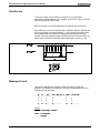
The DLC-R uses the CTA keypad and display module which consists of a
keypad with 20 pressure-sensitive membrane type keys and a liquid crystal
display (LCD) that has four lines of up to 16 alphanumeric characters each.
The display informs the operator of the operating status of the DLC system.
It displays all status and diagnostic messages. It is used when entering or
editing parameters, batch programming or other operations from the DLC
keypad.
The keypad contains all the keys used for data entry, cursor movement,
clearing fault/error messages, entering feed length and feed rate data, and
storing entries.
LIQUID CRYSTAL
DISPLAY
20 BUTTON
KEYPAD
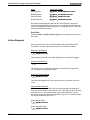
Figure 2-1: CTA Display/Keypad Module
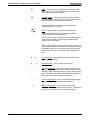
2.1
Data Entry Keys
This section describes the general function of each key on the CTA keypad.
Their use is further described throughout the manual for specific functions.
DOK-DIAX02-DLC1.1-DR1-02VRS-ANW1-AE-P • 06.97
Controls and Indicators 2-1
DLC-R Feed-To-Length Control User's Manual
CL
Clear -- Use to clear the a displayed fault message, if the
fault can be cleared. It also clears parameter entry errors.
(See Store key for additional uses.)
CR
Carriage Return -- When changing data values, press this
key before pressing the Store key to cancel the change and
leave the data as previously stored (clear entry).
In Parameter Mode, use this key to change between
parameter sets A1, A2 and B1.
Store -- Press to store (save) values entered while in
Parameter Mode or feed rate, feed length and batch
program values while in other modes.
In other modes, use to move the cursor to the home position
of the particular display. Use to toggle between certain
displays (see next section).
When on the respective display: press this key to freeze the
Total Length value for two seconds or to change state of Jog
Step Mode; press the CL key and the Store key together to
reset the Piece Count or to clear the Total Length value to
zero.
+
&
-
Plus and Minus -- Use to specify the feed length direction;
micro-adjust data fields.
0
-
9
Numerical Keys -- Use for entering data values.
←
↑
↓
ÛÛ
2-2
Controls and Indicators
→
Left and Right Arrow -- Use to move the cursor to the left or
right one position at a time when in Parameter Mode, when
editing the feed length and feed rate, or when entering batch
data. Press the key to change between display pages on the
same row of the display map (see next section).
Up and Down Arrows -- Use to scroll through display pages
(see next section), or parameters (see Chapter 5).
Blank Key (unlabeled) -- Press from any other page
displaying to cause the Status Page to display. Press before
typing-over a parameter number to change displays.
DOK-DIAX02-DLC1.1-DR1-02VRS-ANW1-AE-P • 06.97
DLC-R Feed-To-Length Control User's Manual
2.2
Display Screens
The operating mode and keyboard selections determine the resulting
display. When in Parameter Mode, data for each parameter can be viewed,
entered or edited. Refer to Chapter 5 for procedures to scroll through
parameter displays. While in Automatic, Set up or Manual Mode, display
screens show operation status messages, status of each input and output,
etc., and allows entry of feed length, feed rate, etc.
The following section describes procedures for scrolling through each of
these display screens. Refer to the "Display Map" in Figure 2-2: Map of
CTA Control Panel Display Pages, for a full illustration of the display access
procedure. The same illustration is included in Appendix A for convenience.
This section describes the basic procedures for reading this "map" to scroll
through the different display screens and describes the information on each
screen. Following sections in this manual further describe the information
provided, procedures to edit the screens data, etc. as required for a specific
function.
To allow easier description, each row of the map is labeled A, B, C, etc. In
general, use the up or down arrow keys to change to the "home" display
screen of the proceeding or following row. Use the left or right arrow keys to
scroll through the displays on each row. Screens that allow editing data
have a cursor. Use the right/left arrow key to move the cursor in the data
field and type-over data to change. Continue pressing the arrow key to
change to the next display screen on the row. Rows allow wrapping from the
last screen on the row back to the first screen. Certain displays on the same
row have alternate pages, such as Total Piece and Total Length. Use the
CR key to toggle between them. Batching display screens require the CR
key and the +/- keys for scrolling. Procedures are described below for each
screen.
The example displays shown in the following descriptions show the batching
feature (enabled by parameter). If the feature is not enabled, its respective
display pages do not appear when scrolling through the screens. Pressing
the down arrow key from a screen on row C will scroll back to row A or to the
first enabled option in row D, E, or F.
NOTES:
•
The current DLC display provides four lines with 16 character spaces on
each line. However, all screens do not require all the lines or character
spaces. For simplicity, this manual typically illustrates the example
displays at the size required for the screens data.
•
All displays illustrated in this manual use an underline character (_) to
represent the cursor.
•
The cursor must be in home position of the display to scroll up/down to
different rows.
DOK-DIAX02-DLC1.1-DR1-02VRS-ANW1-AE-P • 06.97
Controls and Indicators 2-3
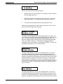
DLC-R Feed-To-Length Control User's Manual
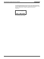
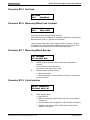
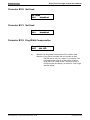
The following display appears only at power-up, when clearing a hard fault,
or when exiting from Parameter Mode. It shows the internal software version
while the "Initializing Sys" message is displayed (during system
initialization).
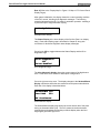
Initializing Sys
DLC1.1-DR1-02V06
DLC Initializing System Display
2-4
Controls and Indicators
DOK-DIAX02-DLC1.1-DR1-02VRS-ANW1-AE-P • 06.97
DLC-R Feed-To-Length Control User's Manual
Figure 2-2: Map of CTA Control Panel Display Pages
DOK-DIAX02-DLC1.1-DR1-02VRS-ANW1-AE-P • 06.97
Controls and Indicators 2-5
DLC-R Feed-To-Length Control User's Manual
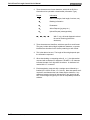
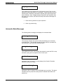
Row A (Refer to the "Display Map" in Figure 2-2: Map of CTA Control Panel
Display Pages)
After system initialization, the display shows the current operating condition
of the DLC control, including fault diagnostic messages. The following
example indicates that the DLC is ready for automatic operation - awaiting a
Cycle Start input to begin automatic cycling.
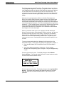
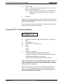
A: No Cycl Start
Example Status Display
This Status Display is the home display of the first line (Row A on display
map). Each status display page is described in Chapter 8, along with
corrections for fault/error diagnostic status display messages.
Pressing the CR key toggles between the Status Display and the Drive
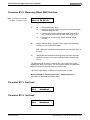
Diagnostic Page.
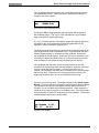
Drive Diagnostic
102
Drive Enabled
Drive Diagnostic Page
The drive diagnostic display shows the current status of the digital servo
drive. Refer to the drive manual for description of diagnostics.
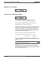
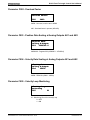
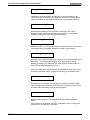
Press the right arrow key once. The display changes to the Strokes/Minute
Display, which also shows the time used and current press mode selection.
Each line of the display is described below.
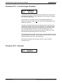
Strokes/Min 200
Time Used
80%
PBF Continuous
Strokes/Minute Display
The Strokes/Minute display page shows the current stroke rate of the press
during an Automatic Mode cycle. The DLC measures the time between
press strokes and updates the Strokes per Minute display when the feed
angle signal goes from high to low.
2-6
Controls and Indicators
DOK-DIAX02-DLC1.1-DR1-02VRS-ANW1-AE-P • 06.97
DLC-R Feed-To-Length Control User's Manual
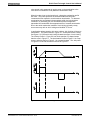
The display page also shows Time Used. Time Used is the amount of time
during a high feed angle that is used by the programmed feed. The percent
value displayed provides an estimate of the maximum press stroke rate that
can be used with the current feed length, feed rate, and feed angle. For
example, if the current hit rate is 100 strokes/min. and the time used is 75%,
the maximum hit rate would be approximately 100/0.75 = 133 strokes/min.
(SPM).
When the time used approaches 100%, the soft fault 'Feed Angle Lost
During Feed' will be issued, because the press rate is too fast and the feed
angle will go low before the feed is complete. In Press Intermittent mode,
the maximum Strokes/Minute is limited by the minimum cycle time specified
in the Press Interface Parameter. The Time Used display does not go above
99 percent. A Time Available output can be used to indicate when the stroke
rate can be safely increased without loss of the feed angle. A light can
indicate when the feed time is within 90% of the maximum hit rate allowed.
See Chapter 3 for further description.
When an Automatic mode cycle is not in progress, the last Strokes per
Minute/ Time Used values will be displayed. After a cycle stop, the data can
be read even though the press is not cycling. The page is not updated in
Manual, Set up, and Parameter modes. Hard faults, soft faults, and minor
errors also will not affect the Strokes per Minute value. At power-up, the
values are reset to zero. Pressing the Store key freezes the display for two
seconds.
The current press mode selection is displayed in the bottom line of the
Strokes/Min. display. These modes of operation are described in Chapter 3.
•
Press Interface Mode: PBF=Press Before Feed, FBP=Feed Before
Press.
•
Press Cycle Mode: Intermittent or Continuous. This is changed
whenever the corresponding input is changed. It may be changed during
a cycle.
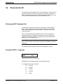
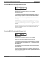
Press the right arrow key once. The display changes to the Software
Version Display. The following display shows the current hardware version
and the current internal software version.
Version Numbers
DLC1.1-R
DLC1.1-DR1-02V06
DSM 2.1-C11-03V02
Software Version Display
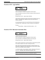
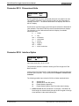
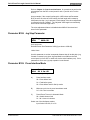
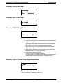
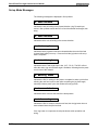
Press the right arrow key once. The display changes to the Jog Step Mode
Display. This feature allows defining the distance that the DLC will feed
when the Jog button is pressed in Manual Mode. Jog velocity is set in
parameter.
DOK-DIAX02-DLC1.1-DR1-02VRS-ANW1-AE-P • 06.97
Controls and Indicators 2-7
DLC-R Feed-To-Length Control User's Manual
Jog Step Mode
ON
Jog Step Mode Display
With normal jog (Jog Step Mode set to OFF), the DLC will feed as long as
the forward or reverse jog button is pressed, and stops when the button is
released. With Jog Step Mode set to ON, the DLC will feed a parameterdefined distance when a jog button is pressed.
To change the jog mode from Normal Jog to Step Jog, press the STORE
key while on the Jog Step Mode page. The display will indicate the Step
Mode is ON or OFF. Jog Step mode is enabled in Manual Mode only.
The DLC feeds material at jog velocity until the jog input goes low (jog
button released) or until the step length has been reached. Once the step
length is nearing completion, the motor(s) will be ramped down to zero
velocity and a 1.5 second delay occurs to provide time to release the jog
button. After the delay, another feed will start if the jog button has not been
released. If the jog button is released before the step feed has completed,
the DLC will complete the parameter set feed length.
Any time the motor is ramped down to zero velocity the Feed Complete
output will go high. If the step mode ON/OFF is toggled while the motors are
in motion, the motors will be ramped down and "Jog Input Active" will be
displayed.
Row B (Refer to the "Display Map" in Figure 2-2: Map of CTA Control Panel
Display Pages)
Pressing the down arrow key from any of the displays on the top row,
changes to the Axis Position Displays. This is the "home" display set of
the second row (Row B) of displays. Use the left or right arrow keys to scroll
through the input / output status and total piece count displays on this row.
Use the CR key to toggle between certain pages, as described below.
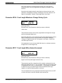
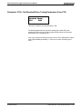
The Position Display shows either axis lag or distance moved.
The Distance Moved Display shows the distance moved by the axis during
each feed (the actual position read from the encoder).
Axis Position
Dist +00123.456
Axis Position Distance Moved Display on DLC-R
2-8
Controls and Indicators
DOK-DIAX02-DLC1.1-DR1-02VRS-ANW1-AE-P • 06.97
DLC-R Feed-To-Length Control User's Manual
The Lag Display shows the following error - the difference between actual
and commanded position - used by the DLC to calculate the command
voltage to the servo amplifier.
Axis Position
Lag
-00001.234
Axis Position Lag Display on DLC-R
Pressing the CR key toggles between the Lag Display and the Distance
Moved Display pages. The "Lag" or "Dist" indicates the Lag or Distance
page of the position display respectively.
A (+) or (-) indicates direction. Both display pages have eight (8) digits and
are shown in the unit of measurement selected by parameter for the
application (inches, millimeters, degrees, etc.).
The Distance Moved Display has the same number of decimal places as the
feed length resolution (set in Parameter A100). In Manual Mode, the total
distance jogged displays. In Automatic and Set up Modes, the distance
moved during each feed displays. At the start of a feed in Automatic or Set
up Modes, the display is cleared to zero (0). Pressing the CL key will also
clear the display to zero (when this page is showing on the display).
The Lag Display has the same number of decimal places as the feed
constant (one more decimal place than the Distance). When the axis is not
moving, a small lag value will display. In order for the axis to be "inposition," the In-Position Threshold (set in Parameter A110) must be greater
than this lag value. When the axis is moving at maximum velocity, the
display lag should be within 10% of the calculated maximum lag.
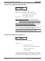
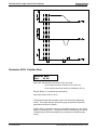
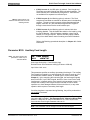
Press the right arrow key once. The display changes to the System Inputs
Display. Press the right arrow key again to see the System Outputs Display.
The numbers in the top row of the display indicates which of the lines of
connector X17 of the DEA4 card are being monitored. These displays are
helpful to verify wiring during start up or troubleshooting. They also provide
a quick summary of system I/O status during normal operation. The first line
of these displays also show the system status.
A: No Cycl Start
Sys Inputs 1-15
.11..1....11.11
System Inputs Display
DOK-DIAX02-DLC1.1-DR1-02VRS-ANW1-AE-P • 06.97
Controls and Indicators 2-9
DLC-R Feed-To-Length Control User's Manual
The status of each of the input or output signal lines are represented by a
character in the bottom row of the display. A Low signal (0 volts) is
represented by a decimal (.). A High signal (+24 volts) is indicated by a one
(1). The signal lines count from left to right on the display.
Press the right arrow key to see the System Outputs Display. Interpret the
information displayed the same as described for inputs.
A: No Cycl Start
Sys Outputs 1-16
..1.11...1..1...
System Outputs Display
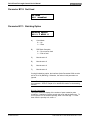
Press the right arrow key to see the Total Piececount Display.
Total Piececount
000123
Total Piececount Display
Press the CR key to toggle between Total Piececount Display and the Total
Length Display.
Total Length
+1234567.890
Total Length Display
The total number of pieces and length of material run through the feeder are
displayed on these Length and Piece Accumulator Displays. These totals
may be reset at any time.
The piece count is incremented when one full cycle of the press is completed
in the Automatic mode or after each part is completed when batching mode
is selected. Normally, 6 digits are displayed, but up to 8 can be shown as
they are needed. The count is retained in memory at power-down.
To reset the counter to zero:
1. Press the CL key. The count display is replaced by a prompt.
Total Piececount
RESET DATA?
2-10
Controls and Indicators
DOK-DIAX02-DLC1.1-DR1-02VRS-ANW1-AE-P • 06.97
DLC-R Feed-To-Length Control User's Manual
2. If you wish to reset the counter to zero, press the STORE key to clear
the count. The added step of pressing the STORE key prevents the
count from being reset inadvertently.
3. If you do not wish to reset the counter to zero, press any other key or
leave the page. This action will restore the original count.
Note: The Total Length value is
generated from the motor encoder
and not from the Measuring
Wheel function.
The Total Length Display is accessed by pressing the CR key while in the
Total Piececount display. The length is accumulated in Automatic mode
only, and includes all batching and auxiliary feed lengths. The DLC displays
from 6 to 10 digits of data with a floating decimal point. The display may be
frozen for 2 seconds by pressing the STORE key. The total length is
retained in memory at power-down.
To clear the length, press the CL key, then the STORE key, as described in
the steps above for the Total Piececount.
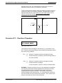
Row C (Refer to the "Display Map" in Figure 2-2: Map of CTA Control Panel
Display Pages)
Pressing the down arrow key from any display in the B row changes to the
Feed Length Display, the home display of the C row. Other displays on
this row show relevant parameter settings. The parameter data display
pages are for information only. Parameter data can be edited/changed only
in Parameter Mode.
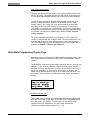
The feed length display allows entering the feed length and feed rate desired
for system operation. The display looks and functions differently, depending
on the interface option set in Parameter B102. This parameter selects the
method of entering the feed length and feed rate into the DLC.
Feed Length and Feed Rate on a DLC with Standard Interface Option
The standard option setting allows entering/editing the feed length and feed
rate directly from the keypad on the DLC control panel. Use the left/right
arrow keys to position the cursor on the data line. Type over an existing
entry to edit. Press the STORE key to save the new value. The cursor
returns to home position.
Current Feed:
Length
Rate
_001.234 12.2%
Feed Length and Feed Rate Display - Standard Interface, DLC-R
To scroll up or down to the previous or next row of displays from this display
page, note that the cursor must be in the home position. It automatically
returns to home after storing new data. Press the CR key or use the left/right
arrow keys to properly position. Micro-adjust (explained later in this section)
is allowed only when the cursor is in home or the first digit position.
DOK-DIAX02-DLC1.1-DR1-02VRS-ANW1-AE-P • 06.97
Controls and Indicators 2-11
DLC-R Feed-To-Length Control User's Manual
When changing the feed length or feed rate value while the DLC is in cycle
(on-the-fly), this new value typically takes effect on the next cycle. If you
press the CR key, or leave the keyboard inactive for 30 seconds before
pressing the STORE key, the cursor returns to home position and the
program (and display) returns to the last stored information (data).
The decimal placement in the feed length depends on the setting in
Parameter A100. The feed rate is a percentage of the Maximum Feed Rate
set in Parameter A104.
If you press the CR key, or leave the keyboard inactive for 30 seconds
before pressing the STORE key, the cursor returns to home position and the
program (and display) returns to the last stored information (data).
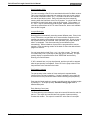
Feed Length and Feed Rate on a DLC with the IDS Interface Option
When using the IDS option, the feed length and feed rate are entered into
the DLC using the IDS thumb-wheel switches. This display shows IDS in the
first line, indicating the option is selected. It does not contain a cursor or
allow editing from the keypad. The display is only for information of the
settings made through the IDS (connected to the RS-232 connector of the
DLC). The display shows the last data entry processed after a two second
delay from when the thumb-wheel switch is changed. If the serial port
transmits an invalid character, a (*) will display instead of a digit (or digits).
Enter the settings again, check connections, etc., until the display data is
valid.
IDS Feed
Length Rate
001.234 12%
Feed Length and Feed Rate Display - DLC-R, with the IDS Interface Option
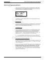
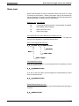
Feed Length and Feed Rate on a DLC with the Batching Option
Enabled
The batching option allows setting multiple feed lengths and feed rates for
each part and up to 99 different parts. The Current Part feed length display
on Row C shows information for the current feed of the part currently
executing or ready to be executed.
Procedures for entering/changing data (feed lengths, feed rates, etc.) for the
batching option are described in this section under Rows G and H.
Current Feed
Length
Rate
+001.234 12.2%
Feed Length and Feed Rate Display - DLC-R with Batching Option Selected
2-12
Controls and Indicators
DOK-DIAX02-DLC1.1-DR1-02VRS-ANW1-AE-P • 06.97
DLC-R Feed-To-Length Control User's Manual
No cursor appears on this display for the DLC-R. However, micro-adjust
(described later in this section) is allowed.
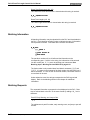
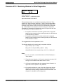
Additional Information Pages on Row C
From the DLC feed length / feed rate display, you can view additional
information pages. These show settings made in different parameters. You
cannot edit the parameter values from these pages. They are for
information only.
Press the left (or right) arrow key from the feed length / feed rate display,
until the desired Parameter Information page displays. The following
summarizes the lines of information on these displays. Refer to Chapter 5
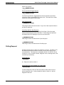
for further information on parameter entries.
Aux Fd -010.000
Jog Step 000.500
Fd Incr. 000.050
Slug Cmp 000.650
Parameter Information Display
Auxiliary Feed Length - is a secondary feed length - entered in Parameter
B103. Use an external switch to trigger the DLC to use this feed length
instead of the standard one entered.
Jog Step - setting is entered in Parameter B108. This function is enabled/
disabled from a display on Row A. In Manual Mode, pressing a jog key will
cause the DLC to feed the length entered in the parameter, then stop (if the
function is enabled, as further described under Row A).
Feed Length "micro-adjust" Increment - is set in Parameter B107. It
allows you to fine tune (micro-adjust) the programmed feed length by adding
or subtracting the value entered in the parameter.
To use this micro-adjust feature
•
Press the arrow keys to display the main feed length / feed rate page
(home display of this row). Simply pressing the (+) or (-) key on the
keyboard adds or subtracts the increment to or from the previously
programmed feed length and automatically stores the new value. The
micro-adjust feature works from this display page for both the standard
DLC and batching interface options, and on the Batch Feed
Programming display (row G), and other pages as noted.
•
A (+) key will add the value entered in Parameter B107 to the
programmed feed length and store the new value. If the Feed Length
Maximum Limit (B104) or the Maximum Change (B106) are exceeded, a
minor error is issued. A (-) key will subtract the value entered in
Parameter B107 from the programmed feed length and store the new
DOK-DIAX02-DLC1.1-DR1-02VRS-ANW1-AE-P • 06.97
Controls and Indicators 2-13
DLC-R Feed-To-Length Control User's Manual
value. If the Feed Length Minimum Limit (B105) or the Maximum
Change (B106) are exceeded, or the change results in a zero feed
length, a minor error is issued. Micro-adjust will not cause the digits to
roll-over (past 000000 to 999999) or a change in feed direction (past
000000 to negative).
•
If one of the limits is exceeded (Maximum Limit, Minimum Limit,
Maximum Change), the respective error occurs. The error may be
cleared while the Batch Feed Programming page displays by entering a
correct feed length and pressing the Store key, or by pressing the (+), or
(-) keys until a correct feed length is entered. A Feed Length Limit minor
error can be cleared also by storing a legal value while in the Batch Feed
Length / Feed Rate Programming page (Row F).
Slug Width Compensation - value is entered in parameter B122. This is
used in applications that remove a slug from the material being fed. This
value is added to the feed length to compensate for the material removed.
Press the left (or right) arrow key from the feed length / feed rate display,
until the desired Parameter Information page displays. These displays are
for information only.
Min Feed
Max Feed
Max Chg.
Units
000.500
100.000
010.000
in.
Parameter Information Display
Minimum and Maximum Feed Length Limits - are set in Parameters B105
and B104 respectively. These limit the range of the feed length entry that
the DLC will accept.
Maximum Change - setting is made in Parameter B106. This parameter
limits the amount that the programmed feed length can change during an
Automatic Mode cycle before causing a fault to occur.
Units Setting - selection is set in Parameter B101, as desired for the
application. It can be set for inches (in), feet (ft), millimeters (mm), degrees
(deg), etc.
Row D (Refer to the "Display Map" in Figure 2-2: Map of CTA Control Panel
Display Pages)
Pressing the down arrow key from any display in Row C, changes to the
Measuring Wheel (M.W.) Display (Row D), if enabled in Parameter B112.
The Measuring Wheel Select input must be high to enable Length
Compensation in Automatic Mode, or parameter B112 has an option to
enable it without an input.
2-14
Controls and Indicators
DOK-DIAX02-DLC1.1-DR1-02VRS-ANW1-AE-P • 06.97
DLC-R Feed-To-Length Control User's Manual
The Measuring Wheel position page shows the current position of the
measuring wheel and the Axis being used for Length Compensation. The
STORE key will freeze the display for two seconds.
Axis 1 +001.234
M.Wheel +001.240
M.W. Position Display
The M.W. position display is active in all modes regardless of the M.W.
Select input so that deviation can always be checked.
Pressing the right or left arrow key will cause display of the axis and
measuring wheel feed constants, as set by parameter. These are useful
when fine-tuning the system. Editing of parameters is allowed only in
Parameter Mode.
A101
B116
0001.0000
0001.0020
M.W. Parameter Display
Refer to Chapter 4, and to the Parameters B112, B116, and B117 in Chapter
5 for further information on the Measuring Wheel feature.
Row F (Refer to the "Display Map" in Figure 2-2: Map of CTA Control Panel
Display Pages)
Press the down arrow key from any page in Row C to see the Batch Current
Part Information Display (if Batching option is selected). This section
overviews the display pages used in batching. Refer to Chapter 4 for
additional information on batch programming options.
INFO_01 11111111
Qty
000100
Count 000001
Feed 1 Cnt 001
Current Part Information Display
This is a real-time display that shows most current information for the current
part (part currently executing or selected to execute next). The part block
and part ID number will change as each part executes in the batch program.
The part quantity and count show the quantity of the current part to execute
and the number executed. The count mode can be selected in parameter to
count up or count down. The current feed number changes with each feed.
The current feed count increments or decrements, depending on the count
mode selected. The current feed length and feed rate display on the Feed
Length page (Row C).
DOK-DIAX02-DLC1.1-DR1-02VRS-ANW1-AE-P • 06.97
Controls and Indicators 2-15
DLC-R Feed-To-Length Control User's Manual
If the part is programmed to execute continuously, FREERUN will display in
place of quantity and count will always increment. If the part is linked to use
more than six feeds, quantity is replaced by "++++++" or "Linking Part" until
feeds execute to the page which includes the quantity for the part. Then, the
quantity displays and "INFO" changes to "LINK" on this display.
In addition to displaying real-time part information, the selection of the
starting part number and micro-adjustment of the current part count are done
from this page.
Use the arrow keys to move the cursor in the data fields. Type over the part
block number or the part ID number to select the starting part to execute
(can start with any of the up to 99 parts programmed). Press the STORE
key. If the current part is selected as the starting part, the batching program
will be reset to the start of the current part. The starting part entry is allowed
only when the DLC is not in an Automatic Mode cycle. Note that batching
information must be programmed into pages on the following rows before
using this page to start the batching program.
The current part count can be micro-adjusted from this page. Press the right
arrow key to move the cursor out of home position, then press the down
arrow key to move the cursor to the first digit of the Count data field. Press
the + key to add to the count; press the - key to subtract from the count. Key
use for increasing/decreasing the total number of parts to execute is
dependent on the count mode selected (count up or count down).
Row G (Refer to the "Display Map" in Figure 2-2: Map of CTA Control Panel
Display Pages)
Press the down arrow key to see the Batch Main Programming Display
page.
Main_01 11111111
Jump to Block 02
Quantity 000010
Early Warn
002
Batch Main Programming Display
Batching programs are entered on this page using part data entered on the
following related pages. This section summarizes the programming
procedures. Refer to Chapter 4 for more specific information on entry
procedures and options available.
From this page, enter the Part ID number, the next block to jump to, the part
quantity, and the Early Warning count for each part.
Within the page, use the right and left arrow keys to move the cursor through
the data fields. The cursor will wrap from row to row within the page. Other
than home position, pressing the up or down arrow keys causes the cursor to
move to the first position of the next or preceding row in the display. Type
over data to change. Press the STORE key to save any changes (saves all
data as currently displayed) and return the cursor to home position. Press
2-16
Controls and Indicators
DOK-DIAX02-DLC1.1-DR1-02VRS-ANW1-AE-P • 06.97
DLC-R Feed-To-Length Control User's Manual
the CR key before pressing STORE to clear any changes to data (reverts to
data previously saved) and return the cursor to home position.
Press the + / - keys to scroll through batch main programming pages and
enter information for each part, numbers 01 to 99.
Press the CR key to toggle between the Batch Main Programming page and
the Batch Feed Programming Display page for each part.
Part_01 11111111
Feed 1 Cnt 001
Length Rate
+012.345 67.8
Batch Feed Programming Display
There can be up to six Batch Feed Programming pages associated with each
Batch Main Programming page. From these pages, enter data for up to six
feeds per part, including feed quantity, length, and rate.
Press the + / - keys to scroll through feed programming pages (with the
cursor next to "Feed" in the display) and view/enter information for each feed
required for the part (feed 1 up to feed 6).
Enter data for part 01 on the main programming page. Press CR and enter
data for the first feed required for part 01. Press +, enter data for the second
feed for part 01, etc. Return to the main programming page. Press +, enter
data for part 02. Press CR and enter data for the first feed required for part
02. Press + and enter data for each feed required for part 02. Continue this
process for each part
DOK-DIAX02-DLC1.1-DR1-02VRS-ANW1-AE-P • 06.97
Controls and Indicators 2-17
DLC-R Feed-To-Length Control User's Manual
Chapter 3. Functional Description - Standard Features
Several input / output signals of the DLC control provide communication with
the other components of the machine. This chapter describes the functional
operation of the interfacing inputs and outputs of the DLC.
The first sections of this chapter describe the various interface functions in
terms of the inputs / outputs involved with each. This section is followed by
an individual description of each pre-defined I/O signal, including name, pin
assignments, and functional description. The machine designer utilizes
these signals as necessary to implement the DLC for his application,
including the design of his system control panel. Also refer to the appendix
for example system wiring of these and other optional signals.
3.1
Signal Definitions
The states of the input and output signals described in this manual are:
High = +24 Vdc
Low =
0 Vdc
A signal line is described as "active high" when its associated action is
initiated by a high (+24 Vdc) signal level. It is described as "active low"
when its function is initiated by a low signal (0 volts). This chapter describes
the function with the active state of each I/O connection.
3.2
Interface Descriptions
The DLC interfaces with a feed device of some type. The DLC system is
designed for control of a continuous indexing process, such as a press
feeder. The DLC input and output signals provide communication to/from
the machine builder's equipment, and should be considered as functional
groups of signals, working in concert. These functions include:
•
Operating Mode Selection
•
Servo System Operation Enables
•
Safety Interlocks
•
Normal Operation Signals
•
Handshaking, or Press (or Processing Station) Permissive Interface
•
Jogging Inputs
•
Set up Mode
•
Fault/Diagnostic Circuitry
DOK-DIAX02-DLC1.1-DR1-02VRS-ANW1-AE-P • 06.97
Functional Description - Standard Features 3-1
DLC-R Feed-To-Length Control User's Manual
The following functions are further described in Chapter 4.
•
•
•
•
Batching
RS-232/485 Multi-format Communications Interface
Measuring Wheel
Single Step Using Start and Stop Inputs
The following sections describe the basic operation theory of the DLC. They
group signals by interface function, listing the I/O signals involved (and
section where each signal is individually described), then describe the
general function of the signals. These signal descriptions apply to the DLCR except where specifically noted. Later sections in this chapter describe
the I/O connections/signals individually, as required by the machine builder
and for troubleshooting.
Figure 3-7: X17 Input/Output Connector Showing Input Pin Designations
illustrates the X17 I/O connector and the signal designation for each pin.
Operating Mode Selection
Input Signal Descriptions (See Page 3-15)
•
Parameter Mode Select
•
Automatic Mode Select
•
Set up Mode Select
Output Signal Descriptions (See Page 3-23)
•
Manual Mode Indicator
•
Automatic Mode Indicator
•
Parameter Mode Indicator
•
Set up Mode Indicator
The DLC will always be in one of four operating modes:
3-2
Functional Description - Standard Features
Parameter Mode
- Allows entry/verification of the parameters
required to set the control for the specific
requirements of the application.
Automatic Mode
- Either continuous or intermittent feeding
operations occur (automatically cycles).
Set up Mode
- Used to set up for the automatic material
feed. Especially useful in a metalforming
system with progressive dies.
Manual Mode
- Default mode when none of the above are
selected. Used to jog the material forward
or reverse through the system.
DOK-DIAX02-DLC1.1-DR1-02VRS-ANW1-AE-P • 06.97
DLC-R Feed-To-Length Control User's Manual
Parameter, Automatic and Set up Modes are selected by bringing the
appropriate signal line high (+24 Vdc). A fault is diagnosed and an
"Invalid Mode Selection" error message is issued if both Automatic and
Set up Mode signal lines are high simultaneously. However, the
Parameter Mode input overrides any other mode presently selected.
The suggested interface design is to wire the Parameter Mode signal to
a key-switch, where a key is required to enter Parameter Mode, and/or
mount the switch inside the electrical cabinet. This helps to prevent
unauthorized parameter changes. Wire the Automatic and Set up Mode
input signals to a three-position selector switch, where Manual Mode is
selected when the switch is set to an open contact position. This method
prevents selecting Automatic and Set up Mode at the same time.
The DLC has outputs to verify the currently selected mode. These are
typically wired to indicator lights on the user's control panel (or to a PLC
for total system control).
Safety Interlock
Input Signal Descriptions (See Page 3-15)
•
Emergency Stop
Output Signal Descriptions (See Page 3-23)
•
NA
As described above, the DLC and its servo must perform operational
checks and provide the proper signals to enable operation.
Emergency Stop -- The Emergency Stop input must remain high for the
DLC to operate. The system incorporates an Emergency Stop (E-Stop)
chain, which is a circuit connected in series to both the DLC and the
user's machine. Should any sensor in the E-stop chain open, all press
and feed operations immediately stop. Note that the time taken to stop
depends on the wiring method used, inertia of the machine, press
clutch/brake retaining circuit, etc.
Elements connected in the E-stop chain commonly include the
Emergency Stop switch on the user's control panel; E-stop switch(es) on
the press or feeder; switches on lubrication or coolant pumps; and
various die guards and safety interlock switches.
DOK-DIAX02-DLC1.1-DR1-02VRS-ANW1-AE-P • 06.97
Functional Description - Standard Features 3-3
DLC-R Feed-To-Length Control User's Manual
Normal Operation Signals
Input Signal Descriptions (See Page 3-15)
•
Cycle Start
•
Cycle Stop
•
Feed Interrupt
Output Signal Descriptions (See Page 3-23)
•
Feed In Progress Indicator
•
Feed Complete Indicator
•
Axis #1 In Position Indicator
•
Feed Interrupt Indicator
The automatic feed cycle begins when the Cycle Start line goes high
(momentary) with the DLC in Automatic Mode. Once the automatic feed
cycle begins, it is normally stopped by a Cycle Stop input (line goes low,
momentary). Feed will stop after completing the current cycle. The
system will also stop if a fault is detected, either immediately, as an
Emergency Stop, or after the cycle, as a Cycle Stop, depending on the
level of the fault.
In Automatic Mode, a Single Step can be performed by activating the
Cycle Stop + Cycle Start simultaneously. The DLC will step one feed
and one press stroke. With batching enabled, activating Part Stop +
Cycle Start simultaneously causes the DLC to perform the feeds and
press strokes for one part.
Several outputs are issued by the DLC during normal system operation.
They include:
•
Feed in Progress Indicator - Indicates that a feed is in progress and
the feed axis is not within the position threshold specified in
parameter A110.
•
Feed Complete Indicator - Indicates that the commanded feed is
complete and the axis is within the position threshold.
•
Axis In Position Indicator(s) - Indicates that the feed axis has
stopped within the position threshold specified in Parameter A110.
A feed interrupt can occur as a normal part of an automatic cycle. A
high on the Feed Interrupt input indicates normal operation. If this signal
goes low, the feed cycle is interrupted, the Feed Interrupt Indicator
output goes high and an appropriate status message appears in the
display. When the signal is restored high, the feed cycle immediately
resumes.
3-4
Functional Description - Standard Features
DOK-DIAX02-DLC1.1-DR1-02VRS-ANW1-AE-P • 06.97
DLC-R Feed-To-Length Control User's Manual
Figure 3-1: Use of Feed Interrupt Input
This signal is often used in conjunction with a material loop, as illustrated
in Figure 3-1: Use of Feed Interrupt Input. Material is fed through a
leveler or straightener into a looping pit, with an optical sensor in the pit
tied to the feed interrupt line. If the material pulls too tight, Feed
Interrupt goes low and the feed cycle is interrupted. As soon as an
adequate amount of material is fed into the looping pit, the signal returns
high and the feed cycle immediately resumes.
Warning: If the automatic cycle is interrupted by a low on the Feed
Interrupt line, all feed motion is suspended. Once this signal is restored
high, the feed cycle will immediately resume. Personnel should use
extreme caution when entering the work area if the feed has stopped as
a result of this signal.
Normally a Feed Interrupt is of short duration, so it only stops the feed
momentarily; it does not stop the press (ram) operation. Should the feed
remain interrupted too long, the Feed Angle input from the press will
drop (before the feed cycle is completed) and the system will be halted
with a diagnostic error message displayed.
Press Permissive Interface
Note that the following description refers to the operation of a press and
press feeder. These descriptions are equally valid for a feed system
with other types of processing station, such as a seal-shear station or a
thermoforming station.
Input Signal Descriptions (See Page 3-15)
•
Feed Angle
•
Press Continuous/Intermittent Select
DOK-DIAX02-DLC1.1-DR1-02VRS-ANW1-AE-P • 06.97
Functional Description - Standard Features 3-5
DLC-R Feed-To-Length Control User's Manual
Output Signal Descriptions (See Page 3-23)
•
Press Immediate Stop
•
Permit Press
The control system is designed such that feeder operation can occur
only when a series of permissive conditions are true. This is
accomplished by a group of handshaking inputs/outputs between the
DLC and the press interface. They are described below in the general
order of occurrence.
•
Press Continuous/Intermittent - Input from the user's control panel
which selects the press operating mode. Continuous specifies
continuous press cycling, synchronized with the material feed.
Intermittent specifies that the press will be cycled one time at the
end of, or just previous to each feed cycle.
•
Cycle Start - Momentary input signal from the user's control panel
that starts the automatic feed cycle see Normal Operation Signals.
•
Permit Press - Output from DLC used to permit engagement of the
press clutch (if all other safety logic circuitry on the press is
satisfied). This output allows press operation differently when
Continuous or Intermittent mode is selected, as described in the
following sections.
•
Feed Angle - Input, generally from a limit switch or sensor on the
press or processing station, indicating that material can safely be
fed. For a punch press this signal would come up shortly after the
ram clears the material on its upstroke. See Figure 3-2: Generation
of Feed Angle Signal. The signal would drop (go low) on the ram
downstroke, allowing some safety margin before the ram reaches
the material. The material feed must have stopped before this
signal drops or the feed will stop immediately and an error will
display.
•
Press Immediate Stop - Output from the DLC, issued when a Feed
Angle Lost During Feed! or other various faults are detected. See
Press Immediate Stop, page 3-28 for details. This signal commands
the user's circuitry to stop the press (or other machine) as soon as
mechanically possible, rather than stopping after the current cycle is
complete (as with a Cycle Stop).
Warning: The Press Immediate Stop signal must be incorporated into
the safety logic circuitry of the machine. Note that safety design of the
system is the responsibility of the machine tool builder.
3-6
Functional Description - Standard Features
DOK-DIAX02-DLC1.1-DR1-02VRS-ANW1-AE-P • 06.97
DLC-R Feed-To-Length Control User's Manual
Figure 3-2: Generation of Feed Angle Signal
Press Continuous Operation
Conditions:
Automatic Mode input high
Press Continuous/Intermittent input high
1. Cycle Start input (momentary) goes high.
2. DLC issues the Permit Press output at the appropriate point and
maintains it until the automatic cycle ends. Permit Press should be used
by the press system to engage the press clutch for automatic cycling - IF
all other press safety logic circuitry is satisfied.
Parameter B109 allows selecting one of two continuous modes, Press
Before Feed or Feed Before Press. Figure 3-3: Continuous Mode Press Before Feed and Figure 3-4: Continuous Mode - Feed Before
Press are timing charts which illustrate these operations.
DOK-DIAX02-DLC1.1-DR1-02VRS-ANW1-AE-P • 06.97
Functional Description - Standard Features 3-7
DLC-R Feed-To-Length Control User's Manual
3. When the Feed Angle input from the user interface goes high, the DLC
commands the servos to operate, feeding material to the length and at
the feed rate specified by the operator.
During the cycle, the DLC issues various outputs, which are normally
wired to indicators on the user's control panel.
a. Feed In Progress output is issued while the feed is occurring.
b. Feed Complete output is issued when the feed is complete and the axis
is within the position threshold.
c.
Axis #1 In Position output is issued once the axis has arrived within the
parameter-specified in-position threshold window.
If Feed Angle is lost during a feed, the DLC decelerates the feeder to a
stop and issues a diagnostic message. This typically indicates that the
press cycle is too fast. It does not allow sufficient time for a complete
feed to occur between when the ram leaves the material on its upstroke
(Feed Angle goes high - feed begins) and when the ram approaches the
material on its downstroke (Feed Angle drops low - is lost).
If Feed Angle is lost, or the automatic cycle is ended, the Permit Press
output is dropped. The machine builder typically employs a press clutch
engagement retaining circuit that retains clutch engagement until the
press ram reaches Top Dead Center and is stopped. The timing for
stopping the press depends on whether Press Before Feed or Feed
Before Press is selected. See Figure 3-3: Continuous Mode - Press
Before Feed and Figure 3-4: Continuous Mode - Feed Before Press for
timing details.
The Press Immediate Stop output is also dropped low when Feed Angle
is lost during a feed or various faults are detected. If this signal from the
DLC is wired to the press, it should attempt to stop as soon as
mechanically possible.
3-8
Functional Description - Standard Features
DOK-DIAX02-DLC1.1-DR1-02VRS-ANW1-AE-P • 06.97
DLC-R Feed-To-Length Control User's Manual
Figure 3-3: Continuous Mode - Press Before Feed
Figure 3-4: Continuous Mode - Feed Before Press
DOK-DIAX02-DLC1.1-DR1-02VRS-ANW1-AE-P • 06.97
Functional Description - Standard Features 3-9
DLC-R Feed-To-Length Control User's Manual
Press Intermittent Operation
Conditions:
Automatic Mode input high
Press Continuous/Intermittent input low
1. Cycle Start input goes high.
2. The DLC issues the Permit Press output to initiate engagement of the
press clutch on a per cycle basis. The Permit Press signal is dropped
when the Feed Angle goes low.
The system typically operates as described below. Refer to Figure 3-5:
Intermittent Mode - Press Before Feed and Figure 3-6: Intermittent Mode
- Feed Before Press for timing charts which further explain intermittent
Press Before Feed and Feed Before Press Modes.
3. When the Feed Angle input from the press goes high, the next feed
movement is initiated. At the completion of the feed, the Permit Press
output is issued, if and only if the Minimum Cycle Time has elapsed.
These actions occur at the appropriate time, depending on the selection
of Press Before Feed or Feed Before Press.
During the cycle, the DLC issues various outputs, as described under
continuous operation above.
When Feed Angle goes low, Permit Press output is also pulled low.
Because of the press clutch retaining circuitry that most press builders
employ, the press completes one cycle. The press clutch engagement
retaining circuit releases the clutch and sets the brake such that the ram
stops at Top Dead Center (TDC). The press then waits (dwells) until the
DLC initiates the next press cycle.
The minimum amount of dwell time at TDC is controlled by the time
value entered in Parameter B109. If the minimum cycle time is less
than the sum of the press cycle time plus the feed time, the Permit Press
will be issued immediately (output high) at the end of the feed.
The Press Immediate Stop output is also pulled low when Feed Angle is
lost during a feed, or other various faults occur. See Press Immediate
Stop Page 3-28. If the user has wired this signal to his press, it will
attempt to stop as soon as mechanically possible.
3-10
Functional Description - Standard Features
DOK-DIAX02-DLC1.1-DR1-02VRS-ANW1-AE-P • 06.97
DLC-R Feed-To-Length Control User's Manual
Figure 3-5: Intermittent Mode - Press Before Feed
T=Minimum cycle time specified by Parameter B109 when the press is in intermittent operation. S=Stroke
* T is longer than the cycle time needed by the press and feed sequence, therefore it limits the stroke rate.
Figure 3-6: Intermittent Mode - Feed Before Press
T=Minimum cycle time specified by Parameter B109 when the press is in intermittent operation. S=Stroke
* T is shorter than the cycle time needed by the press and feed sequence, therefore it has no effect on the stroke rate.
DOK-DIAX02-DLC1.1-DR1-02VRS-ANW1-AE-P • 06.97
Functional Description - Standard Features 3-11
DLC-R Feed-To-Length Control User's Manual
Jogging Inputs
Input Signal Descriptions (See Page 3-15)
•
Axis 1 Jog Forward
•
Axis 1 Jog Reverse
Output Signal Descriptions (See Page 3-23)
•
NA
The DLC's Jog inputs allow jogging the material forward and reverse.
Parameter A105 specifies the jog feed rate. It usually is set to
approximately 10% of the maximum feed rate. It can never be more
than the maximum feed rate.
In Manual Mode, a high on the Jog Forward (Reverse) input causes the
axis to feed forward (reverse) at the velocity set in Parameter A105, as
long as the respective jog input is high. If Jog Step is set ON (from DLC
control panel display), the DLC feeds material at the jog velocity until the
jog input goes low (jog button released) or the step length (set in
Parameter B108) has been reached.
The Jog inputs are not functional in Parameter or Automatic Modes.
The effect of these inputs in Set up Mode is described in the following
section.
Set up Mode
Set up Mode is normally used to jog the material through the feeder for
set up in progressive die applications. A progressive die application has
multiple stations. A series of feeds and press strokes, moves the
material through multiple stations in a single die to produce a finished
part.
It is often necessary to manually thread the leading edge of the material
through the die to set up the operation. In order to avoid damaging
expensive dies during set up, in most cases it is critical to cycle the
press only after a full feed has been made for each progression. The
press must be cycled, before the feed for the next progression can
occur.
The DLC Set up Mode ensures this sequence. It allows the user to set
up his feeder by running several progressive feeds (using the jog inputs)
and manually cycling the press after each feed.
When Set up Mode is selected, the jog inputs function differently than in
Manual Mode. As in Manual Mode, a high on the Jog Forward input
causes the axis to feed forward at the parameter-specified jog velocity.
However, unlike Manual Mode, no matter how long the Jog Forward is
maintained, the axis will feed only the feed length entered on the DLC
control panel, then stop. If Jog Forward is released before the feed is
3-12
Functional Description - Standard Features
DOK-DIAX02-DLC1.1-DR1-02VRS-ANW1-AE-P • 06.97
DLC-R Feed-To-Length Control User's Manual
complete, the feed will again continue (until feed length is complete)
when Jog Forward is pressed again.
The DLC will allow the press to be manually cycled only when the userselected feed length is complete. See notes below. Another feed will
not be allowed until the press has cycled (DLC sees Feed Angle drop,
then return). Once this occurs, the jogging process described above can
be repeated (after changing the feed length entry, when required) until
the material has been threaded through all stations in the die.
Note that an error will be detected if Set up Mode is exited prior to
completing the feed and cycling the press. However, selecting Set up
Mode again clears the error and allows completion of the set up
operation.
In Set up Mode, if the Jog Reverse signal is high, the axis feeds in
reverse at the parameter-specified jog velocity. However, Jog Reverse
will only function if the feeder had previously been jogged forward, and
the reverse jog can only be as far back as the starting point of the feed.
If the feeder is already at the beginning of a feed length, reverse feed in
Set up Mode is not possible.
NOTES:
•
The Set up Mode is sensitive to Press Before Feed (PBF) and Feed
Before Press (FBP) Interface Modes.
•
When using FBP, the first action required is for the axis to be fed the
commanded length. The sequence is completed by the press being
cycled manually.
•
When using PBF, the first action required is the press being cycled
manually, followed by the axis being fed the commanded length.
•
The Permit Press output will be turned ON at the appropriate point in
the cycle, depending on the Press Interface Mode selected (PBF or
FBP).
•
If batching is enabled, Set up Mode can only use the current feed
length. For multiple feed lengths, set up can be simulated by using
Single Step (Cycle Stop + Cycle Start) in Automatic Mode, although
this causes an automatic press cycle, not manually cycled.
DOK-DIAX02-DLC1.1-DR1-02VRS-ANW1-AE-P • 06.97
Functional Description - Standard Features 3-13
DLC-R Feed-To-Length Control User's Manual
Fault/Diagnostic Monitoring
Input Signal Descriptions (See Page 3-15)
•
Resume Cycle
•
Clear
Output Signal Descriptions (See Page 3-23)
•
System Fault Indicator
The DLC includes extensive diagnostic monitoring circuitry, detecting
normal operating status, operator errors, errors in the control itself and
machine faults.
There are several categories of faults, as described in Chapter 8. In
general, once a fault is detected, an error message is displayed on the
DLC display and the feeder and press are halted (either immediately or
after the cycle is complete - depending on the type of fault).
The fault recovery procedure is to first troubleshoot and remedy the
problem. Then, press the Clear key (or external Clear input) to clear the
DLC fault status and diagnostic message on the display.
For a Soft Fault or Minor Error, a momentary high on the Resume Cycle
input will continue Automatic Mode cycling. For a Hard Fault, the
system must be restarted.
Diagnostics and fault troubleshooting procedures are described in
Chapter 8.
3-14
Functional Description - Standard Features
DOK-DIAX02-DLC1.1-DR1-02VRS-ANW1-AE-P • 06.97
DLC-R Feed-To-Length Control User's Manual
3.3
Input Signal Descriptions
This section describes the Inputs to the DLC control from external sources.
The connector and pin numbers of these signals are described in the
following sections and shown in Figure 3-7: X17 Input/Output Connector
Showing Input Pin Designations.
Each section indicates the connector and pin number, the general function of
the input signal, and the results when the signal level is in the active state,
high and/or low.
Figure 3-7: X17 Input/Output Connector Showing Input Pin Designations
DOK-DIAX02-DLC1.1-DR1-02VRS-ANW1-AE-P • 06.97
Functional Description - Standard Features 3-15
DLC-R Feed-To-Length Control User's Manual
Parameter Mode Select
Connector
-
X17, pin 1
Function
-
(Input) Selects Parameter Mode
=
Parameter Mode selected.
High
The Parameter Mode Select overrides any other mode selection input.
Selecting Parameter Mode while either Automatic or Set up Mode is
already selected, does not cause an error. When Parameter Mode is de
selected, the DLC returns to the previously selected mode - Automatic,
Set up, or Manual (default when no other modes are selected).
Automatic Mode Select
Connector
-
X17, pin 2
Function
-
(Input) Selects Automatic Mode
=
Automatic Mode selected (Parameter Mode can
override selection).
Connector
-
X17, pin 3
Function
-
(Input) Commands Motor Drive to immediate stop
High
=
Allows the DLC to operate.
Low
=
The motor drive is commanded immediately to zero
velocity. Drive reaches zero speed in the minimum
time possible - given the inertia and maximum torque
available. The DLC issues an "Emergency Stop"
diagnostic message.
High
Emergency Stop
WARNING: This signal must be used to ensure safety.
Conditions which warrant pressing the E-Stop include:
3-16
•
Any condition posing an immediate danger to personnel.
•
A jam in the machinery or any other condition that poses an
immediate harm to the system equipment.
Functional Description - Standard Features
DOK-DIAX02-DLC1.1-DR1-02VRS-ANW1-AE-P • 06.97
DLC-R Feed-To-Length Control User's Manual
Cycle Start
Connector
-
X17, pin 4
Function
-
(Input) Starts automatic feed cycle
=
(momentary) Starts the automatic feed cycle when the
DLC is in the Automatic Mode.
High
This input is typically wired to a normally open push-button switch on the
user control panel.
Resume Cycle
Connector
-
X17, pin 5
Function
-
(Input) Used to resume the automatic cycle after a soft
fault or minor error is cleared (refer to section 3.3.8)
=
(momentary) Causes the automatic cycle to resume
from its point of interruption.
High
This input is typically wired to a normally open (momentary) push-button
switch on the user control panel.
Feed Angle
Connector
-
X17, pin 6
Function
-
(Input) Controls the DLC feed cycle. See Normal
Operation Signals.
High
=
Indicates that material can be fed safely. When this
signal goes high in Automatic Mode, it initiates the
next feed cycle.
Low
=
Indicates that material cannot be fed. In a metal
forming application, a low signal indicates the press
ram is into or too close to the material to allow
feeding.
In a metal forming application, after the press leaves the material on its
upstroke, a switch or sensor is activated. See Figure 3-8: Feed Angle
Switch Layout. This switch provides a high signal to the DLC during the
rotation angles that the ram is clear of the material and it is permissible
to feed.
DOK-DIAX02-DLC1.1-DR1-02VRS-ANW1-AE-P • 06.97
Functional Description - Standard Features 3-17
DLC-R Feed-To-Length Control User's Manual
If Feed Angle goes low during a feed, the DLC issues the Press
Immediate Stop output in an effort to avoid processing an incorrectly fed
length. The soft fault diagnostic message "Feed Angle Lost During
Feed" is issued. This fault typically indicates that the press cycle is too
fast. It does not allow sufficient time for the feed cycle to complete
before the ram is too close to the material to allow feeding.
If the material slips out of the position window (set in Parameter A113 as
the Low FA Threshold) after/while the Feed Angle is low, the soft fault
diagnostic message "Movement While FA is Low" is issued.
This input is typically wired to a limit switch or sensor on the press. See
Figure 3-8: Feed Angle Switch Layout.
Figure 3-8: Feed Angle Switch Layout
Feed Interrupt
3-18
Connector
-
X17, pin 7
Function
-
(Input) Used to interrupt the feed cycle
High
=
Indicates normal operation. If not using this function,
this signal line must remain high for the DLC to
operate.
Low
=
Loss of a high signal interrupts the feed cycle (feed
decelerates). The DLC displays a "Stop Due to
Interrupt Input" diagnostic message and turns on the
Feed Interrupt Indicator output. Once the signal is
restored, the feed cycle resumes automatically in
Automatic Mode. In Manual or Set up Modes, jogging
is interrupted. When restored, jogging will resume if
commanded.
Functional Description - Standard Features
DOK-DIAX02-DLC1.1-DR1-02VRS-ANW1-AE-P • 06.97
DLC-R Feed-To-Length Control User's Manual
This input is typically wired to a normally closed switch or optical sensor
for material loop detection. If a feed interrupt occurs, it typically means
you should slow the system so it is not tugging material (causing loss of
loop/tight loop), or you should increase the speed of the uncoiler.
WARNING: If the automatic cycle is interrupted by a low (0 Vdc) on the
Feed Interrupt line, all feed motion is suspended. Once this signal is
restored (+24 Vdc), the feed cycle will immediately resume. Personnel
should use extreme caution when entering the work area if the feed has
stopped as a result of this signal.
It is recommend to use the Feed Interrupt Indicator output to advise
operating personnel when this condition exists.
Clear
Connector
-
X17, pin 8
Function
-
(Input) Clears the Hard or Soft Fault status of the DLC
=
(momentary) - Clears the Soft Fault status of the DLC,
or Clears the Hard Fault status and re-initializes the
DLC.
High
Once a fault occurs, the DLC displays a diagnostic message (refer to
Chapter 8).
The operator must then physically correct the problem. Next, the
operator must press the Clear button to clear the diagnostic message.
For a soft fault or minor error, press Resume to restart operation in
Automatic Mode (message "Resume Req'd" on display). With a hard
fault, the system must now be restarted.
This signal is typically wired to a normally open push-button switch on
the user control panel.
Jog Forward
Connector
-
X17, pin 9
Function
-
(Input) Jogs axis 1 forward
=
In Manual Mode, the axis feeds forward at the velocity
set in Parameter A105. The axis will feed forward as
long as the high signal is present (switch held closed).
With Jog Step set ON (from DLC control panel), the
axis will feed forward until reaching the feed length set
in parameter B108.
High
This input is typically wired to a normally open push-button switch on the
user control panel.
DOK-DIAX02-DLC1.1-DR1-02VRS-ANW1-AE-P • 06.97
Functional Description - Standard Features 3-19
DLC-R Feed-To-Length Control User's Manual
High
=
In Set up Mode, the axis feeds forward at the velocity
set in Parameter A105. The axis will only feed
forward the current commanded feed length, then
stop.
Connector
-
X17, pin 10
Function
-
(Input) Jogs axis 1 in the reverse direction
High
=
In Manual Mode, the axis feeds in the reverse
direction at the velocity set in Parameter. The axis
will feed in reverse as long as the high signal is
present (switch held closed). With Jog Step set ON
(from DLC control panel), the axis will feed in reverse
until reaching the feed length set in Parameter B108.
High
=
In Set up Mode, the axis feeds in the reverse direction
(if it was jogged forward previously) at the velocity set
in Parameter A105. In Set up Mode, Jog Reverse
only functions if the feeder has been jogged forward
previously. The axis can be jogged back only as far
as the starting point of the feed. If the feeder is
already at the starting point, reverse feed is not
possible.
Jog Reverse
This input is typically wired to a normally open push-button switch on the
user control panel.
Auxiliary Feed Length Select / Measuring Wheel Enable
Connector
-
X17, pin 11
Function
-
(Input) Used to enable/disable Auxiliary Feed Length
or Measuring Wheel (MW) operation depending on
the selected setting of Parameter B112.
=
=
Enables the selected option.
Disables the selected option.
High
Low
Note: See Chapter 5. Parameters
for more information on Parameter
B112.
The Auxiliary Feed Length option can only be selected in Automatic
Mode. When this option is selected, the primary feed length value is
ignored and the DLC operates using the feed length value entered in
Parameter B103.
This option allows selection of a feed length different from that used in
normal operation. It can be used to feed scrap material from the end of
the roll, to easily change to a second operation that requires a different
feed length, etc.
The Measuring Wheel (MW) feature is used to base the feed length on
the measuring wheel encoder rather than the axis position (servo
encoder). If this input is toggled during an Automatic Mode cycle, MW
3-20
Functional Description - Standard Features
DOK-DIAX02-DLC1.1-DR1-02VRS-ANW1-AE-P • 06.97
DLC-R Feed-To-Length Control User's Manual
length compensation won’t be enabled or disabled. The state of the
input is only read at Cycle Start or Resume Cycle.
Press Continuous/Intermittent Select
Connector
-
X17, pin 12
Function
-
(Input) Used to select press operating mode.
High
=
Selects continuous operation.
Low
=
Selects intermittent operation.
During Continuous Mode operation, the press stroke is continuous.
When the press ram is on the upstroke, away from the material (Feed
Angle goes high), the DLC feeds. The feed should finish before the
press ram nears the material on its down stroke (Feed Angle goes low).
This operation continues in either Press Before Feed or Feed Before
Press Modes until a Cycle Stop is issued (or a fault or error occurs).
During Intermittent Mode operation, the DLC issues a Permit Press
output signal, the press clutch engages and the stroke begins. When the
press ram nears the material on its down stroke, the Feed Angle goes
low and the DLC drops the Permit Press output. The press clutch
retaining circuit (normally employed) keeps the press operating one
cycle. When the press ram is on the upstroke, away from the material
(Feed Angle goes high), the DLC feeds. At the end of the feed, and the
end of the dwell time (need both conditions), the DLC again issues the
Permit Press to start the next cycle. This operation continues in either
Press Before Feed or Feed Before Press Modes until a Cycle Stop is
issued (or a fault or error occurs).
The press cycle mode may be changed on-the-fly using this input, at any
time during an automatic mode cycle.
See Press Permissive Interface, page 3-5 for a description of
handshaking using this and other DLC I/O signals.
Set up Mode Select
Connector
-
X17, pin 13
Function
-
(Input) Selects Set up Mode
=
Set up Mode selected (Parameter Mode can override
selection).
High
See Set up Mode, page 3-12 for description of operation in this mode.
DOK-DIAX02-DLC1.1-DR1-02VRS-ANW1-AE-P • 06.97
Functional Description - Standard Features 3-21
DLC-R Feed-To-Length Control User's Manual
Cycle Stop
Connector
-
X17, pin 14
Function
-
(Input) Used to stop the automatic cycle
High
=
(Continuous) Allows Automatic Mode operation.
Low
=
(Momentary) Stops Automatic Mode cycling at the
completion of the current cycle.
The ending point of the automatic cycle depends on the selection
entered in Parameter B109 (Press Before Feed or Feed Before Press).
See Press Permissive Interface, page 3-5.
This input is typically wired to a normally closed push-button switch on
the user control panel.
Part Stop
Connector
-
X17, pin 15
Function
-
(Input) Used to stop Automatic Mode cycling, after
completing the current
part (only functional when using the batching feature)
High
=
Indicates normal operation, allows continued batching
operation.
Low
=
Loss of a high causes the DLC to stop automatically
cycling, after all feeds are complete for the current
part executing.
This input is typically wired to a normally closed, momentary switch.
Refer to Chapter 4 for additional information on the batching function.
3-22
Functional Description - Standard Features
DOK-DIAX02-DLC1.1-DR1-02VRS-ANW1-AE-P • 06.97
DLC-R Feed-To-Length Control User's Manual
3.4
Output Signal Descriptions
This section describes the outputs from the DLC control system to external
devices. The connector and pin numbers of these signals are described in
the following sections and shown in Figure 3-9: X17 Input/Output Connector
Showing Output Pin Designations.
Figure 3-9: X17 Input/Output Connector Showing Output Pin Designations
DOK-DIAX02-DLC1.1-DR1-02VRS-ANW1-AE-P • 06.97
Functional Description - Standard Features 3-23
DLC-R Feed-To-Length Control User's Manual
Manual Mode Indicator
Connector
-
X17, pin 16
Function
-
(Output) Indicates that Manual Mode is active
=
No other modes are selected. The DLC defaults to
Manual Mode.
High
This output signal is typically wired to an indicator light on the user
control panel.
Automatic Mode Indicator
Connector
-
X17, pin 17
Function
-
(Output) Indicates that Automatic Mode is active
=
Automatic Mode is selected.
High
This output signal is typically wired to an indicator light on the user
control panel.
Parameter Mode Indicator
Connector
-
X17, pin 18
Function
-
(Output) Indicates that Parameter Mode is active
=
Parameter Mode is selected. This overrides any other
mode selection.
High
This output signal is typically wired to an indicator light on the user
control panel.
Cycle Time Available Indicator
Connector
-
X17, pin 19
Function
-
(Output) Used to indicate when the stroke rate can be
safely increased
High
3-24
Functional Description - Standard Features
=
Indicates the time used by the feed is less than 90% of
cycle time available.
DOK-DIAX02-DLC1.1-DR1-02VRS-ANW1-AE-P • 06.97
DLC-R Feed-To-Length Control User's Manual
Low
=
Indicates the time used by the feed exceeds 90%, or
when not in Automatic Mode cycle or before the first
cycle time measurement.
A light can be used as a visual indication to the operator that the press
stroke rate can be increased without causing loss of feed angle, which
would cause a fault. If the light is OFF during a cycle, the stroke rate
(time for each press stroke) should be increased or the feed rate
decreased to assure the feed completes before the feed angle input
goes low.
Permit Press
Connector
-
X17, pin 20
Function
-
(Output) Used to permit engagement of the press
clutch.
High
Low
=
=
Permits clutch engagement for press cycle operation.
Disengages the clutch and press operation halts.
Permit Press is issued when the control is ready to begin cycling. In
continuous Mode, it remains high during the automatic cycling. It goes
low if the control sees a fault or error, or a Cycle Stop is issued. In
Intermittent Mode, Permit Press is issued after the feed cycle is
complete (or before the feed cycle in Press Before Feed Mode) and
dropped during the actual feed cycle.
The timing of this signal stopping the press depends on the four possible
mode combinations. See Press Permissive Interfacefor a complete
discussion of this signal (and other I/O's) in the Press Permissive
interface. See the timing charts (Figure 3-3, Figure 3-4, Figure 3-5 and
Figure 3-6) for specific timing of this signal.
WARNING: The machine builder should tie this signal into the other
"Safety Logic Circuitry" for the press system. Do Not use this signal to
fire the press without regard for other safety conditions (interlocks open,
machine E-Stop, etc.).
The following is a list of faults which will cause the Permit Press signal to
go low causing the press cycle to stop:
All Hard Faults
All Soft Faults
Note: See Chapter 8 for more
specific information on faults.
Minor Errors:
DOK-DIAX02-DLC1.1-DR1-02VRS-ANW1-AE-P • 06.97
Zero % Feedrate Entered
Zero Feed Length Entered
Change in Feedlength Exceeds Limit
Feedlength Exceeds Maximum
Feedlength Less than Minimum
Functional Description - Standard Features 3-25
DLC-R Feed-To-Length Control User's Manual
System Fault Indicator
Connector
-
X17, pin 21
Function
-
(Output) Indicates a fault has occurred
High
=
The DLC has detected a fault.
Low
=
The system is functioning properly, or the DLC is
experiencing a power loss or its microprocessor is
defective.
This output is typically wired to an indicator light on the user control
panel.
NOTE: Any Hard Fault, Soft Fault or Minor Error will turn on this output.
See Chapter 8 for a description of faults.
Feed Interrupt Indicator
Connector
-
X17, pin 22
Function
-
(Output) Used to indicate an interrupted feed cycle
High
=
Indicates the DLC has lost the Feed Interrupt input
signal and drive motion is decelerating or stopped.
See Feed Interrupt, page 3-18.
Low
=
Indicates the DLC has not lost the Feed Interrupt
signal.
Typically, this output is wired to an indicator light on the user control
panel.
WARNING: If the automatic cycle is interrupted by a low on the Feed
Interrupt input, all feed motion is suspended. However, when the input
returns high, the feed cycle will immediately resume. Use this output to
alert personnel of the condition so they can use proper caution.
Feed Complete Indicator
Connector
-
X17, pin 23
Function
-
(Output) Used to indicate commanded feed is
complete
3-26
Functional Description - Standard Features
DOK-DIAX02-DLC1.1-DR1-02VRS-ANW1-AE-P • 06.97
DLC-R Feed-To-Length Control User's Manual
High
=
Indicates the axis is in position (within the In-Position
Threshold set in Parameter A110) and the
commanded feed is complete.
Low
=
Indicates that a feed is commanded, but is not
presently complete.
Typically, this output is wired to an indicator light on the user control
panel.
Feeder In Cycle
Connector
-
X17, pin 24
Function
-
(Output) Used to indicate Automatic feed cycle
operation
High
=
Indicates Automatic feed cycle operation is in
progress.
Low
=
Indicates a Cycle Stop, a fualt/error condition is
present, or the Feed Interrupt signal is not present (is
low).
This signal is issued (high) only in Automatic Mode, after Cycle Start. It
remains in this state until the Cycle Stop is activated or a fault or error is
detected.
Feed In Progress Indicator
Connector
-
X17, pin 25
Function
-
(Output) Used for feed progress status
High
=
Indicates feeding is in progress or the feed axis is
not in position as specified in Parameter A110.
Low
=
Indicates feeding has stopped as a result of reaching
position or a fault/error exists which has stopped the
feed.
This signal is operational in Automatic, Set up, or Manual Modes.
Typically, this output is wired to an indicator light on the user control
panel.
DOK-DIAX02-DLC1.1-DR1-02VRS-ANW1-AE-P • 06.97
Functional Description - Standard Features 3-27
DLC-R Feed-To-Length Control User's Manual
Axis #1 In Position Indicator
Connector
-
X17, pin 26
Function
-
(Output) Used to indicate axis 1 is in position
High
=
Indicates the axis is in position (within the In-Position
Threshold set in Parameter A110).
Low
=
Indicates the axis is not in position (not within the InPosition Threshold).
Typically, this output is wired to an indicator light on the user control
panel.
Press Immediate Stop
Connector
-
X17, pin 27
Function
-
(Output) Used to immediately stop the press
High
=
The normal state during operation. Wire so this signal
must be high for the press to operate.
Low
=
Immediately stops the press stroke.
NOTE: Due to various factors, such as inertia and press stroke speed,
the ram will not be able to stop instantaneously. However, if wired as
described in this section, the DLC will attempt to stop the press ram as
soon as mechanically possible if an Emergency Stop or other various
faults occur.
This signal goes low at the occurrence of the following faults (refer to
Chapter 8 for fault descriptions):
All Hard Faults
Soft Faults:
Feed Angle Lost During Feed
Movement While Feed Angle Low
Press Cycle Without Feed
Zero % Feedrate Programmed
Press Timeout has Expired
Minor Error:
Feed Angle is Missing
3-28
Functional Description - Standard Features
DOK-DIAX02-DLC1.1-DR1-02VRS-ANW1-AE-P • 06.97
DLC-R Feed-To-Length Control User's Manual
This output signal is wired to the machine builder's press engagement
clutch/brake retaining circuitry.
Upon receiving a Cycle Stop signal, the press engagement clutch/brake
retaining circuit is designed to retain clutch engagement until the press
returns to the Top Dead Center position.
However, with the Press Immediate Stop signal wired to the clutch
retaining circuit, when this signal goes low, the press attempts to stop the
ram regardless of where it may be in the press stroke.
WARNING: The Press Immediate Stop signal must be incorporated into
the safety logic circuitry of the machine. Note that safety design of the
system is the responsibility of the machine tool builder.
Set up Mode Indicator
Connector
-
X17, pin 28
Function
-
(Output) Indicates the Set up Mode is active
=
Indicates the Set up Mode is selected.
High
This output signal is typically wired to an indicator light on the user
control panel.
Part Early Warning Indicator
Connector
-
X17, pin 29
Function
-
(Output) Used in batching to indicate when this part
run is nearing completion
High
=
Indicates the batch has the user specified number of
this part (or less) remaining to be executed.
Low
=
Indicates the part count has not reached the user
specified number of parts remaining, or the entry is set
to 0, disabling the output.
When using the batching function, the user enters this "Early Warning"
number on a page of the DLC display. See Chapter 2, Display Screens.
The output turns ON when the "parts remaining" count reaches this
number. It remains ON as the remaining parts are completed. It turns
OFF when the next part begins to execute. Refer to Chapter 4 for
further information on the batching feature.
DOK-DIAX02-DLC1.1-DR1-02VRS-ANW1-AE-P • 06.97
Functional Description - Standard Features 3-29
DLC-R Feed-To-Length Control User's Manual
Part Complete Indicator
Connector
-
X17, pin 30
Function
-
(Output) Used in batching to indicate all feeds are
complete for a single part
High
=
(Momentary) Indicates a single part just completed.
Remains high about two seconds, then returns low.
When using the batching function, this output pulses momentarily as
each part completes execution, whether executing a single part or
several different parts in the Batching Program. It remains ON when the
Batching Program Complete output turns ON, and remains ON until the
next cycle start. Refer to Chapter 4 for further information on the
batching feature.
Batch Program Complete Indicator
Connector
-
X17, pin 31
Function
-
(Output) Used in batching to indicate the batching
program is completed
High
=
Indicates all parts in the batching program are
completed.
When using the batching function, this output turns ON at the end of a
batching program (when the last part is programmed with a jump to 00).
It remains ON until the next cycle start. Refer to Chapter 4 for further
information on the batching feature.
3-30
Functional Description - Standard Features
DOK-DIAX02-DLC1.1-DR1-02VRS-ANW1-AE-P • 06.97
DLC-R Feed-To-Length Control User's Manual
Chapter 4. Function Description - Special Features
This chapter describes special features available, and provides the general
information required to use these features.
4.1
•
Batching
•
RS-232/485 Interface
•
Measuring Wheel
•
Single Step Using Start and Stop Inputs
Batching
If the application requires making different parts, use batching to reduce the
set up time and eliminate possible entry errors by entering the required data
for each part into a separate batch memory. The batching option allows
multiple feed lengths for each part. It allows program branching to
automatically execute different parts.
The DLC can store up to 99 different parts, each with unique set of feed
lengths, feed rate, number of pieces to execute, and a user's part number.
Up to 594 Feeds can be stored in the DLC'S battery-protected memory.
You can select to sequentially execute several or all different parts, or to
execute any single part from the DLC control panel. You can externally
select a part to execute from an SOT, a PLC or similar host device, through
the communications port to the DLC.
The DLC display can show a running piece count display, user part number
assignment plus outputs to indicate when the part is nearing completion,
when each part is complete and when all parts in the batch run are complete.
All information assigned in batching can be viewed and edited in any mode,
even while the press is in operation. Automatic Mode, however, is the only
mode in which parts are counted as they are made.
Selecting Batch Option
Parameter B102 (interface option) allows you to select the method of
entering the feed length and feed rate into the DLC. With the "batching"
interface option selected, you typically enter the data for each part ahead of
time. Then, simply select the part or batch of different parts to execute
automatically, from the DLC keypad, or from an SOT or other host (via the
serial interface). Note that you cannot use the IDS option with the batching
option.
DOK-DIAX02-DLC1.1-DR1-02VRS-ANW1-AE-P • 06.97
Function Description - Special Features 4-1
DLC-R Feed-To-Length Control User's Manual
Batch Entry and Status Displays
Section 2.2 describes the procedures for scrolling through the display
screens, movement of the cursor within the display page and how to enter
data into fields. The following sections further describe the entry procedures
and options for batch programming.
Current Part Information Display
The Current Part Information Page has three functions: 1) select the starting
part number, 2) micro-adjust the current part count, 3) display real-time part
information. Before using this page to start the batching program, the part
information must be programmed on the other batching pages, as described
in the following sections.
INFO nn iiiiiiii
Qty
qqqqqq
Count cccccc
Feed f Cnt xxx
Current Part Information Page
Starting Part Selection
Before starting automatic operation, enter a starting part of the batch on this
page. A batching program may start with any of the 99 parts. This allows
the storage of several batching programs, each having a unique starting part
and set of parts to execute automatically.
Select the starting part by either the part block number (nn) or part ID (iiiiiiii).
To avoid an accidental part change, starting part entry is allowed only when
the DLC is not in an Automatic Mode cycle.
With the desired part number showing on the page, press the STORE key to
select it as the starting part. If the current part is entered as the starting part,
the batching program will be reset to the start of the current part by pressing
the STORE key.
Micro-adjustment of Current Part Count
Move the cursor into the first digit of the current part count (cccccc) for an
on-line adjustment of this count. Press the '+' key to add a part to the count.
Press the '-' key to subtract a part from the count.
4-2
Function Description - Special Features
DOK-DIAX02-DLC1.1-DR1-02VRS-ANW1-AE-P • 06.97
DLC-R Feed-To-Length Control User's Manual
Real-Time Part Information
This page provides a real-time display of the current part information while
the DLC is cycling. The displayed part block and Part ID will change as the
current part changes (begins executing the next part in the batch program).
The part quantity (qqqqqq) is displayed along with the current part count
(cccccc), to show the quantity of parts to be produced and the current
number of parts. The current part count will be increased or decreased
depending on the count mode selected in Parameter B111 (count up or
count down). If a part is a free run (described in next section), "FREERUN"
is displayed in the part quantity and the counter counts up, regardless of the
count mode. A linked part is indicated with a different display. See Part
Linking, page 4-6.
The current feed data is displayed in the bottom row. The current feed
number (f) changes with each change in feed. The current feed count (xxx)
is shown, and counts up or down according to the count mode parameter.
The current feed length and rate are displayed in the Feed Length Page, as
described in Chapter 2. Controls and Indicators.
Batch Main Programming Display Page
Batching programs are entered in the Batch Main Programming Page. Data
fields for a part may be accessed by typing either the Part Block or Part ID
number.
The Batch Main Programming Page allows branching, free run, or single part
operation. A part quantity is entered to set the number of times the part is
executed. An Early Warning count is provided to turn ON an output when a
part is near completion. If more than six feed lengths are desired, part
blocks may be linked together to add up to six feeds per linked block. You
can create a single part with up to 594 different feed lengths and one part
quantity.
Main nn iiiiiiii
Jump to Block pp
Quantity qqqqqq
Early Warn
eee
Batch Main Programming Page
Part Block Number (nn)
This number, from 01 through 99, is associated with feed and gagging data
for a part. The display of part block and its data can be changed by typingover with another part number. The information on the display will be
updated as the keys are pressed. The part number may also be
incremented or decremented using the '+' or '-' key.
DOK-DIAX02-DLC1.1-DR1-02VRS-ANW1-AE-P • 06.97
Function Description - Special Features 4-3
DLC-R Feed-To-Length Control User's Manual
Part ID Number (iiiiiiii)
The user can assign a Part ID to be associated with each Part Block number.
This is any eight digit number that has meaning to the user (a part number,
die number, customer number, etc.). It is stored in the DLC as a matched
set with the part block number. Each part's data may be accessed by
entering either the Part Block or the Part ID number. A unique Part ID must
be selected for each block when using the DLC keypad. The numbers 1 to
9,'+' and '-' may be entered through the keypad. Alpha characters may be
used when entered from an SOT or other host device, but are not available
from the DLC keypad.
Jump to Block (pp)
Batching allows automatically executing several different parts. Enter in the
Jump To Block the next part block to be executed after completion of the
entered part quantity of the starting or previous part block. A jump to any of
the 99 part blocks can be executed. Each part block can jump to another
after it is completed. This allows executing several different parts
automatically. Different batches of parts can be programmed to execute
together. Enter the starting number of the batch to select the desired batch
program to execute.
If a part jumps back to itself (if pp = nn), it is a free run part. The part will
run continuously until a cycle stop or part stop input is activated. The part
quantity display is replaced with the word "FREERUN" and the Early
Warning count with all stars.
If "00" is entered here, no jump is performed, and the cycle will be stopped
after the part quantity is completed. Enter "00" for the jump to block in the
last part block to be executed in the batch.
Part Quantity (qqqqqq)
The part quantity is the number of times each part is repeated before
jumping to the next part or stopping. If a zero is entered in every digit, the
current count for the part will be cleared without affecting the part quantity.
Parts may be linked together to create a part with more than six feed lengths
by entering a '+' in the part quantity. See Part Linking, page 4-6 for a
detailed description.
Early Warning Count (eee)
The Early Warning count allows an output to be turned ON near the end of a
part run. The output is turned ON when the number of parts remaining
reaches this number. The output is turned OFF at the start of a new part.
4-4
Function Description - Special Features
DOK-DIAX02-DLC1.1-DR1-02VRS-ANW1-AE-P • 06.97
DLC-R Feed-To-Length Control User's Manual
Batch Feed Programming Display
There are six Feed Programming Pages associated with each Batch Main
Programming Page. Feed lengths, rates, and gag sets may be edited for
each feed, which may be executed up to 999 times.
Part nn iiiiiiii
Feed f Qty xxx
Length
Rate
+mll.lll rr.r
Batch Feed Programming Page
The displayed Part Block Number and Part ID are being programmed by
entries on this page.
Feed Number (f)
The feeds are executed in order from 1 to 6 within each part. Data fields for
feeds 1 to 6 can be accessed sequentially by pressing the '+' and '-' keys or
access a feed directly by typing-over the number.
Feed Quantity (xxx)
The feed quantity is the number of times the feed will be executed before
starting the next feed or the next part. If a '- ' is entered here, the part is
completed after the previous feed. For example, if only two feeds are
desired for a Part, a '-' must be entered in the feed quantity of Feed 3. The
display will show "---" in the feed quantity for the end of the part.
A "---" in the feed quantity is not allowed in Feed 1 since each part must
have at least one feed. An entry of "000" is not allowed in any feed quantity.
Feed Length (+mll.lll) and Feed Rate (rr.r)
A unique feed length, rate, and direction can be selected for each feed. The
feed length can be micro-adjusted by pressing '+' or '-' while in the first digit
position, indicated by 'm'.
A minor error is issued immediately if feed length limits are exceeded (set in
parameter) while the DLC is not in an automatic mode cycle. The display
changes to the status page (first display on the DLC display map). The
current feed page is automatically displayed when you scroll to the batch
main programming page. During a cycle, only the current feed is checked
against the feed length limits.
DOK-DIAX02-DLC1.1-DR1-02VRS-ANW1-AE-P • 06.97
Function Description - Special Features 4-5
DLC-R Feed-To-Length Control User's Manual
Part Linking
The DLC normally provides up to six feeds per part. If a part requires more
than six feeds, up to 99 parts may be linked together to create one part with
up to 594 feeds.
To link a part to another part, enter a '+' in the part quantity in the Main
Page. The '+' characters will be displayed in place of the part quantity and
Early Warning, and the part will be linked with the next block.
The feeds programmed in the current block will be completed, followed by
those in the "jumped to" block. The part quantity, jump to block, and early
warning are defined in the last part block (the last link in the chain).
To select a linked free run part, set the part quantity to "999999".
In the example below, a linked part is entered in blocks 10 and 20. After the
six feeds in block 10 are completed, the six feeds in block 20 are executed.
Part block 20 is defined as the end of the part by entering a valid part
quantity. The linked part in blocks 10 and 20 with 12 feeds will execute 100
times, then execution will continue at the next part in block 30.
Linked Part Programming Example (12 feeds)
Main 10 ******10
Jump to Block 20
Quantity ++++++
Early Warn
+++
Part Block 10
Main 20 ******20
Jump to Block 30
Quantity 000100
Early Warn
002
Part Block 20
Linked Part on Information Page
The Current Part Information Page will indicate a linked part to distinguish it
from a normal part. The linking process is also indicated since the DLC does
not find the Part Quantity until the last link in the chain is found. There is the
possibility of an infinite loop if no part quantity is found. These displays will
aid the programmer in detecting this error condition.
When two or more parts are linked together, the Current Part Info Display
will indicate that the part is being linked by displaying "Linking Part" in place
of the part quantity. As soon as the count is found, "INFO" in the upper left
4-6
Function Description - Special Features
DOK-DIAX02-DLC1.1-DR1-02VRS-ANW1-AE-P • 06.97
DLC-R Feed-To-Length Control User's Manual
corner is replaced by "LINK", and the count of the total part entered at the
end of the chain is always displayed.
INFO 10 ******10
Qty
++++++
Count 000000
Feed 1 Cnt 000
Current Part Information Display before linked part is executed
INFO 10 ******10
Linking Part
Count 000000
Feed 1 Cnt 001
When executing linked part but count has not been found
LINK 20 ******20
Qty
000100
Count 000001
Feed 1 Cnt 000
After part quantity has been found for linked part
Batching in Automatic Mode
This section describes the operation of the DLC in Automatic Mode when
using the batching option. It begins after the part information has been
programmed into the batching pages.
Pressing Cycle Start
If the DLC has just been powered up or a new starting part has been entered,
execution begins at the starting part entered in the Batch Part Information
Page or selected through the Binary/BCD inputs.
If the cycle has been stopped during part execution (by a Cycle Stop, Part
Stop or a Fault), the program will be continued with its current part, feed, and
count values, until a "Jump to Block 00" is encountered, as programmed to
end the current batching program.
Part Execution Sequence
The current feed count is incremented upon each high-to-low transition of
the feed angle signal. The feed number is incremented when the target feed
quantity is reached. The DLC checks if the current feed number is 6 or the
new feed has a stop on feed ("---") programmed. If either condition is met,
the current part count is incremented and the feed number is reset to 1. If it
is a linked part with more than six feeds, the part continues with the feeds in
the next block programmed as "jump to."
DOK-DIAX02-DLC1.1-DR1-02VRS-ANW1-AE-P • 06.97
Function Description - Special Features 4-7
DLC-R Feed-To-Length Control User's Manual
If the part quantity is reached and a Jump to Block is programmed,
execution starts at the part block jumped to and the feed number is reset to
1. If the part quantity is reached and a stop at end of part is programmed
(by entering a "00" jump), the cycle is stopped and the status message "A:
Part Stop" is displayed.
Notes on Automatic Mode Operation
The Press Before Feed/ Batch Complete parameter option causes an
overlap of feeds between parts to maintain the proper tool sequence.
Cycle Stop and Part Stop
The DLC provides a second cycle stop input for batching. The Cycle Stop
input stops the automatic cycling immediately after the current cycle
completes. The added Part Stop input stops the cycle at the end of the part,
after all feeds in the part have been completed. When Part Stop is used, the
cycle won't be stopped in the middle of a part.
The status message "A: Cycle Stop" is displayed when the Cycle Stop input
has been activated or a fault has caused a Cycle Stop. This message
indicates that the part may be incomplete. The status message "A: Part
Stop" is displayed when the Part Stop input has been activated or a Part
Stop has been executed in the Batching program. This message indicates
that the part is complete.
Batching in Set up Mode
This section describes the operation of the DLC in Set up Mode when using
the batching option. It begins after the part information has been
programmed into the batching pages.
In set up mode, the first feed of the current part is performed. The current
part can be changed through the same procedure that the starting part in
Automatic Mode is selected.
NOTE: Set up mode is provided for single-feed applications. For set up of
multiple feeds, use the single step feature with the start and stop inputs or
enter a set up sequence in the Batching program. The feed and part counts
are not updated in Set up Mode.
Interface Options
Parameter B102 (Interface Option) allows you to select the method of
entering the feed length and rate into the DLC. Refer to Chapter 5 for
description of parameter entry. The batching parameter options are
summarized in this section.
4-8
Function Description - Special Features
DOK-DIAX02-DLC1.1-DR1-02VRS-ANW1-AE-P • 06.97
DLC-R Feed-To-Length Control User's Manual
Count Mode This option allows the display of the number of parts created or
parts remaining (count up or down). It applies to both the current part count
and the feed count.
Press Before Feed/ Batch Complete This option specifies whether the last
feed in a single part or sequence of parts is performed when Press Before
Feed Operation is selected in the Press Interface Parameter (end after feed
or after press). It does not apply to Feed Before Press operation. See
parameter description in Chapter 5 for an illustration of this function.
Default Batch Program Values
The DLC loads default values if data has been lost due to battery failure or
at initial shipment. The soft fault "Batching Program Was Lost" is issued
after DLC initialization if default values are loaded in any of the parts. The
following lists the default values. Reprogram or verify data for each part and
press the STORE key to save the data to DLC battery-protected memory.
4.2
Data
Default Value
Part ID Number
6 stars followed by Part Block #
Jump to Block
"00" for stop at end of part
Part Quantity
"000001"
Early Warning
"000"
Current part and feed counts
Zero
Current Feed Number
1
Feed quantity, Feed 1
"001"
Feed quantity, Feeds 2-6
"---" for end of part
Feed length and rate
Both zero
Starting part
Block 01
RS-232/485 Serial Interface Operation
The DLC Control includes a multi-format RS-232/485 port for two-way
communication between the DLC and a host. The interface protocol is
designed to easily transmit and receive data to and from the DLC. It can
communicate with a Personal Computer, SOT, IDS, PLC or other devices at
rates of 150 up to 19200 baud, using RS-232 or RS-485 format. This
chapter describes the protocol and other communication requirements.
The host device must strictly adhere to the communications format as
described in this chapter to achieve proper communication, or one of several
"RS Format Errors" will be returned through the port (or indicated on the
control status display) indicating that the information was not properly
formatted or understood.
DOK-DIAX02-DLC1.1-DR1-02VRS-ANW1-AE-P • 06.97
Function Description - Special Features 4-9
DLC-R Feed-To-Length Control User's Manual
Any parameter may be uploaded from the DLC at any time. Parameters
may be downloaded to the DLC only while it is in Parameter Mode. If
attempted in any other mode, the host receives a "Invalid Mode" error
message through the port. Parameters can be read from the DLC in any
mode.
To ensure that the correct data is being sent and received, a checksum is
calculated and checked by the DLC. If the host software does not calculate
a checksum, it can be disabled.
Special cabling is required for use with RS-485 communications, as
described in the following section. The DLC and the optional Indramat SOT
(Station Operator Terminal) can communicate in half-duplex to facilitate
using the RS-485 interface. RS-485 uses a single twisted pair of wires to
provide superior noise immunity at distances of up to 1000 meters. The
DLC can also communicate with the SOT using the RS-232 interface,
without any parameter changes. However, the maximum distance allowed
for an RS-232 cable is 15 meters.
The optional Indramat SOT (Station Operator Terminal) is a remote
mounted, operator control device for the DLC. It is used to communicate
commands, status and parameter information between the DLC and SOT.
The software in the SOT includes Help screens to assist the operator in
using the SOT and for entering information correctly. Refer to the
supplement included with this manual for complete information on using the
SOT.
The RS-485 interface is primarily used with the SOT, which provides the
special hardware and software needed for proper operation. Contact
Indramat Applications Engineering for assistance if you wish to use this
interface format with any other device. The RS-485 interface can be used to
network up to 15 DLC-R and DLC-A units. Each unit must have a unique
station number from 01 to 15, which is defined in parameter for each unit.
Each DLC unit will accept and send strings that have its station number in
the second set of characters in the string. For normal RS-232 operation, a
space is used instead of the station number.
4-10
Function Description - Special Features
DOK-DIAX02-DLC1.1-DR1-02VRS-ANW1-AE-P • 06.97
DLC-R Feed-To-Length Control User's Manual
Connector Wiring (X31)
The serial interface connector (X31), is located on the front of the DLC Card.
Refer to Figure 4-1: DLC X31 Connector for a pin-out diagram of the multifunction port (X31 connector). It shows the pin numbers and definitions of
signal connections for each type of communication.
CAUTION: Do not connect to any pin numbers, other than those shown in
Figure 4-1: DLC X31 Connector. Some pins are used for Indramat options
and factory diagnostics.
Figure 4-1: DLC X31 Connector
DOK-DIAX02-DLC1.1-DR1-02VRS-ANW1-AE-P • 06.97
Function Description - Special Features 4-11
DLC-R Feed-To-Length Control User's Manual
Signal Level Requirements
Figure 4-2: Signal Level Requirements illustrates the signal level
requirements for the different communication formats (RS232/485) for the
DLC. To minimize signal degradation over long cable runs, the serial device
driver should provide the following levels:
RS-232 +/- 15 Vdc
(15 m maximum run)
RS-485 +/- 5 Vdc
(1000 m maximum run)
Figure 4-2: Signal Level Requirements
4-12
Function Description - Special Features
DOK-DIAX02-DLC1.1-DR1-02VRS-ANW1-AE-P • 06.97
DLC-R Feed-To-Length Control User's Manual
Serial Cable Connection to Computer
For RS-232 serial communications, you should note that the connector on
the serial card in your computer can vary in configuration. Figure 4-3: RS232 Serial Cable Configurations illustrates two common serial connections
for interfacing from the RS-232 port of a computer to the DLC.
Figure 4-3: RS-232 Serial Cable Configurations
The DLC requires only three lines of the standard 9 pin connector for RS-232
communication. Pin 3 is for Transmitted Data, pin 2 for Received Data, and
pin 7 is the Data Signal Ground. Typically, pin 1 connects the cable shield to
ground on one end only. The transmit data connection from one device
connects to the receive data of the other device, and vice versa. Signal
ground connection must be common on both devices. This often requires a
Null Modem cable. It connects pin 3 of one end to pin 2 on the other end.
Consult the manufacturers information for the serial card in your computer
for its specific pin configuration.
DOK-DIAX02-DLC1.1-DR1-02VRS-ANW1-AE-P • 06.97
Function Description - Special Features 4-13
DLC-R Feed-To-Length Control User's Manual
Data Format
To achieve proper communications, configure the communication
parameters to match between your computer and the DLC. Figure 4-4: Data
Format illustrates the data format.
Refer to Chapter 5 for specific parameter entry options and procedures.
Note that when you set the interface option Parameter B102 for the IDS, the
port is automatically configured (2400, 8, 1, 00) to work with the IDS board.
Configuration data in the Serial Port Parameters (B118/B119) are then
ignored. When the Interface Option Parameter B119 is set for the SOT, the
proper entry in Serial Port Operation Parameter B119 is (1920, 8, 1, 00).
Figure 4-4: Data Format
Message Format
This section describes the message format required for the RS-232
Interface. A message is divided into six sections, as illustrated below and
described on the next page.
#_
X_
_00_
012.345_67.8
$8E
<cr><lf>
|
|
|
|
|
|
|
|
|
|
|
|
1.
2.
3...
4........
5..
6.......
Legend
<cr> = Carriage return
<lf> = Linefeed
_
4-14
Function Description - Special Features
= Space
DOK-DIAX02-DLC1.1-DR1-02VRS-ANW1-AE-P • 06.97
DLC-R Feed-To-Length Control User's Manual
1. The first two characters in each message are a command, which
specifies the type of information requested.
First (1) Control String Character (Transmission Type)
All data transmissions to the DLC must start with one of the following
control characters to identify what type of transmission is to follow:
Command
Request
?
The DLC interprets this character (received via the RxD
channel) as a "Request for Information" - when followed by the
proper requesting codes, the DLC will transmit the desired data
via the TxD channel.
#
This character signifies a block of "Information to be Stored" into
memory. The data that follows will be read into the proper
memory location.
!
This character signifies a "Control Command" is to follow.
Second (2) Control String Character (DLC Unit # Identifier)
This character is only present if communicating in the RS-485 mode.
It is used to identify the DLC unit # to receive the current message.
If communicating in RS-232 mode, this character will be a space
(Hex 20).
Space (_)
=
RS-232 Mode
1
=
DLC#1 RS-485 Mode
2
=
DLC#2 RS-485 Mode
3
=
DLC#3 RS-485 Mode
4
=
DLC#4 RS-485 Mode
5
=
DLC#5 RS-485 Mode
6
=
DLC#6 RS-485 Mode
7
=
DLC#7 RS-485 Mode
8
=
DLC#8 RS-485 Mode
9
=
DLC#9 RS-485 Mode
A
=
DLC#10 RS-485 Mode
B
=
DLC#11 RS-485 Mode
C
=
DLC#12 RS-485 Mode
D
=
DLC#13 RS-485 Mode
E
=
DLC#14 RS-485 Mode
F
=
DLC#15 RS-485 Mode
DOK-DIAX02-DLC1.1-DR1-02VRS-ANW1-AE-P • 06.97
Function Description - Special Features 4-15
DLC-R Feed-To-Length Control User's Manual
2. These characters are format characters, which tell the DLC the
information to be uploaded or downloaded (Information Type):
Format
Information
X_
Status (messages, feed length, feed rate, etc.)
B_
Batching information
K_
Parameters
S_
Action Request (jog step, etc.)
U_
Upload Request (message tables)
XD, BD, KD, UD
With '?' only, will send diagnostic code at
the end of the string (before the
checksum).
3. These characters are identifiers, which are specific to each format.
They may include decimal digits, alphabetic characters, or spaces.
Identifiers are described in the section pertaining to each format.
4. This is the data to be sent. The length of this string depends upon
the information requested.
5. When downloading or requesting action (#_ or !_) the data section
must end with a checksum if checksum is enabled. A '$' character
indicates the start of a 2-digit ASCII checksum. A checksum isn't
needed with a '?' command.
6. Each transmission must end with a carriage return followed by a
linefeed (CR = ASCII 0D hex, LF = 0A hex). Note that spaces aren't
required or sent between the end of data and the checksum. Any
characters between the end of data and the '$' are ignored by the
DLC, so that longer strings may be sent for compatibility with other
software.
4-16
Function Description - Special Features
DOK-DIAX02-DLC1.1-DR1-02VRS-ANW1-AE-P • 06.97
DLC-R Feed-To-Length Control User's Manual
Status Request (?_X_)
Information may be requested from the DLC with a status request command.
Status identifiers consist of a space, a status number, and a space. The host
should send the following string to request most status information:
?_X__nn_<cr><lf>
Note that there must be 2 spaces between X
and nn, unless '? XD' is used.
Status No. (nn) Information
00
Position error in input units/min/.001iu
01
Diagnostic message (32 characters)
02
System Information (mode, in-cycle, step))
03
Distance moved in input units
04
Measuring Wheel Data
05
Feed length and feed rate Axis 1
07
Diagnostic code (2 characters)
08
Hardware and Software version numbers (32 char.)
09
Press strokes per minute
10
Inputs 1-15 in hexadecimal (LSbit = input1)
11
Outputs 1-16 in hexadecimal (LSbit = output1)
12
Total Piececount and Total Length
14
Diagnostic Text
15
DLC Inputs in Binary (16 at a time, left to right)
16
DLC Outputs in Binary
19
DLC Version Number
21
System Flags
22
Throughput in Units/Minute
25
Current Status Message
28
Drive Status
29
DSM Firmware Version
The DLC allows decimal points to be sent in feed length and feed rate strings
for both standard interface and batching. One decimal point for feed length
and one for feed rate may be placed anywhere in the string, independent of
the feed length resolution. The PC or SOT may then echo the string format
sent from the DLC.
Example strings, with/without decimals:
#_X__00_012.345_67.8$hh<cr><lf>
Sending feed length and rate for standard interface, decimal points included.
DOK-DIAX02-DLC1.1-DR1-02VRS-ANW1-AE-P • 06.97
Function Description - Special Features 4-17
DLC-R Feed-To-Length Control User's Manual
#_X__00_012345_678$8E<cr><lf>
Sending the same data without decimal points.
Data sent to the DLC-R may be selectively stored within a string. When data
is replaced by star (*) characters, its current value is retained. This allows
the PC or SOT to change feed length without affecting feed rate, for
example.
Examples:
#_X__00_012.345_**.*$hh<cr><lf>
Feed length is changed but feed rate is not.
#_B_W99_********_***_01$hh<cr><lf>
Jump to Part is the only information that is changed.
Each status request is described in the following pages.
Position Error Request: ? X 00
If an axis is disabled, stars will be sent in place of that axis.
DLC-R Response:
X_00__-0000.1000__**********$hh<cr><lf>
Current Status Message Request: ? X 01 (also see ? X 25)
The DLC will send the current status message as it appears on the LCD.
The 32-character message is in the current language and is centered for 16
characters.
X_01___Axis 1 Motor___Has Overheated!$hh<cr><lf>
|_______________line 2 of display
|_______________line 1 of display
System Information Request: ? X 02
The DLC will respond with a code that corresponds to the current mode and
other operating information.
X_02_mx$hh<cr><lf>
m=
4-18
Function Description - Special Features
Current mode:
0=
manual
1=
automatic
2=
parameter
DOK-DIAX02-DLC1.1-DR1-02VRS-ANW1-AE-P • 06.97
DLC-R Feed-To-Length Control User's Manual
3=
x=
set up
Other information
0=
Step jog off, not in-cycle
1=
Step jog enabled in manual mode
In-cycle in automatic mode
Distance Moved Request: ? X 03
If an axis is disabled, stars will be sent in place of that axis.
DLC-R Response:
X_03__+00123.456__**********$hh<cr><lf>
Measuring Wheel Data Request: ? X 04
If measuring wheel is not enabled by parameter, an error message will be
sent.
X_04_xys_+mmm.mmm_+aaa.aaa$hh<cr><lr>
x = Selected axis for M.W. compensation (1 for DLC-R)
y = Free for future use (always zero)
s = status: 0 = M.W. compensation off
1 = M.W. compensation on (in auto mode & input high)
mmm.mmm = Actual position of Measuring Wheel
aaa.aaa = Actual position of corrected Axis
Current Feed length Request for Axis 1: ? X 05
X_05_+012.345_67.8$hh<cr><lf>
If B100 = 00, always includes a + sign
Diagnostic Code Request: ? X 07
The DLC will respond with the current diagnostic code (see diagnostic code
section).
X_07_8B$hh<cr><lf>
Software and Hardware Version Request: ? X 08
The DLC will respond with a copy of the information that appears on the
Version Number screen on the LCD.
X_08___DLC01.1____DLC1.1-DR1-02V06_$hh<cr><lf>
|
DOK-DIAX02-DLC1.1-DR1-02VRS-ANW1-AE-P • 06.97
Function Description - Special Features 4-19
DLC-R Feed-To-Length Control User's Manual
|_Note one extra space than "? X
19".
Strokes/Min and Time Used Request: ? X 09
The first four digits of the data string will be the current Strokes/Min. value.
The next two digits following a space will be the percent of feed angle used
(see Time Optimization document).
X_09_0123_45_$hh<cr><lf>
System Inputs Request in Hexadecimal: ? X 10
The DLC will respond with the hex. values of inputs 1-15. The Least
significant (rightmost) bit corresponds to input #1.
X_10_00006064$hh<cr><lf>
<---increasing input #
System Outputs Request in Hexadecimal: ? X 11
The DLC will respond with the hex values of outputs 1-16. The Least
significant (rightmost) bit corresponds to output #1.
X_11_00000D81$hh<cr><lf>
<---increasing output #
Total Piece count and Total Length Request: ? X 12
The first eight digits of the data string will be the total number of pieces. The
next 12 characters following a space will show the total amount of material.
X_12_00001234_+0123456.789$hh<cr><lf>
Diagnostic Text Request: ? X 14 cc (cc = diagnostic code)
This is a request for the text message corresponding to the selected
diagnostic code. The DLC will respond with a 40 character string in the
parameter-selected language.
For minor errors, soft faults, and hard faults, the text is the same as the DLC
LCD message, but without the spaces used for centering, unlike '? X 01'.
For status messages, a more specific response than the DLC LCD will be
sent. For example, instead of
'M: Wait Fd Angle', the response is 'M: Waiting for Feed Angle'.
These messages are compatible with the SOT.
Response format:
X_14_cc---40 character message---$hh<cr><lf>
Examples:
X_14_8BAxis_1_Motor_Has_Overheated!________$hh<cr><lf>
X_14_01M:_No_Jog_Command___________________$hh<cr><lf>
4-20
Function Description - Special Features
DOK-DIAX02-DLC1.1-DR1-02VRS-ANW1-AE-P • 06.97
DLC-R Feed-To-Length Control User's Manual
The DLC is also able to send all the messages in each fault table at once
after an upload request. See Block Uploads, page 4-35 and Serial
Diagnostic Codes, page 4-36 for a current listing of status, error and
fault messages.
DLC Inputs in Binary Request: ? X 15 n
The DLC will send the value of fifteen inputs as a '1' or a '0' (+24V or 0V)
from left to right.
n=
0: Inputs 1-15
Example Responses:
X_15_0_1010011000000110$hh<cr><lf>
n
- Inputs 1-15
--->increasing input #
DLC Outputs in Binary Request: ? X 16 n
The DLC will send the value of sixteen outputs as a '1' or a '0' (+24V or 0V)
from left to right.
n=
0: Outputs 1-16
X_16_0_0010000100100000$hh<cr><lf>
n
- Outputs 1-16
--->increasing output #
DLC Version Number: ? X 19
The DLC will send the hardware and software version number. This is the
same as DLC-R status "? X 08" except that there is not a space between the
"X 19" and the start of the string. This corresponds exactly to the "? X 19"
request in the DLC-DA firmware.
X_19__DLC01.1____DLC1.1-DR1-02V06_$hh<cr><lf>
|
|___________Software version
|___________Hardware version
System Flags: ? X 21
The DLC sends back 8 flags that are set depending on the condition they
represent. Currently, only the first flag is used to indicate press cycle mode.
X_21_10000000$hh<cr><lf>
|__0=press intermittent
1=press continuous
The other 7 flags are set to 0, and are reserved for future use.
Throughput in Units/Min: ? X 22
The DLC will send the throughput measured in the last automatic mode
cycle. Throughput=Feed length * Strokes/min. This data is always available
from the DLC.
DOK-DIAX02-DLC1.1-DR1-02VRS-ANW1-AE-P • 06.97
Function Description - Special Features 4-21
DLC-R Feed-To-Length Control User's Manual
X_22__0001234$hh<cr><lf>
Current Status Message (in 40 character format): ? X 25
The DLC will send the current status in a 40 character format. This
expanded format status request is a revision of ? X 01, where the status is
returned with the message centered in a 16 character (32 character string)
format. The text is sent in the currently selected language.
Response format:
X_25_cc--------40 character message----------$hh<cr><lf>
cc = Current status code
Examples:
X_25_8BAxis 1 Motor Has Overheated
$hh<cr><lf>
X_25_01M: No Jog Command
$hh<cr><lf>
Current Drive Status Message Request: ? X 28
The DLC will send the current Drive Status Message as it appears on the
CTA4 display. The 32-charater message is in the current language and is
centered for 16 character lines.
Response format:
?_X_28_-----32 character message-----$hh<cr><lf>
Examples:
X_28_-Drive Enabled------------------$hh<cr><lf>
DSM Version Number: ? X 29
The DLC will send the firmware version of the drive's DSM module.
Examples:
X_29_DSM2.1-C11-03V02_$hh<cr><lf>
4-22
Function Description - Special Features
DOK-DIAX02-DLC1.1-DR1-02VRS-ANW1-AE-P • 06.97
DLC-R Feed-To-Length Control User's Manual
Status Input
Status Input Requests are used to download values to the DLC or to reset
counters and accumulators. Batching information may not be accessed by
these requests but have their own set of identifiers (see following sections for
batching information, requests and input information).
Status No. (nn) Input Request
00
Feed length and feed rate Axis 1 when batching not enabled
02
Reset Distance Moved display
03
Reset Total Piece count
04
Reset Total Length
Feed length/rate Input when Batching not enabled (# X 00)
Feed length and feed rate may be downloaded to the DLC. The length can
also be micro-adjusted by a parameter-defined value.
Axis 1 Feed length/Feed rate Entry:
#_X__00_0123.45_67.8$hh<cr><lf>
| |
|
|
| |
|
|_Checksum
Axis 1 |
|
|
|__% Feed rate
|
|__Feed length
Feed length Micro-Adjust:
If an "M+" is sent to the DLC, the feed length will be increased by the value
stored in Parameter B107.
#_X__00_M+$hh<cr><lf>
If an "M-" is sent to the DLC, the feed length will be decreased by the value
stored in Parameter B107.
#_X__00_M-$hh<cr><lf>
Reset Distance Moved: (# X 02)
The Distance Moved Display for both axes will be cleared when this string is
received.
#_X__02$hh<cr><lf>
DOK-DIAX02-DLC1.1-DR1-02VRS-ANW1-AE-P • 06.97
Function Description - Special Features 4-23
DLC-R Feed-To-Length Control User's Manual
Reset Total Piece count: (# X 03)
The Total Piece count accumulator is cleared when this string is received.
#_X__03$hh<cr><lf>
Reset Total Length: (# X 04)
The Total Length accumulator is cleared when this string is received.
#_X__04$hh<cr><lf>
Batching Information
All batching information may be uploaded from the DLC and downloaded to
the DLC. Each identifier includes a letter to indicate the type of information
and a part block number. Feed data also includes a feed number.
#_B_F011
|| |_Feed 1
||_Part block 01
|_Feed data
The part block numbers 01 to 99 will send the information to the
corresponding part. If a 00 is in the string, the information will be entered
into the current part. If '**' is sent, the working part is accessed. See
Batching Input - Working Part and Wild Card, page 4-29.
The feed number is only needed when feed data is accessed (?_B_F and
?_B_Z). If a space is sent instead of the feed number, the data from feed 1
will be accessed. If a zero is sent as the feed number, information from the
current feed will be sent.
Unless otherwise noted, the strings correspond to the DLC keypad and
display. Refer to the batching section in this chapter for additional
information.
Batching Requests
The requested information corresponds to that displayed on the DLC. Data
may be echoed back to the DLC in the same format by adding a "#_" and a
checksum.
Part ID, Early Warning, and Jump to Part
?_B_W02<cr><lf>
The alphanumeric part ID number, early warning count, and jump to part will
be sent.
4-24
Function Description - Special Features
DOK-DIAX02-DLC1.1-DR1-02VRS-ANW1-AE-P • 06.97
DLC-R Feed-To-Length Control User's Manual
B_W02_1234ABCD_012_03$hh<cr><lf>
|
|
|_Jump to Part
|
|_Early Warning
|_Part ID number
Part Quantity, Current Part Count, Current Feed Number and Count
?_B_C01<cr><lf>
The part quantity and current count for this part are sent back by the DLC.
The current feed number and feed count are also sent in this string. The
feed number and count will be the same regardless of which part is selected.
If a B_C00 is requested and the part is a linked part, the counts defined in
the end block will be sent.
B_C01_000123_000012_2_012$hh<cr><lf>
|
|
| |_Current feed count
|
|
|_Current feed number
|
|_Current part count
|_Part quantity
Axis 1 feed length, feed rate, and feed quantity
?_B_F031<cr><lf> (e.g. for Part 03, Feed 1)
The feed number must be sent after the part identifier, and the DLC sends
the sign of the feed length after the feed number without a space between
them. The feed length and feed rate are sent from the DLC with the decimal
points in the proper positions. The target count for the selected feed are
sent after the length and rate.
B_F031+001.234_56.7_∗∗_012$hh<cr><lf>
_012$hh<cr><lf>
||
|
|_Feed quantity
||
|_Axis 1 Feed rate
||_Axis 1 Feed length
|_Axis 1 Feed direction
Current Part Block and Program Status:
?_B_A<cr><lf>
When part linking is performed, program status is also included in the string
sent from the DLC. If a linked part is being executed, the starting block of
the linked part is sent. When the end of the part is found, its corresponding
part block is sent. The status "Linking Program" and "Link" on the DLC
display can be decoded from this string, as well as the location of the current
part counter.
DLC Response when part is not linked (Normal response):
B_A__12_**_**$hh<cr><lf>
|_Current part block
DOK-DIAX02-DLC1.1-DR1-02VRS-ANW1-AE-P • 06.97
Function Description - Special Features 4-25
DLC-R Feed-To-Length Control User's Manual
At start of a linked part, no count found:
B_A__13_12_**$hh<cr><lf>
|
|_Start of linked part
|_Current part block
During a linked part:
B_A__14_12_15$hh<cr><lf>
|
|
|_End of linked part(where count and jump are found)
|
|_Start of linked part
|_Current Part block
Look Up Part Block - Given Part ID
?_B_N0123ABCD<cr><lf>
|_Part ID
The DLC will look up the part ID it receives and send back the corresponding
block number. If a block number that matches the ID is not found, the DLC
will send back stars (**) in place of the part number. Note that the active
part, working part, and jump to part downloads may also be accessed by part
ID.
B_N0123ABCD_01$hh<cr><lf>
|
|_Part block number
|_Part ID requested
Working Part Number
?_B_P
The DLC sends the current working part number used for wild card part
access. When wild card characters are used, the information from this part
is sent or received.
B_P__01$hh<cr><lf>
|_Current working part block number
Current Part Number by Part ID
?_B_AN<cr><lf>
DLC Response:
B_A_N01234567$hh<cr><lf>
|_______Current part number
The DLC will respond with the current part number. Note that the ?_B_A
request is used for current part block and linking information.
Working Part Number by Part ID
?_B_PN<cr><lf>
4-26
Function Description - Special Features
DOK-DIAX02-DLC1.1-DR1-02VRS-ANW1-AE-P • 06.97
DLC-R Feed-To-Length Control User's Manual
DLC Response:
B_P_N01234567$hh<cr><lf>
|_______Working part number
The DLC will respond with the working part number. See Batching Input Working Part and Wild Card, Page 4-29.
Batching Input
The input requests correspond wherever possible to the output from the DLC.
Extraneous information is discarded so that the strings received from the DLC
may be sent back to the DLC without causing any errors. Data may be also
be accessed by part block in some cases. Selective storage of any of the
information in the string may also be done by sending stars in place of the
data.
Part ID, Early Warning, Jump to Part
#_B_W02_1234ABCD_012_90$hh<cr><lf>
|
|
|_Jump to Part Block
|
|__Early Warning
|_______Part ID number
The Jump to Part may also be entered as a Part ID number. The DLC looks
up the number, and if a matching part block isn't found it sends back the
error "E Part # Not Found".
#_B_W02_1234ABCD_012_N0090-000$hh<cr><lf>
|___Jump to Part ID (N + Part ID
number)
A free run part may be selected either by jumping to the same part or by
sending an 'F' in place of the Jump to Part.
#_B_W02_1234ABCD_012_F$hh<cr><lf>
|_alternate way of selecting Free
Part Quantity, Current Part Count micro-adjust
#_B_C01_012345_M+$hh<cr><lf>
|
|_Current Part count micro-adj. flag
|_____Part Quantity
Sending a zero in the part quantity will zero the current part count. Sending
a plus in the first digit of the quantity will select a linked part, as it does on
the display.
DOK-DIAX02-DLC1.1-DR1-02VRS-ANW1-AE-P • 06.97
Function Description - Special Features 4-27
DLC-R Feed-To-Length Control User's Manual
If "M+" or "M-" are sent in the part count micro-adjust flag, the count will be
increased or decreased by 1. If the flag is any other character or is omitted,
the count will stay the same. An echo of information received from the DLC
will not affect the current count.
Axis 1 feed length, feed rate, and feed quantity
#_B_F021+012.345_67.8_**_010$hh<cr><lf>
| |
|
|__Feed quantity ("---" = end of part)
| |
|___Axis 1 feed rate
| |______Axis 1 feed length
(with +/- feed direction sign)
|_Selected feed number (1-6)
Data may be sent with or without decimal points.
The feed length may also be micro-adjusted up or down using the flags "M+"
and "M-".
#_B_F021M+$hh<cr><lf>
Positive feed length micro-adjust
#_B_F021M-$hh<cr><lf>
Negative feed length micro-adjust
Change Starting Part Number
#_B_A01
|_Change by part block number
#_B_AN111-1111
|_______Change by part ID number (send "N" and
Part ID)
#_B_AM+
#_B_AM|_Micro-adjust starting part block number
#_B_A00
|_When not cycling, reset program to the start of
the current part.
The starting part can be selected by block number, part ID, or micro-adjust
as shown above. A change of the starting part is done only at cycle start. If
there is no block number found when selecting by Part ID, the message "E:
Part # Not Found" is sent from the DLC.
Change Working Part Number
#_B_P01
|_Change by part block number
4-28
Function Description - Special Features
DOK-DIAX02-DLC1.1-DR1-02VRS-ANW1-AE-P • 06.97
DLC-R Feed-To-Length Control User's Manual
#_B_PN111-1111
|_______Change by part
Part ID)
ID
number
(send
"N"
and
#_B_PM+
#_B_PM|_Micro-adjust working part block number
The working part can be selected by block number, part ID, or micro-adjust
as shown above.
When wild card characters are used, the information from this part is sent or
received.
Current Feed Length / Feed Rate Input
#_X__00+001.234_56.7$hh<cr><lf>
|_If sign isn't included, positive value
is stored.
The feed length can be input using the #_X__00 and #_X__01 commands
when batching is enabled. These commands can be used to download the
current feed length and feed rate for Axis 1 (X 00).
Batching Input - Working Part and Wild Card
A batching string may be sent with a wild card part number designated by
two stars (**). When two stars are sent, the data is stored or received from
the working part.
To change the working part, the string "#_B_P" is used. The working part
may be changed by part block number, part ID, or micro-adjust (see string
descriptions in this document).
Accessing Working Part with Wild Card Characters
Any batching data may be sent or received to or from the working part by
using wild card characters.
Examples:
?_B_F**1<cr><lf>
(requests Feed 1 data for the working part)
#_B_C**_001234$hh<cr><lf>
(sends a part quantity of 1234 to the working part)
Using Working Part and Wild Card
The working part and wild card are useful for reducing communication
program logic, since only one set of strings needs to be sent for all
information. It is also useful when accessing data by Part ID rather than Part
block number.
DOK-DIAX02-DLC1.1-DR1-02VRS-ANW1-AE-P • 06.97
Function Description - Special Features 4-29
DLC-R Feed-To-Length Control User's Manual
Example: Access data by Part ID without knowing Part Block
#_B_P_NPart#001$hh<cr><lf>
;Change working part to ID "Part#001"
?_B_C**<cr><lf>
;Request part info for Part#001
B_C01_001234_000001_1_001$hh<cr><lf>
?_B_F**1<cr><lf>
;DLC response
;Request Feed 1 info for Part#001
B_F011+012.345_67.8_**_001$hh<cr><lf>
;DLC response
#_B_W**_********_***_N222-2222$hh<cr><lf>
;Store a jump to Part ID 222-2222 froPart#001
Parameter Request
There are two types of parameter requests and responses. The extended
parameter format string includes the digits exactly as they appear on the
DLC display with parameter text, and is requested from the DLC with
"?_KF". The "#_K_" input string allows either format, so that strings sent
from the DLC can be echoed back.
Request to DLC for Condensed format: ?_K_A101<cr><lf>
Response from DLC: K_A101_00012345____$hh<cr><lf>
|<12 digit>|
unformatted string
Request to DLC for Extended format: ?_KFA101<cr><lf>
Response from DLC:
K_A101___0001.2345____Feed Constant___$hh<cr><lf>
¦<------------->¦<------------->¦
¦
Formatted
Parameter
(16 char.)
Note: The "C" Parameter Text
response will be 32 characters
long.
¦Parameter Text ¦
in current language
(16 char.)
Request to DLC for an Extended format for a "C"
Parameter:
?_KFC003<cr><lf>
Response from DLC:
K_C003____000360.0____Position Data Scaling A-Output____$hh<cr><lf>
|<---16 digit--->|<----------------------------->|
|
Parameter Text
|
in current language
(32 char.)
4-30
Function Description - Special Features
DOK-DIAX02-DLC1.1-DR1-02VRS-ANW1-AE-P • 06.97
DLC-R Feed-To-Length Control User's Manual
Send to DLC:
#_K_A101_00012345$hh<cr><lf>
or
#_K_A101___001.2345__FeedConstant__$hh<cr><lf>
|___Remaining characters discarded by DLC
#_K_B111_101101$hh<cr><lf>
or
#_K_B111_1_0_G=110_1____Batching Option_$hh<cr><lf>
Dimensional Units Parameter
The DLC will send both the code and the text for Parameter B101,
Dimensional Units, but uses the code to select the dimensional unit. These
codes are listed below.
K_B1010020_____ft_______Dimensional Unit$hh<cr><lf>
|___4-digit Unit Code
#_K_B1010020_____ft_______Dimensional Unit$hh<cr><lf>
or
#_K_B101_0010$hh<cr><lf>
Dimensional Unit Legend
Text
Code
in.
0000
ft.
0010
mm
0020
cm
0030
m
0040
rad.
0050
deg.
0060
rev.
0070
Parameter Input
Most parameters may be downloaded to the DLC only while the DLC is in
Parameter Mode (See Serial Port below). The strings to send the DLC
correspond to those sent from the DLC after a (? K) command. If a
parameter is detected as invalid after it is input, the DLC will send back an
error message (E_K_nnnn_INVALID
E_K_nnnn_INVALID).
#_K_nnn_xxxxxxxx$hh<cr><lf>- variable data length
DOK-DIAX02-DLC1.1-DR1-02VRS-ANW1-AE-P • 06.97
Function Description - Special Features 4-31
DLC-R Feed-To-Length Control User's Manual
Store:
String sent to DLC:
Feed Constant
#_K_A101_00012345$CD<cr><lf>
Batching Option
#_K_B110_01110$69<cr><lf>
Interface Option
#_K_B102_02$F9<cr><lf>
Dimensional Unit
#_K_B101_0030$99<cr><lf>
Note that extra digits may be added to the end of the string, which may
make the sending software easier to write. For example, all 8 digits may be
sent for feed length resolution, although it is a 2-digit parameter. They may
also be echoed back formatted.
Serial Port
Parameter B103 - Auxiliary Feed Length can be changed on-line from the
serial port.
Action Requests
Action requests to the DLC include Step Mode ON and Step Mode OFF
commands. All action requests must include a checksum if enabled.
Step Mode On Request
!_S__01$hh<cr><lf>
This string will put the DLC into Step Jog Mode for manual mode jogging.
Step Mode Off Request
!_S__00$hh<cr><lf>
This string will turn off the Step mode and cause the DLC to jog normally
(i.e. as long as the jog inputs are high).
Step Mode Toggle Request
!_S__02$hh<cr><lf>
This string will toggle the DLC from jog step ON to jog step OFF and viceversa.
Operating Mode Requests
The operating mode of the DLC may be changed through the serial port if
the set up and automatic mode inputs are low. Otherwise, the DLC will issue
a serial port error. The parallel system inputs take precedence over the
serial input strings once they are toggled from high to low. Parameter mode
can only be selected by DLC input.
Select Manual Mode:
!_S__03$hh<cr><lf>
Select Automatic Mode:
!_S__04$hh<cr><lf>
4-32
Function Description - Special Features
DOK-DIAX02-DLC1.1-DR1-02VRS-ANW1-AE-P • 06.97
DLC-R Feed-To-Length Control User's Manual
Select Set up Mode:
!_S__05$hh<cr><lf>
Press Cycle Mode Toggle Request
!_S__07$hh<cr><lf>
The Press Cycle Mode is toggled between Press Intermittent and Press
Continuous if the corresponding DLC input is low. The notes for the mode
inputs above also apply to this request.
Clear Fault Request
!_CLEAR$hh<cr><lf>
This string functions the same as the CL key or the Clear input and clears a
soft fault or hard fault.
Cycle Stop and Part Stop Requests
Note that for safety reasons, an operator Cycle Stop or Part Stop pushbutton should always be wired to the DEA 4. These strings can provide a
secondary method of stopping the cycle from a remote site.
!_STOP$hh<cr><lf>
This string functions the same as the Cycle Stop input.
!_STPT$hh<cr><lf>
This string functions the same as the Part Stop input.
Polling Request
A polling request may be used to see if the DLC is on-line. The SOT on the
RS-485 bus periodically sends this request to ensure the integrity of bus
communications. This response is compatible with DLC-A and DLC-R and
consists of a colon, a station number, diagnostic code, a carriage return, and
a linefeed (no checksum).
Polling Request
:1<cr><lf>
1 = Request to station number 1.
Polling Response :snn (s=station, nn = diag. code)
:101<cr><lf>
The DLC Responds to the SOT with the station number and the current
status diagnostic code. In this example the station number is 1 and the
diagnostic code is 01.
DOK-DIAX02-DLC1.1-DR1-02VRS-ANW1-AE-P • 06.97
Function Description - Special Features 4-33
DLC-R Feed-To-Length Control User's Manual
Checksum
To ensure that the correct data is being sent and received, a checksum is
calculated and checked by the DLC. It is recommended that the checksum
be enabled. However, if the host software doesn't calculate a checksum,
checksum can be disabled in the Interface parameter. To compute the
checksum, add together the hexadecimal ASCII values of all of the
characters before the '$'. Then add the most significant digit of the
checksum to the two least significant digits. Then, negate ('+/-' on a
calculator) this value to form the two's complement. Take the last 2 digits of
this number. The result is a 2-digit checksum to be transmitted to the DLC.
Example:
#_B_A03$B6<cr><lf>
Checksum on #_B_A03:
+
23 hex
20
42
20
41
30
33
149
49
+1
4A
Checksum = -(4A) = B6
RS-232 Flow Control
The DLC supports both hardware and software flow control (handshake).
The device communicating with the DLC must have either or both types of
handshake, or characters may be missed during high-speed transmission.
The method of flow control is selected in the Serial Port Operation
parameter (B119). The options are described below.
Software handshake uses the XON (ASCII $11) and XOFF (ASCII $13)
characters to provide flow control. When an XOFF is sent to the DLC
transmission is interrupted until an XON is sent. The DLC will send an XOFF
when an interruption in transmission is necessary because of buffer
overflow, due to a high transmission rate. Software handshake is always
enabled.
Hardware handshake uses the RTS (Request To Send) and CTS (Clear To
Send) lines on the RS-232 cable to provide flow control. When the host
lowers the CTS line, transmission from the DLC will be interrupted until the
CTS is raised. The DLC will lower the RTS when an interruption in
transmission from the host is necessary. If the host does not support
hardware handshake, the RTS/CTS lines are not connected, or the use of
RTS/CTS is inconsistent with the DLC, select software handshaking only (no
hardware handshake).
XON/XOFF and RTS/CTS are provided to keep the DLC's buffers from
overflowing and should be used the same way by the host software. The
communicating device should employ some other type of internal flow
control (e.g. sending one message at a time) to prevent the ports from
4-34
Function Description - Special Features
DOK-DIAX02-DLC1.1-DR1-02VRS-ANW1-AE-P • 06.97
DLC-R Feed-To-Length Control User's Manual
reaching a handshake state.
Block Uploads
When a Block Upload is requested, the DLC will send a block consisting of a
header and several messages. The header will contain the identifier and the
number of messages that will be sent. Currently, the Block Upload feature
allows each of the Status, Minor, Soft, and Hard tables in the current
language to be uploaded. A table listing the current status, error and fault
messages is included as the next section (Serial Diagnostic Codes). A
checksum is not required in the request string.
Status Message Block Upload
?_U__00<cr><lf>
Minor Error Block Upload
?_U__40<cr><lf>
Soft Fault Block Upload
?_U__60<cr><lf>
Hard Fault Block Upload
?_U__80<cr><lf>
The DLC will respond with a header block that has the identifier and the
length of the block: U \60.23$EF indicates that the soft fault table is being
sent and that there are 23 (decimal) messages. Each message in the block
will start with a 'U' and the message number and end with <cr><lf>.
<cr><lf> The
text string is 40 characters long and corresponds to the DLC's LCD but with
spaces removed. If the status table is requested, the DLC will send a 40character message that is more descriptive than that of the LCD. The
following is an abbreviated example of a response from the DLC when the
hard fault table is requested:
U \80.10$EA
U 80DLC SYSTEM ERROR Code #HRD00
$CD
U 81Parameters Lost! Clear to Cont.
$ED
U 82Axis 1 Drive Runaway!
$6A
U 84DLC SYSTEM ERROR Code #PL001
$DA
U 85DLC SYSTEM ERROR Code #FXPM0001
$6A
U 86Parameters Lost! Select P - Mode!
$57
U 87DLC SYSTEM ERROR Code #UPRG01
$85
U 88EMERGENCY STOP! EMERGENCY STOP!
$60
U 89Axis 1 Amplifier Hardware Fault!
$BE
U 8BAxis 1 Motor Has Overheated!
$C5
DOK-DIAX02-DLC1.1-DR1-02VRS-ANW1-AE-P • 06.97
Function Description - Special Features 4-35
DLC-R Feed-To-Length Control User's Manual
Serial Diagnostic Codes
This section lists the current status messages, minor errors, soft faults and
hard faults that will be issued by the DLC. The maximum message length is
40 characters. When these same messages appear as the status page on
the DLC control panel display, they are abbreviated to fit within two lines of
16 characters each.
Serial
Diagnostic
Serial Port Message (? X 14 xx/ ? U xx)
Code
4-36
Function Description - Special Features
00
Status Messages
System Is Ready
$
01
M: No Jog Command
$
02
M: Feeding Forward
$
03
A: No Cycle Start
$
04
A: Cycle Stop
$
05
A: Feeding
$
06
A: Waiting for Feed Angle
$
07
A: Cycle Delay
09
S: Feeding Forward
$
0A
S: Feed Incomplete
$
0B
S: Waiting for Feed Angle
$
0C
S: Waiting for Press
$
0D
S: Start of Feed
$
0E
DLC PARAMETER MODE
$
12
S: Release Jog
$
13
Both Jogs High
$
14
M: Waiting for Feed Angle
$
15
A: Resume Required
$
16
S: Feeding Reverse
17
M: Feeding Reverse
$
18
Initializing System
$
19
A: Waiting for Press
$
1A
A: Cycle Stop Input Active
$
1B
A: Cycle Start Input Active
$
1C
A: Resume Input Active
$
20
Jog Input Active
$
22
A: Part Stop Input Active
$
23
A: Part Stop
$
$
$
DOK-DIAX02-DLC1.1-DR1-02VRS-ANW1-AE-P • 06.97
DLC-R Feed-To-Length Control User's Manual
Serial
Diagnostic
Serial Port Message (? X 14 xx/ ? U xx)
Code
40
Minor Errors
DLC SYSTEM ERROR Code #MNR00
41
Zero Feedlength Entered
$
43
Zero % Feedrate Entered
$
44
Drive Is Not Enabled!
46
Axis 1 Has Not Reached Position
$
48
Stop Due To Interrupt Input!
$
49
Feed Angle Is Missing!
$
4C
Change in Fdlgth Exceeds Limit
$
4D
Feedlength Exceeds Maximum
$
4E
Feedlength Less Than Minimum
$
53
Auto Mode Exit Required
$
60
Soft Faults
DLC SYSTEM ERROR Code #SFT00
$
61
Serial Com Port Disconnection!
$
62
Serial Com Port Overrun Error!
$
63
Serial Com Port Framing Error!
$
64
Serial Com Port Parity Error!
$
65
Serial Com Port IDS Format Error!
$
66
Feed Angle Lost During Feed!
$
67
Serial Com Port RS485 Bus Error!
$
68
Movement While Feed Angle Low
$
69
Press Timeout Has Expired
$
6A
Invalid Mode Selection!
$
6B
Press Cycle Without Feed!
$
6D
Zero % Feedrate Programmed!
$
6E
Set Up Mode Cycle Incomplete
$
70
DLC SYSTEM ERROR Code #UPRG02
$
71
DLC SYSTEM ERROR Code #FLPM0001
$
72
DLC SYSTEM ERROR Code #FLPM0002
$
73
Aux. Feedlength Is Zero!
$
74
Count Exceeds Part Quantity
$
76
Battery is Low! Replace it Soon
$
77
Para. Invalid! Select P-mode!
$
78
Batching Program was Lost!
$
7D
Motor Overtemp Warning
$
7E
Amp Overtemp Warning
$
DOK-DIAX02-DLC1.1-DR1-02VRS-ANW1-AE-P • 06.97
$
$
Function Description - Special Features 4-37
DLC-R Feed-To-Length Control User's Manual
Serial
Diagnostic
Serial Port Message (? X 14 xx/ ? U xx)
Code
80
Hard Faults
DLC SYSTEM ERROR Code #HRD00
$
81
Parameters Lost! Clear to Cont.
$
82
Axis 1 Drive Runaway!
$
84
DLC SYSTEM ERROR Code #PL001
$
85
DLC SYSTEM ERROR Code #FXPM0001
$
86
Parameters Lost! Select P - Mode!
$
87
DLC SYSTEM ERROR Code #UPRG01
$
88
EMERGENCY STOP! EMERGENCY STOP!
$
89
Axis 1 Amplifier Hardware Fault!
$
8B
Axis 1 Motor Has Overheated!
8C
Axis 1 Drive Stalled!
$
8E
DLC SYSTEM ERROR Code #FLPM0003
$
90
Measuring Wheel Encoder Fault
$
92
Invalid Drive Configuration
$
93
Drive Watch Dog Error
$
94
DPR Not Readable
$
96
Drive Error Press the CR Key
$
97
Invalid Drive Software
$
$
Serial Interface Errors
There are two types of interface errors: transmission errors and format
errors.
Transmission Errors:
Transmission errors are cycle stop soft faults since they indicate that the
serial cable or port is faulty.
code #: 62
Serial Com Port
Overrun Error!
Overrun occurs when the baud rate of the host is greater than the baud rate
of the DLC. It is also issued when the DLC has missed data due to a faulty
cable or port.
4-38
Function Description - Special Features
DOK-DIAX02-DLC1.1-DR1-02VRS-ANW1-AE-P • 06.97
DLC-R Feed-To-Length Control User's Manual
code #: 63
Serial Com Port
Framing Error!
This error occurs when the baud rate of the DLC is greater than the baud
rate of the host, or if the start and stop bit parameters are not the same at
both ends of the communication line. It is also issued when the DLC has
missed data due to a faulty cable or port.
code #: 64
Serial Com Port
Parity Error!
This error occurs when the parity type of the DLC doesn't match that of the
host. It also is issued during transmission if the parity check fails, indicating
a faulty serial cable.
code#: 67
Serial Com Port
RS485 Bus Error!
This error is issued when data is being sent and received at the same time
when SOT operation is selected in Parameter B118. If the device
communicating with the DLC is not a DR1-02VRS compatible SOT, the
Interface mode in B118 should be set to 1. If the DLC is talking to an SOT,
this error indicates a faulty cable or port.
code#: 61
Serial Com Port
Disconnection!
This error is issued when the IDS decade switch is not communicating with
the DLC when Parameter B102 is set to 01. The time for disconnect
detection is automatically set to 2 seconds when IDS is enabled.
Serial Com Port
IDS Format Error
This error is issued only when the IDS interface option is selected and
indicates a faulty serial port or cable.
Format Errors:
Every format error sent from the DLC includes a code number. It is also
sent in the currently selected language and in both upper and lower case.
Otherwise, the text for the existing errors have not been changed since
LR01.2-005.1. The format error string has the following format:
E_nn_16-char. message$hh<cr><lf>
:_Format error code
DOK-DIAX02-DLC1.1-DR1-02VRS-ANW1-AE-P • 06.97
Function Description - Special Features 4-39
DLC-R Feed-To-Length Control User's Manual
Format errors are issued only over the serial interface and do not cause a
DLC fault. An 'E' followed by a two digit error code, followed by a 16character string is sent from the DLC. Each message starts with a different
error code number for error detection by the host, as shown in the following
list.
List of Format Errors With Codes
E_00_Format_Error____
E_01_Identifier Error
E_02_#_Out_Of_Bounds_
E_03_Checksum_Error__
E_04_String_Invalid__
E_05_Batch_Disabled__
E_06_K_Xnnn_Invalid__
(xnnn replaced by para number)
E_07_Para_Not_Allowed
E_0E_!!Flp_Err_0001!!
E_0F_Part # Not Found
E_11_Not Implemented_
E_12_DLC Input High__
Each format error is individually described on the following pages.
E_00_Format_Error____$hh<Cr><Lf>
This error is sent when the format characters (chars 3 and 4) are invalid. It
is also a generic error that is issued when a message isn't being received
properly due to improper handshaking or no carriage return or linefeed.
E_01_Identifier_Error$hh<Cr><Lf>
This error is issued when an identifier character (e.g. the lowercase c in
?_B_c01) is invalid.
E_02_#_Out_Of_Bounds_$hh<Cr><Lf>
This error is sent when the number in the identifier is greater than the
maximum number of batches, status messages, or parameters.
E_03_Checksum_Error__$hh<Cr><Lf>
This error occurs when the checksum computed by the DLC doesn't match
the one transmitted, which could result from a faulty serial cable or port. It
also is issued when the checksum is invalid or missing.
E_04_String_Invalid__$hh<Cr><Lf>
This message is sent when the received data is invalid. (e.g. if the feed
length data is not decimal characters)
4-40
Function Description - Special Features
DOK-DIAX02-DLC1.1-DR1-02VRS-ANW1-AE-P • 06.97
DLC-R Feed-To-Length Control User's Manual
E_06_K_A100_Invalid_$hh<Cr><Lf>- 'A100'=Parameter Downloaded
To DLC
This message is sent when a downloaded parameter exceeds its limits. It
corresponds to the 'is invalid' message on the DLC display.
E_07_Para_Not_Allowed$hh<Cr><Lf>
This message is sent when a parameter download is attempted when the
DLC is not in parameter mode.
Note: If an error is detected when exiting parameter mode, the status code
(X_07 or at end of string if ? XD) from the DLC will be a generic 'Parameter
is Invalid'. The DLC will send the message "Knnn Invalid" the next time a
parameter is requested.
E_0E_!!Flp_Err_0001!!$hh<cr><lf>
This is an internal DLC system error. Call the Indramat service department
if this error is received from the DLC.
E_0F_Part_#_Not_Found$hh<cr><lf>
This error is sent when no match is found for the part ID received by the DLC
for starting part, working part, or Jump to Part.
Message Acknowledgment:
Y_<cr><lf> if B118 mode is 1 (RS-232)
Yn<cr><lf> n=station number, if B118= 2 or 3 (single SOT or SOT on
RS-485 bus)
This message is an acknowledgment of correctly stored data when the Serial
Interface Mode (Parameter B118) is 2 or 3 (or 1 or if acknowledgment is
enabled).
SOT ScreenManager™ Notes
The SOT is preprogrammed using Indramat ScreenManagerTM. This
software package runs on any PC computer using MS-DOS. This program
was used to write the information and prompt lines that appear on the SOT
display. The command lines are downloaded to the SOT. From the SOT
keyboard, data can be entered in response to these command line prompts.
The SOT for the DLC-R is preprogrammed with prompts for its general
application. Use this program if desired to further customize the screen for a
specific application.
DOK-DIAX02-DLC1.1-DR1-02VRS-ANW1-AE-P • 06.97
Function Description - Special Features 4-41
DLC-R Feed-To-Length Control User's Manual
This section provides a short note about an easy access to the batching data
over the serial port. The working part can be used for easy access to all
Batching data while conserving SOT memory. Alternately, the Part Blocks
may be treated as program blocks. For example, instead of Part Block 10,
the Block in the Screen manager can be set up in the command file as Block
100. To facilitate this, the DLC ignores the character after the Part block.
Also, each feed can be accessed as a program block. Part 10, feed 1 can be
called Block 101.
Example
#_B_C100001234_001000_1_001$hh<cr><lf>
bbbqqqqqq
bbb=Block number (Part Block 10), qqqqqq=part quantity
Most data can be echoed "as is" from the DLC and back, including the
parameters, which are always 12 characters long when unformatted, and 32
characters (including text) when formatted. All data that isn't needed in the
send string is discarded by the DLC.
4.3
Measuring Wheel
This feature can be used when slippage of the feed rolls or stretch of material
causes inaccurate feed lengths. A measuring wheel, which rides on the
surface of the material, can be used with the DLC to correct any deviation in
length that may occur between the feed rolls and the point at which the
material is measured.
The DLC offers three different methods for position correction using a
measuring wheel. When Measuring Wheel is selected by input (or enabled in
parameter B112 to be active without the input), every feed in automatic and
setup mode will be length-compensated. The dynamic position correction
mode continuously measures the difference between the motor encoder and
MW encoder. Correction to the feed length is made throughout the entire
feed. Position is maintained by the motor encoder. The second method uses
the MW encoder to measure the feed, but when the feed angle transitions to
a low signal, position is maintained by the motor encoder. The third method
is for the MW encoder to measure the feed and maintain position
continuously. All three methods still provide safety by monitoring the
deviation between the motor encoder and MW encoder.
If the Measuring Wheel Enable is turned ON or OFF during a cycle, none of
the feed lengths (positive, negative, auxiliary, batching) will be affected.
Operation in or out of the Length Compensation mode continues until a Cycle
Stop is issued (or a fault or error occurs). The MW Enable Input is only read
at Cycle Start or Resume Cycle.
4-42
Function Description - Special Features
DOK-DIAX02-DLC1.1-DR1-02VRS-ANW1-AE-P • 06.97
DLC-R Feed-To-Length Control User's Manual
4.4
Single Step Using Start and Stop Inputs
A single step may be performed by activating the Cycle Start input and the
Part Stop or Cycle Stop input simultaneously. The Part Stop input can be
used for single step only when batching is enabled.
If the Cycle Stop + Cycle Start are activated, the DLC will step one feed and
press stroke at a time. The status message "A: C.Stop Active" will be
displayed by default indicating that the cycle stop input is active. A single
feed will take place when the cycle start input is activated. If the Part Stop
and Cycle Start are activated in batch mode, the DLC will step one part at a
time and the status message "A: P.Stop Active" will be displayed.
DOK-DIAX02-DLC1.1-DR1-02VRS-ANW1-AE-P • 06.97
Function Description - Special Features 4-43
DLC-R Feed-To-Length Control User's Manual
Chapter 5. Parameters
This chapter describes the user entered parameters required for the DLC to
perform the motion control operation. The user adapts the DLC to his
machine and the mechanical characteristics of the application by entering
values for various parameters. This permits a standard control system to
conform to different but similar applications.
Note: The DLC requires that all parameters be correctly entered before
operation is possible.
5.1
Parameter Set Description
The DLC includes the following sets of parameters.
Parameter Set A1:
This parameter set includes the axis operating values for Automatic, Manual
and Set up Mode operation. These parameters allow the user to configure
the DLC for the motor and drive package that the DLC is controlling. They
also allow the user to set the various factors of the motion profile, as
required for the material and application. These include the resolution of the
feed, acceleration and deceleration rates, feed rates in different modes, etc.
Parameter Set B1:
This parameter set establishes the operating arrangement of the DLC. It
allows the user to configure the DLC for various options such as the
language that shows on the display (English, German, Spanish, French or
Italian); selecting control interface options, such as the IDS or SOT;
selecting and configuring other optional features like Batching.
Parameter Set C0:
This parameter set allows drive tuning through the DLC. Drive parameters
can be set using CTA keypad or RS232 serial interface. Standard drive
parameters are set using CTA keypad only. In both cases, processing must
not occur simultaneously over the CTA keypad and RS232 serial drive
interface. Drive parameters are viewed and edited in the same manner as
for A and B parameters. C parameters are administered in the drive. With
each new power-up, the C parameters are sent from the drive to the DLC.
DOK-DIAX02-DLC1.1-DR1-02VRS-ANW1-AE-P • 06.97
Parameters 5-1
DLC-R Feed-To-Length Control User's Manual
5.2
Parameter List
The following table lists all of the parameters for the DLC with software
version DR. Only the parameters available for your type of control will show
on your DLC display for entry.
Parameter Set A1
Parameter A100:
Parameter A101:
Parameter A102:
Parameter A103:
Parameter A104:
Parameter A105:
Parameter A106:
Parameter A107:
Parameter A108:
Parameter A109:
Parameter A110:
Parameter A111:
Parameter A112:
Parameter A113:
Parameter A114:
Feed Length Resolution
Feed Constant
Drive Max RPM
Not Used
Maximum Feed Rate
Jog Feed Rate
Maximum Acceleration Rate
Maximum Deceleration Rate
Maximum Allowable Jerk
Position Gain
In-Position Threshold
Direction of Operation
Monitoring Window for Drive Diagnostics
Low Feed Angle Threshold
Not Used
Parameter Set B1
Parameter B100:
Parameter B101:
Parameter B102:
Parameter B103:
Parameter B104:
Parameter B105:
Parameter B106:
Parameter B107:
Parameter B108:
Language
Dimensional Units
Interface Option
Auxiliary Feed Length
Feed Length Maximum Limit
Feed Length Minimum Limit
Feed Length Maximum Change During Cycle
Feed Length Micro-Adjust Increment
Jog Step Parameter
Parameter B109: Press Interface Mode
Parameter B110: Not Used
Parameter B111: Batching Option
Parameter B112: Measuring Wheel (MW) Selection
Parameter B113: Not Used
Parameter B114: Not Used
Parameter B115: Not Used
Parameter B116: Measuring Wheel Feed Constant
Parameter B117: Measuring Wheel Encoder
Parameter B118: Serial Interface
Parameter B119: Serial Port Operation
Parameter B120: Not Used
Parameter B121: Not Used
Parameter B122: Slug Width Compensation
5-2
Parameters
DOK-DIAX02-DLC1.1-DR1-02VRS-ANW1-AE-P • 06.97
DLC-R Feed-To-Length Control User's Manual
Parameter Set C0
Parameter C000 - Analog Output: Channel 1
Parameter C001 - Analog Output: Channel 2
Parameter C002 - Overload Factor
Parameter C003 - Position Data Scaling at Analog Outputs AK1 and AK2
Parameter C004 - Velocity Data Scaling at Analog Outputs AK1 and AK2
Parameter C005 - Velocity Loop Monitoring
Parameter C006: Not Used
Parameter C007: Not Used
Parameter C008 - Error Reaction
Parameter C009 - Current Loop Proportional Gain
Parameter C010 - Velocity Loop Proportional Gain
Parameter C011 - Velocity Loop Integral Reaction Time
Parameter C012 - Smoothing Time Constant
Parameter C100 - Set Standard Drive Tuning Parameters Over CTA
5.3
Entering the Parameters
The DLC must be in Parameter Mode to enter or edit parameters. The
Parameter Mode is normally selected via a switch on the user control panel.
This selector switch will typically require a key to enter this mode to prevent
unauthorized changes to the parameter values.
Parameters are entered or changed by writing over any previous data stored.
These changes are made through the DLC keypad (or via a serial interfaced
host). After you correctly enter the desired value of each parameter, press
the STORE key to save the new value in memory. A Lithium backup battery
assures this memory is retained when the DLC is powered down or if the
system experiences a power loss.
In Parameter Mode, the DLC display shows the parameter name, number
and data value of the parameter selected, as illustrated below.
Feed Length Res.
A100
02
When selecting Parameter Mode, the display shows the first parameter of
the A1 set of parameters (A100), unless a fault exists, as described below.
Note: Should the displayed message appear in a language other than the
language desired by the user, enter the B1 Parameter Set as described in
the section, "Entering the B1 Parameter Set" . Set Parameter B100 to
change the display to the desired language, as explained in the section,
"Parameter B100: Language" .
Two conditions exist which can result in a parameter "Is Invalid" fault
message.
1. The DLC software checks the parameter input value limits when you
press the STORE key. If you have entered a value higher or lower than
DOK-DIAX02-DLC1.1-DR1-02VRS-ANW1-AE-P • 06.97
Parameters 5-3
DLC-R Feed-To-Length Control User's Manual
the limits of the parameter, a diagnostic message appears in the display
after you press the STORE key. The parameter description and number
remain on the display. In place of the data, the message "Is Invalid"
appears.
Feed Length Res.
A100 Is Invalid!
Press the CL key to clear the fault status message. The display returns
to the normal parameter entry display. Enter correct values for the
parameter (within limits) and press STORE.
2. The DLC checks the parameters each time power is applied to the unit.
It also does secondary calculations, based on entered parameter data,
when you switch out of Parameter Mode. In either case, if required
parameter's data is missing or incorrectly entered, the DLC detects the
error and displays the "Parameter Is Invalid" diagnostic message.
Parameter A105
Is Invalid!
Switch back into Parameter Mode. The first "invalid" parameter
automatically displays. Enter the data correctly and press STORE for
each parameter that appears as invalid.
To advance or scroll forward through the parameter set, press the up arrow
key on the DLC keypad. Each time you press the key, the parameters on
the display advance from the first to last. Use the down arrow key to scroll
backwards through the parameter set.
Press the CR key to toggle between the A, B and C Parameter sets. Press
the left or right arrow key to move the cursor left or right within the display.
Each parameter can be accessed directly without scrolling. Press the "Hot"
(blank) key on the keypad to move the cursor to the parameter number.
Type over the number to directly select the desired parameter to display.
The parameter displays are visible in the DLC's control panel display and on
the optional SOT or other host, via the RS-232/485 serial interface, when
used.
Note: The optional remote florescent tube display, available with the IDS
option, will only display the message Parameter Mode while the DLC is in
this mode. The two digit display on the IDS shows code number 17 when
this mode is selected.
Perform the following steps to change or edit the value of a parameter (from
the DLC control panel; see Chapter 4 for procedures to download from a PC
or SOT via the serial interface):
1. Move the cursor (arrow keys) over the digit you want to change.
5-4
Parameters
DOK-DIAX02-DLC1.1-DR1-02VRS-ANW1-AE-P • 06.97
DLC-R Feed-To-Length Control User's Manual
2. Enter the desired number from the DLC keypad (type over existing
entry).
3. Verify data changes are correct in the display.
4. Press the STORE key to save the new parameter values (displayed
data) into memory.
5. Maintain a current list of parameter entries. Appendix C provides work
sheets which show the organization of each parameter and provide
spaces to list each entry.
5.4
Unit of Measurement/Input Unit
The Unit of Measurement, also referred to as Input Unit (IU), is the type of
measurement category selected that best suits the application. Categories
include: inches, feet, millimeters, degrees, etc.
Parameter B101 displays the dimensional (input) unit category currently
selected. This parameter is designed only as a memory aid for the user.
The settings in this parameter will in no way affect the computation or
operation of the DLC. All calculations are based on the feed length
resolution (A100). The unit of measurement is typically determined by the
number of decimal places of resolution required for the application, as
described in the section, "Parameter A100: Feed Length Resolution".
5.5
Parameter Set A1
The following sections describe the parameters in set A1, required for the
DLC to command motion. Each parameter description includes an
illustration of the DLC display and the formula required to obtain the
parameter value, where applicable. For easy reference, this section
describes each parameter in numerical order (A1 set, then the B1 set).
Parameter A100: Feed Length Resolution
Feed Length Res.
A100
02
Input value limits: between 01 and 04
This parameter controls the decimal point placement for most of the
parameters shown in the DLC display. The number of decimal places
determines the level of resolution or exactness of a parameter value.
The level of resolution is relative to the input unit or dimensional unit.
Typically, the number of decimal places indicates the category of the unit of
measurement. Table 5-2 shows the typical relationship of decimal
placement (resolution) to unit of measurement commonly used.
DOK-DIAX02-DLC1.1-DR1-02VRS-ANW1-AE-P • 06.97
Parameters 5-5
DLC-R Feed-To-Length Control User's Manual
Decimal Placement
Unit of Measurement
.X
Angular Measurement (e.g., Degrees, Radians)
.XX
International System (Metric) (e.g., Millimeters, Centimeters)
.XXX
US Customary System (e.g., Inches, Feet)
.XXXX
High Resolution Usually Used With US Customary System
Table 5-1 Typical Decimal Placement
Note: The decimal placement relationship to unit of measurement, as shown
in Table 5-2, is typically used in the Motion Control industry. However, this
relationship is not restricted to the categories shown. Any of the four levels
of decimal placement can be used with any unit of measurement desired.
The final selection is dependent on the level of resolution required.
Although Parameter A100 affects most of the other parameters, not all the
parameters are affected in the same way. All velocity and acceleration
parameter displays have one less decimal place than the feed length
parameters. The Feed Constant and Position Tolerance parameter displays
have one more decimal place than the feed length parameters (refer to
Table 5-2 Decimal Placement).
For example, if 02 is entered as a value in Parameter A100:
The Feed Length Limit
The Acceleration Rate
The Feed Constant
=
=
=
2 decimal places.
1 decimal place.
3 decimal places.
The following table summarizes the decimal places that result from the four
possible values of Parameter A100.
A100 Parameter
Feed Length
Max. Jerk
Feed Constant and
Entry Value
Parameters
Accel/Velocity
In-Pos. Threshold
01
1
0
2
02
2
1
3
03
3
2
4
04
4
3
5
Table 5-2 Decimal Placement
The remainder of the parameters either do not use number values or have
fixed decimal places. The parameters that have fixed decimal places are:
A102
A109
A112
B109
5-6
Parameters
-
Drive Input Sensitivity
Position Gain
Monitor Window
Press Interface, Minimum Cycle Time
DOK-DIAX02-DLC1.1-DR1-02VRS-ANW1-AE-P • 06.97
DLC-R Feed-To-Length Control User's Manual
Note: When A100 is changed, the numerical digits in other parameters
remain in place but the decimal point shifts. As an example, with A100 set to
03, and the value entered in A101 = 1.2345, if A100 is changed to 02, then
A101 data becomes 12.345. If you change parameter A100, you then need
to verify and change other parameters, as required.
Note: For simplicity and consistency, all parameter display illustrations in
this manual reflect the decimal placement when A100 is set to 02.
Parameter A101: Feed Constant
Feed Constant
A101
01234.567
Units: Input units per motor revolution
Input Value Limits: from 00000100 to 10000000 (regardless of decimal pos.)
Decimal Places: A100 + 1 (figure shown A100=02)
The Feed Constant is the ratio of material movement per motor revolution.
The feed roll diameter and the gear ratio are two of the values needed to
determine the Feed Constant value. The DLC uses this constant value in
several mathematical computations in order to command axis motion. This
parameter defines the Input Units (IU) used in other parameters. Use the
formula below to obtain the feed constant value required for your application.
Enter the feed roll diameter in the Input Unit value that you want to use
(inches, millimeters, etc.).
Feed Constant
=
feed roll diameter x π
--------------------------------gear ratio
Parameter A102: Drive Max RPM
Drive Max RPM
A102 01500
This parameter defines the Maximum RPM of the motor. This value is found
on the motor nameplate.
DOK-DIAX02-DLC1.1-DR1-02VRS-ANW1-AE-P • 06.97
Parameters 5-7
DLC-R Feed-To-Length Control User's Manual
Parameter A103: Not Used
Not Used
A103
Disabled
Parameter A104: Maximum Feed Rate
Max Feedrate
A104
0123456.7
Input Unit: Input Units (IU [Unit of Measurement]) per minute
Input Value Minimum: 00000100 (regardless of decimal point)
Input Value Maximum: Max. RPM (A102) x Feed Constant (A101)
Decimal Places: A100 - 1 (figure shown A100=02)
This parameter defines the maximum feed rate at which material can be fed
and is expressed in units per minute. The feed rate in Automatic Mode is
expressed as a percentage of the Maximum Feed Rate entered in this
parameter. This percentage is entered through the DLC keypad, or through
the thumb-wheel switches of the optional IDS assembly, optional SOT
keyboard or other host via the serial port.
Use the following formula to calculate the maximum feed rate.
Maximum Feed Rate = Maximum Motor RPM x Feed Constant
(from A102)
(from A101)
The entry in A104 should reflect the maximum feed rate desired for the
application. This is not necessarily the same as the maximum the system is
capable of performing.
Note: Maximum Feed Rate is specified in units of measurement per minute.
Convert seconds to minutes when required.
CAUTION: If the motor employed with this system is overrated for the
application, feeding at the maximum feed rate may damage the feed rollers
or its associated hardware. Adjust the entry in A104 to reflect the maximum
feed rate desired for the application.
5-8
Parameters
DOK-DIAX02-DLC1.1-DR1-02VRS-ANW1-AE-P • 06.97
DLC-R Feed-To-Length Control User's Manual
Parameter A105: Jog Feed Rate
Jog Feedrate
A105
0123456.7
Input Unit: Input Units per minute
Input Value Minimum: 00000100 (regardless of decimal point)
Input Value Maximum: less than or equal to maximum feed rate entered in
parameter A104.
Decimal Places: A100 - 1 (figure shown A100=02)
This parameter specifies the maximum jog feed rate in Manual and Set up
Modes. The jog feed rate is typically a much slower speed than the
maximum feed rate.
It is recommended to start with a Jog Feed Rate at 10% of the Maximum
Feed Rate (A104). Adjust higher or lower as desired for the application.
Example:
Jog Feed Rate = Maximum Feed Rate (A104) x 10%
Parameter A106: Maximum Acceleration Rate
Accel Rate
A106 0123456.7
2
Input Unit: Input Units per second
Input Value Minimum: 00000100 (regardless of decimal point)
Input Value Maximum: 99999999 (regardless of decimal point)
Decimal Places: A100 - 1 (figure shown A100=02)
When Constant Acceleration is selected (A108=0), this parameter specifies
the constant acceleration rate used to reach peak velocity.
When Jerk Limiting (trapezoidal) Acceleration is selected (A108 not =0),
acceleration is ramped up to the value specified in A106, and then ramped
down to zero until peak velocity is reached.
You select the shape of the acceleration profile in Parameter A108 (refer to
the section, "Parameter A108: Maximum Allowable Jerk").
Note: It is absolutely necessary to balance the Position Gain and the
Maximum Acceleration Rate in order to avoid position overshoot.
DOK-DIAX02-DLC1.1-DR1-02VRS-ANW1-AE-P • 06.97
Parameters 5-9
DLC-R Feed-To-Length Control User's Manual
Parameter A107: Maximum Deceleration Rate
Max Decel Rate
A107
0000012.3
2
Input Units:
Input Units per second
Input Value Limits: If A108=0, Limits are the same as A106
If A108 not =0, A107 must be equal to A106
If A107=0, Default is A107=A106
Decimal Places:
A100 - 1 (figure shown A100=02)
When Constant Acceleration is selected, this parameter specifies the
constant deceleration rate used to ramp down from peak velocity to zero
velocity. The deceleration rate is not required to equal the acceleration rate.
When Jerk Limiting (trapezoidal) Acceleration is selected, the value stored in
Parameter A106 or zero must be stored in this parameter (so A107=A106).
The deceleration rate is required to equal the acceleration rate.
You select the shape of the acceleration profile in Parameter A108 (refer to
the section, "Parameter A108: Maximum Allowable Jerk" ).
Note: It is absolutely necessary to balance the Position Gain and the
Maximum Deceleration Rate in order to avoid position overshoot.
Parameter A108: Maximum Allowable Jerk
Maximum Jerk
A108 0000123.4
If A108 = 0, constant acceleration rate is selected.
If A108 is not = 0:
3
Units: Input units per second
Decimal places: A100 - 1 (figure shown A100=02)
2
Low Limit: (60 x A106 ) / A104
High Limit: 99999999
This parameter selects the shape of the acceleration profile. If A108 is set to
zero, Constant Acceleration Rate is selected. If A108 is not set to zero, the
jerk rate is selected. Jerk is defined as the rate of acceleration change. The
5-10
Parameters
DOK-DIAX02-DLC1.1-DR1-02VRS-ANW1-AE-P • 06.97
DLC-R Feed-To-Length Control User's Manual
value stored in this parameter is used to ramp up the acceleration to the
value stored in Parameter A106 (Maximum Acceleration Rate).
When this value is set to the lowest level, a triangular acceleration profile
will result. This profile produces the smoothest starts and stops but
increases the time required to reach maximum acceleration. To decrease
acceleration time and maintain the smoothest profile, the jerk should be
increased. By increasing jerk, the acceleration profile will approach
trapezoidal and acceleration time approaches that of constant acceleration.
Due to the earlier mechanical method of Jerk Limiting (primarily cams),
some users may refer to Jerk Limiting as a Modified "S" Curve.
In applications where stretch or slip are a problem, Jerk Limiting will improve
performance. The profiles shown in Figure 5-1: Profile without Jerk Limiting
and Figure 5-2: Profile with Jerk Limiting illustrate the effect of Jerk Limiting.
The Velocity Profile in Figure 5-2 has much smoother "S" shaped ramps
than the ones in Figure 5-1. The Acceleration Profile in Figure 5-1 is a near
square, while the profile in Figure 5-1 is a trapezoid shape. The Jerk profile
in Figure 5-2 is far less severe than the one in Figure 5-1.
Figure 5-1: Profile without Jerk Limiting
DOK-DIAX02-DLC1.1-DR1-02VRS-ANW1-AE-P • 06.97
Parameters 5-11
DLC-R Feed-To-Length Control User's Manual
Figure 5-2: Profile with Jerk Limiting
Parameter A109: Position Gain
Position Gain
A109
01.23
Input Units: Input Units per minute per 0.001 input units
[IU in inches] inches per minute per mil (.001 inch)
[IU in meters] meters per minute per millimeter (.001 m)
Decimal Places: 2, not affected by A100 setting
Input Value Limits: 00.01 to 10.00
This parameter specifies the position gain of the closed loop positioning
control. The proper setting of position loop gain is essential for optimum
performance of the drive system.
Position Gain is expressed in terms of commanded velocity per .001 units of
position (or following) error. The position control commands a given velocity
(units/minute) per each thousandth (unit) of position error detected by the
control.
5-12
Parameters
DOK-DIAX02-DLC1.1-DR1-02VRS-ANW1-AE-P • 06.97
DLC-R Feed-To-Length Control User's Manual
Position Gain is represented by the expression Kv. Use the formulas below
to determine Kv.
US Customary
in/min
International (Metric)
m/min
Kv =
Kv =
----------0.001 in
----------0.001 m
The higher the gain the smaller the position error. Position Gain is tuned to
achieve the desired performance of the system. Gain should not be so high
as to cause system overshoot or oscillation.
Note: A position loop gain set too low will result in sluggish operation. Too
high a setting causes the system to be too sensitive. This results in motor
oscillation. A by-product of motor oscillation is an audible buzz or ringing
noise.
Load inertia, friction, motor dynamics, and velocity, are just some of the
elements which affect gain. Because of the many variables that influence
the proper gain, there is no established setting for this parameter. However,
it is recommended that the user begin with a small number (such as 00.50)
and increase the numeric entry until optimum performance is achieved.
Note: The Position Gain (A109), the Acceleration Rate (A106), the
Deceleration Rate (A107) and Maximum Jerk (A108) directly interact with
one another. Before operating, after setting the position gain, insure the
acceleration rate is set correctly for the application.
WARNING: If the gain is set too high, the motor could begin oscillating the
moment power is applied. This condition could result in damage to the
machine and/or personal injury. Disconnect the motor from the machine for
initial testing.
Parameter A110: In-Position Threshold
In-Pos Threshold
A110
000.123
Units: Input Units
Decimal Places: A100 + 1 (figure shown A100=02)
Input Value Limits: from 000.000 to 999.999
This parameter sets the in-position threshold window for Axis 1. This is the
defined window or area in which the DLC will consider the axis in position. A
close or tight threshold requires more time for the axis to reach position
(within threshold window).
DOK-DIAX02-DLC1.1-DR1-02VRS-ANW1-AE-P • 06.97
Parameters 5-13
DLC-R Feed-To-Length Control User's Manual
Enter the value in the unit of measurement common to the rest of the
parameters (inches to inches or millimeter to millimeter).
The DLC should always make the exact feed (within feed length resolution)
as shown in Figure 5-3: In-Position Threshold. This parameter is used to
determine when the axis is not feeding and, if set small enough, will not
affect the accuracy of the feed. This parameter should not be
misinterpreted as "feed accuracy."
POSITION
THRESHOLD
AXIS DIRECTION
FINAL
COMMAND
POSITION
POINT
Figure 5-3: In-Position Threshold
Parameter A111: Direction of Operation
Direction
A111 Enc=0 Cmd=0
Input Value Limit: 0 or 1
This parameter allows changing the axis direction (+/-) by software in the
DLC. Direction and polarity changes are provided by this parameter without
the need for wiring changes.
Enc = 0 =1-
Direction of operation remains unchanged (as wired)
Reverse direction of operation (inverts operating polarity of
the motor encoder)
Cmd = 0 =1-
Direction of operation remains unchanged (as wired)
Reverse direction of operation
(inverts the polarity of the DLC velocity command output)
WARNING: Runaway conditions can occur if this parameter is changed so
that the phase relationship between feedback and command is incorrect.
Incorrectly defined velocity command/encoder polarity will result in
unexpected motor direction movement. This condition could result in
machine damage and/or personal injury. It is recommended to disconnect
the load from the motor when altering this parameter. Once operation and
direction are verified, the load can be reconnected.
5-14
Parameters
DOK-DIAX02-DLC1.1-DR1-02VRS-ANW1-AE-P • 06.97
DLC-R Feed-To-Length Control User's Manual
Parameter A112: Monitoring Window for Drive Diagnostics
Monitor Window
A112
10.0%
Units: Input Units
Decimal Places: 1, unaffected by A100
Input Value Limits: 00.1%-20.0%
This parameter selects an error detection monitoring window for "Drive
Stalled" and "Drive Runaway" hard faults. The DLC uses a mathematical
model of the system to calculate the expected position error (lag). Drive
Runaway occurs when the motor is moving too far ahead of the expected
lag. Drive Stalled occurs when the motor is moving too far behind the
expected lag. Parameter A112 defines the amount of input units the drive
can deviate from its expected position error.
•
•
If the position read from the encoder is greater than the expected
position, plus the amount of the monitoring window, the DLC detects
a "Drive Runaway" condition.
If the position read from the encoder is less than the expected
position, plus the amount of the monitoring window, the DLC detects
a "Drive Stalled" condition.
The suggested value for this parameter is 10%.
The allowed deviation of the motor's Lag is computed as follows:
Lag = Velocity / (KV x 1000)
MAX_LAG = A102 (max RPM) / (1000 x A109)
Allowed Deviation from computed Lag = A112 % x MAX_LAG
Notes:
1. If A112 is too small, a normal feed will cause "Drive Runaway" or
"Drive Stalled."
2. For quicker error detection, A112 may be entered as less than 10%,
as long as the condition noted above does not occur.
3. A112 may be made larger than the suggested value if desired. An
upper limit of 20% is placed on the parameter.
4. If the position tolerance is set to a high value (larger than allowed
deviation from max lag), the DLC may not be able to distinguish
stalled from runaway, although a hard fault will still be issued. See
Chapter 8 for description of fault diagnostics.
DOK-DIAX02-DLC1.1-DR1-02VRS-ANW1-AE-P • 06.97
Parameters 5-15
DLC-R Feed-To-Length Control User's Manual
Parameter A113: Low Feed Angle Threshold
Low FA Threshold
A113
00.0100
The DLC can use this parameter while the feed angle is low to determine if
the material is in position. It uses Parameter A110 (In-Position Threshold)
when the feed angle is high.
If the position error is greater than this value (material slipped out of
position) while the feed angle is low, the soft fault "Movement While Feed
Angle Low" is issued.
Typically, the machine builder will cause the feed rolls to open during the
actual press operation, then close to feed material. If the rolls are closed,
and the press low feed angle causes the material to pull (turning the feed
rolls, causing feedback to the DLC), the DLC will issue a fault. This
parameter allows setting a tolerance that will allow the feed rolls to move
some amount before causing the DLC to issue a fault.
This parameter should not affect the accuracy of the feed because it is used
only after the feed is complete. The in-position, feeding, and feed complete
signals all depend on the value in this parameter.
If all zeros are entered in this parameter, the DLC uses the Position
Tolerance (A110).
Parameter A114: Not Used
Not Used
A114
Disabled
5-16
Parameters
DOK-DIAX02-DLC1.1-DR1-02VRS-ANW1-AE-P • 06.97
DLC-R Feed-To-Length Control User's Manual
5.6
Parameter Set B1
The following section describes the B1 set of parameters. They are used to
configure or structure the DLC to a particular environment or application.
Some of these parameters determine the language the display will use, the
units of measurement employed, and options selected, if any.
Entering the B1 Parameter Set
To enter the B1 Parameter Set, the DLC must first be in the Parameter
Mode. Upon selecting the Parameter Mode, the DLC normally displays
A100, the first parameter in the A1 set (refer to Parameter A100: Feed
Length Resolution).
Once in the Parameter Mode, press the CR key on the CTA keypad to
change between the A1 and B1 set of parameters, from any parameter
within any set. Parameter B100: Language is the first B1 parameter that
appears in the DLC display (B100).
Note: The user may exit the Parameter Mode from any parameter set at any
time. The DLC returns to the selected operating mode (Manual, Automatic
or Set up).
The following sections describe each of the B1 parameters in detail.
Parameter B100: Language
Language
B100
01
Input Value Limit: 00, 01, 02, 03 or 04
All displayed text messages appear in the language selected.
The language choices are as follows:
00 = German
01
= English
02
= French
03
= Spanish
04
= Italian
DOK-DIAX02-DLC1.1-DR1-02VRS-ANW1-AE-P • 06.97
Parameters 5-17
DLC-R Feed-To-Length Control User's Manual
Parameter B101: Dimensional Units
Dimensional Unit
B101
in.
Use this parameter only as a memory aid (electronic note pad) for the user.
The operator's selection of input units has no effect on the computation or
operation of the DLC. The selected dimensional unit displays with data on
the SOT display.
Use the left or right arrow keys to scroll through the selection of dimensional
units available. Press the STORE key when the desired selection displays.
The following is a list of abbreviations which will display for available
dimensional units:
in. = inches
ft. = feet
mm = millimeters
cm = centimeters
m = meters
deg. = degrees
rad. = radians
rev. = motor revolutions
Parameter B102: Interface Option
Interface Option
B102
XX
Input Value Limit (XX) : 00, 01, 02, 03
This parameter selects the method of entering the Feed Length and Feed
Rate in the DLC.
Viewing of the DLC Feed Length / Feed Rate display is performed differently
with each option selected. They are described in Chapter 2. Controls and
Indicators.
The following possible input values for B102 are further explained below:
00
01
02
03
•
5-18
Parameters
-
Standard DLC
Standard DLC with IDS (option)
Enable Batching Operation
Enable Batching without Part ID number (Auto Indexing)
If B102 is set to 00, the standard DLC is selected. Feed Rate and
Feed Length are entered directly through the DLC keypad or through
a host terminal via the serial interface port.
DOK-DIAX02-DLC1.1-DR1-02VRS-ANW1-AE-P • 06.97
DLC-R Feed-To-Length Control User's Manual
Note:02 and 03 are the only
selections that allow the use of the
batching function.
•
If B102 is set to 01, the IDS option is selected. Feed Length and
Feed Rate are entered through the IDS thumb-wheel switches. The
serial interface port is automatically configured for the IDS and is
not available for a separate host terminal input.
•
If B102 is set to 02, the Batching option is selected. The Feed
Length and Feed Rate are entered for different parts in the batching
program. The part or parts to execute (with preprogrammed feed
lengths, feed rate, etc.) are selected through the DLC keypad or
through a host terminal via the serial interface port.
•
If B102 is set to 03, the Batching option is selected with Auto
Indexing disabled. This will disable the selection of a batch by using
the Part ID Number. With this feature enabled a unique Part ID
Number is no longer required. With this interface option enabled,
entry of new batch data is easier if entering new Part ID Numbers.
Refer to the Batching operational description in Chapter 4 for further
information.
Parameter B103: Auxiliary Feed Length
Note: The value stored in this
parameter is usable only in
Automatic Mode.
Aux. Feed Length
B103
+1234.56
Units: Input Units (with +/- feed direction sign)
Decimal Places: See Parameter A100 (figure shown A100=02)
Input Value Limit: none
This parameter specifies an auxiliary (secondary) feed length. The Auxiliary
Feed Length is triggered by an external signal from a device such as a PLC,
a counter/buffer, selector switch, or another type of control device (See
Chapter 3). Upon energizing this external signal, the feed length originally
stored in the DLC, by the DLC keypad, the IDS or from a host via the serial
interface port, is ignored and the value stored in this parameter is used. For
example the Auxiliary Feed Length could be used with a Feed to Shear
operation or to feed damaged material off the end of the roll, or any other
operation which requires a secondary feed length.
If auxiliary lengths are requested during Batching, they will be produced but
not counted in the batch.
Note: The Measuring Wheel (MW) enable input replaces "Aux Feed Length"
input when MW is enabled. See Parameter B112: Measuring Wheel (MW)
Selection. When the "B" value of Parameter B112 is set to 00, this also
forces the Aux Feed Length Parameter value to 00.
Note: This Paramater can be changed on-line from the serial port.
DOK-DIAX02-DLC1.1-DR1-02VRS-ANW1-AE-P • 06.97
Parameters 5-19
DLC-R Feed-To-Length Control User's Manual
Parameter B104: Feed Length Maximum Limit
Feed Length Max.
B104
1234.56
Units: Input Units
Decimal Places: See Parameter A100 (figure shown A100=02)
Input Value Limit: none
This parameter sets the maximum limits for feed length that the DLC will
accept from the DLC keypad (or the IDS, SOT or other RS-232/485 host
option, if so equipped).
If this parameter is set to all zeros (0000.00) there is no software limit on
feed length.
CAUTION: When you set this parameter to 0000.00, exercise caution to
insure that you always enter the correct desired feed length. An accidental
or incorrectly entered feed length could result in damage to the machine or
material.
Should the feed length entered be larger than the maximum limit set in this
parameter, the diagnostic message "Feed Length Limit Exceeded!" will
appear in the display.
Parameter B105: Feed Length Minimum Limit
Feed Length Min.
B105
1234.56
Units: Input Units
Decimal Places: See Parameter A100 (figure shown A100=02)
Upper Limit: Value stored in Parameter B104 (maximum limit)
This parameter sets the minimum feed length limit that the DLC will accept
from the DLC keypad (or the optional IDS, SOT, or a host terminal, via the
RS-232/485 port).
If this parameter is set to all zeros (0000.00) there is no software minimum
limit on feed length.
If the value entered in Parameter B105 is greater than the maximum feed
length value stored in Parameter B104, the DLC issues an invalid parameter
entry message "B105 Is Invalid!" when the Store key is pressed. Reenter
the parameter data for B105.
5-20
Parameters
DOK-DIAX02-DLC1.1-DR1-02VRS-ANW1-AE-P • 06.97
DLC-R Feed-To-Length Control User's Manual
If the value entered in Parameter B105 is equal to the value stored in
Parameter B104, only one programmed feed length is permitted in each
direction.
Should the feed length entered be less than the minimum limit set in this
parameter, the diagnostic message "Feedlength Less Than minimum!" will
appear in the display. Reenter a feed length within value limits.
Parameter B106: Feed Length Maximum Change During Cycle
Feed Max. Change
B106
1234.56
Units: Input Units
Decimal Places: See Parameter A100 (figure shown A100=02)
Limits: None
This parameter limits the amount the programmed feed length can change
during an Automatic Mode cycle.
Should the difference in the old and the newly entered feed length be greater
than the maximum limit set in this parameter, the diagnostic message
"Change in Fdlgth Exceeds Limit!" will appear in the display. Reenter the
new feed length correctly.
If this parameter is set to all zeros (0000.00) there is no software maximum
change limit on a feed length entry.
Parameter B107: Feed Length Micro-Adjust Increment
Feed Increment
B107
0123.45
Units: Input Units
Decimal Places: See Parameter A100 (figure shown A100=02)
Upper Limit: B104 (feed length maximum limit)
This parameter specifies a length that will be added or subtracted from the
feed length each time the + or - key is pressed - while the current feed length
is displayed and the cursor is in home position. This parameter is designed
to allow fine tuning of the feed length in both the standard feed length
operation or when the Batching option is selected.
The micro-adjustment can be entered from the DLC keypad or from an SOT
or other host option via the RS-232/485 serial interface port.
DOK-DIAX02-DLC1.1-DR1-02VRS-ANW1-AE-P • 06.97
Parameters 5-21
DLC-R Feed-To-Length Control User's Manual
Refer to Chapter 2. Controls and Indicators for procedures to perform the
micro-adjust from the DLC control panel for axis 1 (and for axis 2 on the
DLC-Z).
As an example, if the current feed length is 4.050 inches and Parameter
B107 is set to the value of 0.005 inches, the feed length will increase by
0.005 each time the + key is pressed. Each change in the micro-adjustment
is reflected in the DLC display. The "adjusted" feed length is automatically
stored as the new feed length value.
The micro-adjustment feature is disabled when 0000.00 is entered and
stored in this parameter.
Parameter B108: Jog Step Parameter
Jog Step
B108
0000.50
Unit: Input units
Decimal Places: See Parameter A100 (figure shown A100=02)
Limits: None
Use this parameter to set the incremental distance that will be fed with a jog
forward or reverse input, when Jog Step Mode is set ON from the DLC
control panel (or from SOT or other host via the serial interface port). If this
parameter is set to zero, jog step operation is not allowed.
Parameter B109: Press Interface Mode
Press Interface
B109 01 1.0s 02
A) B)
C)
A)
Press interface mode:
00 = Press before feed
01 = Feed before press
02 = Press before feed for Set-Up mode
B)
Minimum cycle time in press intermittent mode
0.0 - 9.9 = time in seconds
C)
Permit Press Timeout in Automatic Mode
00 = disable timeout fault
01 - 99 = timeout in minutes
Select one of the feed/press modes:
Input Value Limit: 00, 01 or 02
5-22
Parameters
DOK-DIAX02-DLC1.1-DR1-02VRS-ANW1-AE-P • 06.97
DLC-R Feed-To-Length Control User's Manual
Press Before Feed - At Cycle Start the DLC allows the press to complete a
press cycle. At the end of that cycle, the DLC feeds the material into
position. Once in position, the press cycle repeats. At Cycle Stop, the cycle
will end at the completion of the feed.
Feed Before Press - At Cycle Start the DLC feeds the material until it is in
position. Once the material is in position, the press begins the press cycle.
At Cycle Stop, the cycle will end at the completion of the press cycle.
Press Before Feed for Set-Up mode - Entry into Set-Up mode does not
require the Feed Angle Input transition before jogging (i.e., Permit Press
output is not high upon entry to Set-Up Mode).
Notes:
1. Once the DLC detects a Cycle Stop, it must detect the high to low
transition of the Feed Angle input before the final cycle is complete.
2. For more specific information, refer to Chapter 3. Standard Features and
refer to the Cycle Timing Charts.
Minimum cycle time:
Input Unit: seconds
Decimal Places: 1 (fixed), not affected by A100
Input Value Limit: 0.0 to 9.9
Set the minimum delay time from the start of a press cycle to the start of the
next press cycle during Intermittent Mode operation. This setting is used
primarily for press brake/clutch protection. The user sets the minimum cycle
time to minimize the duty cycle of the press brake/clutch assembly. This
reduces brake/clutch overheating and premature failure.
Example Operating Conditions:
- Press cycle time and feed cycle time are equal to eight (8) seconds.
- Parameter B108 is set to nine (9) seconds.
- The press would delay for one second (at top of its stroke) before starting
a new cycle.
Note: Setting Minimum cycle time for 0.0 indicates no delay time is required.
Permit Press Timeout:
Permit Press Timeout is set from 1 to 99 minutes.
The DLC issues a soft fault "Press Timeout Has Expired" if the press hasn't
cycled (high-to-low Feed Angle transition) in the specified time period during
an automatic mode cycle. After this fault is cleared, a resume input is
required to continue the cycle.
If this fault is not desired, set the digits to 00.
DOK-DIAX02-DLC1.1-DR1-02VRS-ANW1-AE-P • 06.97
Parameters 5-23
DLC-R Feed-To-Length Control User's Manual
Parameter B110: Not Used
Not Used
B110 Disabled
Parameter B111: Batching Option
Batching Option
B111 1 1 G=111 0
A B
CDE
F
A)
Count Mode
0 = Up
1 = Down
B)
PBF Batch Complete
0 = Do not end on feed
1 = End on feed
C)
Must be set to 0
D)
Must be set to 0
E)
Must be set to 0
F)
Must be set to 0
If using this batching option, the Interface Option Parameter B102 must be
set for 02 or 03 (Batching). Otherwise, the values in this parameter are
ignored.
Note: The following pages describe the entry options and procedures for
this parameter. Refer to Chapter 4 for detailed information on the batching
function.
B111-A: Count Mode
This option allows the display of the number of parts created or parts
remaining. It applies to both the current part count and the feed count. To
count up from 1 to the selected quantity, enter a 0 in this digit. To count
down from the quantity to 0, enter a 1.
5-24
Parameters
DOK-DIAX02-DLC1.1-DR1-02VRS-ANW1-AE-P • 06.97
DLC-R Feed-To-Length Control User's Manual
B111-B: Press Before Feed/ Batch Complete
This digit specifies whether the last feed in a single part or sequence of parts
is performed when Press Before Feed Operation is selected in the Press
Interface Parameter. It does not apply to Feed Before Press operation. The
following shows examples of press/feed cycle conditions.
( Initial Jog )
Stroke
Feed
Stroke
Stop
Figure 5-4: PBF Batch Complete = 0 (end with press cycle)
( Initial Jog )
Stroke
Feed
Stroke
Feed
Stop
Figure 5-5: PBF Batch Complete = 1 (end with feed cycle)
If PBF Batch Complete is set to 0, the batching program will end with a press
cycle. The end of a program is indicated on the DLC display with the "A:
Part Stop" status message. This option assumes that the first feed of the
part executed at cycle start has been jogged into the machine. The feed
count is incremented with each press stroke, resulting in the jogged-in
material being counted as one feed. The press operator is responsible for
jogging the material over the die to avoid a double hit of the press. The DLC
will not inhibit a cycle start if the material is not jogged in.
If PBF Batch Complete is set to 1, the part program will end with a feed.
The feed it ends with at a Part Stop state is the next feed to be executed.
For example, if another part is jumped to and the part stop input is activated,
the first feed of the next part will be performed at the end of the cycle. The
machine is then ready for operation at the next cycle start without the danger
of a double hit of the press.
DOK-DIAX02-DLC1.1-DR1-02VRS-ANW1-AE-P • 06.97
Parameters 5-25
DLC-R Feed-To-Length Control User's Manual
Parameter B112: Measuring Wheel (MW) Selection
Note: The MW feature requires
the DEF1.1 hardware option.
Measuring Wheel
B112 11 00 25.0%
A) B) C)
A)
00
10
11
12
B)
= Disable Measuring Wheel
= Measuring wheel is used to dynamically correct feed length
variations during the feed
= Position loop closed on MW encoder when Feed Angle is
high; closed on motor encoder when Feed Angle is low.
= Position loop is continuously closed on Meas. Wheel
encoder.
B=00, Parameter B103: Auxiliary Feed Length is zeroed and the
Auxiliary input is used as MW enable.
B=01, MW mode is enabled as if the enable input was high 100% of
the time
C)
Allowed deviation between measuring wheel and motor encoders
(defined in percent of one motor revolution) before encoder fault
occurs.
The Measuring Wheel function is active only in Auto and Setup modes;
displays are active in all modes. The Axis Position display is updated with
data from whichever encoder closes the position loop.
The Total Length display is updated only by the motor encoder.
Refer to Chapter 4. Function Description - Special Features for
information on the Measuring Wheel option.
Parameter B113: Not Used
Not Used
B113
Disabled
Parameter B114: Not Used
Not Used
B114
Disabled
5-26
Parameters
DOK-DIAX02-DLC1.1-DR1-02VRS-ANW1-AE-P • 06.97
DLC-R Feed-To-Length Control User's Manual
Parameter B115: Not Used
Not Used
B115
Disabled
Parameter B116: Measuring Wheel Feed Constant
M.W. Feed Const.
B116
0012.3456
Units: Input units per measure wheel revolution
Input Value Limits: from 00000100 to 10000000 (regardless of decimal pos.)
Decimal Places: A100 + 1 (figure shown A100=02)
This parameter scales input units to measure wheel revolutions. Refer to
Parameter B112: Measuring Wheel (MW) Selection and Parameter B117:
for additional entries required for use of the measuring wheel.
Parameter B117: Measuring Wheel Encoder
M.W. Encoder
B117 L=1250 D=0
L=
D=
Measuring wheel encoder lines/revolution (from data plate on
encoder)
Units: Encoder Lines per Revolution
Input Value Limits: from 0100 to 5000
Measuring wheel encoder direction
0 = Direction as wired
1 = Reverse direction - as a convenience, in place of reversing the
wiring for direction
Parameter B118: Serial Interface
Serial Interface
B118 M=1 S=00 00
A)
A)
B) C)
Serial Interface Mode
0 = Serial port off
1 = RS-232 (full duplex) communication with PC or other external
host device
2 = Communication with a single SOT via RS-232/485 (half duplex)
3 = Operation with Indramat SOT via RS-485 Bus (half duplex),
station 01 through 15
DOK-DIAX02-DLC1.1-DR1-02VRS-ANW1-AE-P • 06.97
Parameters 5-27
DLC-R Feed-To-Length Control User's Manual
B)
Station number
If M = 1: All stored data is acknowledged with "Y <cr><lf>" if S = 10
If M = 2: S values are ignored
If M = 3: Enter the Station number of the DLC on the RS-485 bus;
assign a different number for each DLC on the bus (01
through 15)
C)
Not Used
Select the mode of communication required to interface the DLC control to a
host device. Also select the communication requirements from Parameter
B119: Serial Port Operation.
Refer to Chapter 4 for additional information on the RS-232/485 Interface
operation and communication requirements.
Parameter B119: Serial Port Operation
Serial Operation
B119 1920 8 1 00
A
A)
B)
C)
D)
E)
B
C DE
Baud Rate: 19200 [enter 1920], 9600, 4800, 2400, 1200, 0600, or
0300
# of Data Bits: 8, 7
# of Stop Bits: 1, 1.5 [enter 3], or 2
Parity
0=none
1=odd
2=even
Flow Control / Checksum
0=Software (XON/XOFF) Handshake with Checksum
1=Software and Hardware (RTS/CTS) Handshake with Checksum
2=Software Handshaking with no Checksum
3=Software and Hardware Handshake with no Checksum
Enter the data required for proper transmission between the DLC and a host
device. Select the mode of communication in Parameter B118. Refer to
Chapter 4 for additional information on the RS-232/485 Interface operation
and communication requirements.
When interfaced to the SOT, the values required for this parameter are:
1920, 8, 1, 0 0. When the interface option Parameter B102 is set for the
IDS, the port is automatically configured to work with the IDS board. This
serial interface parameter is then ignored.
5-28
Parameters
DOK-DIAX02-DLC1.1-DR1-02VRS-ANW1-AE-P • 06.97
DLC-R Feed-To-Length Control User's Manual
Parameter B120: Not Used
Not Used
B120
Disabled
Parameter B121: Not Used
Not Used
B121
Disabled
Parameter B122: Slug Width Compensation
Slug Width Cmp
B122
000.050
A)
A)
000.000 = No Slug Width Compensation will be added to feed.
000.050 = Every feed in Automatic and Set up mode will have
000.050 (inches, mm, etc.) added. For example, if the
commanded feed length is 10.000 inches, the actual
length fed will be 10.050 inches. This will be shown on
the Axis Position Dist display, as well as the Total Length
and MW display.
DOK-DIAX02-DLC1.1-DR1-02VRS-ANW1-AE-P • 06.97
Parameters 5-29
DLC-R Feed-To-Length Control User's Manual
5.7
Parameter Set C0
This parameter set allows drive tuning through the DLC. Drive parameters
can be set using CTA keypad or RS232 serial interface. Standard drive
parameters are set using CTA keypad only. In both cases, processing must
not occur simultaneously over the CTA keypad and RS232 serial drive
interface. Drive parameters are viewed and edited in the same manner as
“A” and “B” parameters. C parameters are administered in the drive. With
each new power-up, the C parameters are sent from the drive to the DLC.
When entering the C parameters, If Row 4 of the CTA displays “Not
Accepted” after the store key is pressed, clear the error and try re-storing the
value.
Parameter C000 - Analog Output: Channel 1
Analog Output 1
C000
02
02 - Output type
0 = Current command
1 = RPM command
2 = RPM actual value from feedback
3 = Position - Actual value from feedback
4 = Motor encoder: Sinusoidal feedback
5 = Motor encoder: Cosinusoidal feedback
Parameter C001 - Analog Output: Channel 2
Analog Output 2
C001
05
05 - Output type
0 = Current command
1 = RPM command
2 = RPM actual value from feedback
3 = Position - Actual value from feedback
4 = Motor encoder: Sinusoidal feedback
5 = Motor encoder: Cosinusoidal feedback
5-30
Parameters
DOK-DIAX02-DLC1.1-DR1-02VRS-ANW1-AE-P • 06.97
DLC-R Feed-To-Length Control User's Manual
Parameter C002 - Overload Factor
Overload Factor
C002
0400
00000 - Not used, must be set to 00000
400 - Overload factor in percent (000-400)
Parameter C003 - Position Data Scaling at Analog Outputs AK1 and AK2
Position Data
Scaling A-Output
C003
0000360.0
0000360.0 - Degrees/10V (0000000.1 -1474560.0)
Parameter C004 - Velocity Data Scaling at Analog Outputs AK1 and AK2
Velocity Data
Scaling A-Output
C004
02000
02000 - RPM/10V (00001 - 65000)
Parameter C005 - Velocity Loop Monitoring
Velocity Loop
Monitoring
C005
01
01 - Monitoring Circuit for Velocity Loop
0 = OFF
1 = ON
DOK-DIAX02-DLC1.1-DR1-02VRS-ANW1-AE-P • 06.97
Parameters 5-31
DLC-R Feed-To-Length Control User's Manual
Parameter C006: Not Used
Parameter
Not Used
C006
Disabled
Parameter C007: Not Used
Parameter
Not Used
C007
Disabled
Parameter C008 - Error Reaction
Error Reaction
C008
02
02 - Error Reaction
0 = The drive switches itself to rotational speed control and defaults to
a RPM setpoint of 0.
The brake engages after maximum 400 msec. and it disengages
after another 100 msec.
DDS: Error report to the power supply (package reaction).
DDS: Error report to the internal power supply (Failure of power
system protection.
1 = Same as error reaction 0, but no error report to the power supply
(package reaction), or to the power supply.
2 = The drive disengages immediately.
If there is a brake, it engages immediately.
No error reaction (no package reaction).The drive switches itself to
rotational speed control and defaults to a RPM setpoint of 0.
Parameter C009 - Current Loop Proportional Gain
Current Loop
P_Gain
C009
000120.00
000 = Not used, must be set to 000
120.00 = Volts/Amp ( 000008.00 - 000127.47 )
5-32
Parameters
DOK-DIAX02-DLC1.1-DR1-02VRS-ANW1-AE-P • 06.97
DLC-R Feed-To-Length Control User's Manual
Parameter C010 - Velocity Loop Proportional Gain
Velocity Loop
P_Gain
C010
00800
000 = Not used, must be set to 000
00800 = mAsec/rad (00000 - 65000)
Parameter C011 - Velocity Loop Integral Reaction Time
Velocity Loop
I_Reaction Time
C011
2500.0
000 = Not used, must be set to 000
2500.0 = msec (0000.1 - 6500.0)
Parameter C012 - Smoothing Time Constant
Smoothing Time
Constant
C012
00600
000 = Not used, must be set to 000
00600 = µs (00250 - 65000)
DOK-DIAX02-DLC1.1-DR1-02VRS-ANW1-AE-P • 06.97
Parameters 5-33
DLC-R Feed-To-Length Control User's Manual
Parameter C100 - Set Standard Drive Tuning Parameters Over CTA
Set to
Standard Param.
C100
0000
This menu consists of only the parameter C100.
The standard parameters are set after entering the number 5301 and
pressing the block store key. After pressing the block store key this menu
item exits to the “A” parameter set.
If the entry is made incorrectly, the menu exits to “Drive Parameters” without
setting the standard parameters, i.e. there is no control monitoring of the
entry.
5-34
Parameters
DOK-DIAX02-DLC1.1-DR1-02VRS-ANW1-AE-P • 06.97
DLC-R Feed-To-Length Control User's Manual
Chapter 6. Installation
This Chapter covers the installation of the DLC control system. The typical
DLC Control system consists of the following components:
DLC Control Module
DEA 4 System/I/O Card
CTA Keypad & Display
Power Supply
Digital AC Servo Drive
MDD Digital AC Servo Motor
The instructions in this chapter primarily describe the installation of the DLC
Control Module. The installation particulars of the other components (such
as a TVD, TVM or KDV power supply, the DDS Digital AC Servo Drive, or
DKS self-contained power supply and digital servo drive module) are
explained in detail in their respective manuals.
Tools required:
-
A small 1/8" blade, standard screwdriver
-
A multi-meter (VOM meter)
-
An appropriate wrench for 1/4" machine type bolts (use for mounting
module(s) to cabinet).
6.1
-
VT 100 terminal or PC with VT 100 terminal emulation software
-
IN 391 Cable, PC to Indramat Digital AC Servo Amplifier
Mounting Cabinet
The enclosure should be sufficient to protect the equipment from
contaminants, such as water, oil, etc. Indramat recommends a NEMA 4 or
12 enclosure or equivalent.
DOK-DIAX02-DLC1.1-DR1-02VRS-ANW1-AE-P • 06.97
Installation 6-1
DLC-R Feed-To-Length Control User's Manual
6.2
Power
The DLC receives its power from the controller being used. Refer to
separate manuals for power requirements of the other modules (power
supply, servo drive, etc.).
6.3
Cable Routing
For higher reliability, the high resolution feedback cables must be shielded
and routed away from high voltage power sources to reduce electrical noise.
Do not route the cables near high amperage type machines, like welding
equipment, which produce strong magnetic field interference.
Suppress inductive loads (such as solenoids and motors) that are switched
ON and OFF during DLC operation, with R-C networks (AC) or diodes (DC).
Correct grounding is essential for trouble-free operation. The ground
connection must be made by observing strictly the branching conditions
shown in the wiring diagram.
6.4
Transformer - Heat Dissipation
The incoming 3-Phase power must be ground reference. Use an isolation
transformer with a "Y" secondary if this cannot be confirmed.
If a transformer is needed for operation, exercise caution on its location. Do
not install the transformer in the same cabinet as the modules unless a
sufficient method of cooling is applied.
6.5
Hardware Installation
See Appendix E for mounting hole dimensions and location of the CTA
keypad and display module, the cut-out dimensions for the remote keypad,
keypad gasket, and mounting holes and cut-out dimensions for the optional
IDS.
The mounting dimensions and cabinet cut-out data for the TVD/DDS or DKS
are located in the units respective support manuals.
6-2
Installation
DOK-DIAX02-DLC1.1-DR1-02VRS-ANW1-AE-P • 06.97
DLC-R Feed-To-Length Control User's Manual
The method of mounting the MDD Digital AC servomotor is dependent upon
the application. Additional information and a drawing package for the MDD
servomotor is available on request from Indramat.
6.6
Electrical Installation
There are many variations of wiring techniques used to connect the DEA
4/System I/O Card to the machine builder's equipment. The Interconnect
Drawings supplied with this manual (see Appendix D) show an example of
the DLC connections to a typical machine.
6.7
DLC/DEA 4 Connectors
This section describes the connectors on the DLC/DEA 4 plug-in cards.
Refer to Figure 1.5 in Chapter 1 for an illustration of the DLC/DEA 4 card
and its connector locations in the Digital servo drive.
X17: DEA 4 System/Input/Output Cable
X30: CTA Keypad & Display
Female, 34 pin shielded ribbon cable connected to the front panel of the
DLC. The standard length for the cable is 2 meters. It connects from the
DLC to the back of the CTA. Refer to the DKS/DLC interconnects in
Appendix D for the proper orientation of the cable.
X31: RS-232/485 Communications Port (Interface)
Female, DB 9 connector is located on the lower front panel of the DLC. It is
used for serial communication between the DLC and a host terminal, SOT or
the IDS option. Refer to Chapter 4 for description of this multi-functional,
two-way communications port.
DOK-DIAX02-DLC1.1-DR1-02VRS-ANW1-AE-P • 06.97
Installation 6-3
DLC-R Feed-To-Length Control User's Manual
Chapter 7. Start-Up
The following sections are intended to provide the user with an example of a
DLC Digital AC Servo System start-up. They provide an example of a single
axis application that will verify proper function of the system.
WARNING: The information given in the following sections may not be
suitable for a specific application. If you use this example for testing, do not
mechanically connect the servomotor to the actual load.
Refer to the drawings in the Appendixes D and E for additional mounting and
connection information.
7.1
Connections
NOTE: Do NOT apply power until all connections have been made.
1. Install the TVD/DDS (Power Supply/Digital AC Servo Drive) or DKS
(Digital Compact AC Servo Drive) per their respective support manuals.
2. Connection the MDD motor power cable and high resolution feedback
cable to the DDS or DKS per interconnect drawings in Appendix D, or
refer to the DDS or DKS support manuals.
3. Connect the CTA Keypad/Display to the DLC Connector X30 via ribbon
cable. Refer to the interconnect drawings in Appendix D.
7.2
DEA 4 Input Connections
The DEA 4 input connections used in this example are minimized for the
sake of simplicity (see Figure 7-1: Example Input Diagram). Refer to the
interconnect drawings in Appendix D for any additional details. Connect the
incoming side of each switch to a external +24 Vdc source.
1.
Connect a 2-position selector switch to provide a +24 Vdc signal to Pin
2 (Automatic Mode input). The second position is not wired (0 Vdc),
and is used for Manual Mode (default mode). Connect a key switch to
provide +24 Vdc to Pin 1 (Parameter Mode input).
DOK-DIAX02-DLC1.1-DR1-02VRS-ANW1-AE-P • 06.97
Start-Up 7-1
DLC-R Feed-To-Length Control User's Manual
7.3
2.
Connect a Normally Closed pushbutton switch to Pin 3 (Emergency
Stop) of the DEA 4, connector X17.
3.
Connect a Normally Open momentary pushbutton to Pin 4 (Cycle Start)
of the DEA 4, connector X17.
4.
Connect a Normally Closed momentary pushbutton to Pin 14 (Cycle
Stop) of the DEA 4, connector X17.
5.
Connect a Normally Open momentary pushbutton to Pin 9 (Jog
Forward) of the DEA 4, connector X17.
6.
Connect a Normally Open momentary pushbutton to Pin 10 (Jog
Reverse) of the DEA 4, connector X17.
7.
Connect a Normally Open momentary pushbutton to Pin 8 (Clear) of
the DEA 4, connector X17.
8.
Connect the +24 Vdc external power supply to pins 34 and 35 (0 Vdc)
and pins 36 and 37 (+24 Vdc) of the DEA 4 connector X17.
DEA 4 Ouput Connections
For the purpose of a sample start-up, the connections for the DEA 4 outputs
are not necessary. The ends of the unused wires in the cable should be
wrapped in electrical tape to prevent any damage to the outputs. Refer to
the interconnect drawings in Appendix D for properly interfacing the DEA 4
system outputs with the machine.
7-2
Start-Up
DOK-DIAX02-DLC1.1-DR1-02VRS-ANW1-AE-P • 06.97
DLC-R Feed-To-Length Control User's Manual
Figure 7-1: Example Input Diagram
7.4
Power-up
The system can now be powered up. All voltages should be checked by a
qualified electrician to ensure proper signals and connections.
The digital servo drive being used has two 7 segment LED's, H1, which
displays the current operating status of the drive. If all connections are
correct the H1 status will be "bb". If the diagnostic is not "bb", consult the
drive's manual for information on how to correct the problem.
The CTA display should also display no errors. Consult Chapter 8,
Diagnostics And Troubleshooting for more information on how to correct the
problem.
The DLC Digital Servo System is ready for drive & system parameters to be
installed.
DOK-DIAX02-DLC1.1-DR1-02VRS-ANW1-AE-P • 06.97
Start-Up 7-3
DLC-R Feed-To-Length Control User's Manual
7.5
Digital AC Servo Amplifier Parameter Entry
The Indramat Digital AC Servo Drive contains an RS232 interface,
Connector X2. This interface gives you information regarding the status of
the drive and allows you to read and adjust all the drive's system
parameters. The RS232 interface provides screens and menus which are
accessible via a VT100 terminal or a PC computer with a VT 100 emulator,
(e.g. Procomm, Windows 3.1, etc.). The communication settings are as
follows:
Baud rate:
9600
Parity:
None
Data Bits:
8
Stop Bits:
1
Connect the VT 100 terminal or PC with VT 100 terminal emulation software
to the servo drive's connector X2 via an IN 391 cable and press the <Enter>
key. This will bring up the Main Menu screen.
Changing The Display Language
In order to change the language displayed on the screen, press the number 3
from the Main Menu.
German Text = Press the number 1
English Text = Press the number 2
After the selection, the Main Menu screen will be displayed.
7.6
Main Menu
The Main Menu allows you to view the following information:
7-4
Start-Up
1)
Drive Status
2)
Parameters
3)
Language Selection
DOK-DIAX02-DLC1.1-DR1-02VRS-ANW1-AE-P • 06.97
DLC-R Feed-To-Length Control User's Manual
ESC
Exit Program
In order for the DLC to operate properly, the servo drive's parameters must
coincide with the parameters programmed in the DLC. To check or adjust
the parameter currently in the amplifier, press the number 2 from the Main
Menu screen.
The Drive Parametrization screen will be displayed. Consult the amplifier's
manual for a description and the proper parameter values for the
amplifier/motor combination being used, press the letter "c" to continue.
The Parameter Menu screen will display the following selection list,
application parameters, drive parameters, and parameter management.
When setting up a servo drive with the DLC, the application and drive
parameters must be set correctly.
Setting The Drive's Parameters To Operate With The DLC Control Card
1)
Press the number 6, Motor & Drive Data.
This will display the current amplifier/motor combination. Look under
the Motor Parameters and make a note of the Maximum Velocity Of
Motor (RPM). Press <ESC> to return to the Parameter Menu.
2)
Press the number 1, Operation Mode, Scaling.
The Operation Mode allows the user to configure the following amplifier
parameters;
Analog Outputs
Bipolar Velocity Limit Value
Overload Factor
Analog Output - Position Data Scaling
Analog Output - Velocity Data Scaling
Analog Outputs
The Indramat Digital AC Servo Drive has two analog outputs, AK1
(Connector X3, pin 1, referenced to OVm, pin 2) and AK2 (Connector
X3, pin 3, referenced to OVm, pin 4). These outputs can be configured
to output following items:
Velocity Command Value
Velocity Feedback Value
DOK-DIAX02-DLC1.1-DR1-02VRS-ANW1-AE-P • 06.97
Start-Up 7-5
DLC-R Feed-To-Length Control User's Manual
Position Feedback Value
Motor Encoder - Sine
Motor Encoder - Cosine
Current Command Value
Press the up or down arrow keys to position the cursor on the proper
channel. Then press the left or right arrow keys to select the desired
output. Continue pressing until the desired output is selected.
Bipolar Velocity Limit Value
The Bipolar Velocity Limit Value sets the motor's maximum velocity
limit in the forward or reverse direction.
Position the cursor to the right if the Bipolar Velocity Limit Value and
type in the desired velocity in revolutions per minute (RPM).
Note: The value entered should not exceed the maximum velocity of
the motor. If an operating velocity of less than maximum is desired
enter that value here.
Overload Factor
The Overload Factor is determined based on the desired intermittent
torque and duty cycle of the system. Consult the Indramat Digital AC
Servo Drive Selection List for the proper Overload Factor Value.
For the purpose of testing the DLC with the servo drive, set the
Overload Factor to 100%. Position the cursor to the right of the
Overload Factor and type 100.
Position Data Scaling At The Analog Output (Degrees/10V)
When the position values are selected for either of the analog outputs,
the Position Data Scaling defines a zero to ten volt linear scaling based
upon the angle of the motor's rotor position. For an example, if 360
degrees were entered, one revolution of the motor would provide on
linear voltage ramp from 0 to 10V.
Position the cursor to the right of the Position Data Scaling and type in
the desired degrees. Typically, 360 degrees is entered.
Velocity Data Scaling At The Analog Output (RPM/10V)
When the velocity values are selected for either of the analog outputs,
the Velocity Data Scaling defines a zero to ten volts linear scaling
based upon the velocity of the motor in RPM. For example, if the
7-6
Start-Up
DOK-DIAX02-DLC1.1-DR1-02VRS-ANW1-AE-P • 06.97
DLC-R Feed-To-Length Control User's Manual
Bipolar Velocity Limit is 3000 RPM, then when the motor is operating at
1500 RPM, 5 Volts will be outputted.
Position the cursor to the right of the Velocity Data Scaling and type in
the desired velocity per 10 Volts. Typically the value entered here is
the same value entered in the Bipolar Velocity Limit Value.
Press <ESC> to return to the Parameter Menu.
3)
The Absolute Encoder Parameters are automatically set by the
amplifier. When power is applied, the amplifier read the type of motor
connected and sets the Absolute Encoder Parameters based on a
single or multi-turn feedback. Press the number 3, Error Reaction.
Their are three types of Error Reaction to select. The Error Reaction
selected determines how the amplifier will react when a shutdown error
occurs. Typically, 0 is selected as the Error Reaction.
Press <ESC> to return to the Parameter Menu.
4)
The Torque Limits are currently not available. Press the number 5,
Gain Parameters.
The Gain Parameters allow the user to adjust the
velocity/current loop gains of the amplifier. To set the
amplifier/motor combination to standard values, position the
cursor to Reset To Standard Parameters and press the <Enter>
key.
The following question will be displayed: Are You Sure? Yes ->
Y, Press the <Y> key on your computer to reset to standard
parameters.
Press <ESC> to return to the Parameter Menu.
The amplifier's parameters entry has been completed. The parameter
management section allows the user to save and load the parameters
to and from diskette. Consult the servo drive's manual for more
information.
The next step is to configure the DLC Control Card to operate with the
parameters entered in the digital amplifier.
DOK-DIAX02-DLC1.1-DR1-02VRS-ANW1-AE-P • 06.97
Start-Up 7-7
DLC-R Feed-To-Length Control User's Manual
7.7
Parameter Entry
The parameters given here are the minimum required to operate the DLC for
this example. Turn the key switch to the Parameter Mode and enter the
following parameters (see Chapter 5 for procedures):
7-8
Start-Up
A100
Feed Length Resolution
03
A101
Feed Constant
0001.0000
A102
Max Motor RPM
03000
A104
Maximum Feed Rate
001500.00
A105
Jog Feed Rate
000300.00
A106
Maximum Acceleration Rate
000100.00
A107
Maximum Deceleration Rate
000000.00
A108
Maximum Allowable Jerk
000000.00
A109
Position Gain (KV)
03.00
A110
In-Position Threshold
00.0100
A111
Direction of Operation
Enc=0 Cmd=0
A112
Monitor Window for Drive Diagnostics
10%
B102
IDS)
Interface Option
00 (or 01 for
B104
Feed Length Max Limit
000.000
B109
Press Interface Mode
01
DOK-DIAX02-DLC1.1-DR1-02VRS-ANW1-AE-P • 06.97
DLC-R Feed-To-Length Control User's Manual
7.8
Axis Jogging In Manual Mode
With "bb" displayed on the servo drive and no errors displayed on the CTA,
press the Drive On pushbutton. The H1 status should display "AF" and
torque should be applied to the MDD servomotor. If problems exist, consult
the servo drives manual or Chapter 8 of the DLC manual, to correct the
problems.
To verify proper motor hook-up, and control of the motor, jog the axis in
Manual Mode. Turn the selector switches to the OFF position so that
Automatic nor Parameter Mode inputs are high (defaults to Manual Mode).
7.9
1.
Press the Forward Jog pushbutton (connected to X17, Pin 9). The axis
should jog in the forward direction, until the button is released.
2.
Press the Reverse Jog pushbutton (connected to X17, Pin 10). The
axis should jog in the reverse direction, until the button is released.
3.
Should either the forward or reverse motor movement fail to react,
check all cable connections and verify the DLC is in Manual Mode.
Automatic Operation
To check Automatic operation:
1. Turn the selector switch to Automatic Mode (wired to connector X17, Pin
2).
2. Press the Cycle Start pushbutton (connected to X17, Pin 4).
NOTE: The DLC should follow the feed length and velocity settings entered
from CTA keypad (with Parameter B102 set to 00) or the decade switches on
the IDS (if connected, and Parameter B102 set to 01).
3. Manually activate the Feed Angle switch (pushbutton connected to X17,
Pin 6) each cycle, to simulate the ram movement and allow the next
feed cycle.
4. Press the Cycle Stop pushbutton to stop operation (connector X17, Pin
14, Active low). The cycle stops after a feed in "Press Before Feed
Mode" or after the feed angle signal input in "Feed Before Press Mode"
(the latter was selected for Parameter B109).
DOK-DIAX02-DLC1.1-DR1-02VRS-ANW1-AE-P • 06.97
Start-Up 7-9
DLC-R Feed-To-Length Control User's Manual
Chapter 8. Diagnostics and Troubleshooting
This chapter describes some typical states of the Indramat Digital AC Servo
Drive as well as the diagnostic messages that are issued and displayed by
the DLC, and suggests troubleshooting procedures or recommended actions
for each display. These messages provide the user with information on
faults, hardware status, and operational status of the system. When needed,
request assistance from Indramat (See Chapter 1).
8.1
Digital Servo Drive Normal Operating Diagnostics
The two digit diagnostic display on the front of the servo drive shows the
current state of the drive. The following briefly describes the most typical
diagnostic codes encountered during power up and normal operation. For
more information consult the digital servo drive's users manual.
CODE #
93
Drive State
DLC Watch Dog Error
There is a communication error between the drive and DLC. Press the clear
key or input. If this does not clear the error, power off the drive.
CODE #
bb (100)
Drive State
Operation Ready
The drive is ready for 3 phase main power to be applied.
CODE #
Ab (101)
Drive State
Drive Ready
Control voltage and main power are present, (DC bus voltage is present).
The drive is ready to be enabled. If the DLC Control Card has an error, the
drive is typically displaying this diagnostic. Check the CTA display to
determine the DLC error detected, then consult the Diagnostic Display
Categories section, for a description of the error and how to correct the
problem.
CODE #
Af (102)
Drive State
Drive Enabled
The drive has powered up properly and the DLC Control Card has enabled
the servo system. The DLC Servo System can now be operated in
Automatic, Set Up, or Manual mode.
DOK-DIAX02-DLC1.1-DR1-02VRS-ANW1-AE-P • 06.97
Diagnostics and Troubleshooting 8-1
DLC-R Feed-To-Length Control User's Manual
8.2
Status / Diagnostic Display Alphabetical Index
This section is an alphabetical index listing of the DLC diagnostic message
displays. It provides a quick reference for locating and identifying displays in
question. Following sections describe the meaning and recommended
action for each display.
Note that when using the SOT or other host, the diagnostics may be
requested through the serial interface port in full text format or as a
corresponding diagnostic number. The following index lists the displays in
alphabetical order. A similar index in section 8.7 of this chapter correlates
the displays in order of the numeric, diagnostic code equivalents.
When using the IDS, its two digit display will show numeric codes for
diagnostic messages. The code list index for the IDS is in section 8.8 of this
chapter.
Page
DLC Display
A: C.Stop Active ....................................... 8-20
A: Cycle Delay .......................................... 8-20
A: Cycle Stop ............................................ 8-19
A: Feeding ................................................ 8-19
A: No Cycle Start ...................................... 8-19
A: P.Stop Active ........................................ 8-21
A: Part Stop .............................................. 8-21
A: Resume Active ..................................... 8-20
A: Resume Req'd ...................................... 8-20
A: Start Active ........................................... 8-20
A: Wait Fd Angle ...................................... 8-19
A: Waiting Press ....................................... 8-20
Amp Overtemp Warning ............................. 8-20
Auto Mode Exit Required ............................ 8-18
Aux Feedlength is Zero! ......................... 8-13
Axis 1 Drive Runaway! ............................... 8-8
Axis 1 Drive Stalled! .................................. 8-7
Axis 1 Amplifier Hardware Fault! ................. 8-8
Axis 1 Amplifier Is Not Ready! ................. 8-16
Axis 1 Has Not Reached Position .............. 8-16
Batching Program was Lost! ...................... 8-14
Battery is Low! Replace it Soon ................. 8-14
Change in Fdlgth Exceeds Limit ................ 8-17
DLC SYSTEM ERROR Code #HRD00......... 8-6
DLC SYSTEM ERROR Code #MNR00 ...... 8-15
DLC SYSTEM ERROR Code #SFT00 ....... 8-10
DPR Not Readable ..................................... 8-10
Drive Diagnostic ........................................... 8-9
Drive Error Press the CR Key .................... 8-9
8-2
Diagnostics and Troubleshooting
DOK-DIAX02-DLC1.1-DR1-02VRS-ANW1-AE-P • 06.97
DLC-R Feed-To-Length Control User's Manual
DLC Display
Page
Drive is not Enabled.................................... 8-16
Drive Watch Dog Error.................................. 8-9
Count Exceeds Part Quantity ................... 8-14
EMERGENCY STOP!................................... 8-7
Feed Angle Is Missing! .............................. 8-17
Feed Angle Lost During Feed! ................ 8-11
Feedlength Exceeds Maximum ................. 8-17
Feedlength Less Than Minimum ............... 8-17
Initializing Sys ........................................... 8-18
Invalid Drive Configuration............................ 8-9
Invalid Drive Software................................... 8-9
Invalid Mode Selection! .......................... 8-12
Jog Input Active ........................................ 8-19
M: Feed Forward ....................................... 8-21
M: Feed Reverse ...................................... 8-21
M: No Jog Command .................................. 8-21
M: Wait Fd Angle ...................................... 8-21
Measuring Wheel Encoder Fault!.................. 8-9
Motor Overtemp Warning ........................... 8-15
Movement WhileFeed Angle Low ............. 8-12
Parameter Invalid! Select P-Mode! ............. 8-14
Parameters Lost! Clear to Cont. .................. 8-6
Parameters Lost!Select P - Mode ............... 8-7
PARAMETER MODE ................................ 8-18
Press Cycle Without Feed! ....................... 8-12
Press Timeout Has Expired ....................... 8-12
S: Fd Incomplete ...................................... 8-22
S: Feed Forward ....................................... 8-22
S: Feed Reverse ....................................... 8-22
S: Release Jog ......................................... 8-22
S: Start of Feed ........................................ 8-22
S: Wait Fd Angle ...................................... 8-22
S: Waiting Press ....................................... 8-22
Serial Com Port Framing Error! ................ 8-11
Serial Com Port Overrun Error .................. 8-10
Serial Com Port Parity Error! ................... 8-11
Serial Com Port Disconnection! ................ 8-10
Serial Com Port IDS Format Error! ........... 8-11
Serial Com Port RS485 Bus Error! ............ 8-11
Set Up Mode Cycle Incomplete ................. 8-13
Stop Due To Interrupt Input! ...................... 8-16
Zero % Feedrate Entered ........................ 8-16
Zero % Feedrate Programmed! ................. 8-13
Zero Feedlength Entered
...................... 8-15
DOK-DIAX02-DLC1.1-DR1-02VRS-ANW1-AE-P • 06.97
Diagnostics and Troubleshooting 8-3
DLC-R Feed-To-Length Control User's Manual
8.3
Diagnostic Display Categories
The faults, errors and diagnostic status messages are separated into four (4)
categories:
1. Hard Fault
2. Soft Fault
3. Minor Errors
4. Status Messages
Hard Fault
A hard fault is the indication of a condition that could result in damage to
equipment or harm to personnel. It halts all machine operation by
dropping the 3-phase power to the motor (single phase on some motors).
The motor is generally stopped as soon as possible, by regenerative
braking. At the occurrence of a Hard Fault, the system zeroes out all
reference to position. Material in the machine is typically scrapped. The
DLC system must be restarted after the fault is corrected.
Upon the detection of a hard fault, or the loss of the EMERGENCY STOP
input (causing a hard fault), the following occurs:
•
The E-Stop chain is broken
•
The 3-phase power is dropped (drive stops)
•
All outputs are switched off (except "System Fault" indicator)
•
A diagnostic fault message is issued (displays)
To clear a hard fault:
1. Determine and correct the fault causing condition.
2. Initiate the Clear input (from the user control panel), or the CL key
(on the CTA keypad), to initialize the control (the DLC will verify
inputs, parameter data, etc. and will clear the fault status and
diagnostic message).
3. Restart the DLC control system.
8-4
Diagnostics and Troubleshooting
DOK-DIAX02-DLC1.1-DR1-02VRS-ANW1-AE-P • 06.97
DLC-R Feed-To-Length Control User's Manual
Soft Fault
A soft fault is an indication of a condition that is inhibiting normal
operation of the system.
At the occurrence of a soft fault, the following occurs:
•
If feeding, the axis decelerates to a stop (the DLC commands zero
velocity, axis decelerates at the rate set in parameter for
deceleration)
•
Outputs remain in the last state they were in (high or low) at the
moment of fault detection
•
Position value of the axis is maintained by the DLC (remembers
position within feed)
•
The appropriate fault diagnostic message is issued (displays)
To clear a soft fault:
1. Determine and correct the fault causing condition.
2. Initiate the Clear input, or the CL key, to clear the fault status and
diagnostic message.
3. If in Auto Mode and "A: Resume Req'd" is displayed, press Resume
Cycle to continue automatic operation. Some faults are issued after
the DLC stops the cycle.
Minor Errors
Minor Errors are messages which indicate that a condition required to
continue has not been met.
Upon the detection of a Minor Error the following occurs:
•
If feeding, the axis decelerates to a stop (the DLC commands zero
velocity, axis decelerates at the rate set in parameter for
deceleration)
•
Outputs remain in the last state they were in (high or low) at moment
of error detection
•
Position value of the axis is maintained by the DLC (remembers
position within feed)
DOK-DIAX02-DLC1.1-DR1-02VRS-ANW1-AE-P • 06.97
Diagnostics and Troubleshooting 8-5
DLC-R Feed-To-Length Control User's Manual
•
The appropriate error diagnostic message is issued (displays)
A Minor Error is automatically cleared when the error condition is
corrected.
WARNING: Once the Minor Error condition “Feed Interrupt” is corrected,
the DLC immediately returns to operation. A Minor Error condition does
not require a Clear input signal to continue operation. See description in
Hard Fault Messages for further information.
Status Messages
These information messages indicate the current status of the DLC
system, such as: "System Is Ready" or "A: Feeding". A fault or error
message will override a status message on the display.
Status messages, as well as fault and error messages, are each
described in the following sections.
8.4
Hard Fault Messages
This section provides a complete list of hard fault diagnostic messages, and
an explanation of the potential cause(s).
DLC System Error
Code #HRD00
An internal system fault has occurred in the DLC. The following hard fault
system errors can occur: code #HRD00, #PL001, #FXPM0001, #UPRG01,
#FLPM0003.
NOTE: For any DLC system error display, call Indramat home office.
Advise them of the error code number displayed.
Parameters Lost!
Clear to Cont.
This message indicates the parameters were lost when the DLC was
powered up in the Parameter Mode. It is also displayed after installing new
firmware. Press the Clear push-button on the user control panel to continue
with parameter entry. Check the memory backup battery if parameters were
previously entered.
8-6
Diagnostics and Troubleshooting
DOK-DIAX02-DLC1.1-DR1-02VRS-ANW1-AE-P • 06.97
DLC-R Feed-To-Length Control User's Manual
All parameter entries must be reentered and/or Stored again, regardless of
the parameter values shown in the DLC display. If/when the data on the
display is correct for the parameter, press the STORE key to store/save the
data to memory. Repeat this process for each parameter.
NOTE: Maintain a current log of parameter settings for your system (see
Appendix C for an entry form).
Parameters Lost!
Select P - Mode
Indicates the parameters were lost when the DLC was powered up in the
Automatic, Manual or Set up Mode. It is also displayed after installing new
firmware. Select Parameter Mode and re-enter parameter values. Check
the memory back-up battery condition if parameters were previously
entered. Note that after the "Battery is Low" fault first displays, the battery
needs to be replaced within two weeks.
All parameter entries must be reentered and/or stored again, regardless of
the parameter values shown in the DLC display. If/when the data on the
display is correct for the parameter, press the STORE key to store the data
to memory. Repeat this process for each parameter.
NOTE: Maintain a current log of parameter settings for your system (see
Appendix C for an entry form).
EMERGENCY STOP!
EMERGENCY STOP!
This indicates the E - Stop chain is broken (X17 - Pin 3). Check the E - Stop
chain to determine the reason for the Emergency Stop condition.
Axis 1
Drive Stalled!
Indicates the position feedback is not being controlled within the tolerance of
the position command. The DLC uses a mathematical model of the system
to calculate the expected position error (lag). Drive Stalled occurs when the
motor is moving too far behind the expected lag. The Monitoring Window
Parameter (A112) must be set to a value that is greater than the deviation in
position error caused by normal mechanical and electrical characteristics
(see Chapter 5 for parameter description).
The following items should be checked:
1.
There is a velocity command but no axis motion - check for a
disconnected encoder cable and for a faulty encoder feedback cable.
DOK-DIAX02-DLC1.1-DR1-02VRS-ANW1-AE-P • 06.97
Diagnostics and Troubleshooting 8-7
DLC-R Feed-To-Length Control User's Manual
2.
Max. RPM in Parameter A102 (Drive Max RPM) is not the correct entry
for the motor being used.
3.
Acceleration rate is too high - correct in Parameter A106.
4.
Position Gain is too high for system inertia - correct in Parameter A109.
5.
Drive Enable (RF) signal from DLC is not reaching the drive - check
cable connections.
Axis 1
Drive Runaway!
Indicates the position feedback is not being controlled within the tolerance of
the position command. The DLC uses a mathematical model of the system
to calculate the expected position error (lag). Drive Runaway occurs when
the motor is moving too far ahead of the expected lag. The Monitoring
Window Parameter (A112) must be set to a value that is greater than the
deviation in position error caused by normal mechanical and electrical
characteristics (see Chapter 5 for parameter description).
The following items should be checked:
1.
Axis motion is detected without a velocity command - ensure that
signal feedback and command cables are properly installed.
2.
Parameter A111: Direction of Operation is inconsistent with wired
polarity - verify the settings correspond to the feedback and polarity of
the drive / motor.
3.
Deceleration rate is too high when Acceleration is okay - correct in
Parameter A107.
4.
Monitoring Window is too small for calculated Max. lag - correct entry
in Parameter A112.
Axis 1 Amplifier
Hardware Fault!
Issued when the Drive dropped out of its "Drive Enable" state in Auto Mode
or when motion is commanded. Check the wiring from the amplifier to the
DLC, and verify proper amplifier operation. Check the two digit diagnostic
display on the front of the drive and consult the drive's manual for additional
information.
8-8
Diagnostics and Troubleshooting
DOK-DIAX02-DLC1.1-DR1-02VRS-ANW1-AE-P • 06.97
DLC-R Feed-To-Length Control User's Manual
Drive Error
Press the CR Key
Issued when the digital servo drive is not in the Drive Enable State.
Determine drive error and correct the problem. Check the two digit
diagnostic display on the front of the drive and consult the drive's manual for
additional information.
Invalid Drive
Configuration
The DLC-R software verifies a valid drive hardware configuration at power
up. Only the DLC, DEA4.1, and DEF1.1 are allowed. Any other cards in the
drive will result in this fault.
Drive Diagnostic
102
Drive Enabled
The drive diagnostic display shows the current status of the digital servo
drive. Refer to the drive manual for description of diagnostics.
Drive Watch Dog
Error
The communication between the DLC card and the Indramat servo drive has
faulted. Clear the error with the CL key or clear input, or power cycle the
servo drive. If this error reoccurs, contact Indramat Service for further
assistance.
Measuring Wheel
Encoder Fault
With the measuring wheel (MW) feature enabled, the DLC monitors the
deviation between the motor encoder and MW encoder in automatic and setup modes. The percentage of deviation that is allowed is set in Parameter
B112. This fault occurs when the deviation exceeds that setting. Check
cable connections and tracking on material.
Invalid Drive
Software
The combination of software in the Indramat servo drive and DLC card is not
compatable.
DOK-DIAX02-DLC1.1-DR1-02VRS-ANW1-AE-P • 06.97
Diagnostics and Troubleshooting 8-9
DLC-R Feed-To-Length Control User's Manual
DPR Not Readable
The Dual Port Ram memory between the Indramat Servo Drive and the DLC
card has faulted. Clear the error with the CL key or clear input, or power
cycle the servo drive. If this error reoccurs, contact Indramat Service for
further assistance.
8.5
Soft Fault Messages
This section provides a list of soft fault diagnostic messages and an
explanation of the potential cause(s).
DLC System Error
Code #SFT00
An internal system fault has occurred in the DLC. The following soft fault
system errors can occur: code #SFT00, #UPRG02, #FLPM0001,
#FLPM0002.
NOTE: For any DLC system error display, call Indramat home office.
Advise them of the error code number displayed.
Serial Com Port
Disconnection!
This indicates the IDS is not properly connected to the RS-232 port of the
DLC when the IDS is selected for the Interface Option in Parameter B102.
Check the cable connection of the IDS to the DLC front panel connector.
The time for disconnect detection is automatically set to 2 seconds when IDS
is enabled.
Serial Com Port
Overrun Error
This indicates the baud rate of the host is greater than the baud rate of the
DLC via the RS-232/485 communications port. Check and verify settings are
same. Also issued if DLC has missed data due to a faulty cable or port.
Chapter 4 describes the serial port communication settings and error
diagnostics.
8-10
Diagnostics and Troubleshooting
DOK-DIAX02-DLC1.1-DR1-02VRS-ANW1-AE-P • 06.97
DLC-R Feed-To-Length Control User's Manual
Serial Com Port
Framing Error!
This occurs when the baud rate of the DLC is greater than the baud rate of
the host, or if the start/stop bit parameters are not the same for both. Check
and verify settings are same. Also issued if DLC has missed data due to a
faulty cable or port. Chapter 4 describes the serial port communication
settings and error diagnostics.
Serial Com Port
Parity Error!
This indicates the parity type of the DLC does not match that of the host. It
is also issued during RS-232/485 communication if the parity check fails,
indicating a faulty serial cable. Chapter 4 describes the serial port
communication settings and error diagnostics.
Serial Com Port
IDS FormatError!
This indicates the serial communication is not functioning properly for the
IDS. Check the cable and connections between the IDS and the RS-232
port of the DLC.
Serial Com Port
RS485 Bus Error!
This error is issued when data is being sent and received at the same time
when SOT operation is selected in Parameter B118. If the device
communicating with the DLC is not a DLC-R compatible SOT, or is
communicating in full duplex, the Interface mode in B118 should be set to 1.
If the DLC is talking to an SOT, this error indicates a faulty cable or port.
Verify that you are using an RS485 cable.
Feed Angle Lost
During Feed!
This indicates the feed angle input went low before the DLC had completed
the current feed.
•
Check the input connection from the feed angle switch.
•
Ensure the mechanical functions and timing are sequenced properly.
•
Decrease the feed length or increase the feed rate.
DOK-DIAX02-DLC1.1-DR1-02VRS-ANW1-AE-P • 06.97
Diagnostics and Troubleshooting 8-11
DLC-R Feed-To-Length Control User's Manual
•
Increase speed/decrease cycle time of the press (external to DLC).
•
If Parameter A113=0, then the material was tugged out of position due to
press contact.
Movement While
Feed Angle Low
Displayed when the axis (material) slips out of the position window after
(while) the Feed Angle is low. The setting in Parameter A113 (Low Feed
Angle Threshold) is used to determine if the material is tugged out of
position due to press contact. To correct this fault condition, raise the Low
Feed Angle Threshold, check for other parameters that may be causing
instability, check cables or system mechanics for cause of axis movement.
Press Timeout
Has Expired
Occurs when the press has not cycled (high-to-low feed angle transition) in
Automatic Mode, for a period defined in Parameter B109. Set the time in
the parameter, as required for the application. The limits are from 1 to 99
minutes. Set time to 00 to disable. After this fault is cleared, a resume input
is required to continue the cycle.
Invalid Mode
Selection!
This indicates that the Auto and Set up modes are both selected (both inputs
high). Check the following inputs:
X 17 Pin 2
Automatic Mode
X 17 Pin 13
Set up Mode
NOTE: The Parameter Mode can override any other mode when selected.
When de-selected, the DLC returns to the previously selected mode: Auto,
Set up or Manual (defaults to Manual Mode when other modes de-selected).
Press Cycle
Without Feed!
Indicates a double hit of the press. Fault occurs if there is more than one
press cycle when the Feed Interrupt input is active.
8-12
Diagnostics and Troubleshooting
DOK-DIAX02-DLC1.1-DR1-02VRS-ANW1-AE-P • 06.97
DLC-R Feed-To-Length Control User's Manual
Zero % Feedrate
Programmed
The feed rate programmed for the part selected to execute in batching (or
value downloaded through the serial port from a host) is set to zero. Scroll
to the feed programming display page and correct the feed rate (or correct in
host device).
Set Up Mode
Cycle Incomplete
This indicates the user has tried to exit the Set up Mode without completing
the cycle.
Verify the Press Interface Mode ("Press Before Feed" or "Feed Before
Press") setting is selected as desired (Parameter B109).
The user has the following two (2) options:
1.
Reenter Set up Mode and complete the cycle (press jog key until the
entered feed length is complete, and/or cycle the press, if required, to
complete the cycle).
2.
Press the Clear push-button on the user's control panel or press the CL
key on the DLC keypad. This will clear the diagnostic message, and
recognize any mode change selection.
Aux. Feedlength
is Zero!
Indicates the Auxiliary Feed Length option was selected but Parameter B103
is set at zero. To correct:
1.
Turn OFF the Auxiliary Feed Length selection (input).
2.
Press Clear and enter the Parameter mode.
3.
Enter the desired "Auxiliary Feed Length" in Parameter B103.
4.
Verify that the Parameter B112: MW Selection is not enabled to use the
Auxiliary Feed Input.
DOK-DIAX02-DLC1.1-DR1-02VRS-ANW1-AE-P • 06.97
Diagnostics and Troubleshooting 8-13
DLC-R Feed-To-Length Control User's Manual
Count Exceeds
Part Quantity
This cycle stop, soft fault is issued if the part quantity entered is less than the
current part count. To correct this error, clear the current count by entering a
zero in the part quantity, then press the clear key or input.
Battery is Low
Replace it Soon
Indicates the RAM Backup Battery is low. Fault will not be issued if an
Automatic Mode cycle is in progress or if an axis is feeding. After clearing
the fault, it will be issued every 60 minutes as a reminder.
To prevent loss of parameters and batch programming, replace the battery
within two weeks of when the fault is first issued. Turn power OFF to the
DLC, remove the Memory and Battery Module and replace the 3.5 volt
Lithium battery. Before disconnecting the old battery, connect the new
battery to the second connector (other side of battery).
NOTE: If the battery voltage gets too low, all RAM data (parameters, feed
length and rate, batch programming) will be lost and needs to be re-entered
after replacing the battery.
Para Invalid!
Select P-mode
Fault is displayed when power is applied to the DLC or when you switch out
of Parameter Mode. In either case, this fault indicates that required
parameter's data is missing or incorrectly entered. Switch to Parameter
Mode. The display shows the first sequential number of the parameter
requiring correction. Enter the data correctly and press STORE for each
parameter that appears as invalid. Refer to section 5.3 for added
information on this and related "Parameter Is Invalid" fault conditions.
Batching Program
was Lost!
This fault is issued if batching data is invalid upon power-up (lost due to
battery failure or at initial installation). Default values are loaded for any part
in which data is invalid (See “Default Batch Program Values” in section 4.1).
8-14
Diagnostics and Troubleshooting
DOK-DIAX02-DLC1.1-DR1-02VRS-ANW1-AE-P • 06.97
DLC-R Feed-To-Length Control User's Manual
Amp Overtemp
Warning
The Indramat Servo Drive has issued this warning diagnostic. The DLC
latches this warning and will issue a cycle stop if cycling in Automatic Mode.
Check the two digit diagnostic display on the front of the drive and consult
the drives manual for additional information.
Moter Overtemp
Warning
The Indramat Servo Drive has issued this warning diagnostic. The DLC
latches this warning and will issue a cycle stop if cycling in Automatic Mode.
Check the two digit diagnostic display on the front of the drive and consult
the drives manual for additional information.
8.6
Minor Error Messages
This section provides a complete list of Minor Error diagnostic messages,
and an explanation of the potential cause(s).
DLC System Error
Code #MNR00
An internal system fault has occurred in the DLC.
NOTE: For any DLC system error display, call Indramat home office.
Advise them of the error code number displayed.
Zero Feedlength
Entered
This indicates the feed length is set to zero (0) on the DLC (or from the IDS,
etc.). If in the Automatic Mode, enter the desired feed length and press the
Resume Cycle button to continue the automatic cycle operation.
If in Set up Mode, select the desired feed length and the diagnostic message
will clear.
DOK-DIAX02-DLC1.1-DR1-02VRS-ANW1-AE-P • 06.97
Diagnostics and Troubleshooting 8-15
DLC-R Feed-To-Length Control User's Manual
Note: This message does not
apply when in Set up Mode, as
the feed rate used is the
predetermined jog velocity (set in
parameter).
Zero % Feedrate
Entered
The feed rate entered is set to 0% on the DLC (from the IDS, etc.). If in
Automatic Mode, select the desired feed rate % and press the resume button
to continue the cycle.
Drive
Is Not Enabled!
The Digital Servo Drive is not in a "Drive Enabled" state.
Check/perform the following to correct:
1.
Apply Power to the amplifier.
2.
Check the amplifier connection.
3.
Check the amplifier for a fault.
Axis 1 Has Not
Reached Position
This indicates the input to select Automatic Mode or Set up Mode is high, but
the axis is not stopped within the position threshold. To correct:
1.
Check the "In-Position Threshold" setting in Parameter A110. Setting
may be too tight.
2.
Check for amplifier failure.
3.
Verify Encoder (and cable) is functioning properly.
Stop Due To
Interrupt Input!
The Feed Interrupt input (X17 - Pin 7) has gone low, causing the axis motion
to halt.
WARNING: In Automatic Mode, the feed will resume automatically when
this signal returns. Use the Feed Interrupt output to advise operating
personnel of this condition.
8-16
Diagnostics and Troubleshooting
DOK-DIAX02-DLC1.1-DR1-02VRS-ANW1-AE-P • 06.97
DLC-R Feed-To-Length Control User's Manual
Feed Angle
Is Missing!
This error is issued in three different situations:
1.
Appears upon entry into Automatic or Set up Mode, if the DLC detects
the Feed Angle input is low.
2.
After either soft fault "Feed Angle Lost During Feed" or "Movement
While Feed Angle Low" is cleared and the Feed Angle input is low.
3.
If a Cycle Start is actuated while the Feed Angle input is low.
Check the feed angle switch or sensor and its connections. This error will
clear when the Feed Angle input goes high.
Change in Fdlgth
Exceeds Limit
The "limit" is set in Parameter B106 (Feed length Maximum Change). It is
the maximum amount that the programmed feed length can change during a
cycle. This limit is checked only during an Automatic Mode cycle. The
maximum change window is based upon the first programmed feed length
after a Cycle Start or Resume. A new Maximum Change limit will be
accepted on the next cycle after it is changed and STORED. The limit may
be disabled by entering a zero (0) in the parameter.
Feedlength
Exceeds Maximum
The feed length "Maximum Limit" is set in Parameter B104. This error is
immediately displayed if the programmed feed length exceeds this limit
while not in an Automatic Mode cycle. While an Automatic Mode cycle is in
progress, the programmed feed length is checked only when a feed is about
to begin (change not recognized until start of next cycle). This prevents a
feed from being interrupted by an erroneous feed length entry (during the
current cycle). An erroneous entry will cause the error to display and turn off
the Permit Press output. Change length to within limits and press Resume
Cycle to continue.
Feedlength Less
Than Minimum
The feed length "Minimum Limit" is set in Parameter B105. This error is
immediately displayed if the programmed feed length is less than this limit
while not in an Automatic Mode cycle. While an Automatic Mode cycle is in
progress, the programmed feed length is checked only when a feed is about
DOK-DIAX02-DLC1.1-DR1-02VRS-ANW1-AE-P • 06.97
Diagnostics and Troubleshooting 8-17
DLC-R Feed-To-Length Control User's Manual
to begin (change not recognized until start of next cycle). This prevents a
feed from being interrupted by an erroneous feed length entry (during the
current cycle). An erroneous entry will cause the error to display and turn off
the Permit Press output. Change length to within limits and press Resume
Cycle to continue.
Auto Mode Exit
Required
This diagnostic is issued when a fault occurs while in automatic mode. To
continue you must exit automatic mode, perform any necessary alignment
feed manually, and then re-enter automatic mode.
8.7
System Status Messages
This section provides a complete list of status messages provided by the
DLC. Certain messages are dependent on the selected mode of operation.
These are described separately in this section.
General Messages
The following messages are not exclusive to a particular operating mode.
Initializing Sys
This message indicates the DLC is performing the system self test following
a power up. It performs computations based on the parameter values. If all
conditions are correct, a mode specific status report message will display.
Should any condition not be met, the DLC will display the appropriate
diagnostic message.
Note: The SOT displays
"PARAMETER MODE" as
acknowledgment of the DLC
mode of operation.
PARAMETER MODE
This indicates the DLC is in Parameter Mode and appears only in the
optional vacuum florescent tube remote display. The DLC control panel
display shows the actual parameter and its data (A100, etc.).
8-18
Diagnostics and Troubleshooting
DOK-DIAX02-DLC1.1-DR1-02VRS-ANW1-AE-P • 06.97
DLC-R Feed-To-Length Control User's Manual
Jog Input Active
This indicates the Jog Forward or the Jog Reverse input X17 pin 9 & 10 is
high when entering the Manual or Set up Mode. Inputs should be wired into
normally-open, momentary, push-button switches (input signal drops when
button released). Also, if toggled between Step Mode and Jog Mode while
the motors are in motion, the motors will ramp down and this message will
be displayed.
1. Check both Jog buttons for proper operation.
2. Check Jog switch wiring.
Automatic Mode Messages
The following status messages are displayed in Automatic Mode.
A: No Cycle Start
This message indicates the system is ready and waiting for a momentary
Cycle Start input. This message appears only after the DLC is powered up
and initialized or upon entry into Automatic Mode.
A: Cycle Stop
This indicates the CYCLE STOP button was pressed to cause the DLC to stop
automatic cycling at the completion of the current cycle.
A: Feeding
Indicates the axis is feeding. This may display if the Position Threshold
parameter setting is too small.
A: Wait Fd Angle
Indicates the DLC is waiting for the Feed Angle input to go high. This signal
indicates when the press ram is away from the material and the DLC can
safely feed.
DOK-DIAX02-DLC1.1-DR1-02VRS-ANW1-AE-P • 06.97
Diagnostics and Troubleshooting 8-19
DLC-R Feed-To-Length Control User's Manual
A: Cycle Delay
Indicates the cycle is complete, and the DLC is currently waiting for the
"Minimum Cycle Time" delay (set in Parameter B109 for Press Intermittent
mode of operation) to expire before starting the next automatic feed cycle.
A: Resume Req'd
Displayed after clearing a fault to indicate a "Resume Cycle" input is
required. Pressing the Resume button causes the DLC to continue the
automatic feeding cycle from where the axis stopped.
A: Waiting Press
Indicates the DLC is waiting for the press to continue its stroke cycle until the
Feed Angle (input) is available, indicating it is safe to feed material.
A: C.Stop Active
Displayed if the Cycle Stop input is low (active) while in Automatic Mode, but
not cycling. This message also displays when single-stepping during
batching (pressing Cycle Stop and Cycle Start together causes the DLC to
step one feed and press stroke at a time).
If the Cycle Stop button was not pressed as described for either case above,
check the push-button switch, connectors and wiring for an electrical open.
A: Start Active
Displayed if the Cycle Start input was high upon entering Automatic Mode.
This message could indicate the Cycle Start input is wired incorrectly, or the
Normally Open push-button is not functioning properly.
A: Resume Active
Displayed if the Resume Cycle input was high upon entering Automatic
Mode.
If the button was not pressed, check for a malfunction of the normally open
push-button or a wiring error to the input.
8-20
Diagnostics and Troubleshooting
DOK-DIAX02-DLC1.1-DR1-02VRS-ANW1-AE-P • 06.97
DLC-R Feed-To-Length Control User's Manual
A: P.Stop Active
Displayed if the Part Stop input is low (active) at cycle start when batching is
enabled. It is also displayed when single-stepping in batching (pressing Part
Stop and Cycle Start together will cause the DLC to step one complete part
at a time).
A: Part Stop
Displayed when the Part Stop input has gone high and the DLC stopped the
cycle after the current part was complete or when the Batching program (last
part executes) is complete.
Manual Mode Messages
The following status messages are displayed in Manual Mode.
M: No Jog Cmd
Indicates that neither the Jog Forward nor the Jog Reverse inputs are high
(in Manual Mode).
M: Feed Forward
Indicates the axis is feeding in the forward direction (Jog Forward active in
Manual Mode).
M: Feed Reverse
Indicates the axis is feeding in the reverse direction (Jog Reverse active in
Manual Mode).
M: Wait Fd Angle
Indicates that the Feed Angle input (X 17 - Pin 6) is low. The DLC will not
allow the axis to jog until the feed angle is available, indicating that the press
ram is clear of the material.
DOK-DIAX02-DLC1.1-DR1-02VRS-ANW1-AE-P • 06.97
Diagnostics and Troubleshooting 8-21
DLC-R Feed-To-Length Control User's Manual
Set up Mode Messages
The following messages are displayed in Set up Mode.
S: Feed Forward
Indicates the axis is feeding in the forward direction (Jog Forward input
active in Set up Mode causes the DLC to feed the entered feed length, then
stop).
S: Feed Reverse
Indicates that the axis is feeding in the reverse direction.
S: Fd Incomplete
Indicates that the jog button has been released before the end of the feed
(entered feed length) for set up. Press and hold the jog button until set up
feed is complete.
S: Wait Fd Angle
Indicates that the Feed Angle input is low, (X17 - Pin 6). The DLC will not
allow the axis to jog until the feed angle is available, indicating that the press
ram is clear of the material.
S: Waiting Press
Indicates the DLC is waiting for the press to complete its stroke cycle before
allowing the next feed cycle to start (after completing the jog feed length,
manually initiate a press cycle, then initiate the next jog feed).
S: Start of Feed
Indicates that the axis is at the start of the feed position.
S: Release Jog
Indicates the DLC is ready to start the next feed, but the jog button has not
been released since the previous feed.
If the Jog button is not pressed, check push-button switch operation and
wiring.
8-22
Diagnostics and Troubleshooting
DOK-DIAX02-DLC1.1-DR1-02VRS-ANW1-AE-P • 06.97
DLC-R Feed-To-Length Control User's Manual
8.8
SOT Status / Diagnostic Codes Index
When using the SOT or other host, the diagnostics may be requested
through the RS-232/485 serial port in expanded text format or as a
corresponding diagnostic code number (refer to Serial Interface in Chapter
4). The index at the beginning of this chapter lists the DLC displays in
alphabetical order. The following index correlates the DLC displays in order
of the numeric, diagnostic code equivalents. Diagnostic codes on the IDS
are listed in the next section.
SOT Code Display ..................................... Page
System Messages
01
M: No Jog Command ........................ 8-21
02
M: Feed Forward ............................. 8-21
03
A: No Cycle Start ............................ 8-19
04
A: Cycle Stop .................................. 8-19
05
A: Feeding ...................................... 8-19
06
A: Wait Fd Angle ............................. 8-19
07
A: Cycle Delay ................................ 8-20
09
S: Feed Forward ............................. 8-22
0A
S: Fd Incomplete ............................. 8-22
0B
S: Wait Fd Angle ............................. 8-22
0C S: Waiting Press ............................. 8-22
0D S: Start of Feed ............................... 8-22
0E
PARAMETER MODE ........................ 8-18
12
S:Release Jog ................................. 8-22
14
M: Wait Fd Angle ............................ 8-21
15
A: Resume Req'd ............................ 8-20
16
S: Feed Reverse ............................. 8-22
17
M: Feed Reverse ............................. 8-21
18
Initializing Sys ................................. 8-18
19
A: Waiting Press ............................. 8-20
1A
A: C.Stop Active .............................. 8-20
1B
A: Start Active ................................. 8-20
1C A: Resume Active ........................... 8-20
20
Jog Input Active .............................. 8-19
22
A: P.Stop Active ............................... 8-21
23
A: Part Stop .................................... 8-21
Minor Errors
40
DLC SYSTEM ERROR
Code #MNR00 .................................. 8-15
41
Zero Feedlength Entered
............. 8-15
43
Zero % Feedrate Entered .............. 8-16
44
Drive Is Not Enabled! ..................... 8-16
46
Axis 1 Has Not Reached Position .... 8-16
48
Stop Due To Interrupt Input! ............ 8-16
DOK-DIAX02-DLC1.1-DR1-02VRS-ANW1-AE-P • 06.97
Diagnostics and Troubleshooting 8-23
DLC-R Feed-To-Length Control User's Manual
49
4C
4D
4E
53
Feed Angle Is Missing! .................... 8-17
Change in Fdlgth Exceeds Limit ...... 8-17
Feedlength Exceeds Maximum ....... 8-17
Feedlength Less Than Minimum .... 8-17
Auto Mode Exit Required .................. 8-18
Soft Faults
60
DLC SYSTEM ERROR
Code #SFT00 ............................... 8-10
61
Serial Com Port Disconnection! ....... 8-10
62
Serial Com Port Overrun Error ........ 8-10
63
Serial Com Port Framing Error! ....... 8-11
64
Serial Com Port Parity Error! .......... 8-11
65
Serial Com Port IDS Format Error! .. 8-11
66
Feed Angle Lost During Feed! ....... 8-11
67
Serial Com Port RS485 Bus Error! .... 8-11
68
Movement WhileFeed Angle Low...... 8-12
69
Press Timeout Has Expired............... 8-12
6A
Invalid Mode Selection!..................... 8-12
6B
Press Cycle Without Feed!................ 8-12
6D Zero % Feedrate Programmed!......... 8-13
6E
Set Up Mode Cycle Incomplete ......... 8-13
7D Motor Overtemp Warning.................. 8-15
7E
Amp Overtemp Warning ................... 8-15
73
Aux Feedlength is Zero! .................... 8-13
74
Count Exceeds Part Quantity ............ 8-14
76
Battery is Low! Replace it Soon ........ 8-14
77
Para. Invalid! Select P-mode! ........... 8-14
78
Batching Program was Lost! ............. 8-14
Hard Faults
80
DLC SYSTEM ERROR
Code #HRD00..................................... 8-6
81
Parameters Lost! Clear to Cont. .......... 8-6
82
Axis 1 Drive Runaway! ........................ 8-8
86
Parameters Lost!Select P - Mode........ 8-7
88
EMERGENCY STOP! ......................... 8-7
89
Axis 1 Amplifier Hardware Fault! ......... 8-8
90
Measuring Wheel Encoder Fault ......... 8-9
8C Axis 1 Drive Stalled............................. 8-7
92
Invalid Drive Configuration.................. 8-9
93
Drive Watch Dog Error........................ 8-9
94
DPR Not Readable............................ 8-10
95
Drive Diagnostic.................................. 8-9
96
Drive Error Press the CR Key.............. 8-9
97
Invalid Drive Software ......................... 8-9
8-24
Diagnostics and Troubleshooting
DOK-DIAX02-DLC1.1-DR1-02VRS-ANW1-AE-P • 06.97
DLC-R Feed-To-Length Control User's Manual
8.9
IDS Status / Diagnostic Codes Index
When using the IDS, the diagnostics appear on the two digit display in a
corresponding diagnostic code number. The index at the beginning of this
chapter lists the displays in alphabetical order. The following index
correlates the DLC displays in order of the numeric, diagnostic code
equivalent display on the IDS.
IDS Code Display....................................... Page
System Messages
00
Initializing Sys .................................. 8-18
01
M: No Jog Command ........................ 8-21
02
M: Feed (Jog) Forward ...................... 8-21
S: Feed Forward ............................... 8-22
03
M: Feed (Jog) Reverse...................... 8-21
S: Feed Reverse ............................... 8-22
04
A: No Cycle Start .............................. 8-19
05
S: Waiting Press
(Waiting for Press) ............................ 8-22
A: Waiting Press ............................... 8-20
06
M: Wait Fd Angle
(Waiting Feed Angle) ........................ 8-21
S: Wait Fd Angle............................... 8-22
A: Wait Fd Angle ............................... 8-19
07
A: Feeding......................................... 8-19
08
A: Cycle Delay................................... 8-20
09
A: Cycle Stop ................................... 8-19
10
A: Resume Required ......................... 8-20
14
S: Start of Feed
(Set up Mode Feed)........................... 8-22
15
16
17
18
S: Fd Incomplete
(Set up Mode feed inc) ...................... 8-22
S: Release Jog
(Set up Mode feed done)................... 8-22
DLC PARAMETER MODE ................ 8-18
DLC Input Active ......(see display for type)
Minor Errors
40
Zero Feedlength Entered................... 8-15
41
Zero % Feedrate Entered .................. 8-16
42
Feedlength Less Than Minimum ....... 8-17
43
Feedlength Exceeds Maximum ......... 8-17
44
Change in Fdlgth Exceeds Limit........ 8-17
45
Drive Is Not Enabled ......................... 8-16
47
Axis 1 Has Not Reached Position ...... 8-16
DOK-DIAX02-DLC1.1-DR1-02VRS-ANW1-AE-P • 06.97
Diagnostics and Troubleshooting 8-25
DLC-R Feed-To-Length Control User's Manual
49
50
57
Stop Due To Interrupt Input!.............. 8-16
Feed Angle Is Missing! ...................... 8-17
Auto Mode Exit Required .................. 8-18
Soft Faults
60
Feed Angle Lost During Feed!........... 8-11
61
Movement While Feed Angle Low..... 8-12
62
Press Cycle Without Feed!................ 8-12
63
Press Timeout Has Expired............... 8-12
64
Invalid Mode Selection!..................... 8-12
65
Aux Feedlength is Zero! .................... 8-13
66
Set Up Mode Cycle Incomplete ......... 8-13
70
Para Invalid! Select P-Mode! ............ 8-14
71
Battery is Low! Replace it Soon......... 8-14
75
Motor Overtemp Warning.................. 8-15
76
Amp Overtemp Warning ................... 8-15
Hard Faults
80
EMERGENCY STOP! ......................... 8-7
81
Axis 1 Drive Runaway! ........................ 8-8
83
Axis 1 Drive Stalled!............................ 8-7
85
Axis 1 Amplifier Hardware Fault! ......... 8-8
89
Measuring Wheel Encoder Fault! ........ 8-9
90
Parameters Lost! Select P - Mode....... 8-7
92
Invalid Drive Configuration.................. 8-9
93
Drive Watch Dog Error........................ 8-9
94
DPR Not Readable............................ 8-10
96
Drive Error Press the CR Key.............. 8-9
97
Invalid Drive Software ......................... 8-9
99
Communications or System Error:
See DLC Display
8-26
Diagnostics and Troubleshooting
DOK-DIAX02-DLC1.1-DR1-02VRS-ANW1-AE-P • 06.97
DLC-R Feed-To-Length Control User's Manual
Appendix A. Display Map
Refer to Chapter 2, section 2.2 for a description of how to use this map to
scroll through the display screens on the DLC control panel display (CTA).
Figure A-1: DLC Display Map
DOK-DIAX02-DLC1.1-DR1-02VRS-ANW1-AE-P • 06.97
Display Map A-1
DLC-R Feed-To-Length Control User's Manual
Appendix B. Blank Parameter Worksheets
The following pages include blank Indramat parameter worksheets. Make
copies of the sheets that are applicable to your system. Use these sheets to
record the parameter settings entered for your application.
B 1.1 DLC-R, A1 Parameter Set
DLC1.1-DR1-02VRS "A1" Parameter Set for Axis 1
FEEDLENGTH RES.
A100
_ _ (0-4)
FEED CONSTANT (INPUT UNITS/REV)
A101
DRIVE MAX RMP
A102
_ _ _ _ _/_ _. _
MAX FEEDRATE (INPUT UNITS/MINUTE)
A104
________
________
MAX FEEDRATE = (MAX RPM [A102] X FEED CONSTANT [A101])
JOG FEEDRATE (INPUT UNITS/MINUTE)
A105
________
MAX ACCEL RATE (INPUT UNITS/SEC2)
A106
________
MAX DECEL RATE (INPUT UNITS/SEC2)
A107
________
MAXIMUM JERK
A108
________
MAX JERK lower limit = (60 X A1062/A104)
POSITION GAIN
A109
_ _. _ _
IN-POS THRESHOLD
A110
______
DIRECTION
A111
Enc= _ cmd= _
MONITOR WINDOW
A112
_ _. _ %
The recommended percentage for the Monitor Window is 10.0%
LOW FA THRESHOLD
DOK-DIAX02-DLC1.1-DR1-02VRS-ANW1-AE-P • 06.97
A113
______
Blank Parameter Worksheets B-1
DLC-R Feed-To-Length Control User's Manual
B 1.2 DLC-R B1 Parameter Set
DLC1.1-DR1-02VRS
LANGUAGE
B100
_ 00 GERMAN
_ 01 ENGLISH
_ 02 FRENCH
_ 03 SPANISH
_ 04 ITALIAN
DIMENSIONAL UNIT
B101
_IN _FT _MM _CM
_M _RAD _DEG _REV
INTERFACE OPTION
B102
_ 00 STANDARD DLC
_ 01 IDS BOARD
_ 02 BATCH OPTION
_ 03 BATCH OPTION w/out AUTO INDEX
AUX FEEDLENGTH
B103
(+/-)_ _ _ _ _ _ _
FEEDLENGTH MAX
B104
______
FEEDLENGTH MIN
B105
______
FEED MAX CHANGE
B106
______
FEED INCREMENT
B107
______
JOG STEP
B108
______
PRESS INTERFACE
B109
_ _ _. _SEC _ _
BATCHING OPTION
B111
_ _ G= _ _ _ _
MEASURING WHEEL ENABLE
B112
_______
MW FEED CONSTANT
B116
_______
MW ENCODER
B117
_______
SERIAL INTERFACE
B118
M= _ S= _ _ _ _
SERIAL OPERATION
B119
____ _ _ __
SLUG WIDTH COMPENSATION
B-2
Blank Parameter Worksheets
B122
______
DOK-DIAX02-DLC1.1-DR1-02VRS-ANW1-AE-P • 06.97
DLC-R Feed-To-Length Control User's Manual
B 1.3 DLC-R C0 Parameter Set
DLC1.1-DR1-02VRS
ANALOG OUTPUT 1
C000
___0 = Current command
___1 = RPM command
___2 = RPM actual value from feedback
___3 = Position - Actual value from feedback
___4 = Motor encoder: Sinusoidal feedback
___5 = Motor encoder: Cosinusoidal feedback
ANALOG OUTPUT 2
C001
___0 = Current command
___1 = RPM command
___2 = RPM actual value from feedback
___3 = Position - Actual value from feedback
___4 = Motor encoder: Sinusoidal feedback
___5 = Motor encoder: Cosinusoidal feedback
OVERLOAD FACTOR
C002
________%
POSITION DATA
C003
________Degrees/10V
VELOCITY DATA
C004
________RPM/10V
VELOCITY LOOP
C005
___0 = Monitoring Circuit OFF
___1 = Monitoring Circuit ON
ERROR REACTION
C008
___0 = The drive switches itself to rotational speed
control and defaults to a RPM setpoint of 0.
___1 = Same as error reaction 0, but no error report
to the power supply.
___2 = The drive disengages immediately.
CURRENT LOOP GAIN
C009
________Volts/Amp
VELOCITY LOOP GAIN
C010
________mAsec/rad
VELOCITY LOOP TIME
C011
________msec
SMOOTHING TIME
C012
________µs
DOK-DIAX02-DLC1.1-DR1-02VRS-ANW1-AE-P • 06.97
Blank Parameter Worksheets B-3
DLC-R Feed-To-Length Control User's Manual
Appendix C. Schematics
CAUTION: Drawings in this appendix are included for illustrative purposes
only and are subject to change without notice. Check with Indramat to be
sure you are working with the latest drawings, prior to installing, wiring and
powering equipment.
NOTE: This appendix includes a separate set of interconnect drawings for:
DLC1.1-R
DOK-DIAX02-DLC1.1-DR1-02VRS-ANW1-AE-P • 06.97
DLC1.1-DR1-02VRS
Drawing #BE1166
Schematics C-1
DLC-R Feed-To-Length Control User's Manual
C-2
Schematics
DOK-DIAX02-DLC1.1-DR1-02VRS-ANW1-AE-P • 06.97
DLC-R Feed-To-Length Control User's Manual
DOK-DIAX02-DLC1.1-DR1-02VRS-ANW1-AE-P • 06.97
Schematics C-3
DLC-R Feed-To-Length Control User's Manual
C-4
Schematics
DOK-DIAX02-DLC1.1-DR1-02VRS-ANW1-AE-P • 06.97
DLC-R Feed-To-Length Control User's Manual
DOK-DIAX02-DLC1.1-DR1-02VRS-ANW1-AE-P • 06.97
Schematics C-5
DLC-R Feed-To-Length Control User's Manual
C-6
Schematics
DOK-DIAX02-DLC1.1-DR1-02VRS-ANW1-AE-P • 06.97
DLC-R Feed-To-Length Control User's Manual
DOK-DIAX02-DLC1.1-DR1-02VRS-ANW1-AE-P • 06.97
Schematics C-7
DLC-R Feed-To-Length Control User's Manual
C-8
Schematics
DOK-DIAX02-DLC1.1-DR1-02VRS-ANW1-AE-P • 06.97
DLC-R Feed-To-Length Control User's Manual
DOK-DIAX02-DLC1.1-DR1-02VRS-ANW1-AE-P • 06.97
Schematics C-9
DLC-R Feed-To-Length Control User's Manual
Appendix D. Installation Drawings
CAUTION: Drawings in this appendix are included for illustrative purposes
only and are subject to change without notice.
DOK-DIAX02-DLC1.1-DR1-02VRS-ANW1-AE-P • 06.97
Installation Drawings D-1
DLC-R Feed-To-Length Control User's Manual
Figure D-1: CTA4 Keyboard and Cabinet Cutout Dimensions
D-2
Installation Drawings
DOK-DIAX02-DLC1.1-DR1-02VRS-ANW1-AE-P • 06.97
DLC-R Feed-To-Length Control User's Manual
Figure D-2: IDS Outline Drawing
DOK-DIAX02-DLC1.1-DR1-02VRS-ANW1-AE-P • 06.97
Installation Drawings D-3
DLC-R Feed-To-Length Control User's Manual
Figure D-3: Vorne Display Dimensions and Connections
D-4
Installation Drawings
DOK-DIAX02-DLC1.1-DR1-02VRS-ANW1-AE-P • 06.97
DLC-R Feed-To-Length Control User's Manual
Figure D-4: Vorne Display DIP Switch Configuration
DOK-DIAX02-DLC1.1-DR1-02VRS-ANW1-AE-P • 06.97
Installation Drawings D-5
DLC-R Feed-To-Length Control User's Manual
Figure D-5: Station Operator Terminal SOT 02 for Rollfeed
D-6
Installation Drawings
DOK-DIAX02-DLC1.1-DR1-02VRS-ANW1-AE-P • 06.97
DLC-R Feed-to-Length Control User's Manual
E
Index
A
A1
5-5
A100: Feed Length Resolution
A101: Feed Constant
5-7
A102: Drive Max RPM
5-7
5-5
A103: Not Used 5-8
A104: Maximum Feed Rate
A105: Jog Feed Rate
5-8
5-9
A106: Maximum Acceleration Rate 5-9
A107: Maximum Deceleration Rate
A108: Maximum Allowable Jerk
A109: Position Gain
5-10
5-10
5-12
A110: In-Position Threshold
5-13
A111: Direction of Operation
5-14
A112: Monitoring Window for Drive Diagnostics
5-15
A113: Low Feed Angle Threshold 5-16
A114: Not Used 5-16
Axis Position Display Screens
Distance Moved Display on DLC-R
2-8
B
B1
5-3
Entering
5-17
B100: Language 5-17
B101: Dimensional Units 5-18
B102: Interface Option
5-18
B103: Auxiliary Feed Length
5-19
B104: Feed Length Maximum Limit
5-20
B105: Feed Length Minimum Limit 5-20
B106: Feed Length Maximum Change During Cycle 5-21
B107: Feed Length Micro-Adjust Increment 5-21
B108: Jog Step Parameter
5-22
B109: Press Interface Mode
5-22
B110: Not Used 5-24
B111: Batching Option
5-24
B112: Measuring Wheel Selection 5-26
B113: Not Used 5-26
B114: Not Used 5-26
B115: Not Used 5-27
B116: Measuring Wheel Feed Constant
B117: Measuring Wheel Encoder
B118: Serial Interface
DOK-DIAX02-DLC1.1-DR1-02VRS-ANW1-AE-P • 06.97
5-27
5-27
5-27
Index
E-1
DLC-R Feed-to-Length Control User's Manual
B119: Serial Port Operation
5-28
B120: Not Used 5-29
B121: Not Used 5-29
B122: Slug Width Compensation
5-29
Batching4-1
Automatic Mode
4-7
Current Part Information Display
4-2
Default Batch Program Values
4-9
Entry and Status Displays
4-2
Feed Programming Display 4-5
Interface Option Parameter
4-8
Main Programming Display Page
Part Linking
4-3
4-6
Selecting The Batch Option 4-1
Setup Mode
4-8
C
C0
5-30
C000 - Analog Output: Channel 1 5-30
C001 - Analog Output: Channel 2 5-30
C002 - Overload Factor
5-31
C003 - Position Data Scaling at Analog Outputs AK1 and AK2 5-31
C004 - Velocity Data Scaling at Analog Outputs AK1 and AK2 5-31
C005 - Velocity Loop Monitoring
5-31
C006: Not Used 5-32
C007: Not Used 5-32
C008 - Error Reaction
5-32
C009 - Current Loop Proportional Gain
5-32
C010 - Velocity Loop Proportional Gain
5-33
C011 - Velocity Loop Integral Reaction Time5-33
C012 - Smoothing Time Constant 5-33
C100 - Set Standard Drive Tuning Parameters Over CTA
Controls And Indicators
Data Entry Keys
Count Mode
5-34
2-1
2-1
5-24
D
Diagnostic Display Categories
Hard Fault
8-4
Minor Errors
8-5
Soft Fault
8-5
8-4
Status Messages 8-6
Diagnostics
Hard Fault Messages
Axis 18-7, 8-8
Axis 1 Amplifier 8-8
DLC-R System Error
E-2
Index
8-6
DOK-DIAX02-DLC1.1-DR1-02VRS-ANW1-AE-P • 06.97
DLC-R Feed-to-Length Control User's Manual
EMERGENCY STOP!
8-7
Parameters Lost!
8-6, 8-7
Minor Error Messages
8-15
Axis 1 Amplifier Is Not Ready
8-16
Axis 1 Has Not Reached Position
8-16
Change in Fdlgth Exceeds Limit
8-17
DLC-R System Error Code #MNR00 8-15
Feed Angle Is Missing
8-17
Feedlength Exceeds Maximum
8-17
Feedlength Less Than Minimum
8-17, 8-18
Stop Due To Interrupt Input!
8-16
Zero % Feedrate Entered 8-16
Zero Feedlength Entered
Soft Fault Messages
Aux. Feedlength is Zero!
8-15
8-10
8-13
Batching Program was Lost!
8-14
Battery is Low Replace it Soon
8-14
Count Exceeds Part Quantity
8-14
DLC-R System Error
8-10
Feed Angle Lost During Feed!
Invalid Mode Selection!
8-11
8-12
Movement While Feed Angle Low
8-12
Para Invalid! Select P-mode
8-14
Press Cycle Without Feed! 8-12
Press Timeout Has Expired
8-12
Serial Com Port RS485 Bus Error
8-11
Serial Com Port Disconnection
8-10
Serial Com Port Framing Error
8-11
Serial Com Port IDS Format Error
8-11
Serial Com Port Overrun Error
8-10
Serial Com Port Parity Error
8-11
Set Up Mode Cycle Incompleted
8-13
Zero % Feedrate Programmed
8-13
Diagnostics and Troubleshooting
8-1
Display Screens 2-3
Axis Position Lag Display on DLC-R
Batch Feed Programming
2-17
Batch Main Programming
2-16
Current Part Information
2-15
Example Status
2-9
2-6
Initializing System 2-4
Jog Step Mode
2-8
Parameter Information
2-13
Software Version 2-7
Strokes/Minute
2-6
System Inputs
2-9
System Outputs
2-10
Total Length
2-10
Total Piececount 2-10
DOK-DIAX02-DLC1.1-DR1-02VRS-ANW1-AE-P • 06.97
Index
E-3
DLC-R Feed-to-Length Control User's Manual
E
EMERGENCY STOP
3-3
F
Fault/Diagnostic Monitoring
3-14
H
Hard Fault Messages
8-6
Hardware and Software Support
1-4
I
IDS Status / Diagnostic Codes Index
8-25
Illustration
X17 Input Connector and Pin Designations
Illustrations of DLC-R Control
3-15
1-10
Input Signal Descriptions 3-15
Automatic Mode Select
3-16
Auxiliary Feed Length Select 3-20
Clear
3-19
Cycle Start
3-17
Cycle Stop
3-22
Emergency Stop 3-16
Feed Angle
3-17
Feed Interrupt
3-18
Jog Forward
3-19
Jog Reverse
3-20
Measuring Wheel 3-20
Parameter Mode Select
PART STOP
3-22
Resume Cycle
3-17
Setup Mode Select
Installation
Cable Routing
3-21
6-1
6-2
DLC-R Connectors
Electrical
3-16
6-3
6-3
Hardware Installation
6-2
Mounting Cabinet 6-1
Power 6-2
Transformer - Heat Dissipation
Interface Descriptions
6-2
3-1
J
Jogging Inputs
E-4
Index
3-12
DOK-DIAX02-DLC1.1-DR1-02VRS-ANW1-AE-P • 06.97
DLC-R Feed-to-Length Control User's Manual
M
Measuring Wheel
3-20
N
Normal Operation Signals 3-4
O
Operating Mode Selection 3-2
Inputs 3-2, 3-3, 3-4, 3-5, 3-12, 3-14
Outputs
3-2, 3-3, 3-4, 3-6, 3-12, 3-14
Options 1-14
Output Signal Descriptions
Automatic Mode Indicator
3-23
3-24
Axis #1 In Position Indicator 3-28
Batch Program Complete Indicator
3-30
Cycle Time Available Indicator
3-24
Feed Complete Indicator
3-26
Feed In Progress Indicator
3-27
Feed Interrupt Indicator
3-26
Feeder In Cycle
3-27
Manual Mode Indicator
3-24
Parameter Mode Indicator
3-24
Part Complete Indicator
3-30
Part Early Warning Indicator 3-29
Permit Press
3-25
Press Immediate Stop
3-28
Setup Mode Indicator
3-29
System Fault Indicator
3-26
P
Parameter
Set Descriptions
A1
5-1
B1
5-1
C0
5-1
Parameter Set A1
5-5
Parameter Set B1
5-17
Parameter Set C 5-30
Parameters
Entering
5-3
Set Descriptions
5-1
Unit of Measurement/Input Unit
5-5
PBF Batch Complete = 0 (end with press cycle)
5-25
PBF Batch Complete = 1 (end with feed cycle)
5-25
Press Before Feed/ Batch Complete
Press Continuous Operation
DOK-DIAX02-DLC1.1-DR1-02VRS-ANW1-AE-P • 06.97
5-25
3-7
Index
E-5
DLC-R Feed-to-Length Control User's Manual
Press Input Signal Descriptions
Continuous/INTERMITTENT Select
3-21
Press Intermittent Operation
3-10
Press Permissive Interface
3-5
R
RS-232/422/485 Serial Interface Operation 4-9
Action Requests
4-32
Batching Information
Batching Input
4-24
4-27
Batching Input - Working Part and Wild Card
Batching Requests
Block Uploads
4-35
Checksum
4-34
Connector Wiring (X6)
Data Format
4-29
4-24
4-11
4-14
Diagnostic Codes 4-36
Message Format 4-14
Parameter Input
4-31
Parameter Request
Polling Request
4-30
4-33
RS-232 and RS-422 Flow Control
4-34
Serial Cable Connection to Computer
4-13
Serial Interface Errors
4-38
Signal Level Requirements
4-12
SOT ScreenManagerTM Notes
Status Input
4-41
4-23
Status Request (?_X_)
4-17
S
Safety Interlocks 3-3
Setup Mode
3-12
Signal Definitions 3-1
Single Step Using Start and Stop Inputs
4-43
SOT Status / Diagnostic Codes Index
8-23
Specifications
1-12
Start-Up
Automatic Operation
7-9
Axis Jogging In Manual Mode
Connections
7-4, 7-8
7-1
Inputs 7-1, 7-2
Parameter Entry
7-4
Power-up
7-3
Status / Diagnostic Display Alphabetical Index
8-1, 8-2
System Features 1-6
System Status Messages 8-18
Automatic Mode
E-6
Index
8-19
DOK-DIAX02-DLC1.1-DR1-02VRS-ANW1-AE-P • 06.97
DLC-R Feed-to-Length Control User's Manual
C.Stop Active
8-20
Cycle Delay
8-20
Cycle Stop
8-19
Feeding
8-19
No Cycle Start 8-19
P.Stop Active
8-21
Part Stop
8-21
Resume Active 8-20
Resume Req'd 8-20
Start Active
8-20
Wait Fd Angle
8-19
Waiting Press
8-20
General 8-18
DLC-R PARAMETER MODE
Initializing Sys
8-18
8-18
Jog Input Active 8-19
Manual Mode
Feed Forward
8-21
Feed Reverse
8-21
No Jog Cmd
8-21
Wait Fd Angle
8-21
Manual Mode Messages
8-21
Setup Mode
Fd Incomplete
8-22
Feed Forward
8-22
Feed Reverse
8-22
Release Jog
8-22
Start of Feed
8-22
Wait Fd Angle
8-22
Waiting Press
8-22
Setup Mode Messages
8-22
X
X17 6-3
X30 6-3
X31 6-3
DOK-DIAX02-DLC1.1-DR1-02VRS-ANW1-AE-P • 06.97
Index
E-7
READER COMMENT CARD AND REGISTRATION FORM
We welcome your evaluation of this manual. Please complete this form to help us to improve our publications and also
to receive notification of revisions to this manual.
Publication: DLC-R Feed-to-Length Control with SOT Supplement
Publication No. IAE 68003
Revision B, June, 1997
Please indicate the degree to which each statement applies to you by circling whether you
• strongly agree, ‚ agree, ƒ are uncertain, „ disagree, or … strongly disagree with the statement.
1.
The manual is well organized.
•‚ƒ„…
2.
I can find the information I want.
•‚ƒ„…
3.
The index is thorough.
•‚ƒ„…
4.
The information is easy to understand.
•‚ƒ„…
5.
The manual is clearly written.
•‚ƒ„…
6.
Concepts and vocabulary are easy to understand.
•‚ƒ„…
7.
Examples are clear and helpful.
•‚ƒ„…
8.
The manual contains enough illustrations.
•‚ƒ„…
9.
Layout and format enhance the manual's usefulness.
•‚ƒ„…
10.
The quality of this manual would influence any repeat purchase decision.
•‚ƒ„…
11.
The scope of the information in the manual meets my needs.
•‚ƒ„…
Name
Company
Address
City
Telephone (____)
Comments:
Dept
State
Zip
------------------------------------------ Tape
) Closed
--------------------------------------------
From:
Technical Documentation Department
Rexroth Corporation/Indramat Division
5150 Prairie Stone Parkway
Hoffman Estates, Illinois 60192
U.S.A.
------------------------------------------ Tape
) Closed
--------------------------------------------
The Rexroth Corporation, Indramat Division
Main Office
5150 Prairie Stone Parkway
Hoffman Estates, IL 60192
Tel: (847) 645-3600
FAX: (847) 645-6201
Rexroth/Indramat Technical Center
2110 Austin Avenue
Rochester Hills, MI 48309
Tel: (248) 853-8290
FAX: (248) 853-8298
Part No. 274578
Indramat