1
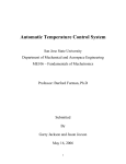
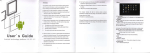
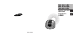
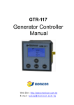
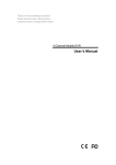
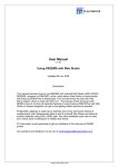
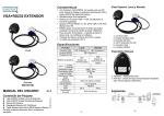
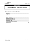
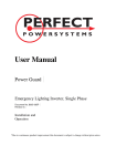
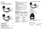
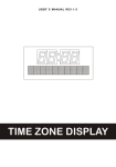
Document No: WI-JS-400-006
Edition:A/0
ZCTR02A User Manual
Description
Ⅰ.Description
Description:
ZCTR02A is a display which researched for ZCT245 series dual axis tilt sensor and used for
display the current output angle value. Users can also set the alarm angle according to one’s
requirement. when the received angle value more than the alarm angle, ZCTR02A light is power
on to alarm. at the same time, the internal relay will be closed, trigger an external control circuit,
consequently play a controlling role.
Technical data
Ⅱ.Technical
data:
Parameter
Value
Unit
Remark
Operating Voltage Range
9~36
V
DC
Quiescent current
<80
mA
Display Resolution
0.1
Degree
Baud Rate
9600
bps
Operating current
-20~+60
℃
Operating Voltage of
Relay
Max:277
V
V
AC
DC
Loading Capacity of
Relay
10A 277VAC
Outline Size
72*72*120
mm
W*L*H
Definition of Connector:
Ⅲ.Definition
Shanghai Zhichuan Electronic Tech Co.,Ltd
ADD:3/F,1128 Denghui Rd., Minhang district, Shanghai, 201109,China.
TEL:+86-021-64908096 Http://www.zc-sensor.com
Page 1 of 5
Document No: WI-JS-400-006
Edition:A/0
1.PIN1:connect power anode.
2.PIN2:connect power GND;
3.PIN3:connect RX of ZCT245-TTL series;
4.PIN4:connect TX of ZCT245-TTL series;
5.PIN5:connect GND of ZCT245 series tilt sensor
6.PIN6:connect +5V power supply for ZCT245 series tilt sensor;
7.PIN7:connect RX of ZCT245-232 series tilt sensor;
8.PIN8:connect TX of ZCT245-232 series tilt sensot;
9.PIN9:Relay side A1-2 which controlled by X axis, connect external control circuit;
10.PIN10:Relay side A1-1 which controlled by X axis, control external circuit coordinated with
A1-2;
11.PIN11:Relay side A2-2 which controlled by Y axis, connect external control circuit;
12.PIN12:Relay side A2-1 which controlled by Y axis, control external circuit coordinated with
A2-2;
ZCTR02A connect ZCT245 series tilt sensor
Ⅳ.ZCTR02A
ZCTR02A connect ZCT245-TTL
ZCT245-TTL:
ZCTR02A connect ZCT245-232
ZCT245-232:
Shanghai Zhichuan Electronic Tech Co.,Ltd
ADD:3/F,1128 Denghui Rd., Minhang district, Shanghai, 201109,China.
TEL:+86-021-64908096 Http://www.zc-sensor.com
Page 2 of 5
Document No: WI-JS-400-006
Edition:A/0
Remark:
1、 when connect ZCT245 series tilt sensor as above wiring diagram, please make sure the
operating voltage of tilt sensor is +5 V. If not, you need another power supply to this tilt
sensor;
2、 It can not be simultaneously connect ZCT245-TTL and ZCT245-232 series tilt sensor. That
means when the PIN3, PIN4 connect ZCT245-TTL series tilt sensor, PIN7, PIN8 can not
connect ZCT245-232 series tilt sensor, and vice versa;
3、 This display does not support other Zhichuan sensor.
ZCTR02A internal relay user instruction:
Ⅴ.ZCTR02A
Take A1 which controlled by X axis connect a alarm as an example:
Divider resistance
When ZCTR02A receive X-axis tilt angle which is less than the alarm angle, the relay has no
action, this time the external circuit is broken; When ZCTR02A receive X-axis tilt angle which is
large than the setted alarm angle, the corresponding alarm light on, at the same time, relay pull-in,
so that the external circuit switch on.
Relay A2 which controlled by Y axis, and PIN11,P12 use way is same as A1.
Shanghai Zhichuan Electronic Tech Co.,Ltd
ADD:3/F,1128 Denghui Rd., Minhang district, Shanghai, 201109,China.
TEL:+86-021-64908096 Http://www.zc-sensor.com
Page 3 of 5
Document No: WI-JS-400-006
Edition:A/0
Notice:
When using,please notice the maximum voltage and the maximum current that the relay can
afford.
Button operation instruction:
Ⅵ.Button
Button explanation:
1:Mode button: For switching system’s main states and return system from sub-state. There are
total 4 state in system:state0、state1、state 2、state3,and there are 3 sub-state: state4、state5、
state6. Switching method as the follow instruction diagram;
2:Setting button:For entering state4、state 5、state6 from state1、state2、state3 and operate system
in the corresponding state 4、state5、state6. Detailed operation please see as below.
Button operation:
1.1:模式按键
Mode button
2.2:设置按键
Setting button
State0
1
2
State1
State4
1
1
1
2
State2
State5
1
1
2
State3
Stat6
1
Operating instruction
Ⅶ.Operating
instruction:
The display condition when switch between states is as below:
State 0: Default display dual-axis angle value, display 000 when not connect inclinometer.
State 1:Clear and waiting choosing, digital LED display 11 (the latter two of above four digit
show "11", the latter two of below four digit also show "11"). In this mode, it can
enter state 4 by setting button and then can set the relative zero of X axis and Y
axis.
State 2: Display dual-axis angle alarm. LED display the current alarm angle of X axis and Y
axis; The default alarm angle of X axis is 10 degrees in factory. In this mode, it can
enter state 5 by setting button, then can set the alarm angle of X axis;
State 3: Display dual-axis angle alarm. LED display the current alarm angle of X axis and Y
axis; The default alarm angle of Y axis is 10 degrees in factory. In this mode, it can
enter state 6 by setting button, then can set the alarm angle of Y axis;
Shanghai Zhichuan Electronic Tech Co.,Ltd
ADD:3/F,1128 Denghui Rd., Minhang district, Shanghai, 201109,China.
TEL:+86-021-64908096 Http://www.zc-sensor.com
Page 4 of 5
Document No: WI-JS-400-006
Edition:A/0
State 4: Set relative zero, set the current angle value of 2 axis as zero. It can successfully set
after pressing the Mode button (about 1 second). This feature is to send relevant
command to inclinometer. It will return absolute angle output when power off.
State 5: Setting X-axis alarm angle, press setting button add 1,the maximum value is 30,
when more than 30,it will re-start counting from 0;
State 6 : Setting Y-axis alarm angle, press setting button add 1,the maximum value is 30,
when more than 30,it will re-start counting from 0;
Ⅷ.Structure specification:
There are two four digit LED display in front of ZCTR02A. The upper 4 digit displays angle value
of X axis, the below 4 digit displays angle value of Y axis. There are two buttons for mode
switching and parameter setting; There are 12 connect pins on the back of ZCTR02A for connect
power supply, serial communication signal line and the control line of alarm.
Product picture
picture::
set
Mode
Order information:Part number
ZCTR02A
Specifications subject to change without notice!
Shanghai Zhichuan Electronic Tech Co.,Ltd
ADD:3/F,1128 Denghui Rd., Minhang district, Shanghai, 201109,China.
TEL:+86-021-64908096 Http://www.zc-sensor.com
Page 5 of 5