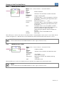
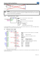
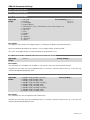
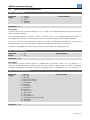
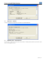
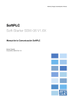
1
Motors | Energy | Automation | Coatings
SoftPLC
Soft-Starter SSW-06 V1.6X
SoftPLC Communication Manual
Language: English
Document: 0899.5722 / 03
SoftPLC Communication Manual
Series: SSW-06 V1.6X
Language: English
Document Number: 0899.5722 / 03
Publication Date: 09/2009
Summary
.
SUMMARY
INFORMATION ABOUT THE MANUAL.........................................................5
ABBREVIATIONS AND DEFINITIONS .......................................................................................................... 5
NUMERICAL REPRESENTATION................................................................................................................. 5
1 INTRODUCTION TO THE SOFTPLC ..........................................................6
1.1 SYMBOLS AND DATA TYPES............................................................................................................... 6
2 SOFTPLC MEMORY ...................................................................................7
2.1 DATA MEMORY...................................................................................................................................... 7
2.1.1 Constants ...................................................................................................................................... 7
2.1.2 Physical Inputs and Outputs (Hardware) ................................................................................... 7
2.1.3 Volatile Markers (Variables) ......................................................................................................... 7
2.1.4 System Markers ............................................................................................................................ 8
2.1.5 Parameters .................................................................................................................................... 9
3 RESUME OF THE FUNCTION BLOCKS ..................................................10
3.1 CONTACTS ........................................................................................................................................... 10
3.1.1 Normally Open Contact – NO Contact...................................................................................... 10
3.1.2 Normally Closed Contact – NC Contact................................................................................... 10
3.1.3 And Logic With Contacts ........................................................................................................... 10
3.1.4 Or Logic With Contacts.............................................................................................................. 10
3.2 COILS .................................................................................................................................................... 11
3.2.1 Normal Coil – Coil ....................................................................................................................... 11
3.2.2 Negated Coil – Neg Coil ............................................................................................................. 11
3.2.3 Set Coil – Set Coil ....................................................................................................................... 11
3.2.4 Reset Coil – Reset Coil............................................................................................................... 11
3.2.5 Positive Transition Coil – PTS Coil............................................................................................ 11
3.2.6 Negative Transition Coil – NTS Coil.......................................................................................... 11
3.3 CLP BLOCKS........................................................................................................................................ 12
3.3.1 Timer – TON................................................................................................................................. 12
3.3.2 Incremental Counter– CTU ........................................................................................................ 12
3.4 CALCULATION BLOCKS ..................................................................................................................... 12
3.4.1 Comparator – COMP .................................................................................................................. 12
3.4.2 Math Operation – MATH............................................................................................................. 13
3.4.3 Math Function – FUNC ............................................................................................................... 13
3.4.4 Saturator – SAT ........................................................................................................................... 14
3.4.5 Multiplexer – MUX....................................................................................................................... 14
3.4.6 Demultiplexer – DMUX ............................................................................................................... 15
3.5 TRANSFER BLOCKS............................................................................................................................ 15
3.5.1 Data Transfer – TRANSFER ....................................................................................................... 15
3.5.2 Indirect Data Transfer – IDATA ................................................................................................. 16
3.6 MULTIMOTOR CONTROL– MMC ...................................................................................................... 16
4 SSW-06 PARAMETER SETTINGS............................................................17
4.1 SYMBOLS FOR THE PROPRIETIES DESCRIPTION ......................................................................... 17
4.2 CONFIGURATION PARAMETERS ...................................................................................................... 17
4.3 SOFTPLC EXCLUSIVE PARAMETERS ............................................................................................... 20
5 RESUME OF THE WLP MAIN FUNCTIONS.............................................22
5.1
5.2
5.3
5.4
5.5
5.6
PROJECT – NEW.................................................................................................................................. 22
PROJECT – OPEN ................................................................................................................................ 22
VIEW – COMPILATION INFO............................................................................................................... 22
CONSTRUCT – COMPILE.................................................................................................................... 23
COMMUNICATION – CONFIGURATION ............................................................................................ 23
COMMUNICATION – DOWNLOAD ..................................................................................................... 24
Summary
.
5.7 COMMUNICATION – UPLOAD............................................................................................................ 24
Information About the Manual
INFORMATION ABOUT THE MANUAL
This manual provides the necessary description for the operation of the SSW-06 soft-starter using the user
programming module denominated SoftPLC. This manual must be used together with the SSW-06 user manual
and with the WLP software manual.
ABBREVIATIONS AND DEFINITIONS
PLC
CRC
RAM
WLP
Programmable Logic Controller
Cycling Redundancy Check
Random Access Memory
Ladder Language Programming Software
NUMERICAL REPRESENTATION
Decimal numbers are represented by means of digits without suffix. Hexadecimal numbers are represented with
the letter ‘h’ after the number.
SSW-06 | 5
Introduction to the SoftPLC
1
INTRODUCTION TO THE SOFTPLC
The SoftPLC is a feature that incorporates to the SSW-06 the functionalities of a PLC, adding flexibility to the
product and allowing the user to develop applicative software (user programs).
The SoftPLC main features are:
■ Ladder language programming, by using the WLP software;
■ Access to all the SSW-06 parameters and I/O’s;
■ 18 configurable user parameters;
■ PLC Mathematical and Control Blocks;
■ Applicative software transfer and online monitoring via serial (RS-232).
■ The cable (WEG Part Number: 10050215) shall be connected directly to the PC serial interface.
1.1
SYMBOLS AND DATA TYPES
%KW
%MX
%MW
%SX
%SW
%IX
%QX
%QW
%PW
%UW
word type constants (16 bit)
bit marker
word marker (16 bit)
system bit marker
system word marker (16 bit)
digital inputs
digital outputs
analog outputs (14 bit)
system parameters
user parameters
SSW-06 | 6
SoftPLC Memory
2
SOFTPLC MEMORY
The total size of the SoftPLC memory is 1024 bytes, between program memory and data memory.
2.1
DATA MEMORY
The SoftPLC data memory area (user variables) is shared with the programming memory. Therefore, the total
size of an applicative may vary as function of the amount of variables applied by the user.
The bit and word markers are allocated according to the LAST address used in the applicative, i.e., the higher
the last address the bigger the allocated area. Therefore, it is recommended to use the markers in a
SEQUENTIAL manner.
The word constants do also use program memory space.
2.1.1
CONSTANTS
Table 2.1: Constant Memory Map
Sym.
%KW
2.1.2
Description
Word Constants
(16 bit)
Bytes
It depends on the quantity of different word constants. E.g.: If there were used:
- %KW: 327
= 2 bytes
- %KW: 5; 67
= 4 bytes
- %KW: 13; 1000; 13; 4
= 6 bytes
PHYSICAL INPUTS AND OUTPUTS (HARDWARE)
Table 2.2: I/O Memory Map
Sym.
%IX
%QX
%QW
2.1.3
Description
Digital inputs
Digital outputs
Analog outputs
Range
1to 6 or 1 to 12 with K_IOE
1 ... 3 or 1 to 9 with K_IOE
1 ... 2
VOLATILE MARKERS (VARIABLES)
They consist of variables that can be applied by the user to execute the applicative logics. They can be bit
markers (1 bit) and word markers (16 bit).
Table 2.3: Volatile Marker Memory Map
Sym.
%MX
Description
Bit markers
Range
5000 ... 6099
%MW
Word markers
8000 ... 8199
Bytes
It depends on the last used marker. They are organized in byte pairs. E.g.:
- last marker: %MX5000
= 2 bytes
- last marker: %MX5014
= 2 bytes
- last marker: %MX5016
= 4 bytes
- last marker: %MX5039
= 6 bytes
It depends on the last used marker. E.g.:
- last marker: %MX8000
= 2 bytes
- last marker: %MX8001
= 4 bytes
- last marker: %MX8007
= 16 bytes
NOTE!
In order to minimize the applicative size, use the markers in a sequential manner.
E.g.:
Bit markers: %MX5000, %MX5001, %MX5002...
Word markers: %MW8000, %MW8001, %MW8002...
SSW-06 | 7
SoftPLC Memory
2.1.4
SYSTEM MARKERS
They consist of special variables that allow the user to read and change SSW-06 soft-starter data that may or
not be available in the parameters. They can be: system bit markers (1 bit) or system word markers (16 bit).
Table 2.4.a: Memory Map for the Odd System Bits
Sym.
Type
%SX
Description
System Bits
Range
3000 ... 3040
Description
writing/Commands (odd)
3001
Run/Stop
3003
General Enabling
3005
JOG
3007
Speed Direction
3009
LOC/REM
3015
Fault reset
0: It stops the motor.
1: It runs the motor.
0: It disables the soft-starter, interrupting the supply to the motor.
1: General enabling, allowing the motor operation.
0: It disables the JOG function.
1: It enables the JOG function.
0: It runs the motor in the clockwise direction.
1: It runs the motor in the counterclockwise direction.
0: It goes to the local mode.
1: It goes to the remote mode.
0: No function.
1: If in a fault condition, then it executes the SSW-06 reset.
Table 2.4.b: Memory Map for the Even System Bits
Sym.
Type
%SX
Description
System Bits
Range
3000 ... 3040
Description
Reading/State (Even)
3000
Motor Running
3002
General Enabling
3004
JOG
3006
In Acceleration
3008
In Current Limit
3010
At Full Voltage
3012
Alarm condition
3014
In Deceleration
3016
LOC/REM
3018
Braking
3020
Changing the speed direction
3022
Speed direction
3024
Bypass
3028
Supply at the power section
3030
Fault condition
0: The motor is stopped.
1: The motor is running, or executing either the acceleration or
deceleration ramp, or braking.
0: General Enabling is not active.
1: General Enabling is active and the soft-starter is ready to run the
motor.
0: Inactive JOG function.
1: Active JOG function.
0: It is not executing the acceleration ramp.
1: It is executing the acceleration ramp.
0: It is not in current limit.
1: It is in current limit.
0: The motor is not with full voltage.
1: The motor is with full voltage.
0: It is not in alarm condition.
1: It is in alarm condition.
Note: The alarm number can be read iby means of the parameter
P021 – Current Alarm.
0: It is not executing the deceleration ramp.
1: It is executing the deceleration ramp.
0: It is in local mode.
1: It is in remote mode.
0: It is not braking.
1: It is braking.
0: It is not executing the speed direction change.
1: It is executing the speed direction change.
0: The motor is rotating clockwise.
1: The motor is rotating counterclockwise.
0: It is not with closed bypass.
1: It is with closed bypass.
0: It is without supply at the power section.
1: It has a supply higher than 15V at the 3 phases of the power
section.
0: It is not in a fault condition.
1: It is in fault condition.
SSW-06 | 8
SoftPLC Memory
Table 2.5: Memory Map for the System Word Markers
Sym.
%SW
Description
System Words
Range
3300 ... 3303
Writing markers/Command (Odd)
3303
3305
2.1.5
User Fault (E86 to E89)
User Alarm (A90 to A93)
PARAMETERS
The SSW-06 soft-starter parameter memory map is described in the table 2.6.
Table 2.6 : Parameter Memory Map
Sym.
%PW
Description
System parameters
(Refer to the SSW-06 manual)
P088: SoftPLC status
[Read-only parameter]
P089: SoftPLC Allowed
P204: Load/Save parameters
P950: Enable SoftPLC
%UW
P951: Digital Inputs and Outputs Expansion
Card Enable (K-IOE)
User Parameters
Range
0... 950
0: Without
1: Loading
2: Fault
3: Stopped
4: Running
0: No
1: Yes
13: Erase SoftPLC
14: Reset user parameters (P952 to P969 = 0)
0: No
1: Yes
0: No
1: Yes
952... 969
SSW-06 | 9
Resume of the Function Blocks
3
RESUME OF THE FUNCTION BLOCKS
A resume of the function blocks that are available for the user programming, will be presented in this chapter.
3.1
CONTACTS
They send to the stack the content of a programmed data (0 or 1), which may be of the type:
■ %MX: Bit Marker
■ %IX: Digital Input
■ %QX: Digital Output
■ %UW: User Parameter
■ %SX: System Bit Marker - Reading
NOTE!
If contacts with parameters are used (%UW), they are set when the parameter value is different from
zero. In the logic examples below, the %UW952 contact is considered active if the parameter P952
is different from zero.
3.1.1
NORMALLY OPEN CONTACT – NO CONTACT
Menu: Insert – Contacts – Normally Open Contact.
E.g.: It sends to the stack the content of the bit marker 5000.
3.1.2
NORMALLY CLOSED CONTACT – NC CONTACT
Menu: Insert – Contacts – Normally Closed Contact.
E.g.: It sends to the stack the negated content of the digital output 1.
3.1.3
AND LOGIC WITH CONTACTS
When the contacts are in series, an AND logic is executed among them, storing the result in the stack.
Examples:
Example
%IX1 . %IX2
%UW952 . (~%QX1)
3.1.4
%IX1
0
0
1
1
%UW952
0
0
1
1
Truth Table
%IX2
0
1
0
1
%QX1
0
1
0
1
Stack
0
0
0
1
Stack
0
0
1
0
OR LOGIC WITH CONTACTS
When the contacts are in parallel, an OR logic is executed among them, storing the result in the stack.
Examples:
SSW-06 | 10
Resume of the Function Blocks
Example
3.2
Operation
Truth Table
%IX2
Stack
0
0
1
1
1
0
1
1
%IX1 + %IX2
%IX1
0
0
1
1
%UW952+ (~%QX1)
%UW952
0
0
1
1
%QX1
0
1
0
1
Stack
1
0
1
1
COILS
They save the stack content (0 or 1) in the programmed element:
■ %MX: Bit Marker
■ %QX: Digital Output
■ %UW: User Parameter
■ %SX: System Bit Marker – Writing
It is allowed to add coils in parallel at the last column.
3.2.1
NORMAL COIL – COIL
Menu: Insert – Coils – Coil.
E.g.: It sets the bit marker 5001 with the stack content.
3.2.2
NEGATED COIL – NEG COIL
Menu: Insert – Coils – Negated Coil.
E.g.: It sets the digital output 2 with the negated content of the stack.
3.2.3
Set Coil – Set Coil
Menu: Insert – Coils – Set Coil.
E.g.: It sets the user parameter P960, provided that the content of the stack is not 0.
3.2.4
Reset Coil – Reset Coil
Menu: Insert – Coils – Reset Coil.
E.g.: It resets the user parameter P960, provided that the content of the stack is not 0.
3.2.5
Positive Transition Coil – PTS Coil
Menu: Insert – Coils – PTS Coil.
E.g.: It sets the bit marker 5002 during 1 scan cycle, provided that a transition from 0 to 1 in
the stack is detected.
3.2.6
Negative Transition Coil – NTS Coil
Menu: Insert – Coils – NTS Coil.
E.g.: It sets the system bit marker 3011 during 1 scan cycle, provided that a transition from 1
to 0 in the stack is detected.
SSW-06 | 11
Resume of the Function Blocks
3.3
3.3.1
CLP BLOCKS
Timer – TON
Menu: Insert - Function Blocks – PLC-TON.
Input:
IN:
Enables the block.
Output:
Q:
Goes to 1 when IN ≠0 and ET ≥ PT.
Proprieties:
PT:
Programmed Time (Preset Time).
ET:
Elapsed Time.
If the IN input is active and the content of the word marker 8000 is higher or equal than the content of the user
parameter P955, the output Q is set.
3.3.2
Incremental Counter– CTU
Menu: Insert - Function Blocks – PLC-CTU.
Inputs:
CU: Captures the transitions from 0 to 1 at this input (Counter
Up).
R:
Resets CV.
Output:
Q:
Goes to 1 when CV ≥ PV.
Proprieties:
PV:
Programmed Value (Preset Value).
CV: Counter Value.
If the content of the word marker 8001 is higher or equal than 20, the output Q is set.
3.4
3.4.1
CALCULATION BLOCKS
Comparator – COMP
Menu: Insert - Function Blocks – Calculation-COMP.
Input:
EN:
Enables the block.
Output:
ENO:
Goes to 1 when the comparison condition is
fulfilled.
Proprieties:
FORMAT:
Only Integer.
DATA 1:
Comparison data 1.
OPERATOR:
Comparison operator.
DATA 2:
Comparison data 2.
If the EN input is active and the content of the word marker 8000 is higher than the content of the word marker
8001, then the output ENO is set.
NOTE!
All the numeric data are considered words of 15 bit + sign (-32768 to 32767).
SSW-06 | 12
Resume of the Function Blocks
3.4.2
MATH Operation – MATH
Menu: Insert - Function Blocks – Calculation-MATH.
Input:
EN:
Enables the block.
Output:
ENO:
Indicates if the calculation has been executed.
Proprieties:
FORMAT:
Integer or floating point.
DATA1:
Calculation data 1. It may also appear as DATA1H
and DATA1L (representing the high and low parts
of the data 1).
OPERATOR:
Mathematic operator (+, -, *, etc).
DATA2:
Calculation data 2. It may also appear as DATA2H
and DATA2L (representing the high and low parts
of the data 2).
RES:
Calculation result. It may also appear as RESH
and RESL (representing the high and low parts of
the result) and also as QUOC and REM
(representing the quotient and the reminder of a
division).
OVER:
Indicates if the result exceeded its limit.
SIGNAL:
Result sign.
When EN input is active, the value of the word marker is incremented to each cycle of scan. When the bit
marker 5000 goes for 1, indicates that it had a overflow limit and the word marker 8000 remains in 32767.
NOTE!
All the numeric data are considered words of 15 bit + sign (-32768 to 32767).
3.4.3
MATH Function – FUNC
Menu: Insert - Function Blocks – Calculation-FUNC.
Input:
EN:
Enables the block.
Output:
ENO:
Indicates if the calculation has been executed.
Proprieties:
FORMAT:
Only Integer.
IN:
Data to be calculated.
FUNCTION:
Mathematic function: abs (module) and neg
(negative).
OUT:
Calculation result.
When the EN input is active, the word marker 8001 presents the module of the word marker 8000.
NOTE!
All the numeric data are considered words of 15 bit + sign (-32768 to 32767).
SSW-06 | 13
Resume of the Function Blocks
3.4.4
Saturator – SAT
Menu: Insert - Function Blocks – Calculation-SAT.
Input:
EN:
Enables the block.
Output:
ENO:
Indicates if saturation has occurred, provided that
EN ≠ 0.
Proprieties:
FORMAT:
Only Integer.
IN:
Input data.
MAX:
Maximum allowed value.
MIN:
Minimum allowed value.
OUT:
Output data.
When the EN input is active, the word marker 8000 contains the user parameter P952 value, limited however
between the maximum of 100 and the minimum of -100.
NOTE!
If the minimum value is higher than the maximum, the outputs OUT and ENO are reset to zero.
NOTE!
All the numeric data are considered words of 15 bit + sign (-32768 to 32767).
3.4.5
Multiplexer – MUX
Menu: Insert - Function Blocks – Calculation-MUX.
Input:
EN:
Enables the mathematic operation.
Output:
ENO:
Indicates that the transfer has been done.
Proprieties:
X0-X15:
Binary data vector.
W:
Resulting word.
When the EN input is active, the digital inputs 1, 2 and 3 transfer their content to the bits 0, 1 and 2 of the user
parameter P952.
SSW-06 | 14
Resume of the Function Blocks
3.4.6
Demultiplexer – DMUX
Menu: Insert - Function Blocks – Calculation-MUX.
Input:
EN:
Enables the mathematic operation.
Output:
ENO:
Indicates that the transfer has been done.
Proprieties:
W:
Source word.
X0-X15:
Resulting binary data vector.
When the EN input is active, the bits 1, 2, 5, 6, 11, 13 and 15 of the word marker 8000 are transferred
respectively to the bit markers 5001, 5002, 5005, 5006, 5011, 5013 and 5015.
3.5
3.5.1
TRANSFER BLOCKS
Data Transfer – TRANSFER
Menu: Insert - Function Blocks- Transfer-TRANSFER.
Input:
EN:
Enables the block.
Output:
ENO:
Indicates that the transfer has been done.
Proprieties:
SRC:
Source data.
DST:
Destine data.
In the example above, if the EN input is active, the word constant 1 is transferred to the system bit marker 3001
(Run/Stop).
TRANSFER for the generation of user faults and alarms
In order to generate the user alarms A90 to A93 and the user faults E96 to E99, the TRANSFER block must be
used according to the examples below.
The fault reset may come from the system bit marker %SX3011, or from other reset source (HMI, DIx, etc.).
E86 fault generated with the transfer block.
A90 alarm generated with the transfer block.
NOTE!
By using user faults, precaution must be taken in order to avoid that the transfer block EN input does
not stay always active, with a reset also always active. This would cause the soft-starter SSW-06 to
stay in a fault and reset loop, as showed below.
SSW-06 | 15
Resume of the Function Blocks
Logic for the fault and reset loop.
NOTE!
The user alarms can only be reset with the command coming through the SoftPLC, in this case the
SCR of the transfer block must contain the value zero. The SSW-06 soft-starter alarms can be reset
only by the source that has generated them.
3.5.2
Indirect Data Transfer – IDATA
Menu: Insert - Function Blocks- Transfer -IDATA.
Input:
EN:
Enables the block.
Output:
ENO:
Indicates that the transfer has been done.
Proprieties:
CMD: Read/Write command
DATATYPE:
Data type
ADDRESS:
User address.
VALUE:
Read content/Value to be written
In the example above, if the EN input is active, the content of the bit marker 5000 is written to the digital output
whose address is the content of the word marker 8000.
3.6
Multimotor Control – MMC
Menu: Insert-Function Block multimotor control-MMC
Input:
EN:
Enables the block.
Output:
ENO:
Indicates that the block is active.
Proprieties:
MotorX
START:
Enable the motor in 1.
STOP:
Disable the motor in 0.
FAULT:
Disable the motor in 0.
STARTING: Indicates motor starting or stopping.
BYPASS:
Indicates by-pass on.
SRC1:
Source data.
SRC2:
Source data.
SRC3:
Source data.
DST1:
Destine data.
DST2:
Destine data.
DST2:
Destine data.
In the example above, through the MMC you can control the start and stop of up to three different motors only
one Soft-Starter SSW-06.
SSW-06 | 16
SSW-06 Parameter Settings
4
SSW-06 PARAMETER SETTINGS
In the continuation, only the parameters of the SSW-06 soft-starter that are related to the SoftPLC will be
presented, remembering that all the parameters are accessible, except for the parameters P200 and P215.
Refer to the SSW-06 manual for more details.
4.1
SYMBOLS FOR THE PROPRIETIES DESCRIPTION
Read-only parameter.
Parameter that can be changed only with a stopped motor.
RO
CFG
4.2
CONFIGURATION PARAMETERS
P220 – LOCAL/REMOTE Source Selection
Adjustable
Range:
0 = Always LOCAL
1 = Always REMOTE
2 = Keypad (L)
3 = Keypad (R)
4 = DI4 to DI6
5 = Serial (L)
6 = Serial (R)
7 = Fieldbus (L)
8 = Fieldbus (R)
9 = SoftPLC (L)
10 = SoftPLC (R)
Factory Setting: 2
Proprieties: CFG
Description:
It defines the origin of the command that will select between the LOCAL situation and the REMOTE situation.
Default situation is the one assumed when the Soft-Starter SSW-06 is powered-up (initialization).
Table 4: OCAL / REMOTE Selection
P220
0
1
2
3
4
5
6
7
8
9
10
LOCAL / REMOTE Selection
Always Local situation
Always Remote situation
HMI key
(Default LOCAL)
HMI key
(Default REMOTE)
Digital inputs from DI1 to DI6 (P266 to P268)
Serial (Default Local) – SuperDrive or incorporated Modbus
Serial (Default Remote) – SuperDrive or incorporated Modbus
Fieldbus (Default Local) – Optional interface module
Fieldbus (Default Remote) – Optional interface module
SoftPLC (Default Local)
SoftPLC (Default Remote)
P229 – Command Selection – LOCAL Situation
P230 – Command Selection – REMOTE Situation
Adjustable
Range:
0 = HMI keys
1 = Digital input DIx
2 = Serial
3 = Fieldbus
4 = SoftPLC
Factory Setting:
P230 = 1
P229 = 0
SSW-06 | 17
SSW-06 Parameter Settings
Proprieties: CFG
Description:
They define the origin of the commands for running and stopping the SSW-06 soft-starter.
Table 4.2: LOCAL / REMOTE Command Selection
P229/P230
0
1
2
3
4
LOCAL / REMOTE Command Selection
HMI keys
Digital input DIx
Serial communication
Fieldbus communication (DeviceNet or Profibus DP)
SoftPLC
P251 – AO1 Function (0 to 10V)
P253 – AO2 Function (0 to 20mA or 4 to 20mA)
Adjustable
Range:
0 = Not used
1 = SSW current (% of the SSW In)
2 = Line Voltage (% of the SSW Un)
3 = Output voltage (% of the SSW Un)
4 = Power factor
5 = Thermal protection
6 = Power (in W)
7 = Power (in VA)
8 = Torque (% of the motor Tn)
9 = Fieldbus
10 = Serial
11 = SoftPLC
Factory Setting: P251 = 0
P253 = 0
Description:
These parameters set the functions of the analog outputs, according to the table 4.6.
The value of the analog outputs can be read at the parameters P027 (AO1) and P028 (AO2). Those values are
converted to voltage and current using the full scale values as showed in the table below. Thus, if the AO1 was
programmed for SoftPLC (P251 = 11) and the value 16383 is written, the analog output will present 10v.
The same criteria is valid for the analog output in current (AO2), where the value 16383 will be equal to 20mA
and 0 will be either equal to 0mA or to 4mA, depending on the analog output programming (P255=0 (0 to
20mA) or P255=1 (4 to 20mA)).
Table 4.6: Analog output functions
Functions
P251
(AO1)
P253
(AO2)
Full scale when
Not used
SSW current in % of the SSW In
Line Voltage in % of the SSW Un
Output voltage in % of the SSW Un
Power factor
Thermal protection
Power in W
Power in VA
Torque in % of the motor Tn
Fieldbus
Serial
SoftPLC
0
1
2
3
4
5
6
7
8
9
10
11
0
1
2
3
4
5
6
7
8
9
10
11
5 x P295
1.5 x P296(max.)
1.5 x P296(max.)
P008 = 1.00
P050 = 250%
1.5 x √3 x P295 x P296(max.) x P008
1.5 x √3 x P295 x P296(max.)
P009 = 100%
16383 (3FFFh)
16383 (3FFFh)
16383 (3FFFh)
SSW-06 | 18
SSW-06 Parameter Settings
P277 – DO1 Function (RL1)
P278 – DO2 Function (RL2)
P279 – DO3 Function (RL3)
Adjustable
Range:
0 = Not used
Factory Setting: P277 = 1
1 = Running
P278 = 2
2 = Full Voltage
P279 = 6
3 = External Bypass
4 = FWD/REV-K1 (P277) / FWD/REV-K2 (P278) / Not used (P279)
5 = DC braking
6 = No Fault
7 = Fault
8 = Fieldbus
9 = Serial
10 = SoftPLC
11 = No Alarm
12 = Alarm
Description:
They program the functions of the digital outputs, according to the options presented previously.
When the condition declared by the function is true, the digital output will be activated.
The status of the digital outputs can be monitored via the parameter P013.
P308 – Soft-Starter address on the Serial Communication Network
Adjustable
Range:
1 to 247
Factory Setting: 1
Description:
This parameter sets the address of the SSW-06 soft-starter in the serial communication network.
The SSW-06 soft-starter must be configured exactly as in the WLP software (refer to item 5.6), so that the user
software download/upload be possible.
P312 – Protocol Type and Baud Rate of the Serial
Adjustable
Range:
1 = Modbus-RTU (9600bps, no parity)
2 = Modbus-RTU (9600bps, odd)
3 = Modbus-RTU (9600bps, even)
4 = Modbus-RTU (19200bps, no parity)
5 = Modbus-RTU (19200bps, odd)
6 = Modbus-RTU (19200bps, even)
7 = Modbus-RTU (38400bps, no parity)
8 = Modbus-RTU (38400bps, odd)
9 = Modbus-RTU (38400bps, even)
Factory Setting: 1
Description:
This parameter sets the serial protocol and the baud rate.
The SSW-06 soft-starter must be configured exactly as in the WLP software (refer to item 5.6), so that the user
software download/upload be possible.
SSW-06 | 19
SSW-06 Parameter Settings
4.3
SOFTPLC EXCLUSIVE PARAMETERS
P088 – SoftPLC Status
Adjustable
Range:
0 = Without
1 = Loading
2 = Fault
3 = Stopped
4 = Running
Factory Setting:
-
Proprieties: RO
Description:
It allows to the user to visualize the SoftPLC status. If there is no installed applicative, the parameter P088 will
show the option 0 (Without).
If this parameter presents the option 2 (Fault), it indicates that the user software loaded with the WLP is
incompatible with the SSW-06 firmware version, or that an error occurred during the program download.
In this case it is necessary to recompile the project in the WLP, considering the new SSW-06 version, and to
download it again. If this is not possible, the upload of this applicative with the WLP can be done.
The options 3 (Stopped) and 4 (Running) are related to the parameter P950 (Enable SoftPLC).
P089 - SoftPLC Allowed
Adjustable
Range:
0 = No
1 = Yes
Factory Setting:
-
Proprieties: CFG
Description:
The SSW-06 soft-starter SoftPLC feature is available from the firmware version V1.40 on; however, it is
necessary to upgrade the control board to one with more memory in order to allow the SoftPLC operation.
Therefore, the parameter P089 verifies whether the hardware version is compatible (P089 = 1) or not (P089 = 0).
P204 – Load/Save Parameters
Adjustable
Range:
0 = Not used
1 = Not used
2 = Not used
3 = Reset P043 to P050
4 = Reset P053 to P058
5 = Load Default
6 = Not used
7 = Load User 1
8 = Load User 2
9 = Not used
10 = Save User 1
11 = Save User 2
12 = Not used
13 = Erase SoftPLC
14 = Reset SoftPLC (P952 to P969)
15 = Reserved
16 = Reserved
Factory Setting:
0
Proprieties: CFG
SSW-06 | 20
SSW-06 Parameter Settings
Description:
The parameter P204 loads, saves and resets several parameters, as describe in the list above. The options
related to the SoftPLC are: the option 13, which erases the user program, and the 14, which resets the user
parameters P952 to P969.
P950 – Enable SoftPLC
Adjustable
Range:
0 = No
1 = Yes
Factory Setting:
0
Proprieties: CFG
Description:
It makes it possible to run and to stop an installed applicative, but therefore the motor must be disabled.
P951 – Digital Inputs and Outputs Expansion Card Enable
Adjustable
Range:
0 = No
1 = Yes
Factory Setting:
0
Proprieties: CFG
Description:
It makes it possible to enable digital inputs and outputs expansion card of Kit K-IOE, with: six digital inputs
24Vcc (of DI7 to DI12) and six digital relay outputs(of RL4 to RL9).
P952 to P969 – SoftPLC Parameters
Adjustable
Range:
0 to 65535
Factory Setting:
0
Description:
They consist of parameters with functions defined by the user by means of the WLP software.
SSW-06 | 21
Resume of the WLP Main Functions
5
RESUME OF THE WLP MAIN FUNCTIONS
This chapter brings basic information about the operations done with the WLP software for the SSW-06 softstarter programming. More information can be obtained in the manual or in the help of the WLP software.
5.1
PROJECT – NEW
It creates a new project. Besides defining the project name, it is also necessary to configure the equipment and
the respective firmware version.
5.2
PROJECT – OPEN
It opens the selected project.
5.3
VIEW – COMPILATION INFO
It allows the user to know the compiled applicative size in bytes (<projectname>.bin) to be sent to the
equipment.
SSW-06 | 22
Resume of the WLP Main Functions
5.4
CONSTRUCT – COMPILE
It analyses the applicative and generates the code for the specified equipment.
5.5
COMMUNICATION – CONFIGURATION
The serial port is used for the communication with the SSW-06. Therefore, both the SSW-06 and the WLP baud
rate must be configured correctly.
SSW-06 | 23
Resume of the WLP Main Functions
5.6
COMMUNICATION – DOWNLOAD
This command allows downloading the applicative to the SSW-06.
5.7
COMMUNICATION – UPLOAD
This command makes it possible to upload the applicative installed in the SSW-06.
SSW-06 | 24