1
Features
•
•
•
•
•
•
Basics:
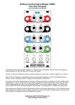
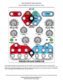
• Dual “pingable” envelope generator – total envelope time is set by time between pulses ("ping")
• Tap tempo button or external clock/triggers sets the ping time
• Two taps sets the tempo. If a third tap is given close to the tempo to the first two taps, the two timing periods
will be averaged
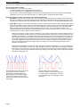
• Envelope time is a multiple or division of the ping clock (from /8 to x8) set by Ping Div/Mult knob and CV
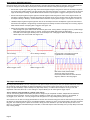
• Curve knob and CV control the shape of the output envelope. Various combinations of exponential, linear,
logarithmic, and interpolated curves, separately for rise and fall portions
• Skew knob and CV control the ratio between rise and fall times without changing total envelope time.
• Fastest rise time=10µs, fastest fall time=100µs. Slowest rise/fall time=15 min (30 min total)
• Envelope is triggered by Quantized trigger jack, Asynchronous trigger jack, and/or Cycle mode
Outputs and scaling/shifting:
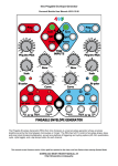
• Scale knob is an attenuating inverter for main envelope output
• Maximum 0V to +10V non-inverted
• Minimum -10V to 0V inverted
• Bi-polar button centers main envelope output around 0V (-5V to +5V output)
• “+5V ENV” jack is a non-scaling output that always produces a 0V to +5V envelope
• “OR” jack outputs an analog OR mix of the two channels' scaled envelope curves
Gate/Trigger outputs:
• End-of-Rise (EOR) gate output goes high when envelope finishes a rise portion, and goes low when envelope
begins a rise portion. Optional trigger mode
• End-of-Fall (EOF) gate output goes high when envelope finishes a fall portion, and goes low when envelope
begins a fall portion. Optional trigger mode
• Half-R (Half-Rise) gate outputs 90-degree phase shifted gates that go high when 50% of the time of the rise
portion has elapsed, and goes low after 50% of the time of the fall portion (this is different than a voltage
comparator-based design). Optional trigger mode
• Tap Clock Output: (enabled in System Edit Mode) dedicated Tap Tempo clock output (gate or trigger)
Triggering/cycling:
• Cycle button for each channel makes envelope self-cycle (LFO mode). Button lights up when on
• “T” jack toggles the state of both channels' Cycle buttons while a gate is applied
• “QNT” jack for each channel triggers an envelope to start at the next quantized beat, with respect to the
divided/multiplied ping clock. Holding a gate high on this jack causes the envelope to repeat.
• “Async” jack for each channel causes an envelope to output immediately (asynchronously). Holding a gate high
results in an AR envelope (rise-sustain-fall). A trigger on Async jack enters Async mode, where the envelope is
no longer phase-locked to the ping clock. A trigger on QNT exits Async mode and enters Sync mode.
CV input jacks:
• CV control of each channel's Ping Div/Mult, Skew, and Curve using the CV jacks.
• Respective knobs set the center offset for the applied CV
• CV of 0-10V will modulate the parameter's full range – however, a 0-5V CV will modulate the parameter within
a useful range.
System Mode:
• Special mode to change advanced parameters
• Re-assign the Half-Rise jack to EOR (and vice-versa)
• Re-assign the EOF jack to Tap Tempo Clock output
• Select Gate or Trigger output from EOR/EOF/Half-R jacks
• Require a continuous external ping clock (unit will not free-run if external ping clock stops)
• Enable/disable skew limiting that keeps fastest rise/fall times at 6ms
Dimensions
•
•
20 HP Eurorack format module
1.6” (40mm) deep
Power consumption
+12V rail:
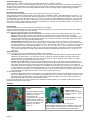
60mA max with 5V Source jumper selecting external 5V
105mA max with 5V Source jumper selecting internal 5V
+5V rail:
40mA max with 5V Source jumper selecting external 5V
not used with 5V Source jumper selecting internal 5V
-12V rail:
35mA max
Page 2