1
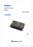
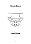
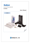
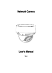
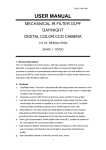
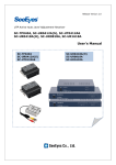
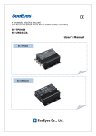
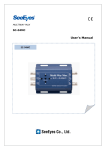
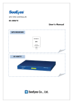
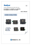
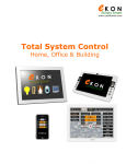
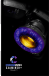
4 CHANNEL VIDEO INPUT DIGITAL SPLITTER SC-40DQH/F, VGA User's Manual SC-40DQH SC-40DQF 1 Precaution and Safety Guidelines Please read this user’s manual thoroughly prior to use the unit for its easy and convenient use. • Do not install the product in the following places: extremely low or high temperature conditions; places exposed to rain, snow, or high humidity; places containing or exposed to oil and gas; places exposed to vibration and shock; places under direct sunlight or exposed to outdoor weather conditions; places exposed to radio waves (RF) or near to power lines. It may cause low performance or malfunction of the unit. • Do not disassemble the product or insert foreign objects. • The unit is subject to electric shock hazard. Be careful not to get an electric shock while using the device. • Please use only electrical safety approved power supply unit (power adapter) over 12VDC /0.5A (12VDC/0.8A for SC-40DQH with VGA output) with electromagnetic compatibility. • Do not use and/or connect any devices inappropriate to the unit. It may cause malfunction of the unit or fire. • Use this product under temperature conditions only between 0°C and +40°C. • Should be careful not to have the lines changed when connecting them. • Prior to turn on the device, check the cable insulation condition of the data cable, connected with external devices. • Before installing the product, check its voltage rate and then turn on the power. • Make sure to turn off the product prior to installation. • Do not subject the product to physical shock or exert excessive force to operate the product. • Do not use the device when any smoke or smell is produced from the unit. It may be subject to fire or electric shock. If any smoke or smell is produced, please turn off the unit and remove the power cable immediately, and contact your distributor to check the device properly. • If the power does not turn ON, please check whether the power cable is connected correctly or not. • In places where the events happen often, please set off the Event Set in the Menu mode (SYSTEM/DISPLAY). Otherwise, it may damage the EEPROM (Electrically Erasable Programmable Read-Only Memory) of the unit. • If the device does not work properly, please contact your distributor. 1 1. Introduction 1.1. Overview Using the SC-40DQH/F, you can split a video monitor into full/2/4 screens or configure to auto sequence mode. There are two types of size: the SC-40DQH, half rack type, and the SC-40DQF, full rack type. As optional, there is a 4 ch quad splitter, the SC-40DQH(VGA), with VGA output. Without a quad, you would only be able to view one camera at a time. This kit is useful when you are using more than one camera and using a VCR to record or when you are just monitoring the video without recording it. Our quad splitter offers high resolution real time and supports up to 4 cameras. Also, it is possible to display selectively when the camera detects the motions. It displays the name of channel, date and time as well as event such as loss. 1.2. Features - No rolling noise in full screen in auto sequence or in motion detection mode - Sustaining clear and stable video (over 500 TVL with full screen) - Two types: 1U (SC-40DQF), 1/2U (SC-40DQH) - Space saving model with user friendly buttons - RS-485 connector for other device connection - 4 Alarm input / 1 Alarm output - VGA output for LCD monitor (Optional) 1.3. Application - Where a centralized supervisory and control system is needed such as the control center at subway, airport, port and etc, - At a control center of large buildings and express way and etc. 2. Components Please find the following components in the package. Model # Mount Bracket Product SC40DQH SC40DQF 2 Power Cord or Adapter User’s Manual 3. Product Parts and Peripheral Device Connection 3.1. Name of Parts and Function 3.1.1. SC-40DQH Front Side ① ② ③ ④ ⑤ ⑥ ⑦ ⑧ Buttons Functions ① MENU Press this button to display the “SETUP MENU”. With this button, you can enter to the sub menu, confirm the setting value in the menu mode and cancel the alarm ring manually. ② DUAL Press this button to display the video signals of Ch # 1 and Ch # 2 in vertical dual split mode. If you press again this button, it displays the video signals of Ch # 3 and Ch # 4 in vertical dual split mode. Press this button for 2 secs. and you can playback the recorded video at the VCR. And if you press the single button of each channel in PLAY mode, you can scale double up the video of the channel selected. ③ AUTO Press this button to display the videos in full screen in auto sequence at the set-up DWELL TIME of each channel. If you press this button again, the button LED will light and it will activate the „Motion Detect Sequence Mode‟ displaying automatically the video of the camera at which a motion is detected. This function is very useful when you want to surveil the camera only with motion. When there is any motion with the alarm on, it sounds a short alert ring. To return to the Sequence mode, simply press this button again. ④ QUAD Press this button to start the quad display. If you press this button again, it will enter to the Freeze mode, the button LED will light, and all 4 channels‟ video will be freeze. If you press the SINGLE (channel select) button, the video of the channel selected is freeze and if you press once again the SINGLE button, it cancels the freeze video. To cancel the video freeze and to return to quad mode, press this button again. In Setup menu mode, it exits from the menu. ⑤ ~ ⑧ SINGLE DISPLAY Press these buttons to select the channel from CH1, CH2, CH3 and CH4 in a clockwise direction from the button #6. In the Menu mode, you can use these buttons as up, down, right and left direction buttons, or to change the value setting. The selected channel is displayed in full screen at quad or sequence mode. 3 - Quad mode SINGLE DISPLAY BUTTON DUAL KEY BUTTON QUAD BUTTON 3.1.2. SC-40DQH Back Side ① ② ③ ⑧ ⑨ ④ ⑤ ⑩ ⑥ ⑦ ⑪ ① CAMERA IN: Connect the camera. ② Monitor Output: Connect the monitor. When you connect two monitors into the monitor connection port, please connect the resistance terminator to one of the monitor and put off the terminating resistance of the monitor. Monitor#2 Monitor#1 75Ω Term. OFF 75Ω Term. ON ③ VGA(Option): Connect the monitor with XVGA input (1024x768). ④ Serial(RS-485) port: Connect the RS-485 to link external devices for remote control function. ④-1. RS-485 Communication - Data Length: 8 Bit - Start/Stop Bit: 1Bit - Parity Bit: None - Baud rate: 9,600 bps - Packet Structure Header Sender Receiver Data Checksum ID ID Refer to ④Sender ID + Receiver ID + 0xAA n n Data 2 - Sender ID: Device ID of sending the command - Receiver ID: Controller‟s ID - Data: Control Command 4 ④-2. Control Command N O 1 2 3 4 5 6 7 8 9 Hex ASCII Function Remark 0x30 0 CH 01 Full Display (▲) Full Display Control CH 02 〃 (▶) 〃 0x31 1 CH 03 〃 (▼) 〃 0x32 2 CH 04 〃 (◀) 〃 0x33 3 0x48 H Menu 0x4E N 2 Splits Display Split Display Control 0x50 P 4 Splits Display 0x5A Z Auto Sequence 0x64 d Down Menu Control 0x6 〃 l Left 10 C 〃 r Right 11 0x72 〃 u Up 12 0x75 - Ex.) To send the command of “CH #1 in Full Display” to the splitter #1 from the PC of ID #1, match first the RS-485 serial port of the quads with the serial port of external device such as the PC, and then send“0xAA, 0x01, 0x01, 0x30, 0x32”from the serial communication program of the PC. ④-3. External Input Status - You can control the splitter by sending the command same as the Alarm Input to the external device through the serial port. - The packet structure is same as the control command (④-2). Header Sender ID Receiver ID 0xAA 0 - 255 00 Data Checksum External Input Status Sender ID + Receiver ID + Data - DATA Set “0” from Bit # 4~7 and from Bit #0~3 set the data bit as below table. Bit 7 - 4 3 2 1 0 1: IN4 ON 1: IN3 ON 1: IN2 ON 1: IN1 ON 0 0: IN4 OFF 0: IN3 OFF 0: IN2 OFF 0: IN1 OFF - ON: The INx and GND are in short mode. - OFF: The INx and GND are in open mode. - Ex.) When the Alarm Input # 1 is in short, the data packet of “Data = 0000 0001”will be 0xAA, 0x01, 0x00, 0x01, 0x02”. 5 ⑤ Alarm Input - Connect the alarm input/output port to control the split display screen by a foreign sensor or switch connected. - Display mode per Foreign Alarm Input Foreign Input Display mode IN1 IN2 IN3 IN4 0 0 0 0 Normal Mode 1 0 0 0 CH 1 Full Display 0 1 0 0 CH 2 Full Display 1 1 0 0 CH 1, CH2 Dual Display 0 0 1 0 CH 3 Full Display 1 0 1 0 CH 1, CH3 Dual Display 0 1 1 0 CH 2, CH3 Dual Display 1 1 1 0 QUAD Display 0 0 0 1 CH 4 Full Display 1 0 0 1 CH 1, CH4 Dual Display 0 1 0 1 0 1 1 1 0 0 1 1 0 0 1 1 1 1 1 1 1 1 1 1 CH 2, CH4 Dual Display QUAD Display CH 3, CH4 Dual Display QUAD Display QUAD Display QUAD Display ※ Input OFF mode =“0” Input ON mode =“1” (The GND and the Inx in short mode.) ※ In a full display mode, it appears and flickers the “ALARM” OSD indicator in the right bottom of the screen, when an alarm is entered. And in Dual or Quad display mode, an “A” appears in the video which have received the alarm, in the place in which the channel loss is indicated. ※ The Alarm input will not operate if an alarm signal is entered into a lost channel. ⑤-1. Alarm Input & Button Function - In Alarm input mode or external data control model, you can only enter to the menu mode and other function button may not operate. During the Alarm Hold Time, press any button to escape from Alarm mode. ⑤-2. Alarm Input Cancel - When the external control data or Alarm input is eliminated, it returns to the last display mode which has been displayed before the external data has entered, after the Alarm Hold Time is ended. You can set the Alarm Hold Time in the Alarm Time menu in System/Display < SETUP MENU. ⑤-3. Alarm Input Timing Structure - When the Alarm or the external data is in, the screen is displayed and the buzzer operates as following timing diagram. 6 External Data IN Screen Display External Data INPUT mode External Data Alarm INPUT mode OUT Last Screen mode Display * The Alarm Hold Time is hold as long as the Buzzer Time last. (Alarm Hold Time = Buzzer Time) ⑤-4. How to put the Alarm in - Use a contact point signal such as switches or relay to Open/Short the Inx and the GND (Alarm Input port). Do not use any contact point with electrical signal. It may cause any malfunction of the device. ⑥ Alarm Output - The Alarm output provides the connect point to activate a warning lamp or alarm bell when an alarm is entered or when the video signal is lost. ⑥-1. Alarm Output Contact Point - The Alarm output contact point is under Normal Open relay of 1A/24VDC, 0.5A /125 VAC. * The relay may not activate properly when an overrated power is applied in the alarm output contact point. ⑥-2. Function - The relay maintains closed when any external input is ON, that is, when the Alarm Input port is produced a short circuit. - The relay maintains open when any external data is off or the alarm input is off after the alarm time is ended. Power Adapter [How to connect a warning lamp to the Alarm Output port] ⑦ DC IN - Connect the power adapter. - Please use power adapter over 12VDC/0.5A power provided with the package. For SC-40DQH with VGA output, the power adapter is 12VDC/0.8A. 7 ⑧ Video Output (Loop Through) - It amplifies and outputs the video signals entered via Camera Input port. - It has auto terminating connector inside the unit. When it connects a BNC connector into the video output port, the 74 Ω Terminating is released. If the BNC connector is connected but it is not connected with external device, the video may spread due to the terminating resistance. ⑨ VCR Input / Output - It displays in quads the recorded video signals received from VCR. - When you press the DUAL button for 2 secs., it enters to Play mode and you can play back the recorded video in the VCR. When you press each SINGLE (CH) buttons in Play mode, it enlarges twice the video selected. ⑩ DC 12V Output - You can output the inner power of the splitter to an external device, up to 50mA electric current. ⑪ S-R: - The S-R port is to update the firmware of the unit in the factory. Please do not input any video signals to the S-R port. 4. SETUP MENU 4.1. MENU TREE 8 4.2. SETUP MENU Initial Mode - Above screen will appear when you press the “MENU” button at the front panel. - Move the menu by pressing the △▽ direction keys and go into sub menu by pressing the MENU key. - You can see the function of sub menu and the description of button function at the bottom as well. - Press the MENU key to exit the previous menu. - To select the menu you want to set up, press △▽ direction keys. And to change the setup value, press the ◁▷ direction keys. 4.3. SYSTEM/DISPLAY 4.3.1. FREEZE TIME - You can set this option when you want to freeze the video of specific channel. To set the period of freeze time, use ◁, ▷direction keys. Freeze function is off automatically when the setting time passed. The freeze time in default is “0”. When the freeze time is “0”, the freeze function does not cancel automatically. 9 4.3.2. BORDER SET - To set the border line on/off, use ◁, ▷ direction keys. 4.3.3. BORDER COLOR - To set the border line color, use ◁, ▷ direction keys. The colors available are white and gray. 4.3.4. TITLE ON/OFF - Set the title on or off per channel. 4.3.5. LOSS ON/OFF - Set the loss on or off. 4.3.6. BUZZER SET - Use ◁, ▷direction keys, beep sound is on /off in case of event. 4.3.7. BUZZER TIME - Use ◁, ▷direction keys to adjust the beep interval. 4.3.8. EVENT ON/OFF - Use ◁, ▷ direction keys, event is on/off in case of loss. 4.3.9. ALARM TIME - It set the holding time of the Alarm after the alarm is deactivated. 4.4. DATE/TIME 4.4.1. Date Format - Use ◁, ▷ direction keys to set the year, month and day. (YY/MM/DD, DD/MM/YY or MM/DD/YY) 10 4.4.2. Date Display - Use ◁, ▷ direction keys to set the date display on or off. 4.4.3. Time Display - Use ◁, ▷direction keys to set the time display on or off. 4.4.4. Date Setting - Use ◁, ▷ direction keys to adjust the year, month and date. 4.4.5. Time Setting - Use ◁, ▷ direction keys to adjust the hour, minute and second. 4.4.6. Location - Positioning the date and time at „right top‟ or „left top‟. 4.5. CHANNEL/CAMERA 4.5.1. CH Select - Use ◁, ▷ direction keys to select the camera. 4.5.2. DWELL TIME - Use ◁, ▷ direction keys to adjust the DWELL TIME from 00 ~ 30 sec. In case of 00 set, skip that channel. 4.5.3. CAMERA Set - Use ◁, ▷ direction keys to set the camera is on /off. In case the camera is set off, it will display the icon in the screen without detecting the channel loss. 4.5.4. Title - Use ◁, ▷ direction keys to set the camera title. Maximum number of character per camera is 8 characters. 11 4.5.5. SATURATION, BRIGHTNESS, CONTRAST, HUE - Use ◁, ▷ direction keys to change the channel color up to 64 steps. 4.5.6. DEFAULT - It will recover the setting value of SATURATION, BRIGHTNESS, CONTRAST, HUE in default. Press ◁, ▷ direction keys to set ON. After changing the setup value in default, the default menu will turn back to OFF. 4.6. EVENT DISPLAY - It displays the channel number which the video is loss or any event is occurred, and the time of event. - The number 01/02 displayed at the top right indicates the first page displayed and the total number of pages of recorded events. - Press NEXT key to go to next page and press PREVIEW key to go to previous page. - Press ERASE to delete all the event recorded. - Press MENU button to exit from EVENT LIST. - 4.7. SPLIT/MOTION 12 4.7.1. Split Mode - Set the two split display or quad display. 4.7.2. Sensitivity - Set the motion detect sensitivity. 4.7.3. Velocity - Set the motion detection response time. 4.7.4. Detect Mode - Set the detect time “ON”, if you want to activate the motion detect function all the time. Set it “Off”, if you want to activate the motion detect function during the set up time only. Please set the start time and the stop time for the motion detection. 4.7.5. SYSTEM ID - Set the number of device for the remote control use. 4.7.6. Default All - Return to the factory default setting. Press the ◁, ▷ button to set On the default setting. After returning to factory default mode, the default all menu will be in Off mode. ※ Motion Detection Fuction CH x 5 sec 0.25 sec Motion Detect Time Operating Time When the time set up as start time is on, it starts checking the motion in the current screen mode. When a motion is detected over 0.25 sec in any channel, it displays the video in the screen and sounds the alert ring. If a motion is detected in one channel, it displays the video of corresponding channel in full screen. If motions are detected in more than 2 channels, it displays the video in quad screen. A motion icon will flicker on the video on which a motion is detected. When there is no motion more than 4 channels, it deactivates the motion detect function and return to the previous screen mode such as quad, auto sequence mode. If you press the Menu button in motion detection mode, it will turn off the alert ring and the buttons will work as normal. If you do not press any button after over 5 secs, it will return to Motion Detection mode. 13 Ex) 5. Connection Diagram 5.1. SC-40DQH(VGA) Monitor Monitor 14 5.2. SC-40DQF Monitor 15 6. Specification Model Video Input Power Input Monitor Out Loop Through Video Out Rec. Out VGA Out INPUT External In/Output OUTPUT Date / Time Functions Camera Title Sequence interval Split mode OSD Video Loss Detection Motion Detection External Input TV Lines Dimension(mm) SC-40DQ(H/F) 4 CH, VCR IN BNC-F, Auto Termination, 1.0Vp-p 75Ω Term. DC Jack, over 12VDC/ 0.5A [0.8A for SC40DQH(VGA)] O O O Optional 4 POINT 1 POINT Built-in RTC YY/MM/DD, HH/MM/SS 8 characters display per channel, On/Off Off~30 sec. auto sequence per channel, excepting loss channel automatically 1/2/4 Set OSD position, OSD On/Off Detect the loss: display, beep & record the event Detect the motion: set the sensitivity, On/Off, Switch the channel display according to the external input signals 500TVL H : 220(W) X 44(H) X 190(D) F : 430(W) X 44(H) X 350(D) * Note: The VGA output is an optional feature for SC-40DQH (small size) only. And it supports 1024*768 resolutions. 16 7. Warranty Certificate This product has passed thorough quality control and test, and if this gets broken during normal use, we provide 12 months warranty service. Model No. Serial No. Distributor Date you purchased Place you purchased Warranty Period Name Purchaser Address One (1) year from the date of purchase • Please • Please check this warranty indication first. contact your distributor after checking out any defect in the products. • The standard for repairing, replacement or reimbursement follows Customer. • Warranty content any defect under normal use within the warranty service period we give you free repair service according to the warranty certificate. • We charge you with the fee of parts and service despite of free warranty service period. Any breakage made without care such as: - Breakage or trouble made by natural disaster. - Breakage or trouble made by breaking the product guide or manual. - Breakage or trouble made by wrong power voltage or frequency. - When you want to reassemble for full system or replace parts within warranty service period. - When unauthorized person modified or made damage on the product trying to repair it. • Please note that we don‟t support the breakage after warranty service period is expired. If the customer wants to get it repaired, we charge them with the fee. • The specification is subject to change without prior notice for quality improvement. 17 [ MEMO ] 18 SeeEyes Co.,Ltd is the New Corporate Name of Samsung CCTV Service Co.,Ltd SeeEyes Co.,Ltd #502~506, Sunil Technopia, 440, Sangdaewon-Dong, Jungwon-Gu, Sungnam-Si, Gyeonggi-Do, Korea TEL : +82-(0)31-777-3508 FAX : +82-(0)31-777-3512 EMAIL : [email protected] http://www.sscctv.com/eng 19