1
NA1 Air
Circuit Breaker
IN
NA1 Air Circuit Breaker
Summary
01
Summary
01
Installation and usage
06
Dimensions and connection
09
Secondary circuit wiring and maintenance
13
Regular malfunction and solutions
17
Intelligent controller
19
Choosing manual
24
Accessories
25
Recommendation for user,s connecting bus-bar
27
Power loss
28
A2S curve
28
Derating usage
28
Coordination recommendations
30
Selectivity protection
32
Order form
38
GTERTEK
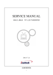
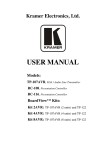
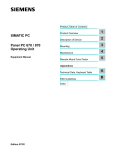
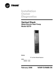
3 frame sizes, 1 family
The new range of air circuit breakers includes one family:
NA1 series in three frame sizes, one with rated current from 400A to
2000A, another 2000A to 4000A and the other 4000A to 6300A.
NA1-2000
400A to 2000A
NA1-3200, 4000
NA1-6300
2000A to 4000A
4000A to 6300A
.1.
NA1 Air
Circuit Breaker
NA1 Air Circuit Breaker
11
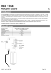
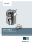
1
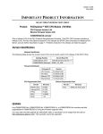
Drawout type
2
Fixed type
3
Intelligent controller
4
Operating mechanism
5
Auxiliary contact
6
Locking-device
7
Arcing chamber
8
Secondary connecting part
9
Wire-cable mechanical interlock
7
12
8
9
13
10
14
10 Connecting-rod type mechanical interlock
11 Shunt release
12 Closing electromagnet
1
13 Under-voltage release
14 Motor-driven energy-storage mechanism
15
15 Rotary handle
3
16 Fixed plate
4
5
2
16
6
.2.
3.
NA1 Air
Circuit Breaker
Fixed type breaker/switch-disconnector
1. Essentials of NA1
1.1 APPLICATION SCOPE
NA1 series air circuit breaker is suitable for the circuit of AC 50Hz/60Hz with rated service voltage 400V, 690V and rated service current up to
6300A. It is mainly used to distribute electric energy and protect circuits and power-supply equipment from over-load, under-voltage, short-circuit
and single-phase earthing. With intelligentized and selective protection functions, the breaker can improve the reliability of power supply, and avoid
unnecessary power failure. The breaker is applicable for power stations, factories, mines (for 690V) and modern high-buildings, especially for the
distribution system of intelligent building.
1.2 Standard: IEC/EN60947-2.
1.3 Certifications: CB, PCT, RCC, KEMA, SEMKO
2. Type Designation
2.1 Type Designation
N A 1-
Fixed plate for the fixed type breaker
/
Number of poles
Frame size rated current
Design number (enterprise)
Air circuit breaker
Enterprise Code
2.2 Environment conditions for operation
Environmental temperature
Temperature condition: -5 ~+40 ; the average value within 24h shall not exceed
+35 (Special situation excluded);
2.3 Elevation
Altitude of installation place shall not exceed 2000m.
Atmosphere condition
Relative humidity at +40 shall not exceed 50%. Higher humidity is permissible at lower temperature condition. When the highest monthly
average relative humidity is 90% in the humiddest month, the lowest monthly average temperature of this month is +25 . And consider the
influence of dew on product surface due to temperature changes.
Pollution grade: grade .
The breaker should be installed according to the requirements on the instruction manual. The vertical inclination degree shall not exceed 5 .
2.4 Note: Without the intelligent controller,the breaker functions as a switch-disconnector.
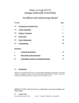
Fault-breaking indicator
reset button
Enclosure
Waking button
Energy storage &
release indicator
Breaking button
Breaking/making
indicator
Name plate
Structure for in and out
Rotary handle
Rotate out
Rotate in
3. Structure
Drawout type breaker and Fixed type breaker
Drawout type breaker/switch-disconnector
Under-voltage release
page 25
Shunt release
page 25
+
Drawer seat
=
Body
The breaker is composed of body and drawer base. Inserting the body into the drawer base,make it into drawout-type breaker.
.4.
Closing electromagnet
page 26
Auxiliary contact
page 27
Motor-driven energy
storage mechanism
page 26
Locking device
page 27
Intelligent controller
page 19
.5.
NA1 Air
Circuit Breaker
4. Installation and usage
4.1 Installation
4.1.1 Unload the breaker from the soleplate of package. If it is drawout type, firstly pull out the handle under the drawer-base of
breaker, and plug it into the hole on central part of plastic cover under the drawer-base crossbeam, anticlockwise turns the handle,
body will slowly slide along the outside of drawer-base. When the guide rod points to separated position and handle can't be
rotated any longer, pull out the handle and firmly grasp the aluminum handle on drawer-base, pull out the breaker body and
remove it form the base, then move the base from the soleplate and clean up the dirty things inside the drawer-base.
Possible positions
Mounting with vertical brackets
4.1.2 Check the insulation resistance with a 500V megger, resistance should not be less than 20M when ambient temperature is
20
5 and relative humidity is 50%~70%. Otherwise dry it.
4.1.3 Power supply
NA1 devices can be supplied either from the top or from the bottom without reduction in performance, in order to facilitate
connection when installed in a switchboard.
Mounting on rails
4.1.5 Partitions
Sufficient openings must be provided in partitions to ensure
good air circulation around the circuit breaker;Any partition
between upstream and downstream connections of the device
must be made of nonmagnetic material.
For high-currents, of 2500 A and upwards, the metal supports or
barriers in the immediate vicinity of a conductor must be made of
non-magnetic material A;Metal barriers through which a conductorBusbars
passes must not form a magnetic loop.
The mechanical connection must be exclude the
possibility of formation of a magnetic loop around a conductor
non magnetic material
A
A:non magnetic material
4.1.6 Busbar connections
The busbars should be suitably adjusted to ensure the connection points are positioned on the terminals before the
bolts are inserted B The connections are held by the supporter which is fixed to the framework of the switchboard, in this
way the circuit breaker terminals do not have to support its weight C. (This support should be placed close to the terminals).
4.1.4 Put the breaker (fixed-type) or drawer-base (drawout-type) into the installation-bracket, and make it fixed, directly connect the
cable wire of main circuit to the bus wire of fixed-type circuit breaker. Alternatively put breaker body onto the slideway of drawerbase. Plug the handle into installation hole, clockwise turns it until the under-part of drawer-base points at the connection position
and click sound is heard. It indicates that breaker body has been connected to its place, then connect the cable of main circuit to
drawer-base.Mounting the circuit-breaker
It is important to distribute the weight of the device uniformily over a rigid mounting surface such as rails or a base plate.
This mounting plane should be perfectly flat (tolerance on support flatness: 2 mm).This eliminates any risk of deformation which
could interfere with correct operation of the circuit breaker.
NA1 devices can also be mounted on a vertical plane using the special brackets.
B
C
B
A
.6.
.7.
NA1 Air
Circuit Breaker
4.1.7 Main circuit adopts cable connection
Users should not apply too strong mechanical strength on the terminals of Air Circuit Breaker. Extend the bus-bar of circuit
breaker with connecting bus-bar, position the wiring piece of cable before inserting bolts; the cable should be fixed on the
frame of distributing cabinet firmly.
1 2
3
4
1.Both main circuit and control
circuit are connected.
2.Normal application conditions
Drawout position
Disconnected position
1.The main circuit is disconnected,
and the control circuit is connected.
2.Test application conditions.
Neither the main circuit
nor the control circuit is connected.
Main body is out
of the drawer seat.
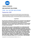
5. Dimensions and connection
1
2
3
4
5
breaker terminal
busbar
bolt
washer
nut
NA1-2000 Drawout-type
45(Disconnected position)
448(4-pole)
a
353(3-pole)
a
360(4-pole)
5
258
175
11
2-11
175
187.5
421
292
465
17
14
55
70
37
42.5
92
97
23
10
439
112
Examples
265(3-pole)
4.1.8 Clamping
Correct clamping of busbars depends on the tightening torques
used for the nuts and bolts,etc. Over-tightening may have the
same consequences as under-tightening.
For connecting busbars to the circuit breaker, the tightening torques
to be used are shown in the table below.These values are for use
with copper busbars and steel nuts and bolts, class 8.8.
Test position
Connected position
33
Right &outer side of breaker
375(3-pole)
11Nm
M10
Installing bolts of Air Circuit Breaker
45Nm
M12
Connection terminals
50Nm
11-
344
14
37.5
302
378
155
172
5
15.5 Installation panel
Opening hole on panel
95
95
Horizontal
N-pole
In A
630
800~1600
2000
a mm
10
15
20
40
Preferred tightening torque
95
Right & outer
side of breaker
13
115
Application
Screws for secondary terminals
M4
302
8-
60
28
17
Preferred tightening torque for NA1's tightening components
Type of screw
N-pole
47 20
268
21.5
470(4-pole)
32-
28
60
13
95
95
95
Vertical
.8.
.9.
NA1 Air
Circuit Breaker
NA1-2000 Fixed-type
15
72
21
21
150
290
11
389
115
115
Horizontal
11
211
13
11
181
13
13
a
11
258
112
115
95
Horizontal
16-
86
40
60
95
N-pole
55
42
258
13
60
359
352
a
8-
50
290
a mm
In A
2000~2500 20
30
3200
378(3-pole)
60
28
493(4-pole)
a
402
335
55
112
N-pole
95
150
50
Min18
402
292
a
a mm
10
15
20
In A
630
800~1600
2000
318(3-pole)
40
Zero arcing covering:
ferreous material
413(4-pole)
335
Min18
17
Zero arcing covering:
ferreous material
NA1-3200 Fixed type
400(3-pole)
340(3-pole)
515(4-pole)
4-
435(4-pole)
12
12
Right &outer side
of breaker
8- 5
Installation hole on
right side of breaker
2
342.2
Installation hole on
Right &outer side
of breaker
515(4-pole)
28
60
13
95
Installation panel
40
115
311
15
28.5
400(3-pole)
40
32-
N-pole
362
115
28.5
Installation hole on
340(4-pole)
435(4-pole)
N-pole
17
300
269
311.2
269
150
150
4-
32-
8- 5
Installation hole on
right side of breaker
404
95
115
Installation panel
95
40
86
13
2
115
Opening hole on panel
Vertical
Opening hole on panel
NA1-3200 Drawerout-type
NA1-4000 Drawerout-type(3-pole)
45(Disconnected position)
45(Disconnected position)
70
125
10
97
175
Horizontal
217.5
352
494
435(3-pole)
37
352
439
42.5
25
92
125
50
115
217.5
491
536
258
13
112
16-
100
50
100
258
37
70
42.5
439
a
112
92
23
175
N-pole
30
A(mm)
In A
2000~2500 20
30
3200
413(3-pole)
97
528
528(4-pole)
a
10
115
Vertical
550
11-
5
404
15.5
Right&outer
side of breaker
Installation panel
32-
115
125
Vertical
125
11175
12202
5
404
40
20
103
155
302
378
268
17
14
40
100
13
362
47 20
440
115
302
155
202
Opening hole on panel
.10.
2-11
55
33
40
14
175
11
N-pole
17
17
Right &outer side of breaker
362
378
268
2-11
47 20
440(4-pole)
11
55
325(3-pole)
21.5
21.5
550(4-pole)
13
50
140
Right&outer
side of breaker
15.5
197.5
197.5
Installation panel
33
Right & outer
side of breaker
Opening hole on panel
.11.
NA1 Air
Circuit Breaker
NA1-6300 (In
4000A
5000A) Drawer type
45(Disconnected position)
Secondary circuit wiring and maintenance
Over-current release
Main circuit
Emergent
disconnection
motor
driven
break
auxiliary switch
motor
driven
close
928(4-pole)
30
813(3-pole)
258
42.5
37
Open
70
92
Energy storage
Close
449
112
Failure
10
97
175
217.5
494
352
FU
835(3-pole)
950(4-pole)
17
14
175
11-
155
20
155
210
15
Power
40
103
378
362
302
135
268
2-11
28-
47 20
818(4-pole)
11
55
703(3-pole)
21.5
N-pole)
Processing
unit
55
202
5
404
33
15.5
247
182
Right & outer
side of breaker
Intelligent Controller
247
FU
Installation panel
Right &outer side of breaker
Opening hole on panel
~_ 110V
~_ 220V
~380V
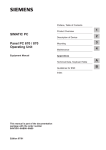
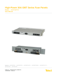
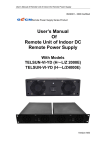
Intelligent release power("1"connect positive pole,and"2"connect negative pole for direct current)
SB1 Shunt button
NA1-6300(In
6300A) Drawerout-type(3-pole)
SB2 Under-voltage button
SB3 Making button
Q Under-voltage release or under-voltage time-delay release
X Closing electromagnet
M Energy-storage motor
SA Travel switch
F Shunt release
XT Connection terminal
45(Disconnected position)
10
97
42.5
449
Note: If control voltage of Q, F, X is different from each other, they can be connected to different power. If model ST intelligent
release is DC, it must pass through U1 and U2 before directly connected to terminal 1 or 2.Circuit explanation for signal
output
a.Broken-line parts shall be provided by customers.
b.Terminals 6# ~7# can output NC (normal close) contact if that is required by users.
c.Terminal 35# can be directly connected to power (automatic pre-storing energy), alternatively connect power after connecting NO
button (manual-controlled pre-storing energy).
In order to avoid the damage to shunt release and closing electromagnet, one group of NO (shunt release) or NC (closing
electromagnet) contact should be separately connected to the control circuit.
Wiring diagram of communication-type intelligent controller
70
92
37
112
258
30
928
217.5
175
352
494
2-11
17
55
14
11175
Right & outer
side of breaker
.12.
33
24-
15
5
20
80
337
202
260
40
103
378
155
362
47 20
818
11
180
302
268
21.5
950
337
Right & outer
side of breaker
15.5
404
Installation panel
Opening hole on panel
.13.
NA1 Air
Circuit Breaker
L1
N
PE
1
2
QF: Circuit breaker NA11 2 3 4 5
ST Power Supply Modular IV
L N
L N PE
+ + + + -
To T03 busbar
Profibus-DP
12 13
ST-DP
Special connecting wire
Modbus-RTV
Red
6
8
10
PE Un U1 U2 U3
Transformer
connected
Green
12
14
16
YEHL: Signal indicator AD11-25~230V Yellow
GNHL: Signal indicator AD11-25~230V Green
18
20
22
24
26
28
RDHL: Signal indicator AD11-25~230V Red
D11D12D13
DO24V
DO24VCOM
ST201
DO3
DO1
12 13 14 15 16 17 18 19
to the incoming-line side
4
SB1~2: Button LA18-22 Each one for red and green
18 19
+ + 1 2 3 4 5 6 7 8 9 10 11
Device
2
14 15 16 17
FU1~2: Fuse RT14-20/10A
30
32
34
36
38
40
Number inside the broken-line circle, is the terminal number on terminal block of NA1 body
(Na1 Inner components)
42
44
Q: Under-voltage coil~400V
46
F: Shunt coil~230V
X: Closing electromagnetic~230V
M: Energy-storage motor~230V
Q
F
X
SA: Motor limit switch
M
1
3
5
7
9
11
13
15
17
19
21
23
25
27
29
31
33
Dual receiving-circuit auto-switching operation circuit
35
37
39
41
43
45
Energystorage
main
circuit
Intelligent controller with auxiliary functions
Undervoltage Shunt Closing energystorage
release electromagnet indication
release
47
Open
energystorage
motor
Close
auxiliary switch
L1,L2,L3
1#, 2#: Auxiliary power input
12#: Overload pre-alarm signal output
13#: M is wireless, H is open signal
14#: M is short-circuit tripping signal, H is closing signal
15#: M indicates long time-delay tripping signal, H is wireless 16#: Earthing tripping or alarm signal output or leakage alarm signal
17#: Unloading output of No1 signal
18#: Unloading output of No.2 signal
19#: output common line of contacts
20#: Self-diagnose alarm signal output
21#: Fault tripping signal output
22#, 23#, 24#: A,B,C Three-phase power input terminal
ST-DP: DP Transformer device
L1,L2,L3
40 39
43 42
1QF
2QF
Manual
Stop Auto
34
Single receiving-circuit operation circuit
L3
L1
27
Q
139
29
F
103
SB2
107
31
X
34
L11,L12,L13
TA1
SA
SA
TA2
TA3
1
.14.
30
32
35
45 105 GN
46
Processing unit
M
1
IYE
45 105
IGN
47 135
IRD
2
processing unit
33 171 YE
M
35 171
28
201
SB1
33
SA
46
2TA1 2TA2 2TA3
FU2
QF
101
QF
L11,L12,L13
L11,L12,L13
1TA1 1TA2 1TA3
FU1
L1,L2,L3
N
SA
40
1QF
39 237 209 43
1QF
42 202
102
1QF, 2QF: Circuit breaker NA1-
(NA1 Inner components)
1FU1~2: Fuse RT14-20/10A
Q: Under-voltage coil~400V
1SB1~2: Button LA18-22 Each one for red and green
F: Shunt coil~230V
1SA: Change-over switch LW12-16/4.0081.1
X: Closing electromagnet~230V
1KT: Time-delay relay JS14A~230V
M: Energy-storage motor~230V
1YEHL: Signal indicator AD11-25~230V Yellow
SA: Motor limit switch
1GNHL: Signal indicator AD11-25~230V Green
47 135 RD
1RDHL: Signal indicator AD11-25~230V Red
2
number on terminal block of NA1 body
Number inside the broken-line circle, is the terminal
.15.
NA1 Air
Circuit Breaker
5.1 Wiring the secondary circuit according to electric principle diagram.
Note:Bolts, nuts, gaskets shouldn't be left inside the drawer seat to avoid being blocked.
5.2 Operation
Check the rated voltage of the following components whether conforms to the power voltage . Such as under voltage release,
shunt release, closing electromagnet, motor-driven mechanism and intelligent controller
5.3 Maintenance
Check the technical parameters in time or add some lubricating oil.,etc.This breaker structure is arranged vertically
and modularized composition with each functioncell separated,which make the maintenance easy. It has compact structure,
reliable operation and strong free maintenance capability.Please check the technical parameters on the nameplate in accordance
with the requirements of order before installation
6. Regular malfunction and solutions
Reasons analysis
Fault description
Over load tripping
(IL indicator flashing)
(
1. Check the breaking current value and operation time of intelligent release.
Short circuit tripping
2. Exclude the short circuit fault if it happens
Is or Ii indicator flashing) 3. Check the setting value of intelligent release
4. Check the normal state of breaker
5. Press the reset button to reclose the breaker
Tripping of
circuit breaker
Secondary connecting part
Arcing chamber
Earthing fault tripping
(IG indicator flashing)
Main body
Drawer seat
Under-voltage release fault:
1. Rated working voltage is
less than 70%Ue
2. Fault of control unit
Mechanical interlock acting
Intelligent release don't reset
(panel is raised)
Handle
Maintenance method
1. Check the breaking current value and operation time of intelligent release.
2. Analyze the load and electric network, exclude the overload if it happens.
3. Match the actual operating current with long time-delay current setting value.
4. Press the reset button to reclose the breaker
1. Check the breaking current value and acting time of intelligent release.
2. Exclude the earthing fault if that happens.
3. Match the fault current setting value with the actual protection.
4. Press the reset button to reclose the breaker.
1.Check the power is on or not
2.Check the power voltage of under-voltage release, it shouldn't be less
than 85%Ue.
3.Replace the control unit of under-voltage release
Check the working state of two circuit breakers fixed with mechanical interlock
Press the reset button to reclose the breaker
Slideway
Secondary circuit of drawerouttype breaker isn't connected
Making the secondary circuit power, the motor-driven mechanism can store energy automatically until hearing the click and energy
stored indicating on the panel. Otherwise press the storage handle for 6 times until hearing the click and the indicator display
energy stored And the closing operation can be realized either by closing electromagnet or manual button.
The breaker
can't be
closed
Manual energy-storage
Breaker hasn't stored energy
Mechanical interlock acting
leads to locking of breaker
Closing electromagnet:
1.Rated control voltage is
less than 85%Us;
2.Closing electromagnet
is damaged
Tripping after
closing the
circuit breaker
(Fault indicator
flashing)
Trippingimmediately:
1.Shortcircuitcurrentisclosed
2.Delaytrippingbecauseof
transientcurrentishighwhen
closing;
3.Overloadcurrentisclosed
Make the breaker to "making" position
("click" sound will be heard)
Check the secondary circuit:
1. Power voltage of motor shouldn't less than 85%Ue.
2. Check the storage mechanism, replace it if necessary.
Check the working state of two circuit breakers
fixed with mechanical interlock
1. Power voltage of closing electromagnet
shouldn't less than 85%Us.
2. Replace the electromagnet.
1. Check the breaking current value and operation time of intelligent release;
2. Exclude the short circuit fault if it happens;
3. Exclude overload fault
4. Check the normal state of breaker
5. Modify the current setting value of intelligent release
6. Press the reset button to reclose the breaker
Shake with the manual energy-storage handle
up and down about six times to "click".
.16.
.17.
NA1 Air
Circuit Breaker
Fault description
Reasons analysis
Circuit breaker
can't be opened
Intelligent controller is the core part of circuit breaker, it is classified into two types: standard and communication.
1. Check the mechanism, if there is fault happened.
Standard type
Protection function
Communication type
Inverse-time protection for overload long-delay
The breaker can't be opened by motor
remotely
1. There is fault with mechanical
operating mechanism
2. Power voltage of shunt
release is less than 70%Us;
3. Shunt release is damaged
Manual storage can't be realized
Circuit breaker
can't store energy
7. Intelligent controller
Maintenance method
The breaker can't be opened manually
1. There is fault with mechanical operating
mechanism
Inverse-time protection or definite time-delay
1. Check the mechanism, if there is fault happened.
2. Check the Power voltage of shunt release is less
than 70%Us or not
3. Replace shunt release
protection for short-circuit short-delay
Instantaneous short-circuit protection
Protection of neutral line or earthing faults
Over-voltage protection
Mechanical fault with the energy-storage device
Motor storage can't be realized
1. Power voltage of motor energy-stored device shouldn't less
1.Power voltage of motor
than 85%Us
energy-stored device is less than 85%Us;
2. Mechanical fault with the energy-storage device
2.There is mechanical fault
with energy-storage device
Under-voltage protection
Over-frequency protection
Under-frequency protection
Protection of unbalanced voltage
Protection of phase sequence
Measuring function
Handle of drawerouttype circuit breaker
can't be drawn in or out
1. There is padlock at the "opening" position
1.Take away the padlock
2. Slideway or breaker body
2.Pull the slideway or breaker body into its position
isn't pulled into its position
Drawerout-type breaker
1.Handle isn't pulled out
can't be drawn out
2.Breaker is not totally at the
at the "opening"
"opening" position
position
Drawerout-type breaker
can't reach the
"making" position
No display on
intelligent release
panel
Measure of current
Measure of voltage
Measure of frequency
1.Pull out the handle
2.Keep the circuit breaker totally at
Measure of power factor
opening
position
Measure of power
Detection of phase sequence
1. Something drop into the drawer base,
and lock the mechanism or mechanism
1. Check and clean the drawer base, or contact with manufacturer
fault happens.
2. Match the body with relevant drawer base
2. Breaker body not match with the frame-size
rated current of drawer base
1. Release isn't connected
with power
2.There is fault with release
1.Check the power is connected or not
2.Cut off the power, then connect again. Otherwise contact
with manufacturer
Closing electromagnet:
1. Rated control voltage is less than 85%Us;
2. Electromagnet is damaged
1. Check the electromagnet power voltage shouldn't be less
than 85%Us.
2. Replace the closing electromagnet.
Measure of unbalanced rate of voltage
Measure of electric energy
Maintenance function
Test function
Inspecting and memorizing faults function
Self-diagnosis function
Equivalent of contactor
Recording historical parameter of power network
Others functions
Monitoring load function
Fault indicator still
flashing after pressing
the clear button
Fault happened with
intelligent release
Cut off the power, then connect again. Otherwise contact
with manufacturer
MCR ON/OFF function
Output of signal touch points function
Zone selectivity interlocking (ZSI) function
Communication function
Note:
.18.
means basic function,
means optional function.
.19.
NA1 Air
Circuit Breaker
7.1 Standard type (model M)
Model M
7.1.1 Basic functions:
a.Over-load long inverse time-delay protection
b.Short inverse time-delay or definite time-delay protection
c.Instantaneous protection
d.Earthing fault protection
e.Query function
f.Parameter setting function
g.Test function
7.1.2 Selective function:
a.load monitor function
b.making current release (MCR)
c.signal alarm function
details are in user manual
7.2 Communication type(Model H)
communication has one more function of communication than
the standard.
7.2.1 Basic functions:
a.Over-load long inverse time-delay protection
b.Short inverse time-delay or definite time-delay protection
c.Instantaneous protection
d.Earthing fault protection
e.Ampere-meter function
f.Self-check
g.Setting
h.Test
i.Monitoring with load
j.Display
7.2.2 selective functions
a.Voltage
b.Frequency
c.Power factor
d.Active power display
Refer to intelligent controller user manual for details.
.20.
Model M
Model H
1 Reset button: After the breaker trip by fault, the reset button should be pressed in order to
make it close again.
Otherwise, it won't be realized.
2 Display screen: It shows time and current value.
3 LED indicator: display all states and types.
4 Select key: Under normal operation state, shows the parameters of current, time or voltage of every phase.
5 Clean key: Press this key to make breaker normally operate after release's setting, test, fault or data check.
6 Set key: Check and set the current and time for protection characteristic. Press this key to circularly display each state
of breaker.
7 Trip or non-trip key: Used for release test function, when tested, the breaker is needed to be broken or not.
8 Fault check key: Press this key to display the last fault state and its fault current and time.
9 Save
key: Setting the current and time.
10 A/KA/S indicator: Indicate the unit of displayed value.
11 G
indicator: Indicate the displayed current is earthing fault current.
12 L1, L2, L3 indicator: L1, L2, L3 is the phase of displayed current, if MAX simultaneously shining with one
of L1,L2,L3, it shows the displayed phase's current is maximum among three phases.
13 Test indicator: it indicates the breaker is at the test state.
14 Trip indicator: Indicate the release sending out tripping signal.
15 Indicator flashing shows the earthing-fault process state, if shining with trip
light, shows it has tripped.
16 Indicator flashing shows the fault process state of instantaneous short-circuit, if shining with trip light, shows it
has tripped.
17 Indicator flashing shows the fault process state of short-circuit short time-delay, if shining with trip light, shows it
has tripped.
18 Indicator flashing shows the fault process state of overload long time-delay, if shining with trip light, shows it has
tripped.
19 Set state of earthing fault protection, set current is displayed if the light flashs.
20 Set state of earthing fault protection, set time is displayed if the light flashs.
21 Set state of long time-delay protection, set current is displayed if the light flashs.
22 Set state of long time-delay protection, set time is displayed if the light flashs.
23 Set state of short time-delay protection, set current is displayed if the light flashs.
24 Set state of instantaneous protection, set time is displayed if the light flashs.
25 Set state of short time-delay protection, set time is displayed if the light flashs.
26 Load1 , load2 indicator means two current settings are monitored with load.
27 the indicator flashs once means the set value has been saved.
.21.
NA1 Air
Circuit Breaker
7.3 Protecting manners for earthing faults
a. NA1 three-pole circuit breaker is used in three-phase three-wire system without
additional external-connection mutual-inductor.
Protective signal of earthing faults only adopts vector summation of three-phase current.
Characteristic of protection is definite time-delay protection.
Model H
1 Reset button: After the breaker trip by fault, the reset button should be pressed in order to make it close again. Otherwise, it won't be
realized.
2 Display screen: It shows time, current and voltage., etc.
3 LED indicator: display all states and types.
4 Function key: Press this key to select the function to be operated.
5
key: Check and set the current and time for protection characteristic. Press this key to circularly display each state of breaker.
6 Confirm key: After selecting the function or parameter, press this key to confirm.
7 Return key: After the function is operated, press this key to choose another function or set parameter.
8 Programme interface: Original program of release, compiling of parameter and modification input.
9 Communication light: This light flashing if release at the communication state.
10 Position lock: Indicates the state of release if communication function is operated.
Note: Conform to the communication protocol of Modbus or Profibus + DP.
Characteristic of intellingent controller
Current
mutualinductor L1
Transformer
L2
L3
Intelligent
controller
Current
mutualinductor L1
Transformer
b. NA1 four-pole circuit breaker is used in three-phase four-wire system
Protective signal of earthing faults adopts vector summation of three-phase current
and N-pole current.
Characteristic of protection is definite time-delay protection.
L2
L3
N
Intelligent
controller
c. NA1 three-pole circuit breaker is used in three-phase four-wire system
Current mutual-inductor connected with neutral-pole N outside and the mutual-inductor
inside circuit breaker are used for protection of earthing faults after combining (connected to
No. 25 and No. 26 of terminals). Neutral-pole mutual-inductor is provided together with the
circuit breaker.
Protective signal of earthing faults adopts vector summation of three-phase current and N-pole
current.
Characteristic of protection is definite time-delay protection.
d. External-connection mutual-inductor is used for protection of earthing faults through
detecting the current of earthing-cable directly (connected to No. 25 and No. 26 of
terminals), i.e. it is earth-current type which is applicable for earthing of transformer, and
here the longest distance between mutual-inductor and circuit breaker is no more than 10m.
Characteristic of protection is definite time-delay protection.
Current
mutualinductor
Transformer
L1
L2
L3
N
Intelligent
controller
Current
mutualinductor
Transformer
L1
L2
L3
N
Intelligent
controller
PE
e. External-connection mutual-inductor is used for protection of earthing faults (electric leakage) through detecting current by means of
zero-sequence sampling (connected to No. 25 and No. 26 terminals), i.e. it is external-connection mutual-inductor, residual-current
type.
The sensitivity of this type is very high, and the current of earthing faults is not related with rated current of the circuit breaker. It is
suitable for the earthing protection with smaller earthing current. The external-connection mutual-inductor will be prepared by the user.
Characteristic of protection is definite time-delay protection
Transformer
Current
mutualinductor
Transformer
L1
L2
L3
N
Current
mutualinductor
L1
L2
L3
PE
Intelligent
controller
.22.
Intelligent
controller
.23.
NA1 Air
Circuit Breaker
8. Choosing manual
Type
NA1-2000
9. Accessories
9.1 Shunt release (electrifying time is no more than 1s/time, and electrifying frequency is no more than 5 times/ min.)
Except manual-operated to directly break the circuit breaker for special products It can be remote-operated to break the circuit breaker
Characteristic
Rated control power voltage Us (V)
Icu=80kA 400V
Rated service breaking capacity (Ics)
Ics=50kA 400V
40kA 690V
Rated short-time withstand current (Icw)
Icw=50kA 400V
40kA 690V
Rated current
400
In (A)
630
800
50kA 690V
1000
300VA
Power loss
1600
2000
Forbid making the power for long time to avoid being damaged.
1000
Rated insulation voltage Ui (V)
50%In, 100%In
Rated current of N-pole (A)
23~32
Break time (ms)
Standard type (M)
Communication type (H)
Electrical life
1000
Non-maintenance 2500
Mechanical life
Maintenance
9.2 Under-voltage release (power supply must be connected before circuit breaker's connection)
Users can select it or not up to your needs.Under-voltage release is used to break circuit breaker and protect the equipment
(such as motor) when under-voltage or voltage-failure happens. or automatically break the under-voltage circuit of power supply
system, improves the reliability and safety (such as dualcircuit). It is classified into instantaneous and time-delay type.
Delay-time of under-voltage time-delay release is classified into fourtypesof1s,3s,5sand 7s,andtheaccuracy is 15%.
Within 1/2 time-delay range, circuit breaker does not break when power voltage recovers and exceeds 85%Ue.
10000
Horizontal, Vertical
Connection pattern
Type
NA1-3200
NA1-4000
NA1-6300
Characteristic
Rated control power voltage Us (V)
Short-circuit breaking capacity
AC400, 230, 127
Work voltage (V)
(0.35~0.7) Ue
Reliable breaking voltage (V)
(0.85~1.1) Ue
Reliable non-breaking voltage (V)
Rated ultimate breaking capacity (Icu)
Icu=100kA 400V
65kA 690V
Icu=120kA 400V
Rated service breaking capacity (Ics)
Ics=80kA 400V
65kA 690V
Ics=100kA 400V
75kA 690V
Rated short-time withstand current (Icw)
Icw=80kA 400V
50kA 690V
Icw=100kA 400V
75kA 690V
Rated current
In (A)
Number of poles
Rated voltage Ue (V)
2000
2500
3200
3, 4
4000
3
400, 690
4000
Close the circuit before operating the circuit breaker
3
1000
1000
50%In, 100%In
23~32
23~32
Standard type (M)
Communication type (H)
Electrical life
Mechanical life
Connection pattern
.24.
0.35Ue
48VA (W)
6300
3, 4
50%In, 100%In
Operation
performance
Power loss
DC220, 110
400, 690
Rated current of N-pole IN (A)
Fixed disconnection time (ms)
85kA 690V
5000
Rated insulation voltage Ui (V)
Intelligent
controller
40W
30ms~50ms
Breaking time
400, 690
Rated voltage Ue (V)
Operation
performance
1250
DC220, 110
(0.7~1.1) Us
3, 4
Number of poles
Intelligent
controller
AC400, 230, 127
Working voltage (V)
Rated ultimate breaking capacity (Icu)
500
500
Non-maintenance 2500
Non-maintenance 2500
Maintenance
Maintenance
10000
Horizontal, Vertical
10000
Horizontal, Vertical
.25.
NA1 Air
Circuit Breaker
9.3 Closing electromagnet (electrifying time is no more than 1s/time, and electrifying frequency is no more than 5 times/ min.)
After the motor finishes energy storage, closing electromagnet can instantly release spring-force of operation mechanism,
and quickly close the circuit breaker.
Characteristic
Rated control power voltage Us (V)
AC400, 230, 127
Work voltage (V)
DC220, 110
(0.85~1.1) Us
Power loss
300VA
Energy-storage time
40W
Less than 70ms
Forbid making the power for long time to avoid being damaged.
9.6 Off position locking device
Off position locking device willmakethebreakingbuttonlockedatthepressedposition, and the
breaker can't be closed at this moment.
When drawer-type breaker at the breaking position, pull out the lock-rod and lock the breaker
by padlock, after that circuit breaker can't reach "test" or "making" position (Padlock is prepared by
users), locks and keys will beprovided by us. Separate lock and key is matched with one set of circuit
breaker. Two same locks and keys are matched with two circuit breakers.
three same locks and two same keys are matched with three circuit breakers.
9.7 Mechanical interlock
It can realize the interlock of two horizontal or vertical-installed three-pole or four-pole drawer-type or fixed-type circuit breakers.
9.4 Motor-driven energy-storage mechanism (electrifying time is no more than 5s/time, and electrifying frequency is no more
than 3 times/ min.) With automatic re-storing energy function, which is convenient for switching duplicate power supply.
Characteristic
Rated control power voltage Us (V)
AC400, 230
Work voltage (V)
(0.85~1.1) Us
Power loss
85W/110W/150W
Storing-energy time
2m(max)
DC220, 110
192W
Less than 5s
Forbid making the power for long time to avoid being damaged.
9.8 Connecting-rod type mechanical interlock
Three vertical-installed three-pole or four-pole drawer-type or fixed-type circuit breakers realize the interlockbetweenonebreakerwith
another two different-state breakers.
10. Recommendation for user's connecting bus-bar
Inm(A)
In(A)
Thickness(mm)
Busbar Width(mm)
9.5 Auxiliary contact
Standard model:4-NO (normal open) and 4-NC (normal close) Special models:3-NO & 5-NC, 5-NO & 3-NC, 6-NO & 2-NC,
2-NO & 6-NC. Rated value
Rated voltage (V)
Conventional free-air thermal current Ith (A)
NA1-3200
NA1-4000
NA1-6300
3200 4000/3P4000/4P 4000
5000
6300
800
1000
1250
1600
2000
2000
2500
2900
5
6
6
8
8
8
8
10
10
10
10
10
10
10
10
50
60
80
80
100
100
100
100
100
100
100
100
100
100
100
2
2
2
2
2
2
2
2
4
4
4
4
4
6
6
Note: the specifications in the table is obtained as the ambient temperature of air circuit breaker is 40 , with open installation; this is
in compliance with the specification of copper busbars adopted under the heating conditions regulated in IEC/EN60947-2.
Rated control capacity
AC230
6
300VA
AC400
6
300VA
DC220
6
60W
.26.
Number
NA1-2000
630
.27.
NA1 Air
Circuit Breaker
11. Power loss
Drawer type
Fixed type
NA1-6300
3200 4000/3P 4000/4P 4000
630
800
1000
1250
1600
2000
2000
2500
5000
6300
70
110
172
268
440
530
384
600
737
921
900
575
898
1426
34.4
50
78
122
200
262
200
312
307
-
-
-
-
-
Rated current
Power loss
(W)
NA1-4000
2
12. A S curve
I 2t
A2s 106
741
2000
1900
1800
In=2000A
1700
1600
1500
1400
1300
1200
1100
1000
900
800
700
600
500
400
In=1600A
40
341
5000
4800
4600
A
In(A)
NA1-3200
In=1250A
Rated current
NA1-2000
A
Inm(A)
In=1000A
In=800A
In=630A
45
50
55
60
65
70
NA1-2000
40
60
80
100
120 Is kA
A
20
Rated current
13. Derating usage
IEC/EN60947-2
.28.
Environmental
temperature
In=3200A
In=2500A
In=2000A
45
50
55
60
65
70
NA1-3200, NA1-4000
7000
6800
6600
Is: prospective symmetrical current(of an a.c. circuit)
Standard
40
In=4000A
Environmental temperature
Environmental temperature
200
190
180
170
160
150
140
130
120
110
100
90
80
70
60
50
40
30
20
10
4400
4200
4000
3800
3600
3400
3200
3000
2800
2600
2400
2200
2000
1800
NA1-3200
NA1-4000
NA1-2000
NA1-6300
40
630
800
1000 1250
1600 2000
2000 2500 3200
4000 4000 5000 6300
45
630
800
1000 1250
1600 1900
2000 2400 3000
3800 4000 5000 6000
50
630
800
1000 1250
1500 1900
2000 2300 3000
3600 4000 5000 5600
55
630
800
1000 1200
1500 1800
2000 2200 2800
3400 4000 4800 5400
60
610
800
1000 1150
1300 1700
2000 2200 2800
3200 4000 4800 5200
65
610
800
1000 1150
1300 1650
2000 2200 2600
3200 4000 4800 5100
6400
6200
6000
5800
5600
5400
5200
5000
4800
4600
4400
4200
4000
3800
40
In=6300A
In=5000A
In=4000A
45
50
55
60
65
70
Environmental temperature
NA1-6300
.29.
NA1 Air
Circuit Breaker
14. Coordination recommendations
Capacity of transformer
(kVA) & parallelly
connected number
Rated current
of transformer
In(A)
Short circuit current
of main circuit
(kA)
Breaking capacity of
air circuit breaker for
main circuit (kA)
Type of air circuit
breaker for
main circuit
1
250
360
9
9
NA1-1000-400
2
250
360
9
9
NA1-1000-400
3
250
360
9
18.5
NA1-1000-400
1
315
455
11.4
11.4
NA1-1000-630
2
315
455
11.4
11.4
NA1-1000-630
3
315
455
11.4
22.7
NA1-1000-630
1
400
578
14.4
14.4
NA1-1000-630
2
400
578
14.4
14.4
NA1-1000-630
3
400
578
14.4
28.8
NA1-1000-630
1
500
722
18
18
NA1-1000-800
2
500
722
18
18
NA1-1000-800
3
500
722
18
36.1
NA1-1000-800
1
630
910
22.7
22.7
NA1-1000-1000
2
630
910
22.7
22.7
NA1-1000-1000
3
630
910
22.7
44.5
NA1-2000-1000
1
800
1154
19.3
19.3
NA1-2000-1250
2
800
1154
19.3
19.3
NA1-2000-1250
3
800
1154
19.3
38.5
NA1-2000-1250
1
1000
1444
24
24
NA1-2000-1600
2
1000
1444
24
24
NA1-2000-1600
3
1000
1444
24
48.1
NA1-2000-1600
1
1250
1805
30
30
NA1-2000-2000
2
1250
1805
30
30
NA1-2000-2000
3
1250
1805
30
60.1
NA1-2000-2000
1
1600
2310
36.5
36.5
NA1-3200-2500
2
1600
2310
36.5
36.5
NA1-3200-2500
3
1600
2310
36.5
73
NA1-3200-2500
1
2000
2887
48.2
48.2
NA1-3200-3200
2
2000
2887
48.2
48.2
NA1-3200-3200
3
2000
2887
48.2
96.3
NA1-3200-3200
1
2500
3608
60
60
NA1-4000-4000
2
2500
3608
60
60
NA1-4000-4000
1
3150
4550
75.8
75.8
NA1-6300-5000
2
3150
4550
75.8
75.8
NA1-6300-5000
.30.
Number and area of the
busbar for main circuit
(n W T)
Breaking capacity of
air circuit breaker
for branch circuit (kA)
240mm 2
18.5
Air circuit breaker
for branch circuit
9
NA1, NM8
27.5
11.4
300mm 2
22.7
NA1, NM8
34.1
14.4
30
10
28.8
NA1, NM8
43.2
18
2
40
5
36.1
NA1, NM8
54.1
22.7
2
50
5
44.5
NA1, NM8
67.2
19.3
3
50
5
38.5
NA1, NM8
57.8
24
2
60
10
48.1
NA1, NM8
72.1
30
2
80
10
60.1
NA1, NM8
90.1
36.5
2
100
10
73
NA1, NM8
109.5
48.2
2
120
10
96.3
NA1, NM8
144.5
2
(2
80
10)
60
NA1, NM8
120
2
(2
120
10)
75.8
NA1, NM8
151.6
.31.
NA1 Air
Circuit Breaker
15. Selectivity protection
15.1 Selective protection between NM8 and NA1
NA1-2000
Circuit breaker
Downstream
Upstream
NA1-3200
Rated
current (A)
400
630
800
1000
1250
Default setting ratings
of short time-delay 8In (kA)
3.2
5.04
6.4
8
Setting
range (kA)
0.4~6
0.63 9.45
0.8~12
1~15
1600
NA1-6300
NA1-4000
2000
2000
2500
3200
3200
4000
4000
5000
6300
10
16
16
20
25.6
25.6
32
32
40
50.4
1.25~18.75
2~30
2~30
2.5~37.7
3.2~48
3.2~48
4~60
4~60
5~75
6.3~94.5
Delayed tripping
time (s)
0.1, 0.2, 0.3, 0.4
0.1, 0.2, 0.3, 0.4
Returnable time
0.06, 0.14, 0.23, 0.35
0.06, 0.14, 0.23, 0.35
Instantaneous
Rated
Frame size
rated currentcurrent (A) setting ratings (kA)
16
20
25
32
NM8-125
NM8S-125
40
50
63
80
100
125
100
NM8-250
NM8S-250
160
200
250
.32.
0.16
0.4~6
0.63~9.45
0.8~12
1~15
1.25~18.75
1.6~24
2~30
2~30
2.5~37.7
3.2~48
3.2~48
4~60
4~60
5~75
6.3~94.5
0.19(motor)
0.4~6
0.63~9.45
0.8~12
1~15
1.25~18.75
1.6~24
2~30
2~30
2.5~37.7
3.2~48
3.2~48
4~60
4~60
5~75
6.3~94.5
0.2
0.4~6
0.63~9.45
0.8~12
1~15
1.25~18.75
1.6~24
2~30
2~30
2.5~37.7
3.2~48
3.2~48
4~60
4~60
5~75
6.3~94.5
0.24(motor)
0.4~6
0.63~9.45
0.8~12
1~15
1.25~18.75
1.6~24
2~30
2~30
2.5~37.7
3.2~48
3.2~48
4~60
4~60
5~75
6.3~94.5
0.25
0.4~6
0.63~9.45
0.8~12
1~15
1.25~18.75
1.6~24
2~30
2~30
2.5~37.7
3.2~48
3.2~48
4~60
4~60
5~75
6.3~94.5
0.30(motor)
0.414~6
0.63~9.45
0.8~12
1~15
1.25~18.75
1.6~24
2~30
2~30
2.5~37.7
3.2~48
3.2~48
4~60
4~60
5~75
6.3~94.5
0.32
0.4416~6 0.63~9.45
0.8~12
1~15
1.25~18.75
1.6~24
2~30
2~30
2.5~37.7
3.2~48
3.2~48
4~60
4~60
5~75
6.3~94.5
0.38(motor)
0.5224~6 0.63~9.45
0.8~12
1~15
1.25~18.75
1.6~24
2~30
2~30
2.5~37.7
3.2~48
3.2~48
4~60
4~60
5~75
6.3~94.5
0.552~6
0.8~12
1~15
1.25~18.75
1.6~24
2~30
2~30
2.5~37.7
3.2~48
3.2~48
4~60
4~60
5~75
6.3~94.5
0.8~12
1~15
1.25~18.75
1.6~24
2~30
2~30
2.5~37.7
3.2~48
3.2~48
4~60
4~60
5~75
6.3~94.5
0.8~12
1~15
1.25~18.75
1.6~24
2~30
2~30
2.5~37.7
3.2~48
3.2~48
4~60
4~60
5~75
6.3~94.5
0.40
0.48(motor)
0.50
0.63~9.45
0.6624~6 0.6624~9.45
0.69~6
0.69~9.45
0.60(motor)
0.828~6 0.828~9.45 0.828~12
1~15
1.25~18.75
1.6~24
2~30
2~30
2.5~37.7
3.2~48
3.2~48
4~60
4 60
5~75
6.3~94.5
0.63
0.8694~6 0.8694~9.45 0.8694~12
1~15
1.25~18.75
1.6~24
2~30
2~30
2.5~37.7
3.2~48
3.2~48
4~60
4 60
5~75
6.3~94.5
0.75(motor)
1.035~6 1.035~9.45 1.035~12
1.035~15 1.25~18.75
1.6~24
2~30
2~30
2.5~37.7
3.2~48
3.2~48
4~60
4 60
5~75
6.3~94.5
0.80
1.104~6 1.104~9.45 1.104~12
1.104~15 1.25~18.75
1.6~24
2~30
2~30
2.5~37.7
3.2~48
3.2~48
4~60
4 60
5~75
6.3~94.5
0.96(motor)
1.325~6 1.325~9.45 1.325~12
1.325~15 1.325~18.75
1.6~24
2~30
2~30
2.5~37.7
3.2~48
3.2~48
4~60
4 60
5~75
6.3~94.5
1.38~6
1.38~12
1.38~15 1.38~18.75
1.6~24
2~30
2~30
2.5~37.7
3.2~48
3.2~48
4~60
4 60
5~75
6.3~94.5
1.20(motor)
1.656~6 1.656~9.45 1.656~12
1.656~15 1.656~18.75
1.656~24
2~30
2~30
2.5~37.7
3.2~48
3.2~48
4~60
4 60
5~75
6.3~94.5
1.25
1.725 ~6 1.725~9.45 1.725~12
1.725~15 1.725~18.75
1.725~24
1.725~30
1.725~30
1.725~37.7
1.725~48
1.725~48
1.725~60
1.725~60
1.725~75
1.725~94.5
1.0
1.38~9.45
1.5(motor)
2.07~6
2.07~9.45
2.07~12
2.07~15 2.07~18.75
2.07~24
2.07~30
2.07~30
2.07~37.7
2.07~48
2.07~48
2.07~60
2.07~60
2.07~75
2.07~94.5
1.0
1.38~6
1.38~9.45
1.38~12
1.38~15 1.38~18.75
1.6~24
2~30
2~30
2.5~37.7
3.2~48
3.2~48
4~60
4 60
5~75
6.3~94.5
1.2(motor)
1.656~6 1.656~9.45 1.656~12
1.656~15 1.656~18.75
1.656~24
2~30
2~30
2.5~37.7
3.2~48
3.2~48
4~60
4 60
5~75
6.3~94.5
1.6
2.208~6 2.208~9.45 2.208~12
2.208~15 2.208~18.75
2.208~24
2.208~30
2.208~30
2.5~37.7
3.2~48
3.2~48
4~60
4~60
5~75
6.3~94.5
1.92(motor)
2.65~6
2.65~9.45
2.65~12
2.65~15 2.65~18.75
2.65~24
2.65~30
2.65~30
2.65~37.7
3.2~48
3.2~48
4~60
4~60
5~75
6.3~94.5
2.0
2.76~6
2.76~9.45
2.76~12
2.76~15 2.76~18.75
2.76~24
2.76~30
2.76~30
2.76~37.7
3.2~48
3.2~48
4~60
4~60
5~75
6.3~94.5
3.312~6 3.312~9.45 3.312~12
3.312~15 3.312~18.75
3.312~24
3.312~30
3.312~30
3.312~37.7
3.312~48
3.312~48
4~60
4~60
5~75
6.3~94.5
2.5
3.45~6
3.45~9.45
3.45~12
3.45~15 3.45~18.75
3.45~24
3.45~30
3.45~30
3.45~37.7
3.45~48
3.45~48
4~60
4~60
5~75
6.3~94.5
3.0(motor)
4.14~6
4.14~9.45
4.14~12
4.14~15 4.14~18.75
4.14~24
4.14~30
4.14~30
4.14~37.7
4.14~48
4.14~48
4.14~60
4.14~60
5~75
6.3~94.5
2.4(motor)
.33.
NA1 Air
Circuit Breaker
NA1-2000
Circuit breaker
Frame size
rated current
315
350
400
500
NM8S-630
630
630
700
NM8-1250
NM8S-1250
800
1000
1250
.34.
400
630
800
1000
1250
Defaultsettingratings
ofshorttime-delay8In(kA)
3.2
5.04
6.4
8
0.4~6
0.63 9.45
0.8~12
1~15
Setting
range (kA)
1600
NA1-6300
NA1-4000
2000
2000
2500
3200
3200
4000
4000
5000
6300
10
16
16
20
25.6
25.6
32
32
40
50.4
1.25~18.75
2~30
2~30
2.5~37.7
3.2~48
3.2~48
4~60
4~60
5~75
6.3~94.5
Delayed tripping
time (s)
0.1, 0.2, 0.3, 0.4
0.1, 0.2, 0.3, 0.4
Returnable time
0.06, 0.14, 0.23, 0.35
0.06, 0.14, 0.23, 0.35
Instantaneous
Rated
current(A) settingratings(kA)
250
NM8-630
NM8S-630
Rated
current (A)
Upstream
Downstream
NA1-3200
2.5
3.45~6
3.45~9.45
3.45~12
3.45~15
3.45~18.75
3.45~24
3.45~30
3.45~30
3.45~37.7
3.45~48
3.45~48
4~60
4~60
5~75
6.3~94.5
3.0(motor)
4.14~6
4.14~9.45
4.14~12
4.14~15
4.14~18.75
4.14~24
4.14~30
4.14~30
4.14~37.7
4.14~48
4.14~48
4.14~60
4.14~60
5~75
6.3~94.5
3.15
4.347~6 4.347~9.45
4.347~12
4.347~15 4.347~18.75
4.347~24
4.347~30
4.347~30
4.347~37.7
4.347~48
4.347~48
4.347~60
4.347~60
5~75
6.3~94.5
3.78(motor)
5.216~6 5.216~9.45
5.216~12
5.216~15 5.216~18.75
5.216~24
5.216~30
5.216~30
5.216~37.7
5.216~48
5.216~48
5.216~60
5.216~60
5.216~75
6.3~94.5
4.83~6
4.83~9.45
4.83~12
4.83~15
4.83~24
4.83~30
4.83~30
4.83~37.7
4.83~48
4.83~48
4.83~60
4.83~60
5~75
6.3~94.5
5.796~6 5.796~9.45
5.796~12
5.796~15 5.796~18.75
5.796~24
5.796~30
5.796~30
5.796~37.7
5.796~48
5.796~48
5.796~60
5.796~60
5.796~75
6.3~94.5
5.52~6
5.52~9.45
5.52~12
5.52~15
5.52~24
5.52~30
5.52~30
5.52~37.7
5.52~48
5.52~48
5.52~60
5.52~60
5.52~75
6.3~94.5
6.624~9.45
6.624~12
6.624~15 6.624~18.75
6.624~24
6.624~30
6.624~30
6.624~37.7
6.624~48
6.624~48
6.624~60
6.624~60
6.624~75
6.624~94.5
3.5
4.2(motor)
4.0
4.8(motor)
4.83~18.75
5.52~18.75
5.0
6.9~9.45
6.9~12
6.9~15
6.9~18.75
6.9~24
6.9~30
6.9~30
6.9~37.7
6.9~48
6.9~48
6.9~60
6.9~60
6.9~75
6.9~94.5
6.0(motor)
8.28~9.45
8.28~12
8.28~15
8.28~18.75
8.28~24
8.28~30
8.28~30
8.28~37.7
8.28~48
8.28~48
8.28~60
8.28~60
8.28~75
8.28~94.5
6.3
8.694~9.45
8.694~12
8.694~15 8.694~18.75
8.694~24
8.694~30
8.694~30
8.694~37.7
8.694~48
8.694~48
8.694~60
8.694~60
8.694~75
8.694~94.5
10.44~12
10.44~15 10.44~18.75
10.44~24
10.44~30
10.44~30
10.44~37.7
10.44~48
10.44~48
10.44~60
10.44~60
10.44~75
10.44~94.5
8.694~12
8.694~15 8.694~18.75
8.694~24
8.694~30
8.694~30
8.694~37.7
8.694~48
8.694~48
8.694~60
8.694~60
8.694~75
8.694~94.5
7.56(motor)
10.44~12
10.44~15 10.44~18.75
10.44~24
10.44~30
10.44~30
10.44~37.7
10.44~48
10.44~48
10.44~60
10.44~60
10.44~75
10.44~94.5
7.0
9.66~12
9.66~15
9.66~24
9.66~30
9.66~30
9.66~37.7
9.66~48
9.66~48
9.66~60
9.66~60
9.66~75
9.66~94.5
8.4(motor)
11.59~12
11.59~15 11.59~18.75
11.59~24
11.59~30
11.59~30
11.59~37.7
11.59~48
11.59~48
11.59~60
11.59~60
11.59~75
11.59~94.5
8.0
11.04~12
11.04~15 11.04~18.75
11.04~24
11.04~30
11.04~30
11.04~37.7
11.04~48
11.04~48
11.04~60
11.04~60
11.04~75
11.04~94.5
13.25~15 13.25~18.75
13.25~24
13.25~30
13.25~30
13.25~37.7
13.25~48
13.25~48
13.25~60
13.25~60
13.25~75
13.25~94.5
13.8~18.75
13.8~24
13.8~30
13.8~30
13.8~37.7
13.8~48
13.8~48
13.8~60
13.8~60
13.8~75
13.8~94.5
12(motor)
16.56~18.75
16.56~24
16.56~30
16.56~30
16.56~37.7
16.56~48
16.56~48
16.56~60
16.56~60
16.56~75
16.56~94.5
12.5
17.25~18.75
17.25~24
17.25~30
17.25~30
17.25~37.7
17.25~48
17.25~48
17.25~60
17.25~60
17.25~75
17.25~94.5
20.7~24
20.7~30
20.7~30
20.7~37.7
20.7~48
20.7~48
20.7~60
20.7~60
20.7~75
20.7~94.5
7.56(motor)
6.3
9.6(motor)
10
15.0(motor)
8.694~9.45
13.8~15
9.66~18.75
.35.
NA1 Air
Circuit Breaker
15.2 Selective protection in NA1
NA1-2000
Circuit breaker
Rated
current (A)
Frame size
rated current
NA1-2000
NA1-3200
NA1-4000
NA1-6300
400
630
800
1000
1250
Defaultsettingratings
3.2
ofshorttime-delay8In(kA)
5.04
6.4
8
0.8~12
1~15
Upstream
Downstream
NA1-3200
Setting
range (kA)
0.4~6 0.63
9.45
NA1-6300
NA1-4000
2000
2000
2500
3200
3200
4000
4000
5000
6300
10
16
16
20
25.6
25.6
32
32
40
50.4
1.25~18.75
2~30
2~30
2.5~37.7
3.2~48
3.2~48
4~60
4~60
5~75
6.3~94.5
1600
Delayed tripping
time (s)
0.1, 0.2, 0.3, 0.4
0.1, 0.2, 0.3, 0.4
Returnable time
0.06, 0.14, 0.23, 0.35
0.06, 0.14, 0.23, 0.35
Defaultinstantaneous
Rated
current(A) settingratings12In(kA)
400
4.8
630
7.56
800
9.6
12.696~15 12.696~18.75
1000
12
15.87~18.75
1250
15
1600
2000
6.348~9.45 6.348~12
6.348~15 6.348~18.75
6.348~24 6.348~30
6.348~30
6.348~37.7
6.348~48
6.348~48
6.348~60
6.348~60
6.348~75
6.348~94.5
9.998~12
9.998~15 9.998~18.75
9.998~24 9.998~30
9.998~30
9.998~37.7
9.998~48
9.998~48
9.998~60
9.998~60
9.998~75
9.998~94.5
12.696~24 12.696~30 12.696~30 12.696~37.7 12.696~48 12.696~48
15.87~24 15.87~30
15.87~30
15.87~37.7
15.87~48
15.87~48
12.696~60
15.87~60
12.696~60 12.696~75 12.696~94.5
15.87~60
15.87~75
15.87~94.5
19.837~24 19.837~30 19.837~30 19.837~37.7 19.837~48 19.837~48
19.837~60
19.837~60 19.837~75 19.837~94.5
19.2
25.392~30 25.392~30 25.392~37.7 25.392~48 25.392~48
25.392~60
25.392~60 25.392~75 25.392~94.5
24
31.74~37.7
31.74~48
31.74~48
31.74~60
31.74~60
31.74~75
31.74~94.5
2000
24
31.74~37.7
31.74~48
31.74~48
31.74~60
31.74~60
31.74~75
31.74~94.5
2500
30
3200
3200
4000
48
63.48~75
63.48~94.5
4000
48
63.48~75
63.48~94.5
5000
60
6300
75
39.675~60
39.675~60 39.675~75 39.675~94.5
38.4
50.784~60
50.784~60 50.784~75 50.784~94.5
38.4
50.784~60
50.784~60 50.784~75 50.784~94.5
39.675~48 39.675~48
79.35~94.5
Note: It can satisfy the selective protection if only the short time-delay setting value of the superior breaker 1.32 times more
than the subordinate breaker, when the instantaneous setting value is adjustive.
.36.
.37.
NA1 Air
Circuit Breaker
16. Order form
Customer:
Quantity:
Tel:
Date:
NA1-2000
Model
Rated current
400
(In)A
1250
Installation mode
Number of poles
630
NA1-3200
800
1600
1000
2000
2000
NA1-4000
2500
standard
type (default
configuration)
Intelligent controller
H-type
Communicationtype (optional)
Explanation:
Availableset
rangeof
protection
functionand
conventional
settingbefore
delivery
4000
4000
3200
Fixed type (note: =In 4000A fixed type is not available)
Three poles
Four poles
Optional function
Others functions
1. Ir1 protection for overload long time-delay, Ir2 inverse-time protection
+ definite time-delay protection for short-circuit short time-delay, Ir3
instantaneous protection for short-circuit, Ir4 4-section protection for
single-phrase earthing.
2. Ir1 protection for overload long time-delay, Ir2 definite time-delay
protection for short-circuit short time-delay, Ir3 instantaneous protection
for short-circuit, Ir4 4-section protection for single-phrase earthing.
1. Ir1 protection for overload long time-delay, Ir2 definite time-delay protection
for short-circuit short-delay, Ir3 instantaneous protection for short-circuit,
4-section protection for single-phrase earthing.
2. Ir1 protection for overload long time-delay, Ir2 inverse-time protection +
definite time-delay protection for short-circuit short time-delay, Ir3 instantaneous
protection for short-circuit, 4-section protection for single-phrase earthing.
1. Function of current
meter
2. Function of
self-diagnosis
3. Function of setting
4. Function of test
5. Function of display
5000
6300(only3poles)
Drawerout type
Protection function
M-type
NA1-6300
Display of voltage
Display of frequency
Display of power factor
Display of power
Function of monitoring
load
! Not items to be selected
necessarily, cost of the
increased will be calculated
additionally
Available set range of Ir1 long-delay current: 0.4~1 In
Conventional setting before delivery: overload long time-delay: 1.0In
Available set range of operating time with overload 1.5In: 15, 30, 60......480s Conventional setting before delivery: overload 1.5In, operating 15s
Conventional setting before delivery: short time-delay current 8Ir1
Available set range of current of Ir2 short-delay; Operating time of short-delay: 0.1~0.4s ! Conventional setting before delivery: operating time of short time-delay: 0.4s 0.1~0.4s
Available set range of Ir3 instantaneous current : 1.0 In~50kA/75kA/100kA
Conventional setting before delivery: 12In
Available set scope of Ir4 earthing protection current: 0.2~0.8 In; Available set scope of operating time of earthing protection: 0.1~0.4s
Conventional setting before ex-factory: 0.5 In;OFF
Special
Electrical accessories requirements
Powersupplyofcontroller
AC380V,
AC220V,
Under-voltage
release(default
configuration)
AC380V,
AC220V,
Instantaneous
Delay
DC220V,
DC220V,
(Optional)
DC110V
customize
V
s;1s, 3s, 5s and 7s dialed delay may be provided)
(Optional)
Delay of RC under-voltage release: (1~7)s
(Optional)
Shuntrelease
(default
configuration)
AC380V,
AC220V,
DC220V,
DC110V
(Optional)
Motor (default
configuration)
AC380V,
AC220V,
DC220V,
DC110V
(Optional)
Interlocking
device(costwill
becalculated
additionally)
Connecting-rod interlocking (only provided for drawer-type)
(Optional)
Steel cable interlocking :( for both types of drawer-type and fixed-type)
Button lock
Key lock: ( for both types of drawer-type and fixed-type)
Door interlock (open or closed position)
Door interlock status of ON/OFF
Others functions (cost will be calculated additionally)
Function of earthing protection with external mutual-inductor (Mutual-inductor is prepared by the user)
Connection of main circuit
Explanation of vertical connection (prepared with vertical bus-bar): conventional supply is horizontal connection
Revolving bus-bar (Drawerout type In 3200) (cost of the increased will be burden by the user)
Remark: Current of frame size, rated current, and auxiliary control voltage must be indicated when ordering
Note: 1) Please mark
or fill figure in the relative
if no mark, we will provide according to conventional factory settings.
2) For ordering products with optional function or special requirements, please contact with us.
NA1-6300
.38.
NA1-4000
NA1-3200
NA1-2000
NOTE