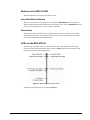
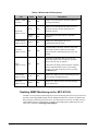
1
Ross Video Limited MFC-8300 Series openGear Controller Cards User Manual 8300DR-004-04 MFC-8300 Series openGear Controller Cards User Manual Ross Part Number: 8300DR-004-04 Release Date: September 28, 2009. Printed in Canada. The information contained in this User Manual is subject to change without notice or obligation. Copyright © 2012 Ross Video Limited. All rights reserved. Contents of this publication may not be reproduced in any form without the written permission of Ross Video Limited. Reproduction or reverse engineering of copyrighted software is prohibited. Patents This product is protected by the following US Patents: 4,205,346; 5,115,314; 5,280,346; 5,561,404; 7,034,886; 7,508,455. This product is protected by the following Canadian Patents: 2039277; 1237518; 1127289. Other patents pending. Notice The material in this manual is furnished for informational use only. It is subject to change without notice and should not be construed as a commitment by Ross Video Limited. Ross Video Limited assumes no responsibility or liability for errors or inaccuracies that may appear in this manual. Trademarks is a registered trademark of Ross Video Limited. is a registered trademark of Ross Video Limited. DashBoard Control System™ is a trademark of Ross Video Limited. Ross, ROSS, ROSS , and MLE are registered trademarks of Ross Video Limited. All other product names and any registered and unregistered trademarks mentioned in this manual are used for identification purposes only and remain the exclusive property of their respective owners. Important Regulatory and Safety Notices Before using this product and any associated equipment, refer to the “Important Safety Instructions” listed below so as to avoid personnel injury and to prevent product damage. Products may require specific equipment, and /or installation procedures be carried out to satisfy certain regulatory compliance requirements. Notices have been included in this publication to call attention to these Specific requirements. Symbol Meanings This symbol on the equipment refers you to important operating and maintenance (servicing) instructions within the Product Manual Documentation. Failure to heed this information may present a major risk of damage or injury to persons or equipment. The symbol with the word “Warning” within the equipment manual indicates a potentially hazardous situation, which if not avoided, could result in death or serious injury. Warning The symbol with the word “Caution” within the equipment manual indicates a potentially hazardous situation, which if not avoided, may result in minor or moderate injury. It may also be used to alert against unsafe practices. Caution The symbol with the word “Notice” within the equipment manual indicates a situation, which if not avoided, may result in major or minor equipment damage or a situation which could place the equipment in a non-compliant operating state. Notice This symbol is used to alert the user that an electrical or electronic device or assembly is susceptible to damage from an ESD event. ESD Susceptibility Important Safety Instructions Caution This product is intended to be a component product of the openGear 8300 series frame. Refer to the openGear 8300 series frame User Manual for important safety instructions regarding the proper installation and safe operation of the frame as well as it’s component products. Warning Certain parts of this equipment namely the power supply area still present a safety hazard, with the power switch in the OFF position. To avoid electrical shock, disconnect all A/C power cords from the chassis' rear appliance connectors before servicing this area. Warning Service barriers within this product are intended to protect the operator and service personnel from hazardous voltages. For continued safety, replace all barriers after any servicing. This product contains safety critical parts, which if incorrectly replaced may present a risk of fire or electrical shock. Components contained within the product’s power supplies and power supply area, are not intended to be customer serviced and should be returned to the factory for repair. To reduce the risk of fire, replacement fuses must be the same type and rating. Only use attachments/accessories specified by the manufacturer. EMC Notices US FCC Part 15 This equipment has been tested and found to comply with the limits for a class A Digital device, pursuant to part 15 of the FCC Rules. These limits are designed to provide reasonable protection against harmful interference when the equipment is operated in a commercial environment. This equipment generates, uses, and can radiate radio frequency energy and, if not installed and used in accordance with the instruction manual, may cause harmful interference to radio communications. Operation of this equipment in a residential area is likely to cause harmful interference in which case users will be required to correct the interference at their own expense. Changes or modifications to this equipment not expressly approved by Ross Video Ltd. could void the user’s authority to operate this equipment. Notice CANADA This Class “A” digital apparatus complies with Canadian ICES-003. Cet appareil numerique de classe “A” est conforme à la norme NMB-003 du Canada. EUROPE This equipment is in compliance with the essential requirements and other relevant provisions of CE Directive 93/68/EEC. INTERNATIONAL This equipment has been tested to CISPR 22:1997 along with amendments A1:2000 and A2:2002 and found to comply with the limits for a Class A Digital device. This is a Class A product. In domestic environments this product may cause radio interference in which case the user may have to take adequate measures. Notice Maintenance/User Serviceable Parts Routine maintenance to this openGear product is not required. This product contains no user serviceable parts. If the module does not appear to be working properly, please contact Technical Support using the numbers listed under the “Contact Us” section on the last page of this manual. All openGear products are covered by a generous 5-year warranty and will be repaired without charge for materials or labor within this period. Refer to the “Warranty and Repair Policy” section in this manual for details. Environmental Information The equipment that you purchased required the extraction and use of natural resources for its production. It may contain hazardous substances that could impact health and the environment. To avoid the potential release of those substances into the environment and to diminish the need for the extraction of natural resources, Ross Video encourages you to use the appropriate take-back systems. These systems will reuse or recycle most of the materials from your end-of-life equipment in an environmentally friendly and health conscious manner. The crossed-out wheeled bin symbol invites you to use these systems. If you need more information on the collection, reuse, and recycling systems, please contact your local or regional waste administration. You can also contact Ross Video for more information on the environmental performances of our products. Contents Introduction 1-1 In This Chapter ....................................................................................................................... 1-1 A Word of Thanks .................................................................................................... 1-1 Features ................................................................................................................................... 1-2 Documentation Terms ............................................................................................................. 1-3 Installation 2-1 In This Chapter ....................................................................................................................... 2-1 Before You Begin ................................................................................................................... 2-2 Static Discharge ........................................................................................................ 2-2 Unpacking................................................................................................................. 2-2 Isntalling an MFC-8300 Controller Card ................................................................................ 2-3 Installing an MFC-8300 Controller Card .................................................................. 2-3 Network Configuration ........................................................................................................... 2-4 Automatic Configuration using DHCP ..................................................................... 2-4 Preset Configuration using DIP Switches ................................................................. 2-5 Custom User Configuration via DashBoard ............................................................. 2-6 Enabling SNMP Support ........................................................................................................ 2-8 Enabling SNMP Support for the MFC-8310-N and MFC-8320-N........................... 2-8 Configuring the SNMP Agent using DashBoard ...................................................... 2-8 Software Upgrades for the MFC-8300 Controller Card ........................................................ 2-10 MFC-8320-S Setup 3-1 In This Chapter ....................................................................................................................... 3-1 Controls for the MFC-8320-S ................................................................................................ 3-2 SW3 DIP Switch Settings on the MFC-8320-S ........................................................ 3-2 Buttons and Jumpers on the MFC-8320-S ................................................................ 3-3 LEDs on the MFC-8320-S ........................................................................................ 3-4 MFC-8320-N Series Setup 4-1 In This Chapter ....................................................................................................................... 4-1 Controls for the MFC-8320-N ................................................................................................ 4-2 SW3 DIP Switch Settings on the MFC-8320-N ....................................................... 4-2 Buttons and Jumpers on the MFC-8320-N ............................................................... 4-3 LEDs on the MFC-8320-N ....................................................................................... 4-4 SNMP Monitoring on the MFC-8320-N .................................................................. 4-5 MFC-8310 Setup 5-1 In This Chapter ....................................................................................................................... 5-1 Controls for the MFC-8310 .................................................................................................... 5-2 Buttons and Jumpers on the MFC-8310 ................................................................... 5-2 LEDs on the MFC-8310 ........................................................................................... 5-3 MFC-8300 Series User Manual (Iss. 04A) Contents i MFC-8310-N Series Setup 6-1 In This Chapter .......................................................................................................................6-1 Controls for the MFC-8310-N ................................................................................................6-2 SW1_DIP Switch Settings on the MFC-8310-N.......................................................6-2 Buttons on the MFC-8310-N ....................................................................................6-3 LEDs on the MFC-8310-N .......................................................................................6-3 Enabling SNMP Monitoring on the MFC-8310-N ..................................................6-4 DataSafe™ 7-1 In This Chapter .......................................................................................................................7-1 Overview .................................................................................................................................7-2 DataSafe and Network Controller Cards .................................................................................7-3 Using the Alarm Button ............................................................................................7-3 Enabling DataSafe ....................................................................................................7-3 Re-naming a Card Slot ..............................................................................................7-3 Hiding the DataSafe Warnings .................................................................................7-4 Forcing DataSafe Files to Load ................................................................................7-4 Resetting a Network Controller Card to Factory Defaults ........................................7-4 DashBoard Menus 8-1 In This Chapter .......................................................................................................................8-1 Status Menus ...........................................................................................................................8-2 Setup Tab ................................................................................................................................8-6 Restoring Menu Items to Factory Default Settings ...................................................8-6 Network Tab ...........................................................................................................................8-8 DataSafe Tab...........................................................................................................................8-9 SNMP Tab ............................................................................................................................8-11 Notes on the Trap/Notification Target Feature .......................................................8-11 Service Information 9-1 In This Chapter .......................................................................................................................9-1 Troubleshooting Checklist ......................................................................................................9-2 Frame Controller Alarm Mute/Bootload Button .......................................................9-2 Warranty and Repair Policy ....................................................................................................9-3 ii Contents MFC-8300 Series User Manual (Iss. 04A) Introduction In This Chapter This chapter contains the following sections: A Word of Thanks Features Documentation Terms A Word of Thanks Congratulations on choosing the openGear openGear MFC-8300 Series Controller Card. Your MFC8300 Series Controller Card is part of a full line of products within the openGear Terminal Equipment family of products, backed by Ross Video’s experience in engineering and design expertise since 1974. You will be pleased at how easily your new SRA-8201A and/or SRA-8601A fit into your overall working environment. Equally pleasing is the products’ quality, reliability and functionality. Thank you for joining the group of worldwide satisfied Ross Video customers! Should you have a question pertaining to the installation or operation of your products, please contact us at the numbers listed on the back cover of this manual. Our technical support staff is always available for consultation, training, or service. MFC-8300 Series User Manual (Iss. 04A) Introduction 1-1 Features The MFC-8300 Series Controller Cards are designed for the openGear DFR-8300 series frames and offer a range of monitoring and control options based on the card model. The following sections outline the features for each available MFC-8300 Series Controller Card offered by Ross Video. Table 1.1 Feature Comparison Chart Features 8320-S 8320-N 8320NS 8310 8310-N 8310NS Monitors frame power usage and sets the fan speed accordingly* Monitors the frame door and PS-8300(s) Monitors the fan door and notifies the user if it is left open too long Monitors the status of other cards in the frame via the internal bus Supports the DataSafe™ feature in DashBoard Generates alarms if any of the monitored functions develop errors Provides an ethernet connection for remote control and monitoring through DashBoard † Stores the IP Address settings on the card Stores the IP Address settings on the frame Provides SNMP Monitoring Supports more than one concurrent TCP Control connections, such as DashBoard, or a control panel Available for the DFR-8310 series frames Available for the DFR-832x series frames 5-year transferable warranty * Higher power consumption requires higher fan speed for adequate cooling. The fans always run at maximum speed for 5 seconds after the fan door is closed, then adjust to the appropriate level based on power consumption. † Only available when the MFC-8320-S is installed in an DFR-832x series frame. 1-2 Introduction MFC-8300 Series User Manual (Iss. 04A) Documentation Terms The following terms are used throughout this guide: • “Frame” refers to any openGear frame within your video system. • All references to the DFR-8300 series frame also includes all versions of the 10-slot and 20-slot frames and any available options unless otherwise noted. • All references to the DFR-832x series frames also includes all versions of the DFR-8320 and DFR-8321 series frames unless otherwise noted. • All references to the MFC-8310-N Network Controller Card also includes the MFC8310-NS unless otherwise noted. • All references to the MFC-8320-N Network Controller Card also includes the MFC8320-NS unless otherwise noted. • References to DIP Switch positions on the card are in the following format: SW#-X where # represents the silk-screen label on the card for the set of DIP Switches, and X represents the position. For example, SW1-8 refers to the SW1 Switch position 8. • “Operator” and “User” refer to the person who uses DashBoard Control System. • “Board”, and “Card” refer to openGear terminal devices within openGear frames, including all components and switches. • “System” and “Video system” refer to the mix of interconnected production and terminal equipment in your environment. • The “Operating Tips” and “Note” boxes are used throughout this manual to provide additional user information. MFC-8300 Series User Manual (Iss. 04A) Introduction 1-3 1-4 Introduction MFC-8300 Series User Manual (Iss. 04A) Installation In This Chapter This chapter provides instructions for installing the MFC-8300 Controller Card, configuring the network settings, and enabling the SNMP monitoring option This following topics are discussed: Before You Begin Installing an MFC-8300 Controller Card Network Configuration Enabling SNMP Support Software Upgrades for the MFC-8300 Controller Card MFC-8300 Series User Manual (Iss. 04A) Installation 2-1 Before You Begin Before you begin, ensure to read the following sections. Static Discharge Throughout this chapter, please heed the following cautionary note: Static discharge can cause serious damage to sensitive semiconductor devices. Avoid handling circuit boards in high static environments such as carpeted areas, and when wearing synthetic fiber clothing. Always exercise proper grounding precautions when working on circuit boards and related equipment. ESD Susceptibility Unpacking Unpack each card you received from the shipping container, and check the contents. If any items are missing or damaged, contact your openGear sales representative or Ross Video directly. 2-2 Installation MFC-8300 Series User Manual (Iss. 04A) Isntalling an MFC-8300 Controller Card This section outlines how to install an MFC-8300 Controller Card in a DFR-8300 series frame. The same procedure applies regardless of the frame or card type. Installing an MFC-8300 Controller Card Use the following procedure to install an MFC-8300 Controller Card into a DFR-8300 series frame: 1. With the frame door open, unscrew the MFC-8300 Card Retaining Screw (Part No. 850040) enough to eliminate any protrusion into the card guide slot on the right of the screw. If necessary, remove any cards from the frame that would interfere with easy access and lines of sight. Refer to the documentation that came with your frame for details on opening the frame door. 2. Insert the MFC-8300 Controller Card, with the component side out (Figure 2.1 ) into the card guides between the dividing wall and the last slot, ensuring the card does not touch the Card Retaining Screw. Figure 2.1 MFC-8300 Controller Card and Unscrewed Retaining Screw (MFC-8310 shown) 3. Slide the card in the slot until firmly seated and such that the Card Retaining Screw hole on the bottom front edge aligns with the mounted nut beside the bottom guide slot. 4. Tighten the Card Retaining Screw through MFC-8300 Card Retaining Screw hole, to ensure the card does not move from the slot. 5. Power up the frame. Refer to the documentation that came with your frame for details. 6. Ensure the frame door is closed. 7. Check the operation of the fans. If the fans do not operate, verify that: • the MFC-8300 Controller Card is seated properly in the frame backplane. • the MFC-8300 Controller Card is aligned to the Fan PCB when the door is closed. This completes the installation of an MFC-8300 Controller Card in a DFR-8300 series frame. MFC-8300 Series User Manual (Iss. 04A) Installation 2-3 Network Configuration The MFC-8310-N series, the MFC-8320-S, and the MFC-8320-N Network Controller cards feature an ethernet interface which allows cards in the DFR-8300 series frame to be monitored and controlled using the DashBoard Control System. Network connection with an MFC-8320-S is only available in a DFR-832x series frame. Communication is possible only when the Network Controller card is suitably configured to match the network to which it is connected. Note — Consult your IT Department before configuring any network settings. This section explains the necessary parameters and lists several possible methods for managing these parameters. • Automatic configuration using DHCP — When shipped from the factory, the Network Controller card is configured to automatically obtain network settings from a Dynamic Host Configuration Protocol (DHCP) server. Since most networks have a DHCP server available, this method is applicable to most users and is the recommended method. • Preset configuration using DIP switch(es) — The Network Controller card can be forced to use specific pre-defined network settings by means of DIP switches located on the card surface. This can be used to establish initial communications when no DHCP server is available, or to override a custom user configuration. • Custom user configuration via DashBoard — Using the network setting options available in the DashBoard Control System, you may configure the Network Controller card to use a static address or enable DHCP for automatic configuration. This can only be done once communication has been established. Notice — Before proceeding, ensure that the DashBoard Control System software is installed on your computer. Automatic Configuration using DHCP This method assumes that the Network Controller card is using the factory default values for the network settings. Note — The Network Controller card boots much faster than a typical DHCP server. In the case of a facility-wide power failure, the Network Controller card may not appear on the network if communications with the DHCP server cannot be established. Once the DHCP server becomes operational, re-boot the Network Controller card to re-establish communications. To avoid this, you may use a static configuration as described in the section “Custom User Configuration via DashBoard”. Use the following procedure to establish communications with the Network Controller card: 1. Ensure that DFR-8300 series frame is connected to the same network as your DashBoard computer. 2. Launch the DashBoard application on your computer. 3. Power on the DFR-8300 series frame that the Network Controller card is installed in. 2-4 Installation MFC-8300 Series User Manual (Iss. 04A) 4. Wait approximately 30 seconds while the frame establishes network communications. 5. Verify that the Network Controller card displays in the Tree View of DashBoard. 6. Should the card fail to display after two minutes: • Verify the ethernet cables are properly connected. • Check the link/activity LEDs found on the ethernet RJ-45 connectors. • Ensure the network settings for the Network Controller card are set to the factory default values. • If all cables are connected and the LEDs do not indicate an error, then automatic configuration is not possible. Proceed to the section “Preset Configuration using DIP Switches”. This completes the procedure for establishing communications with the Network Controller card. Preset Configuration using DIP Switches This method is used to established initial communications when no DHCP server is available, or to override a custom user configuration and is intended to be used temporarily in order to establish communication. Once initial communications are established, the Network Controller card should be configured for either DHCP or Static operation. Note — Use of this method for normal operation is not recommended, as there is a high chance of IP Address conflicts. Use the following procedure to use a preset network configuration using the DIP Switch(es): 1. Power down the DFR-8300 series frame that houses the Network Controller card. 2. Quit DashBoard on your computer. 3. Set the DIP Switch to chose the preset IP Address. 4. • If you are using an MFC-8320-S in a DFR-832x series frame, refer to the section “SW3 DIP Switch Settings on the MFC-8320-S”. • If you are using an MFC-8320-N, refer to the section “SW3 DIP Switch Settings on the MFC-8320-N”. • If you are using an MFC-8310-N, refer to the section “SW1_DIP Switch Settings on the MFC-8310-N”. Ensure the network settings of your computer are compatible with those chosen for the Network Controller card. Note — The IP Addresses of the Network Controller card and your computer must be similar, but not identical, and the Subnet Mask must match exactly the same. For example, if the Network Controller card has an IP Address of 192.168.1.1, then your computer should be configured for an IP Address with 192.168.1.X where X is a number other than 1. MFC-8300 Series User Manual (Iss. 04A) Installation 2-5 5. To prevent IP Address conflicts, isolate the Network Controller card and your DashBoard computer from the rest of your network. • If you are using a hub or switch, unplug all devices except the Network Controller card and your DashBoard computer; or • Connect the DFR-8300 series frame directly to the DashBoard computer. Note — The MFC-8310-N does not support Auto-MDIX, so a crossover cable may be needed for direct connection. The MFC-8320-S and MFC-8320-N support Auto-MDIX, enabling you to use any ethernet cable when connecting the frame to the DashBoard computer. 6. Launch DashBoard on your computer. 7. Power up the DFR-8300 series frame. 8. Wait approximately 30 seconds while the frame establishes network communications. 9. Verify that the Network Controller card displays in the Tree View of DashBoard. 10. Should the card fail to display after a minute or two: • Verify the ethernet cables are properly connected. • Check the link/activity LEDs found on the ethernet RJ-45 connectors. • Verify that you have properly performed each step of this procedure. • Contact Ross Video Technical Support if you cannot establish a connection. This completes the procedure for using a preset network configuration using the DIP Switch(es). Custom User Configuration via DashBoard Once communication has been establish with the Network Controller card, the network settings may be further adjusted using the following procedure. Note that the steps are optional, you may perform as many, or as few, as needed. Use the following procedure to configure the network settings via DashBoard: 1. In DashBoard, display the Device tab of the Network Controller card by double-clicking its status indicator in the Basic Tree View. 2. From the Device tab, select the Network tab. 3. To change the display name of the frame, enter a new name in the Frame Name field. 4. To change the Network Time Server address, enter the new IP Address in the NTP Server field. 5. To change between Static and DHCP addressing, select an option in the Addressing Mode area. 2-6 Installation MFC-8300 Series User Manual (Iss. 04A) 6. Configure the network settings as required: • IP Address — This is the IP Address of the Network Controller card. • Subnet Mask — This is the subnet mask address for your LAN. • Default Gateway — This is the IP Address for connection outside the subnet. 7. To save the new settings, click Apply in the Network tab. The settings are saved immediately and take effect except when overridden by DIP Switch settings.Click Cancel to revert to the previous settings. This completes the procedure for configuring the network settings via DashBoard. MFC-8300 Series User Manual (Iss. 04A) Installation 2-7 Enabling SNMP Support Certain versions of the MFC-8300 Controller Cards provide support for remote monitoring and control of your frame and openGear cards using SNMP (Simple Network Management Protocol), which is compatible with many third-party monitoring and control tools. Refer to Table 1.1 for a list of cards that support SNMP Note — The MFC-8320-S does not support SNMP. Enabling SNMP Support for the MFC-8310-N and MFC-8320-N Before proceeding with this section, ensure that you have configured the network settings for your card as outlined in the section “Network Configuration”. Note — If SNMP is enabled on an MFC-8310-N, it will perform as an MFC-8310NS although DashBoard and SNMP still displays MFC-8310-N. This also applies to the MFC-8320-NS, but DashBoard displays MFC-8320-N. Use the following procedure to enable SNMP support using the SNMP tab in DashBoard: 1. In DashBoard, display the Device tab of the MFC-8310-N, or MFC-8320-N, by doubleclicking its status indicator in the Basic Tree View. 2. From the Device tab, select the Setup tab. 3. In the Licensable Features area, make a note of the information displayed in the SNMP Request Code field. 4. Contact Ross Video Technical Support. • When you speak to the Technical Support representative, tell them your name, your facility name, and the SNMP Request Code displayed in the Setup tab. • You will be given a License Key that must be entered in the SNMP Feature Key field of the Setup tab. 5. Enter the License Key in the SNMP Feature Key field. 6. When the installation is complete, verify that the Setup tab displays “Licensed” in the SNMP Feature field and that the SNMP tab is now available in the Device View. This completes the procedure for enabling SNMP support using the SNMP tab in DashBoard. Configuring the SNMP Agent using DashBoard The SNMP agent on the frame will accept SNMP GET and SET requests on the default SNMP port (161), using SNMP version 1 or SNMP version 2c. The SNMP Agent will send SNMP traps to one or more notification targets, with user-configurable address, port, and protocol version number. 2-8 Installation MFC-8300 Series User Manual (Iss. 04A) Use the following procedure to configure your SNMP Agent via DashBoard: 1. In DashBoard, display the Device tab of the card by double-clicking its status indicator in the Basic Tree View. 2. From the Device tab, select the SNMP tab. 3. Set the required parameters as follows: • Read Community String — Enter the SNMP password for GET requests. For example, public. • Write Community String — Enter the SNMP password for SET requests. For example, private. 4. To add a trap/notification target, edit the Trap/Notification Target field using the format of ##.#.#.##/xxx;yy;zz. • ##.#.#.## — Represents the Target IP address to which traps should be sent. • xxx — Represents the UDP Port number to which traps should be sent. • yy— Represents the SNMP protocol version to be used for traps to this target. • zz — Represents the Target community string. An example is provided in the SNMP tab in DashBoard. 5. Click Add to add the new target to the list. 6. Click Apply to apply your changes or Cancel to discard the changes. To remove a trap/notification target, select the target in the list, and click Delete. This completes the procedure to configure your SNMP Agent via DashBoard. MFC-8300 Series User Manual (Iss. 04A) Installation 2-9 Software Upgrades for the MFC-8300 Controller Card The MFC-8300 Controller Card can be upgraded in the field from DashBoard (via TCP/IP). Note — Contact Ross Technical Support if you are upgrading from a software version of v1.11 or lower. You must upgrade to v1.12 before upgrading to a version higher than v1.12. Use the following procedure to upgrade the software on a MFC-8300 Controller Card: 1. Contact Ross Technical Support for the latest software version file. 2. In DashBoard, display the Device tab of the MFC-8300 Controller Card by doubleclicking its status indicator in the Basic Tree View. 3. From the Device tab, click Upload to display the Select file for upload dialog. 4. Navigate to the *.bin upload file you wish to upload for the MFC-8300 Controller Card. 5. Click Open to display a confirmation dialog. 6. Click Continue in the Confirm Upload dialog to return to the Device tab. 7. Follow the on-screen instructions to upload the selected file to the card. 8. Wait until the upgrade is performed. An Upload Complete dialog displays once the upgrade is performed. 9. Press OK in the Upload Complete dialog. 10. Click the Reboot button in the Device tab for the upgraded card. DashBoard automatically saves all your settings before starting the reboot process. Operating Tip — The Reboot button is disabled during the upload process. Once the upload process completes, the Reboot button is enabled. 11. Press OK in the Confirm dialog. 12. Press Yes to begin the reboot process. 13. Monitor the upgrade progress bar displayed in DashBoard while the software is upgraded on your MFC-8300 Controller Card. Note — The communications processor of the MFC-8300 Controller Card requires approximately 30 seconds to re-start and re-establish network communications. 14. The reboot process is complete once: 2-10 Installation • the cards are no longer grayed out • the status indicators for the Card State and Connection return to their previous status. MFC-8300 Series User Manual (Iss. 04A) This completes the procedure to upgrade the software on a MFC-8300 Controller Card. MFC-8300 Series User Manual (Iss. 04A) Installation 2-11 MFC-8320-S Setup In This Chapter This chapter provides information on setting up and using the MFC-8320-S Controller Card This following topics are discussed: Controls for the MFC-8320-S MFC-8300 Series User Manual (Iss. 04A) MFC-8320-S Setup 3-1 Controls for the MFC-8320-S This section provides information on the jumpers, buttons and LEDs for the MFC-8320-S. Refer to Figure 3.1 for the location of card control features such as the Alarm Mute button, and the Alarm Config jumpers. Note — The functionality of the MFC-8320-S depends on the openGear frame it is installed in.When installed in a DFR-8310 series frame, the MFC-8320-S does not provide an ethernet connection. However, when installed in a DFR-832x series frame, the MFC-8320-S provides a single DashBoard connection. Figure 3.1 MFC-8320-S Card Controls SW3 DIP Switch Settings on the MFC-8320-S This section briefly summarizes the SW3 DIP Switch settings on the MFC-8320-S. Refer to MFC-8320-S for the location of SW3. Note Figure 3.2 shows the DIP Switches in the ON position. Figure 3.2 SW3 DIP Switch — Set to the ON Positions SW3-1, SW3-2 — IP Address Setup SW3-1 and SW3-2 are used in conjunction with the DashBoard menus to set the IP Address of the MFC-8320-S. Refer to Table 3.1 for DIP Switch positions. For more information on configuring the network settings for your card, refer to the section “Network Configuration”. Notice — The settings related to ethernet setup only apply when using a DFR832x frame. When installed in a DFR-8310 series frame, the ethernet port is not supported by the MFC-8320-S, and no communication with DashBoard is possible. 3-2 MFC-8320-S Setup MFC-8300 Series User Manual (Iss. 04A) Table 3.1 SW3-1 and SW3-2 Positions SW3-1 Position SW3-2 Position Descriptions OFF OFF The card IP Address can be set by the user from the DashBoard Network tab. This is the default setting. OFF ON The card IP Address is automatically assigned (DHCP Mode). ON OFF The card IP Address is set to 192.168.2.1 The card Subnet Mask is set to 255.255.0.0. ON ON The card IP Address is set to 10.1.2.1. The card Subnet Mask is set to 255.255.0.0. SW3-3, SW3-4 SW3-3 and SW3-4 are not implemented at this time. Buttons and Jumpers on the MFC-8320-S This section briefly outlines the various buttons and jumpers located on the MFC-8320-S. Alarm Mute Button (SW1) The Alarm Mute button (SW1) on the card-edge of the MFC-8320-S mutes the audio alarm for two minutes. If a fault condition is still present when the mute timeout ends, the card re-activates the audio alarm. This button is also used as a Bootload button for factory service in the unlikely event of a complete card failure. Reset Button (SW2) The Reset button (SW2) is not implemented at this time. Alarm Config Jumper (J4) The Alarm Config jumper (J4) enables or disables the audio alarm signal. The Alarm LED is still lit if alarm conditions are occurring, but the audio will be off. Refer to Figure 3.3 and the card labeling for jumper positions. Figure 3.3 Alarm Config Jumper — Pin Positions • Enabled — To enable the alarm feature, set the jumper into Position 1+2. • Disabled — To disable the alarm feature, set the jumper into Position 2+3. MFC-8300 Series User Manual (Iss. 04A) MFC-8320-S Setup 3-3 LEDs on the MFC-8320-S The front card-edge of the MFC-8320-S, and the frame door, have LED indicators for the cooling module fan, alarm, and communication activity. Refer to Figure 3.4 for the location of the cardedge LEDs on the MFC-8320-S. Figure 3.4 MFC-8320-S Card-edge Controls Table 3.2 provides information on the LED displays of the MFC-8320-S. Table 3.2 MFC-8320-S LED Descriptions LED Color Description Alarm ( MFC8320-S) Red When lit, this LED indicates an alarm condition is occurring in the frame. OK ( MFC8320-S) Green When lit, this LED indicates the MFC-8320-S is operating normally. CAN ( MFC8320-S) Yellow When flashing, this LED indicates the MFC-8320-S is communicating with the other cards within the frame. When off, this LED indicates an absence of incoming messages. When lit, this LED indicates a valid ethernet connection but is not receiving messages from DashBoard, a control panel, or an external SNMP agent. Ethernet ( MFC8320-S) Yellow When flashing, this LED indicates the card is communicating over the ethernet connection to DashBoard, a control panel, or an external SNMP agent. When off, this LED indicates an absence of ethernet connection. 3-4 MFC-8320-S Setup MFC-8300 Series User Manual (Iss. 04A) MFC-8320-N Series Setup In This Chapter This chapter provides information on setting up and using the MFC-8320-N and MFC-8320-NS Controller Cards. The MFC-8320-N and MFC-8320-NS bring ethernet connectivity to the DFR-8300 series frames infrastructure, providing a DashBoard interface to monitor openGear cards in the frame. The MFC-8320-NS includes the SNMP Monitoring option. The following topics are discussed: Controls for the MFC-8320-N MFC-8300 Series User Manual (Iss. 04A) MFC-8320-N Setup 4-1 Controls for the MFC-8320-N This section provides information on the jumpers, buttons and LEDs for the MFC-8320-N and MFC-8320-NS. Refer to Figure 4.1 for the location of card control features such as the Alarm Mute button, and the Alarm Config jumpers. Figure 4.1 MFC-8320-N Card Controls SW3 DIP Switch Settings on the MFC-8320-N This section briefly summarizes the SW3 DIP Switch settings on the MFC-8320-N. Refer to Figure 4.1 for the location of SW3. Note that Figure 4.2 shows the DIP Switches in the ON position. Figure 4.2 SW3 DIP Switch — Set to the ON Positions SW3-1, SW3-2 — IP Address Setup SW3-1 and SW3-2 are used in conjunction with the DashBoard menus to set the IP Address of the MFC-8320-N. Refer to Table 4.1 for DIP Switch positions. For more information on configuring the network settings for your card, refer to the section “Network Configuration. Table 4.1 SW3-1 and SW3-2 Positions SW3-1 Position SW3-2 Position Descriptions OFF OFF The card IP Address can be set by the user from the DashBoard Network tab. This is the default setting. OFF ON The card IP Address is automatically assigned (DHCP Mode). ON OFF The card IP Address is set to 192.168.2.1 The card Subnet Mask is set to 255.255.0.0. 4-2 MFC-8320-N Setup MFC-8300 Series User Manual (Iss. 04A) SW3-1 Position ON SW3-2 Position Descriptions The card IP Address is set to 10.1.2.1. The card Subnet Mask is set to 255.255.0.0. ON SW3-3, SW3-4 SW3-3 and SW3-4 are not implemented at this time. Buttons and Jumpers on the MFC-8320-N This section briefly outlines the various buttons and jumpers located on the MFC-8320-N. the card monitors and reports frame power consumption. Alarm Mute Button (SW1) The Alarm Mute button (SW1) on the card-edge of the MFC-8320-N mutes the audio alarm for two minutes. If a fault condition is still present when the mute timeout ends, the card re-activates the audio alarm. This button is also used as a Bootload button for factory service in the unlikely event of a complete card failure. Reset Button (SW2) The Reset button (SW2) is not implemented at this time. Alarm Config Jumper (J4) The Alarm Config jumper (J4) enables or disables the audio alarm signal. The Alarm LED is still lit if alarm conditions are occurring, but the audio will be off. Refer to Figure 4.3 and the card labeling for jumper positions. Figure 4.3 Alarm Config Jumper — Pin Positions • Enabled — To enable the alarm feature, set the jumper into Position 1+2. • Disabled — To disable the alarm feature, set the jumper into Position 2+3. MFC-8300 Series User Manual (Iss. 04A) MFC-8320-N Setup 4-3 LEDs on the MFC-8320-N The front card-edge of the MFC-8320-N, and the frame door, have LED indicators for the cooling module fan, alarm, and communication activity. (Figure 4.4 ) Figure 4.4 MFC-8320-N Card-edge Controls Table 4.2 provides information on the LED displays of the MFC-8320-N. Table 4.2 MFC-8320-N LED Descriptions LED Alarm ( MFC8320-N) OK ( MFC8320-N) CAN ( MFC8320-N) Ethernet ( MFC8320-N) 4-4 MFC-8320-N Setup Color Description Red When lit, this LED indicates an alarm condition is occurring in the frame. Green When lit, this LED indicates the MFC-8320-N is operating normally. Flashing Green When flashing, this LED indicates a DataSafe mismatch. Flashing Yellow When flashing, this LED indicates the MFC-8320-N is communicating with the other cards within the frame. Off When off, this LED indicates an absence of incoming messages. Yellow When lit, this LED indicates a valid ethernet connection but is not receiving messages from DashBoard, a control panel, or an external SNMP agent. Flashing Yellow When flashing, this LED indicates the card is communicating over the ethernet connection to DashBoard, a control panel, or an external SNMP agent. Off When off, this LED indicates an absence of ethernet connection. MFC-8300 Series User Manual (Iss. 04A) SNMP Monitoring on the MFC-8320-N The MFC-8320-N provides optional support for remote monitoring and control of your frame and openGear cards using SNMP (Simple Network Management Protocol), which is compatible with many third-party monitoring and control tools. You must obtain a license key from Ross Video to enable SNMP support. For information on enabling and configuring the SNMP Agent for your card, refer to the section “Enabling SNMP Support”. MFC-8300 Series User Manual (Iss. 04A) MFC-8320-N Setup 4-5 4-6 MFC-8320-N Setup MFC-8300 Series User Manual (Iss. 04A) MFC-8310 Setup In This Chapter This chapter provides information on using the MFC-8310 Controller Card. The MFC-8310 enables you to monitor the fans, power supply status, and the cards installed in the DFR-8300 series frames. The following topics are discussed: Controls for the MFC-8310 MFC-8300 Series User Manual (Iss. 04A) MFC-8310 Setup 5-1 Controls for the MFC-8310 This section provides information on the jumpers, buttons and LEDs for the MFC-8310. Refer to Figure 5.1 for the location of the LEDs and controls for fan, alarm, and communications. Figure 5.1 MFC-8310 Card-edge Controls Buttons and Jumpers on the MFC-8310 This section briefly summarizes the available buttons and jumpers on the MFC-8310. Refer to Figure 5.1 for button and jumper locations. Alarm Mute/Bootload Button There is an Alarm Mute button on the right side of the DFR-8300 series frames door front. If a card is reporting an error, pressing the Alarm Mute button mutes the audio alarm until another fault condition occurs. This button is also used as a Bootload button for factory service in the unlikely event of a complete card failure. Alarm Configuration Jumper The Alarm Configuration Jumper enables or disables the audio alarm signal. The Alarm LED is still lit if alarm conditions are occurring, but the audio will be off. 5-2 MFC-8310 Setup MFC-8300 Series User Manual (Iss. 04A) LEDs on the MFC-8310 The front-edge of the MFC-8310, and the frame door, have LED indicators for the cooling module fan, alarm, and communication activity. In the DFR-8310 series frames, the CFM-8310 (Cooling Fan Module) provides LED and Alarm switching controls to the front-edge of the DFR-8310 frame door. LED displays and descriptions are provided in Table 5.1. Table 5.1 MFC-8310 LED Descriptions LED Color Description Alarm ( MFC-8310) Red When lit, this LED indicates an alarm condition is occurring in the frame. Status OK (MFC-8310) Green When lit, this LED indicates the MFC-8310 is operating correctly. Comm Activity (MFC-8310) Yellow When lit, this LED indicates the card is communicating within the frame. MFC-8300 Series User Manual (Iss. 04A) MFC-8310 Setup 5-3 5-4 MFC-8310 Setup MFC-8300 Series User Manual (Iss. 04A) MFC-8310-N Series Setup In This Chapter This chapter provides instructions for setting up the MFC-8310-N and MFC-8310-NS Network Controller Cards. The MFC-8310-N brings ethernet connectivity to the DFR-8300 series frame infrastructure, providing a DashBoard interface to monitor openGear cards in the frame. The MFC8310-NS includes the SNMP Monitoring option. . The following topics are discussed: Controls for the MFC-8310-N MFC-8300 Series User Manual (Iss. 04A) MFC-8310-N Setup 6-1 Controls for the MFC-8310-N This section provides information on the jumpers, buttons and LEDs for the MFC-8310-N. Refer to Figure 6.1 for the location of the controls for fan, alarm, and communications. Figure 6.1 MFC-8310-N DIP Switches and Card-edge Buttons SW1_DIP Switch Settings on the MFC-8310-N This section briefly summarizes the available card-edge controls on the MFC-8310-N. Refer to Figure 6.1 and Figure 6.2 for the location of SW1_DIP. Note — You must remove the MFC-8310-N from the frame, or remove the adjacent cards, to access the SW1_DIP Switches. SW1-1 SW1-1 configures the Audio Alarm Disable feature as follows: • ON — This setting activates the feature. Alarms will not be audible. • OFF — This setting de-activates the feature. Alarms will be audible. SW1-2 to SW1-7 SW1-2 to SW1-7 are not implemented at this time. You must leave them in the factory default positions. SW1-8 SW1-8 enables you to select the IP Address of the MFC-8310-N as follows: 6-2 MFC-8310-N Setup ON — This setting enables the card to use the default IP Address of 192.168.1.1 and the Subnet Mask is set to 255.255.0.0. The Default Gateway and NTP Server addresses use the default values. OFF — This setting enables the card to use the IP Address and other network settings as configured by the user. Refer to the section “Network Configuration” on page 2-4 for details. This is the default setting. MFC-8300 Series User Manual (Iss. 04A) Buttons on the MFC-8310-N The following buttons are located on the MFC-8310-N. Alarm Mute/Bootload Button When a card in the frame is reporting an error, pressing the Alarm Mute button will mute the audio alarm until another fault condition occurs. This button is also used as a Bootload button for factory service in the unlikely event of a complete card failure. Reset Button This button is used to restart both of the on-board processors: the fan control processor and the communications processor. The communications processor requires approximately 30 seconds to restart and re-establish network communications. LEDs on the MFC-8310-N The front-edge of the MFC-8310-N, and the frame door, have LED indicators for the cooling module fan, alarm, and communication activity. Refer to Figure 6.2 for the LED indicators and controls for fan, alarm, and communications. Figure 6.2 MFC-8310-N Card-edge Controls LED displays and descriptions are provided in Table 6.1. MFC-8300 Series User Manual (Iss. 04A) MFC-8310-N Setup 6-3 Table 6.1 MFC-8310-N LED Descriptions LED Color Alarm (MFC8310-N) Label Red DS1 When lit, this LED indicates an alarm condition is occurring in the frame. Green DS2 When lit, this LED indicates the MFC-8310-N is operating correctly. The fan control process is operating correctly. Flashing Green DS2 When flashing, this LED indicates a DataSafe mismatch. Yellow DS3 When lit, this LED indicates the card is communicating with the frame. DS4 This LED flashes red briefly when the card is first powered up. If lit at any other time, this LED indicates that the communications processor is not running. Status OK (MFC-8310-N) Comm Activity (MFC-8310-N) Processor (MFC-8310-N) Description Red This LED is lit when the MFC-8310-N is first powered up and the card is booting up. The LED turns off once boot up is complete. Error (MFC-8310-N) Red DS5 Transmitting (MFC-8310-N) Green DS6 When lit, the MFC-8310-N is transmitting messages on the internal communications bus. Receiving (MFC-8310-N) Yellow DS7 When lit, the MFC-8310-N is receiving messages via the internal bus. If this LED is lit during normal operation, it indicates that the communications software is not running correctly. You must restart the process by pressing the Reset button. Enabling SNMP Monitoring on the MFC-8310-N The MFC-8310-N provides optional support for remote monitoring and control of your frame and openGear cards using SNMP (Simple Network Management Protocol), which is compatible with many third-party monitoring and control tools. You must obtain a license key from Ross Video to enable SNMP support. For information on enabling and configuring the SNMP Agent for your card, refer to the section “Enabling SNMP Support”. 6-4 MFC-8310-N Setup MFC-8300 Series User Manual (Iss. 04A) DataSafe™ In This Chapter DataSafe ™ enables you to load and store card parameters automatically, or you can load and store the parameters to and from a single file in DashBoard. This feature is available for frames using the MFC8310-N and MFC-8320-N cards only. For more information on using the DataSafe feature in DashBoard, refer to your DashBoard Control System User Manual. Note — DashBoard version 2.3.0 or higher is required to access DataSafe features. The following topics are discussed: Overview DataSafe and Network Controller Cards MFC-8300 Series User Manual (Iss. 04A) DataSafe™ 7-1 Overview The following DataSafe features are available for your Network Controller card: • The Network Controller card monitors all traffic going through it. On power-up, the Network Controller card queries for all card information. • Changes to writable parameters of cards is noted and the current version of all parameters is stored. Parameter data is stored locally on the network card for every slot independently. • Parameter data can be saved in a single file. • DataSafe enables the user to send all the parameter data to a card slot or to every slot on the network that matches. • You can use a limited DashBoard view to update a subset of cards instead of the entire connected view. DashBoard sends the file to a specific network card and slot for use. Once received, it updates the card if the attached card matches the data sent. • DataSafe stores and recalls the parameters automatically with or without a network connection. • When a DataSafe mismatch occurs, there is an audible alarm from the card and a warning message is displayed in DashBoard. You can clear the alarm using an option in the Setup tab, or by using the card-edge controls. A DataSafe mismatch occurs when the software version or the card type does not match the saved data for that slot. • Note that DataSafe is disabled by default. For More Information… 7-2 DataSafe™ • on the options available in the DataSafe tab, refer to the section “DataSafe Tab”. • on enabling DataSafe for your Network Controller card, refer to the section “Enabling DataSafe”. MFC-8300 Series User Manual (Iss. 04A) DataSafe and Network Controller Cards This section briefly summarizes the DataSafe™ options available for the Network Controller Cards. For more information on using DataSafe in DashBoard, refer to the DashBoard Control System User Manual. Using the Alarm Button An audible alarm indicates when a DataSafe mismatch occurs, such as when a card is installed that does not match the compatibility range of the DataSafe saved data. • Single pressing the Alarm button mutes the audible alarm, but does not mask the alarm displayed in DashBoard. For information on masking DataSafe mismatch warnings, refer to the section “Hiding the DataSafe Warnings”. • Holding the Alarm button down for approximately 5 seconds causes the new settings of all cards to be copied to the saved DataSafe slots. Enabling DataSafe All slot fields in the DataSafe tab of your Network Controller Card are set to Disable by default. The Disable feature prevents DashBoard from automatically recalling the card parameters for the specified slot. You may still monitor the status of the cards in those slots, and DashBoard still updates the slot information when a new card is installed or when a card is removed from the slot and replaced with another card. Use the following procedure to enable DataSafe for a specific slot: 1. From the Tree View in DashBoard, double-click the Network Controller Card to display a corresponding Device Tab in the Device View. 2. Select the DataSafe tab. 3. Locate the card slot(s) you wish to enable DataSafe for. 4. De-select the corresponding checkbox in the Disable column. This completes the procedure for enabling DataSafe for a specific slot. Re-naming a Card Slot DashBoard enables you to re-name a card slot and have that name display in all Tree Views and the DataSafe tab window for the specific Network Controller Card. Use the following procedure to re-name an openGear slot in the Tree View: 1. From the Tree View in DashBoard, double-click the Network Controller Card to display a corresponding Device Tab in the Device View. 2. Select the Setup tab. MFC-8300 Series User Manual (Iss. 04A) DataSafe™ 7-3 3. In the Card Slot Names section of the Setup tab, locate the slot you wish to re-name. 4. Enter the new name for the card slot in the text field provided. This completes the procedure for re-naming an openGear slot in the Tree View . Hiding the DataSafe Warnings A DataSafe mismatch warning occurs in DashBoard when one of the following has occurred: • a card of the same type is installed that does not match the software of the card previously installed in that slot • a card of a different type is installed in the slot DashBoard includes a Mask Warning option in the DataSafe tab for each Network Controller Card. Enabling the Mask Warning option prevents error messages from displaying in the Data Safe State field of the Hardware tab. Use the following procedure to hide DataSafe mismatch warnings in DashBoard: 1. From the Tree View in DashBoard, double-click the Network Controller Card to display a corresponding Device Tab in the Device View. 2. Select the DataSafe tab. 3. Mask the DataSafe mismatch warnings as follows: • Checkbox unselected — DashBoard displays an error message in the Data Safe State field of the Hardware tab. Information is also displayed in the Conflict field of the DataSafe tab to alert the user that a software mismatch is occurring. This is the default setting. • Checkbox selected — This feature is disabled. DashBoard does not update the Data Safe State field of the Hardware tab, nor the Conflict field of the DataSafe tab. This completes the procedure for hiding DataSafe mismatch warnings in DashBoard. Forcing DataSafe Files to Load The Conflict field in the DataSafe tab indicates when a currently installed card has a card type or software incompatibility. • When there is a DataSafe mismatch on the slot, the Update Slot button is enabled for that slot. Click this button to replace the last saved parameters with the current card parameters. • Use the Force button in the DataSafe tab to force the currently saved DataSafe data to load to all cards with software mismatches and store the new information. Refer to the DashBoard Control System User Manual for details. Resetting a Network Controller Card to Factory Defaults Through DashBoard, you can reset the factory settings of the Network Controller Card using the Restore button in the Setup tab. Note that the frame name is unaffected. 7-4 DataSafe™ MFC-8300 Series User Manual (Iss. 04A) Important — Pressing the Restore button erases all DataSafe data for the Network Controller Card. Pressing the Restore button in the Setup tab of the Network Controller card performs the following tasks in DashBoard: • All values in the Setup tab of the Network Controller card are reset to the factory defaults. • All Slot names are deleted. Slot name fields are blank and all DashBoard fields are updated with the default names. MFC-8300 Series User Manual (Iss. 04A) DataSafe™ 7-5 7-6 DataSafe™ MFC-8300 Series User Manual (Iss. 04A) DashBoard Menus In This Chapter This chapter provides information the DashBoard menus available for the MFC-8300 Series Controller Cards. Note that some of the available menus and options are dependent on the card you are using. Default values are indicated with an asterisk (*). The DashBoard Control System enables you to monitor and control openGear frames and cards from a computer. DashBoard communicates with other cards in the DFR-8300 series frame through the MFC8300 Series Controller Cards. You can download the DashBoard software and manual from the Ross Video website. The following topics are discussed: Status Tab Setup Tab Network Tab DataSafe Tab SNMP Tab MFC-8300 Series User Manual (Iss. 04A) DashBoard Menus 8-1 Status Menus Table 8.1 summarizes the Status tab parameters available in DashBoard for the MFC-8300 Series Controller Cards. The Status tabs provide read-only information such as software revision issue, fan door status, and power consumption. Table 8.1 Status Tab Items Tab Title Item Parameters Name as defined by the user in the Network tab. Refer to Table 8.4. Frame Name Indicates the Frame Serial Number. This is not applicable to the MFC-8310-N. Frame S/N Product (Readonly) Product MFC-8310-N , or MFC-8320-N, or MFC-8320-S Supplier Ross Video Ltd. Board Rev ## Indicates the hardware revision Board S/N ######-### Indicates the card serial number MAC Address ##-##-##-##-##-## MAC Address for the card Software Rev #.## Indicates the card software version DHCP - set by user Static - set by user Network (Read-only) Description SW3-1 and SW3-2 are set to OFF; the Addressing Mode is set to DHCP in DashBoard. The network automatically assigns the card ethernet settings. SW3-1 and SW3-2 are set to OFF; the Addressing Mode is set to Static in DashBoard. User defines the ethernet settings from the Network tab. Network Source DHCP - set by DIP SW3-1 is set to OFF and SW3-2 is set to ON. The network automatically assigns the card ethernet settings. This is not applicable to the MFC-8320-S. Factory Default 1 8-2 DashBoard Menus SW3-1 is set to ON and SW3-2 is set to OFF. The IP Address of the card is set to 192.168.2.1. This is not applicable to the MFC-8320-S. MFC-8300 Series User Manual (Iss. 04A) Tab Title Network (Read-only) Item Parameters Description Factory Default 2 SW3-1 and SW3-2 are set to ON. The IP Address of the card is set to 10.1.2.1. This is not applicable to the MFC-8320-S. IP Address ##.#.###.### IP Address of the card Subnet Mask ###.###.#.# Subnet Mask for the card Default Gateway ##.#.#.# The card gateway NTP Server ##.#.#.# The IP Address of the NTP server used as a time source Active Connections ## Number of external control devices, such as DashBoard, connected via TCP to the card Active Cards ## The number of active cards within the frame Bus Load (%) # Communication traffic of the CAN Bus. A high value indicates a high amount of traffic Green – OK Yellow – Running a backup code Red – Fan door open Frame Status Red – PSU fuse blown Red – PSU fault Hardware (Read-only) Indicates the status of the frame, frame power supplies, and/or cards in the frame Red – Fame Power > 150W Red – PSU fan stalled Red – Card Fault Mid-Plane ID # Indicates the board issue. This field is only displayed when using an MFC-8320-N. Audio Alarm Enabled Indicates that J4 is set to enable audio alarms MFC-8300 Series User Manual (Iss. 04A) DashBoard Menus 8-3 Tab Title Item Parameters Description Disabled Disables the Audio Alarm feature Voltage (mV) # Supply Voltage Current (mA) # Current consumption of the card Negative Rail (mV) # Indicates the negative voltage of the card Fan Speed # Indicates the fan speed of the frame. This is set using the Fan Speed option in the Setup tab. Open Fan Door Indicates the state of the fan door Closed CPU headroom x.xx/y.yy/z.zz‡ CPU Load average for the Primary Processor of the card. RAM available (bytes) x/y Memory Used (x) / Total Memory (y) # Processing power available for the Auxiliary Processor of the card. This field is only displayed when using an MFC8310-N. Hardware (Read-only) AVR CPU Headroom AVR RAM available # On-board processing memory available for the Auxiliary Process of the card. This field is only displayed when using an MFC-8310N. Indicates the state of the AVR on the FINC. This is applicable to MFC-8310-NS cards with software versions of 2.0 or higher. AVR State Green No DataSafe mismatch is occurring Yellow Indicates that a new card has been installed in the frame and a DataSafe mismatch has occurred DataSafe State§ ‡ The CPU Load average is displayed in the following format where x.xx represents in the last minute, y.yy represents the last five minutes, and z.zz is the last fifteen minutes. § This item is not available for the MFC-8320-S. 8-4 DashBoard Menus MFC-8300 Series User Manual (Iss. 04A) Tab Title Item PSU1 Current (mA) Power (Read-only) Parameters # Description The power consumption for Frame Power Supply 1 PSU2 Current (mA) # The power consumption for Frame Power Supply 2 Frame Power (W) # Frame power consumption Max Slot Current (mA) # Indicates which card slot in the frame is drawing the most power PSU1 Temp (C) # The temperature of Frame Power Supply 1 PSU2 Temp (C) # The temperature of Frame Power Supply 2 Ambient Temp (C) # The ambient temperature within the frame MFC-8300 Series User Manual (Iss. 04A) DashBoard Menus 8-5 Setup Tab Table 8.2 summarizes the Setup Menu options available in DashBoard for the MFC-8300 Series Controller Cards. Table 8.2 Setup Menu Items Menu Title Item Parameters Checkbox is selected* Description Alarms are displayed in the Frame Status field of the Hardware tab Fans Installed** †† Checkbox is unselected No alarms are displayed in the Frame Status field of the Hardware tab Auto* DashBoard automatically controls the cooling fan speed of the frame Max Frame fans always run at maximum speed Checkbox is selected* Card displays an alarm in DashBoard and the Fault LED flashes red on the frame when a fault condition is reported by a card in the frame Checkbox is unselected Disables this feature Restore Defaults all the values in the Setup tab only. Refer to the sections below for details. Fan Speed‡‡ Setup Notify on Card Fault Factory Settings§§ Licensable Features Indicates if the software key for any licensable features is installed. Card Slot Names Configures the name displayed in DashBoard for the specified slot. This is not applicable to the MFC-8320-S. Restoring Menu Items to Factory Default Settings Table 8.3 lists the editable menu items that are reset to factory default settings when the Restore button is pressed in the Setup menu. Table 8.3 Menu Items Restored to Factory Default Settings ** This option is not available for the MFC-8310-N. This option is read-only when the frame door is closed. ‡‡ This option is not available for the MFC-8310-N. §§ This option is labelled as Factory Defaults when using an MFC-8320-S. 8-6 DashBoard Menus †† MFC-8300 Series User Manual (Iss. 04A) Menu Menu Item MFC-8320-N Fans Installed Fan Speed Notify on Card Fault MFC-8310-N Setup Card Slot Names Network All menu items Disable DataSafe Mask Warning SNMP All menu items MFC-8300 Series User Manual (Iss. 04A) DashBoard Menus 8-7 Network Tab Table 8.4 summarizes the Network tab options available in DashBoard for the MFC-8300 Series Controller Cards. Table 8.4 Network Menu Items Menu Title Item Parameters Configures the name displayed in DashBoard for the frame the card is installed in. The Frame Name is automatically updated in the Product tab. Frame Name NTP Server Description ##.#.#.# This is the IP Address of the NTP server used as a time source Indicates the position of the SW3 DIP Switches Current DIP Switch Static User defines the Network settings of the card DHCP* Dashboard obtains network settings automatically for the card Addressing Mode Network IP Address ##.#.#.### Enables you to set the IP Address of the card if the Addressing Mode is set to Static. The default IP Address is 192.168.2.1 Subnet Mask ###.###.###.# Enables you to set the Subnet Mask of the card if the Addressing Mode is set to Static Default Gateway ##.#.#.# Enables you to set the Default Gateway of the card if the Addressing Mode is set to Static Apply Applies and saves any changes made to the Network Settings Cancel Cancels any setting changes and resets the Network Settings to the previous values 8-8 DashBoard Menus MFC-8300 Series User Manual (Iss. 04A) DataSafe Tab Table 8.5 summarizes the DataSafe Menu options available in DashBoard for the MFC-8300 Series Controller Cards. Note — This tab is not available when using an MFC-8320-S. This tab displays an array of cards based on the frame the selected card is installed in. Table 8.5 DataSafe Menu Items Menu Title Item Parameters Card Type and Software Revision xxx-xxxx :: #.## Displays information for the card currently installed in that slot; where xxx-xxxx represents the card name, and #.## represents the current software version of the card. Correct Mismatch <- Update Slot Press this button to automatically update the slot with the new card information indicated in the Conflict field. When blank, this field indicates that the card currently in the slot has the same card type and software version as the saved DataSafe data Conflict Slot [y] *** ## Indicates that the software version or the card type do not match the saved data for the slot Checkbox is selected* Disables DataSafe for the selected slot. You may still monitor the slot, but you cannot update the slot with any new configuration data received when a new card is installed in the slot. Checkbox is unselected Enables the Conflict field to display any card mismatch information. To update the slot, you must press the <- Update Slot button. Disable Force *** Description Press this button to load the current DataSafe data to the cards. This button is enabled only if a software version incompatibility exists. Displays the current slot name (Slot) and the slot number [y]. For example, Slot 5 [1]. The slot name is set in the Cards Slot Name field of the Setup Tab. MFC-8300 Series User Manual (Iss. 04A) DashBoard Menus 8-9 Menu Title Item Parameters Description Checkbox is selected The card displays a warning in DashBoard if any of the card slots have a new or changed entry. Checkbox is unselected* The card does not display a warning in DashBoard if any of the card slots have a new or changed entry. Mask Warning 8-10 DashBoard Menus MFC-8300 Series User Manual (Iss. 04A) SNMP Tab Table 8.6 summarizes the SNMP Menu options available in DashBoard for the MFC-8300 Series Controller Cards with the SNMP feature. Table 8.5 SNMP Menu Items Menu Title Item Trap/Notification Target SNMP Parameters Description Adds a trap/notification target Add Adds the selected target Delete Deletes the selected target Read Community String Specifies the SNMP password for GET requests Write Community String Specifies the SNMP password for SET requests Apply Applies the current changes and saves them to the card memory Cancel Cancels the changes Notes on the Trap/Notification Target Feature Keep the following in mind when adding and saving Trap/Notification targets in the SNMP tab: • When entering a new target in the Trap/Notification Target field, enter the text in the field, and then press Enter to enable the Add button. • Click the Add button to add the new target to the Trap/Notification Target drop-down list. • A maximum number of 6 strings are displayed in the Trap/Notification Target dropdown list at one time. If at the maximum number, you must select a string from the dropdown list and delete it before adding a new entry. • Press Apply to save the strings in the Trap/Notification Target drop-down list to nonvolatile memory. MFC-8300 Series User Manual (Iss. 04A) DashBoard Menus 8-11 8-12 DashBoard Menus MFC-8300 Series User Manual (Iss. 04A) Service Information In This Chapter This chapter contains the following sections: Troubleshooting Checklist Warranty and Repair Policy MFC-8300 Series User Manual (Iss. 04A) Service Information 9-1 Troubleshooting Checklist Routine maintenance to this openGear product is not required. In the event of problems with your card, the following basic troubleshooting checklist may help identify the source of the problem. If the card still does not appear to be working properly after checking all possible causes, please contact your openGear products distributor, or the Technical Support department at the numbers listed under the “Contact Us” section at the end of this manual. 1. Visual Review Performing a quick visual check may reveal many problems, such as connectors not properly seated or loose cables. Check the module, the frame, and any associated peripheral equipment for signs of trouble. 2. Power Check Check the power indicator LED on the distribution frame front panel for the presence of power. If the power LED is not illuminated, verify that the power cable is connected to a power source and that power is available at the power main. Confirm that the power supplies are fully seated in their slots. If the power LED is still not illuminated, replace the power supply with one that is verified to work. 3. Reset the Card in the Frame — Eject the card and re-insert it in the frame. 4. Check Control Settings — Refer to the Installation and Operation sections of the manual and verify all user-adjustable component settings. 5. Input Signal Status Verify that source equipment is operating correctly and that a valid signal is being supplied. 6. Output Signal Path Verify that destination equipment is operating correctly and receiving a valid signal. 7. Card Exchange Exchanging a suspect card with a card that is known to be working correctly is an efficient method for localizing problems to individual cards. Frame Controller Alarm Mute/Bootload Button In the unlikely event of a complete card failure, you may be instructed by a Ross Technical Support specialist to perform a complete software reload on the MFC-8300 Series Controller Card. Use the following procedure to reload the software on a MFC-8300 Series Controller Card: 1. Eject the card from the frame. 2. Press and hold the Alarm Mute/Bootload button, while re-inserting the card into the frame. 3. Release the button. • The STATUS OK LED will flash green while the card is waiting for a new software load. • If a new software load is not sent to the card within 60 seconds, the card will attempt to restart with its last operational software load. • Software loads can be sent to the MFC-8300 Series Controller Card via the connection on the rear of the frame. This completes the procedure for reload the software on a MFC-8300 Series Controller Card.. 9-2 Service Information MFC-8300 Series User Manual (Iss. 04A) Warranty and Repair Policy The MFC-8300 Series Controller Card are warranted to be free of any defect with respect to performance, quality, reliability, and workmanship for a period of FIVE (5) years from the date of shipment from our factory. In the event that your MFC-8300 Series Controller Card prove to be defective in any way during this warranty period, Ross Video Limited reserves the right to repair or replace this piece of equipment with a unit of equal or superior performance characteristics. Should you find that this MFC-8300 Series Controller Card have failed after your warranty period has expired, we will repair your defective product should suitable replacement components be available. You, the owner, will bear any labor and/or part costs incurred in the repair or refurbishment of said equipment beyond the FIVE (5) year warranty period. In no event shall Ross Video Limited be liable for direct, indirect, special, incidental, or consequential damages (including loss of profits) incurred by the use of this product. Implied warranties are expressly limited to the duration of this warranty. This User Manual provides all pertinent information for the safe installation and operation of your openGear Product. Ross Video policy dictates that all repairs to the MFC-8300 Series Controller Card are to be conducted only by an authorized Ross Video Limited factory representative. Therefore, any unauthorized attempt to repair this product, by anyone other than an authorized Ross Video Limited factory representative, will automatically void the warranty. Please contact Ross Video Technical Support for more information. In Case of Problems Should any problem arise with your MFC-8300 Series Controller Card, please contact the Ross Video Technical Support Department. (Contact information is supplied at the end of this publication.) A Return Material Authorization number (RMA) will be issued to you, as well as specific shipping instructions, should you wish our factory to repair your MFC-8300 Series Controller Card. If required, a temporary replacement module will be made available at a nominal charge. Any shipping costs incurred will be the responsibility of you, the customer. All products shipped to you from Ross Video Limited will be shipped collect. The Ross Video Technical Support Department will continue to provide advice on any product manufactured by Ross Video Limited, beyond the warranty period without charge, for the life of the equipment. MFC-8300 Series User Manual (Iss. 04A) Service Information 9-3 9-4 Service Information MFC-8300 Series User Manual (Iss. 04A) Contact Us Contact our friendly and professional support representatives for the following: Name and address of your local dealer Product information and pricing Technical support Upcoming trade show information PHONE E-MAIL General Business Office and Technical Support 613 652 4886 After-hours Emergency 613 349 0006 Fax 613 652 4425 General Information [email protected] Technical Support [email protected] Ross Video Limited 8 John Street, Iroquois, Ontario, Canada K0E 1K0 Ross Video Incorporated P.O. Box 880, Ogdensburg, New York, USA 13669-0880 POSTAL SERVICE Visit Us Please visit us at our website for: Company information Related products and full product lines On-line catalog Trade show information News Testimonials