1
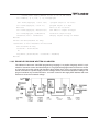
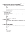
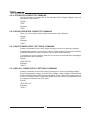
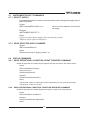
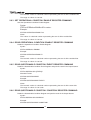
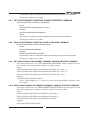
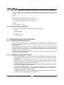
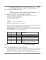
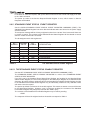
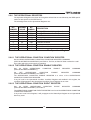
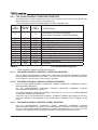
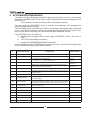
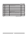
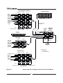
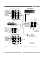
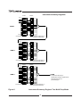
USER MANUAL FOR IEEE PROGRAMMING INTERFACE FOR GENESYSTM POWER SUPPLIES ,$5HY) 7KLVSDJHLQWHQWLRQDO\OHIWEODQN Table of Contents 1. THE DIGITAL (IEEE 488.2 SCPI) PROGRAMMING OPTION ..................................1 1.1 INTRODUCTION ...........................................................................................................................................1 1.2 SCOPE OF MANUAL.....................................................................................................................................1 1.3 CONFIGURATION .........................................................................................................................................1 1.4 GLOSSARY......................................................................................................................................................1 1.5 USING DIGITAL PROGRAMMING ...........................................................................................................2 1.5.1 THE IEEE-488.2 INTERFACE 2 1.6 POINT-TO-POINT MODE vs MULTI DROP MODE ................................................................................2 1.7 CONFIGURING THE IEEE INTERFACE ..................................................................................................3 1.7.1 SETTING THE POWER SUPPLY AND IEEE SELECT SWITCH 3 1.7.2 CONFIGURING THE IEEE CONTROLLER 3 1.8 CONFIGURING THE SUPPLIES.................................................................................................................4 1.9 THE INTERFACE INPUT BUFFER ............................................................................................................4 1.10 GETTING STARTED WITH THE SOFTWARE ....................................................................................4 1.10.1 EXAMPLE SESSION USING THE ‘IBIC’ CONSOLE 4 1.10.2 EXAMPLE PROGRAM WRITTEN IN VISUAL BASIC 5 1.10.3 EXAMPLE PROGRAM WRITTEN IN LABVIEW 6 2. PROGRAMMING COMMANDS ................................................................................7 2.1 COMMAND NOTES.......................................................................................................................................7 2.2 PROGRAMMING AND MESUREMENT COMMANDS ..........................................................................7 2.2.1 PROGRAM OUTPUT VOLTAGE 7 2.2.2 READ PROGRAMMED VOLTAGE COMMAND 8 2.2.3 MEASURE VOLTAGE COMMAND 8 2.2.4 PROGRAM OUTPUT CURRENT COMMAND 8 2.2.5 READ PROGRAMMED CURRENT COMMAND 8 2.2.6 MEASURE CURRENT COMMAND 9 2.2.7 ENABLE THE SUPPLY OUTPUT COMMAND 9 2.2.8 DISABLE THE SUPPLY OUTPUT COMMAND 9 2.2.9 READ OUTPUT ENABLE COMMAND 9 2.2.10 GO TO LOCAL MODE COMMAND 9 2.2.11 GO TO REMOTE MODE COMMAND 10 2.2.12 GO TO REMOTE WITH LOCAL LOCK OUT COMMAND 10 2.2.13 READ PROGRAMMING MODE COMMAND 10 2.3 GLOBAL OUTPUT COMMANDS .............................................................................................................10 2.3.1 USAGE 10 2.3.2 GLOBAL PROGRAM OUTPUT VOLTAGE 11 2.3.3 GLOBAL PROGRAM OUTPUT CURRENT 11 2.3.4 GLOBAL EANBLE THE SUPPLY OUTPUT COMMAND 11 2.3.5 2.3.6 2.3.7 2.3.8 GLOBAL DISABLE THE SUPPLY OUTPUT COMMAND GLOBAL RESET COMMAND GLOBAL SAVE POWER SUPPLY SETTINGS COMMAND GLOBAL RECALL POWER SUPPLY SETTINGS COMMAND 11 11 12 12 2.4 OUTPUT PROTECTION COMMANDS ...................................................................................................12 2.4.1 OVER VOLTAGE PROTECTION 12 2.4.2 CURRENT FOLD BACK PROTECTION 14 2.5 OPERATING CONDITION COMMANDS ...............................................................................................15 2.5.1 SYSTEM ERROR ENABLE COMMAND 15 2.5.2 READ SYSTEM ERROR COMMAND 15 2.5.3 READ SUPPLY OUTPUT MODE COMMAND 15 2.5.4 SET POWER SUPPLY POWER-UP MODE COMMAND 15 2.5.5 REPORT POWER SUPPLY POWER-UP MODE COMMAND 16 2.5.6 READ SCPI VERSION COMMAND 16 2.6 COMMON COMMANDS ............................................................................................................................16 2.6.1 CLEAR STATUS COMMAND 16 2.6.2 SET SERVICE REQUEST ENABLE COMMAND 16 2.6.3 READ SERVICE REQUEST ENABLE COMMAND 17 2.6.4 READ STATUS BYTE COMMAND 17 2.6.5 SET STANDARD EVENT STATUS ‘ENABLE’ REGISTER COMMAND 17 2.6.6 READ STANDARD EVENT STATUS ‘ENABLE’ REGISTER COMMAND 17 2.6.7 READ STANDARD EVENT STATUS ‘EVENT’ REGISTER COMMAND 18 2.6.8 READ IDENTITY COMMAND 18 2.6.9 RESET COMMAND 18 2.6.10 SELF TEST QUERY COMMAND 18 2.6.11 OPERATION COMPLETE COMMAND 19 2.6.12 READ OPERATION COMPLETE COMMAND 19 2.6.13 SAVE POWER SUPPLY SETTINGS COMMAND 19 2.6.14 RECALL POWER SUPPLY SETTINGS COMMAND 19 2.7 INSTRUMENT SELECT COMMANDS ....................................................................................................20 2.7.1 SELECT SUPPLY 20 2.7.2 READ SELECTED SUPPLY NUMBER 20 2.8 STATUS COMMANDS .................................................................................................................................20 2.8.1 READ OPERATIONAL CONDITION ‘EVENT’ REGISTER COMMAND 20 2.8.2 READ OPERATIONAL CONDITION ‘CONDITION’ REGISTER COMMAND 21 2.8.3 SET OPERATIONAL CONDITION ‘ENABLE’ REGISTER COMMAND 21 2.8.4 READ OPERATIONAL CONDITION ‘ENABLE’ REGISTER COMMAND 21 2.8.5 READ QUESTIONABLE CONDITION ‘EVENT’ REGISTER COMMAND 21 2.8.6 READ QUESTIONABLE CONDITION ‘CONDITION’ REGISTER COMMAND 21 2.8.7 SET QUESTIONABLE CONDITION ‘ENABLE’ REGISTER COMMAND 22 2.8.8 READ QUESTIONABLE CONDITION ‘ENABLE’ REGISTER COMMAND 22 2.8.9 SET QUESTIONABLE INSTRUMENT SUMMARY ‘ENABLE’ REGISTER COMMAND 22 2.8.10 READ QUESTIONABLE INSTRUMENT SUMMARY ‘ENABLE’ REGISTER COMMAND 22 2.8.11 READ QUESTIONABLE INSTRUMENT SUMMARY ‘EVENT’ REGISTER COMMAND 22 2.8.12 STATUS PRESET COMMAND 22 2.9 USING ERROR AND STATUS REGISTERS ............................................................................................23 2.9.1 OVERVIEW: REGISTER FAN-OUT 23 2.9.2 GLOSSARY OF REGISTER TERMS 23 2.9.3 CLEAR ALL STATUS REGISTERS 24 2.9.4 SERVICE REQUESTS AND STATUS BYTE REGISTER 24 2.9.5 STANDARD EVENT STATUS ‘EVENT’ REGISTER 25 2.9.6 2.9.7 2.9.8 THE OPERATIONAL REGISTERS THE QUESTIONABLE CONDITION REGISTERS THE SUMMARY REGISTERS 26 27 28 3. SYSTEM:ERROR MESSAGES...............................................................................29 List of Figures FIGURE 1. FIGURE 2. FIGURE 3. FIGURE 4. FIGURE 5. FIGURE 6. MULTI DROP POWER SUPPLIES CONFIGURATION ..................................................................2 IEEE CONNECTOR AND IEEE SELECT SWITCH LOCATION ...................................................3 IEEE SELECT SWITCH ..................................................................................................3 STATUS AND ERROR REGISTER TREE POINT-TO-POINT MODE.............................................31 STATUS AND ERROR REGISTER TREE MULTI DROP MODE ..................................................32 INSTRUMENT SUMMARY REGISTER TREE MULTI DROP MODE ..............................................33 List of Tables TABLE 1. THE STATUS BYTE REGISTER ............................................................................................................24 TABLE 2. THE STANDARD EVENT STATUS REGISTER...........................................................................................25 TABLE 3. THE OPERATIONAL REGISTERS ..........................................................................................................26 TABLE 4. THE QUESTIONABLE REGISTERS ........................................................................................................27 TABLE 5. SYSTEM ERROR CODES ...................................................................................................................29 NOTES .......................................................................................................................................................34 1. THE DIGITAL (IEEE 488.2 SCPI) PROGRAMMING OPTION 1.1 INTRODUCTION The internal factory installed GPIB interface allows to operate the GenesysTM Power Supply from a computer via IEEE-488 communication bus. The GPIB interface allows the user complete remote control of the power supply, including output voltage and current limit programming, setting the Over Voltage Protection, Under Voltage Limit and Foldback protection. The Output Voltage and Output Current can be measured and the power supply status can be monitored. Commands that are standard with digital programming include: % % % % 1.2 Program Voltage Measure Voltage Over-Voltage Shutdown IEEE-488.2 Compliant % % % % Program Current Measure Current Current Fold Back Shutdown SCPI Compliant SCOPE OF MANUAL This manual contains the information needed to operate the optional embedded digital interface used in the Power Supply. The interface is contained on one circuit card. It is optionally installed by the factory at the time of manufacture. 1.3 CONFIGURATION To operate on the IEEE 488.2 bus, each supply will require that an IEEE Programming Interface be installed. 1.4 GLOSSARY 1. The HOST PC will be the computer in control of the GEN supply(s) when operating under computer (Remote) control. 2. Point-to-Point Mode will mean that 1 IEEE Interface can control only 1 GEN supply. 3. Multi Drop Mode will mean that 1 IEEE Interface can control more than 1 GEN supply. 4. When in Multi Drop Mode the GEN supply with the IEEE Interface installed will be referred to as the Master Supply and all other attached supplies will be referred to as Slave Supplies. 5. A Communication Collision (AKA collision) is an event when in Multi Drop Mode more than 1 GEN supply attempts to transmit data simultaneously. 6. The Main micro. is the microprocessor installed on the GENESYS power supply control board that monitors/controls all power supply activity. 7. The IEEE micro. is the microprocessor installed on the IEEE Interface that is installed within the power supply. 8. Local Mode means that the supply under control of the “Front Panel Knob” or “Rear Panel Analog Remote” inputs. 9. Remote Mode means that the supply operating under direction of HOST PC/IEEE Interface via the IEEE488.2 Bus. Front panel does not operate except to view settings. 10. Serial Interface means that the Master supply is interfaced to the IEEE Interface via RS-232 digital communications and Slave supplies are interfaced to the IEEE Interface via RS485 daisy chain from the Master supply. This is done to activate Remote Control or to monitor supply activity while in Local Mode. 11. Instrument Summary Bit is a bit in an Instrument Summary Register (Ref. Figure 6 and 2.9.8.1) indicating the address of a supply that sent an SRQ. 1.5 1.5.1 USING DIGITAL PROGRAMMING THE IEEE-488.2 INTERFACE The IEEE-488 digital programming interface (also called the GPIB interface) is a popular way to connect instruments to a computer. It uses a specialized 24-pin cable with connectors that allow cables to be ‘stacked’ together. There are eight data wires; eight control wires and eight ground wires. If the system runs from a personal computer, there are numerous vendors of IEEE controller cards and software. The IEEE-488 standard has gone through several upgrades. The IEEE-488.1 focused on the handshaking of the eight control lines. The IEEE-488.2 added status registers inside each instrument and it added common commands to make programming groups RILQVWUXPHQWHDVLHU7KHODWHVWVSHFL¿FDWLRQ6&3,DGGVJXLGHOLQHVIRUWKHFRPPDQG syntax so one vendor’s power supply will use the same commands as another’s. The Interface follows all of these standards. Because many instruments may be connected and independently controlled by a single IEEE controller, each instrument must have a unique address. The IEEE controller automatically sets its address equal to the power supply address. 1.6 POINT-TO-POINT MODE vs MULTI DROP MODE Upon application of AC power to the Power Supply, the PS IEEE Interface will query the Power Supply to test if the Multi Drop installed. If the Multi Drop Option is installed, the IEEE Interface will activate the Multi-Drop mode (regardless of the number of units conQHFWHGWRWKH,(((,QWHUIDFH$QH[DPSOHRID0XOWL'URS3RZHU6XSSO\FRQ¿JXUDWLRQ is shown in Figure 1. . If the Multi Drop Option is not installed, the IEEE Interface will activate the Point-to-Point mode. When more than one Power Supply is connected to a single Power Supply with IEEE Interface (in Multi-Drop mode), all of the Power Supplies must have the Multi Drop Option LVLQVWDOOHG6HH)LJXUHIRUD0XOWL'URS3RZHU6XSSO\FRQ¿JXUDWLRQ )LJXUH 0XOWL'URS3RZHUVXSSOLHVFRQ¿JXUDWLRQ 1.7 1.7.1 CONFIGURING THE IEEE INTERFACE SETTING THE POWER SUPPLY AND IEEE SELECT SWITCH Power supply setting – set rear panel DIP switch (SW1) all contact to Down position. The interface contains a two position DIP switch that is accessible from the rear of the Power Supply and located next to the IEEE cable connector. Switch 2, located to the right of Switch1, is not used. Refer to Figure 2 for location of the IEEE connector and the IEEE select switch at the rear panel of the supply. IEEE select switch Figure 2. IEEE 488 connector IEEE Connector and IEEE Select Switch Location Placing Switch 1 in the ON Position, up, will activate this interface and deactivate the Power Supply’s Serial I/O capability. Placing Switch 1 in the OFF Position, down, will deactivate this interface and activate the Power Supply’s Serial (RS232 or RS485) I/O capability. The position of Switch 1 may be changed at any time; but the new setting will not take affect until the power is switched off and on. UP Down Figure 3. IEEE Select Switch 1.7.2 CONFIGURING THE IEEE CONTROLLER A typical IEEE controller is a personal computer with an IEEE interface card. Each card YHQGRUVXSSOLHVLWVRZQFRQ¿JXUDWLRQLQVWUXFWLRQVDQGLQWHUIDFHVRIWZDUH (DFKWLPHWKHVRIWZDUHLVH[HFXWHGWKHFRQWUROOHUPXVWEHFRQ¿JXUHGDVIROORZV Controller Address = 0. This is factory default for all controllers. EOI Flag = TRUE. The “End or Identify” is a control line in the IEEE cable that is asserted when the last character of a message string is sent. It is required for this interface. EOS Flag = FALSE: The “End of String”, used in some instruments to indicate the last character of a message, is not supported by this interface. 1.8 CONFIGURING THE SUPPLIES 1RFRQ¿JXUDWLRQLVUHTXLUHGIRUWKH0DVWHU6XSSO\7KH,(((,QWHUIDFHZLOODGDSWWKHDGdress of the Master Supply as its IEEE address. Slave supplies must be given a unique address that is different than the address of the Master supply. No two supplies may be given the same address. All Slave supplies must be set for RS485 operation at 19,200 Baud transmission rate. 1.9 THE INTERFACE INPUT BUFFER The Interface contains a 210 byte input buffer to save commands as they are received from WKH,(((EXV7KHEXIIHULVGLYLGHGLQWRIRXUWHHQE\WH¿HOGV7KXVWKHFRPPDQG 6285&(92/7$*($03/,78'(ZLOOFRQVXPH¿HOGV and the command: 92/7$*(ZLOOFRQVXPH¿HOGV The user may enter more than 1 concatenated command, separated by semicolons, to be executed. The interface will process all commands before returning any data/status to the IEEE bus or accepting any new commands to execute. Messages returned to the user will be the result of the last command executed. If a command error exists, or the Power Supply reports an error, all subsequent commands in the buffer will be terminated and the status returned to the user. ,IWKHXVHUHQWHUVPRUHWKDW¿HOGVDQHUURUZLOOEHJHQHUDWHG$OVRLIWKHXVHUHQWHUVPRUH WKDQE\WHVLQDQ\¿HOGDQHUURUZLOOEHJHQHUDWHG 1.10 GETTING STARTED WITH THE SOFTWARE A computer can use a variety of controllers, programs, and programming languages for the IEEE bus. Here is an example showing a minimal program to set the voltage, set the current and measure the voltage from a power supply. 1.10.1 EXAMPLE SESSION USING THE ‘IBIC’ CONSOLE $SRSXODUFRQVROHSURJUDPLV1DWLRQDO,QVWUXPHQWV³:LQ,QWHUDFWLYH&RQWURO´¿OHLELF exe). As the operator types each command on the computer, at the colon prompt, it is immediately sent to the power supply. This example works only for computers with National Instruments and compatible IEEE controller cards. Win32 Interactive Control Copyright 1996 National Instruments Corporation All rights reserved. Type ‘help’ for help or ‘q’ to quit. Controller address : ibdev Supply Address enter board index: 0 enter primary address: 6 enter secondary address: 0 enter timeout: 12 HQWHUµ(2,RQODVWE\WH¶ÀDJ enter end-of-string mode/byte: 10 Program supply to 100 volts output ud0: ibwrt “sour:volt 100” [0100] count: ( cmpl ) 12 Program supply to 5 amps output ud0: ibwrt “sour:curr 5” [0100] count: ( cmpl ) 11 Query: “What is output voltage?” ud0: ibwrt “meas:volt?” [0100] count: ( cmpl ) Read response 10 ud0: ibrd 50 [2100] count: 11 31 30 30 Supply reported output voltage ( end cmpl ) 2e 30 38 0a 1 0 0 . 0 8 . 1.10.2 EXAMPLE PROGRAM WRITTEN IN VISUAL BASIC Microsoft’s Visual Basic is a windows programming language that may be used to create “virtual instruments” and automation programs. Here is a simple program which sends commands to a power supply to set the voltage, set the current and measure the voltage. The program’s window only contains two items: a “Start” button and a text box to show the measured voltage. The syntax of the CALLed functions are correct only for National Instruments and compatible IEEE controllers. Don’t forget to add the forms “Ni-global.bas” and “Vbib-32.bas” to your project. Example Program Written in Visual Basic Option Explicit Dim SupplyUD As Integer ‘supply device descriptor Dim strMeasVolt As String * 50 ‘buffer for reading input message Private Declare Function GetTickCount Lib “kernel32” () As Long Private Sub cmdStart_Click() ‘start program here after “Start” button clicked ‘open IEEE port, get “User Device Description” = SupplyUD ‘assume power supply address is set to “6” on DIP switch Call ibdev(0, 6, 0, T3s, 1, 10, intSupplyUD) Call ibwrt(SupplyUD, “:volt 100”) ‘program output to 100 volts Call ibwrt(SupplyUD, “:curr 2”) ‘program output to 2 amps Wait 500 ‘wait 0.5 sec to settle Call ibwrt(SupplyUD, “meas:volt?”) ‘ask “What is output voltage?” Call ibrd(SupplyUD, strMeasVolt) ‘read back output voltage txtOutVolt.Text = strMeasVolt ‘display output voltage on window End Sub Private Sub Wait(mSecWait As Long) ‘subroutine to wait “mSecWait” milliseconds Dim StartTime As Long StartTime = GetTickCount Do Loop While (GetTickCount - StartTime < mSecWait) End Sub 1.10.3 EXAMPLE PROGRAM WRITTEN IN LABVIEW The National Instruments LabVIEW programming language is a popular language which is optimized for instrument control and data analysis. It is a graphical language where functions are shown DVLFRQVZLWKFRQQHFWLRQSRLQWVDQGGDWDÀRZVDORQJGUDZQOLQHV+HUHLVDVLPSOHSURJUDPZKLFK sends commands to a power supply to set the voltage, set the current and measure the voltage. The program’s window only contains two items: a numeric control for the supply IEEE address and a text indicator to show the measured voltage. 2. PROGRAMMING COMMANDS 2.1 COMMAND NOTES Expressions enclosed in square brackets, [ ], are optional and entered without the [ or ]. Expressions enclosed in greater than/less than, < >, are programming values and entered without the < or >. The expression <SP> represents a one character ASCII Space. In all commands upper case characters can be interchanged with lower case characters. 2.2 2.2.1 WORD CAN BE REPLACED WITH :AMPLITUDE :AMPL :CONDITION :COND :CURRENT :CURR :ENABLE :ENAB :ERROR? :ERR? :EVENT :EVEN GLOBAL GLOB INSTRUMENT INST :IMMEDIATE :IMM :ISUMMARY1 :ISUM1 :ISUMMARY2 :ISUM2 :ISUMMARY3 :ISUM3 :LEVEL :LEV :LIMIT :LIM MEASURE MEAS MODE? MOD? :NSELECT :NSEL :OPERATION :OPER :OUTPUT OUTP :PRESET :PRES :PROTECTION :PROT :QUESTIONABLE :QUES :SELECT :SEL SOURCE SOUR :STATE :STAT STATUS STAT SYSTEM SYST :TRIPPED :TRIP :VERSION :VERS :VOLTAGE :VOLT PROGRAMMING AND MESUREMENT COMMANDS PROGRAM OUTPUT VOLTAGE The output voltage can be programmed by sending the command: [SOURce]:VOLTage[:LEVel][:IMMediate][:AMPLitude]<SP> <value> where <value> is any valid voltage with or without a decimal place. Alternate Format: SOURCE:VOLTAGE<SP><value> :VOLTAGE:AMPLITUDE<SP><value> :VOLTAGE<SP><value> Examples: SOURCE:VOLTAGE:AMPLITUDE 15.77 :VOLTAGE 3.25 2.2.2 READ PROGRAMMED VOLTAGE COMMAND To read what voltage the supply was programmed to, regardless of the actual voltage, send the following command and read the response message. [SOURce]:VOLTage[:AMPLitude]? Alternate Format: SOURCE:VOLTAGE? :VOLTAGE:AMPLITUDE? :VOLTAGE? Examples: SOURCE:VOLTAGE:AMPLITUDE? :VOLTAGE? 2.2.3 MEASURE VOLTAGE COMMAND The output voltage can be measured by sending the command: MEASure:VOLTage? When the controller does the next IEEE Read, the interface will send the measured voltage to it. Example: MEASURE:VOLTAGE? 2.2.4 PROGRAM OUTPUT CURRENT COMMAND The output current is programmed by sending the command: [SOURce]:CURRent[:LEVel][:IMMediate][:AMPLitude]<SP><value> where < value > is any valid current with or without a decimal place. Alternate Formats: SOURCE:CURRENT<SP><value> :CURRENT:AMPLITUDE<SP><value> :CURRENT<SP><value> Examples: SOURCE:CURRENT:AMPLITUDE 15.77 :CURRENT 3.25 2.2.5 READ PROGRAMMED CURRENT COMMAND To read what current the supply was programmed to, regardless of the actual current, send the following command and read the response message. [SOURce]:CURRent[:AMPLitude]? Alternate Format: SOURCE:CURRENT? :CURRENT:AMPLITUDE? :CURRENT? Examples: SOURCE:CURRENT:AMPLITUDE? :CURRENT? 2.2.6 MEASURE CURRENT COMMAND The output current can be measured by sending the SCPI command: MEASure:CURRent? When the controller does the next IEEE Read, the supply will return the amperes of current being produced Example: MEASURE:CURRENT? 2.2.7 ENABLE THE SUPPLY OUTPUT COMMAND The power supply output can be turned on by sending this command: OUTPut:STATe<SP>1 The output will immediately jump to the last programmed voltage and current. Example: OUTPUT:STATE 1 Notes: 1 can be replaced with ON 2.2.8 DISABLE THE SUPPLY OUTPUT COMMAND The power supply output can be shut off by sending this command: OUTPut:STATe<SP>0 This command is equivalent to programming the output to zero volts. Example: OUTPUT:STATE 0 Notes: 0 can be replaced with OFF 2.2.9 READ OUTPUT ENABLE COMMAND Reads the Power Supply output enable. Places a 1 in the output queue if the supply is enabled and a 0 if the supply is disabled. Syntax: OUTPut:STATe? Example: OUTPUT:STATE? 2.2.10 GO TO LOCAL MODE COMMAND Places the supply under control of the Front Panel Controls. Syntax: SYSTem:SET<SP><0> Example: SYSTEM:SET 0 Notes: 0 can be replaced with LOC 2.2.11 GO TO REMOTE MODE COMMAND Places the supply under control of the IEEE Interface. Syntax: SYSTem:SET<SP><1> Example: SYSTEM:SET 1 Notes: 1 can be replaced with REM 2.2.12 GO TO REMOTE WITH LOCAL LOCK OUT COMMAND Places the supply under control of the IEEE Interface and disables the Front Panel Go To Local Button. Syntax: SYSTem:SET<SP><2> Example: SYSTEM:SET 2 Notes: 2 can be replaced with LLO 2.2.13 READ PROGRAMMING MODE COMMAND Reads the mode of the Power Supply. Place a 0 in the output queue if the supply is in Local Mode, a 1 if the supply is in Remote Mode and a 2 if the supply is in Remote Mode with Local Lock Out. Syntax: SYSTem:SET? Example: SYSTEM:SET? Returns: “LOC” “REM” ”LLO” 2.3 GLOBAL OUTPUT COMMANDS 2.3.1 USAGE % Global Commands are not SCPI compliant % Supplies acting upon Global Commands need not be a currently addressed supply % All supplies attached to the Interface must be capable of accepting Global Commands % No messages, OPC or Not Busy will be returned to the HOST PC after a Global Command has been issued. The Busy Bit of the Status Byte, see Figure 1 and Figure 2, will be set to 0 after this command is issued. % It will be the responsibility of the User Software to add a 200 Ms delay after each Global Command is issued and before any other command can be issued. 2.3.2 GLOBAL PROGRAM OUTPUT VOLTAGE The output voltage of all supplies can be programmed by sending the command: GLOBal:VOLTage[:LEVel][:IMMediate][:AMPLitude]<SP> <value> where <value> is any valid voltage with or without a decimal place. Alternate Format: none Example: GLOBAL:VOLTAGE:AMPLITUDE 15.77 2.3.3 GLOBAL PROGRAM OUTPUT CURRENT The output current of all supplies are programmed by sending the command: GLOBALCURRent[:LEVel][:IMMediate][:AMPLitude]<SP><value> where < value > is any valid current with or without a decimal place. Alternate Formats: none Examples: GLOBal:CURRENT:AMPLITUDE 15.77 2.3.4 GLOBAL EANBLE THE SUPPLY OUTPUT COMMAND All power supply outputs can be turned on by sending this command: GLOBal:OUTPut:STATe<SP>1 The output will immediately jump to the last programmed voltage and current. Example: GLOBAL:OUTPUT:STATE 1 Notes: 1 can be replaced with ON 2.3.5 GLOBAL DISABLE THE SUPPLY OUTPUT COMMAND All power supply outputs can be shut off by sending this command: GLOBal:OUTPut:STATe<SP>0 This command is equivalent to programming the output to zero volts. Example: GLOBAL:OUTPUT:STATE 0 Notes: 0 can be replaced with OFF 2.3.6 GLOBAL RESET COMMAND Resets all Power Supplies. Voltage and current are set to 0. Supply output is set to OFF. Supply enters Remote Mode Operation. Syntax: GLOBal:*RST Example: GLOBal:*RST 2.3.7 GLOBAL SAVE POWER SUPPLY SETTINGS COMMAND Sends a command to all Power Supplies causing them to save their operating settings: Programmed voltage, Current, Over Voltage, Under Voltage, Remote/Local Mode, Auto/Safe Restart, Current Fold Back, etc. can be stored in Memory. To change one or more settings, enter the one or more commands with new settings and then enter this command. Syntax: GLOBal:*SAV<SP><0> Example: GLOBAL:*SAV 0 2.3.8 2.4 GLOBAL RECALL POWER SUPPLY SETTINGS COMMAND Sends a command to all Power Supplies causing them to recall their operating settings: Recall Programmed voltage, Current, Over Voltage, Under Voltage, Remote/Local Mode, Auto/Safe Restart and Current Fold Back. If the output of the supply was set to an OFF condition by the Front Panel Button before the *RCL command was sent, the supply will remain in the OFF state. Syntax: GLOBal :*RCL<SP><0> Example: GLOBAL :*RCL 0 OUTPUT PROTECTION COMMANDS 2.4.1 OVER VOLTAGE PROTECTION 2.4.1.1 SET THE OVER VOLTAGE PROTECTION LEVEL COMMAND Set the over voltage protection level of the Power Supply to <value>, where <value> is a number between zero and the maximum supply output voltage. A decimal point is optional. Syntax: [SOURce]:VOLTage:PROTection:LEVel<SP><value> Alternate Format: :VOLTAGE:PROTECTION:LEVEL<SP><value> Examples: SOURCE:VOLTAGE:PROTECTION:LEVEL 25.00 SOURCE:VOLTAGE:PROTECTION:LEVEL MAX Notes: If <value> equals MAX, the supply will set its over voltage to its maximum level. 2.4.1.2 READ THE OVER VOLTAGE PROTECTION LEVEL COMMAND Read the over voltage protection level of the Power Supply. Syntax: [SOURce]:VOLTage:PROTection:LEVel? Alternate Format :VOLTAGE:PROTECTION:LEVEL? Example: SOURCE:VOLTAGE:PROTECTION:LEVEL? 2.4.1.3 READ OVER VOLTAGE TRIPPED STATE COMMAND Read if the Power Supply over voltage has tripped. Syntax: [SOURce]:VOLTage:PROTection:TRIPped? Alternate Format: :VOLTAGE:PROTECTION:TRIPPED? Example: SOURCE:VOLTAGE:PROTECTION:TRIPPED? Read the response number. The normal response is “0” (zero). If a “1” (one) is returned, an over voltage has occurred and the output is shut down. 2.4.1.4 SET THE UNDER VOLTAGE PROTECTION LEVEL COMMAND Set the under voltage protection level of the Power Supply. Syntax: [SOURce]:VOLTage:LIMit:LOW<SP><value> Alternate Format: :VOLTAGE:LIMIT:LOW<SP><value> Example: SOURCE:VOLTAGE:LIMIT:LOW 25.00 2.4.1.5 READ THE UNDER VOLTAGE PROTECTION LEVEL COMMAND Read the under voltage protection level of the Power Supply. Syntax: [SOURce]:VOLTage:LIMit:LOW? Alternate Format :VOLTAGE:LIMIT:LOW? Example: SOURCE:VOLTAGE:LIMIT:LOW? 2.4.2 CURRENT FOLD BACK PROTECTION 2.4.2.1 SET CURRENT FOLD BACK PROTECTION COMMAND Turn on the current fold back protection of the Power Supply. Syntax: [SOURce]:CURRent:PROTection:STATe<SP><1> Alternate Format: :CURRENT:PROTECTION:STATE<SP>1 Example: SOURCE:CURRENT:PROTECTION:STATE 1 2.4.2.2 CLEAR CURRENT FOLD BACK PROTECTION COMMAND Turn off the current fold back protection of the Power Supply. Syntax: [SOURce]:CURRent:PROTection:STATe<SP><0> Alternate Format: :CURRENT:PROTECTION:STATE<SP>0 Example: SOURCE:CURRENT:PROTECTION:STATE 0 2.4.2.3 READ CURRENT FOLD BACK STATE COMMAND Read if the Fold back is enabled or disabled. The interface will return an ON if Fold Back Protection is set or an OFF if not set. Syntax: [SOURce]:CURRent:PROTection:STATe? Alternate Format: :CURRENT:PROTECTION:STATE? Example: SOURCE:CURRENT:PROTECTION:STATE? 2.4.2.4 READ FOLD BACK TRIPPED STATE COMMAND Read if the Power Supply Current Fold Back has tripped. The interface will return a 1 if Fold Back Protection has tripped or a 0 if not tripped. Syntax: [SOURce]:CURRent:PROTection:TRIPped? Alternate Format: :CURRENT:PROTECTION:TRIPPED? Example: SOURCE:CURRENT:PROTECTION:TRIPPED? 2.5 OPERATING CONDITION COMMANDS 2.5.1 SYSTEM ERROR ENABLE COMMAND Clears the Error Queue and enables all error messages to be placed in the System Error Queue. Refer to Section 3 : SYSTEM:ERROR MESSAGES for details Syntax: SYSTem:ERRor:ENABle Action: Direct the interface to save error messages. Example: SYSTEM:ERROR:ENABLE 2.5.2 READ SYSTEM ERROR COMMAND The oldest error message is removed from the Error Queue and placed in the Output Queue. If the Error Queue was empty, a 0 is placed in the Output Queue. Syntax: SYSTem:ERRor? Example: SYSTEM:ERROR? Returned Message Example: -222, “Data out of range” 2.5.3 READ SUPPLY OUTPUT MODE COMMAND Read if the Power Supply is in the Constant Voltage, Constant Current or Output Off Mode. The interface will return a CV if the supply is in Constant Voltage Mode, a CC if the supply is in Constant Current Mode or an OFF if the supply output is off. Syntax SOURce:MODe?: Example: SOURCE:MODE?: Returns: CV CC or OFF 2.5.4 SET POWER SUPPLY POWER-UP MODE COMMAND Set the Power Supply for Auto-Restart or Safe-Start operation upon power up. Syntax: OUTPut:PON<SP><value> where value = 0 or OFF for Safe-Start or value = 1 or ON for Auto-Restart Examples: OUTPUT:PON 0, OUTPUT:PON 1 Notes: This command is in addition to the SCPI compliance requirements. 2.5.5 REPORT POWER SUPPLY POWER-UP MODE COMMAND Report the Power Supply Auto-Restart or Safe-Start operation upon power up mode. The interface will return an ON if the supply is Auto-restart operation or an OFF if the supply is in SafeStart operation Syntax: OUTPut:PON? Example: OUTPUT:PON? Notes: This command is in addition to the SCPI compliance requirements. 2.5.6 READ SCPI VERSION COMMAND Read the SCPI Compliance year that this interface adheres to. Syntax: SYSTem:VERSion? Example: SYSTEM:VERSION? 2.6 COMMON COMMANDS 2.6.1 CLEAR STATUS COMMAND Clears all event registers and stored error messages. Relays the command to the Power Supply Syntax: *CLS Example: *CLS 2.6.2 SET SERVICE REQUEST ENABLE COMMAND Set the Service Request Enable Register. Syntax: *SRE<SP><value> Example: *SRE 140 Notes: <value> is a decimal number representing the sum of all the enabled bits. The range of <value> is 0 to 255. 2.6.3 READ SERVICE REQUEST ENABLE COMMAND Read the value of the Service Request Enable Register. Syntax: *SRE? Example: *SRE? Notes: The returned <value> is a decimal number representing the sum of all the enabled bits. The range of <value> is 0 to 255. 2.6.4 READ STATUS BYTE COMMAND Read the value of the Status Register. The Status Byte Register contains eight bits which are set to show that some other register has recorded an event or an error. See Table 1. The response to this query will be a binary weighted number from 0 to 255. Syntax: *STB? Example: *STB? Notes: The returned <value> is a decimal number representing the sum of all the bits. The range of <value> is 0 to 255. 2.6.5 SET STANDARD EVENT STATUS ‘ENABLE’ REGISTER COMMAND Set Event Status Enable Register to a value. See Table 2 . Syntax: *ESE<SP><value> Example: *ESE 74 Notes: <value> is a decimal number representing the sum of all the enabled bits. The range of <value> is 0 to 255. 2.6.6 READ STANDARD EVENT STATUS ‘ENABLE’ REGISTER COMMAND Read the value of the Event Status Enable Register. See Table 2. Syntax: *ESE? Example: *ESE? Notes: The returned <value> is a decimal number representing the sum of all the enabled bits. The range of <value> is 0 to 255. 2.6.7 READ STANDARD EVENT STATUS ‘EVENT’ REGISTER COMMAND Read the value of the Event Status Register. See Table 2 Figure 4 Figure 5 and Figure 6. Syntax: *ESR? Example: *ESR? Notes: The returned <value> is a decimal number representing the sum of all the enabled bits. The range of <value> is 0 to 16,767. 2.6.8 READ IDENTITY COMMAND Read Company Logo, Power Supply range, Serial Number and Revision of the Power Supply and Version of this IEEE Interface. When the controller reads the output from the power supply, a single-line identity string will be returned. A typical identity string format is: Manufacturer/Model <max volt>-<max curr>, S/N <supply serial>, REV <power supply revisionIEEE interface version> Syntax: *IDN? Example: *IDN? Return message example: Lambda, 6-200, S/N 11111-111111, REV:1U:3.0-D 2.6.9 RESET COMMAND Resets the Power Supply. Voltage and current are set to 0. Supply output is set to OFF. Supply enters Remote Mode Operation. Syntax: *RST Example: *RST 2.6.10 SELF TEST QUERY COMMAND Test that the Interface and the Power Supply are operational. This will be accomplished by sending a measure voltage command to the power supply. The result of the measure voltage command is ignored. The result will be tested for completion and/or error. Syntax: *TST? Example: *TST? Return message example: “0” if supply test pass “1” if supply test fail 2.6.11 OPERATION COMPLETE COMMAND Set the Operation Complete Bit in the Standard Event Status Register when all RSHUDWLRQVKDYH¿QLVKHG Syntax: *OPC Example: *OPC 2.6.12 READ OPERATION COMPLETE COMMAND 3ODFHDLQWKH2XWSXW4XHXHZKHQDOORSHUDWLRQVKDYH¿QLVKHG Syntax: *OPC? Example: *OPC? 2.6.13 SAVE POWER SUPPLY SETTINGS COMMAND Sends a command to the Power Supply causing it to save its operating settings: Programmed voltage, Current, Over Voltage, Under Voltage, Remote/Local Mode, Auto/Safe Restart, Current Fold Back, etc. can be stored in Memory. To change one or more settings, enter the one or more commands with new settings and then enter this command. Syntax: *SAV<SP><0> Example: *SAV 0 2.6.14 RECALL POWER SUPPLY SETTINGS COMMAND Sends a command to the Power Supply causing it to recall its operating settings: Recall Programmed voltage, Current, Over Voltage, Under Voltage, Remote/Local Mode, Auto/Safe Restart and Current Fold Back. If the output of the supply was set to an OFF condition by the Front Panel Button before the *RCL command was sent, the supply will remain in the OFF state. Syntax: *RCL<SP><0> Example: *RCL 0 2.7 INSTRUMENT SELECT COMMANDS 2.7.1 SELECT SUPPLY Commands Interface to conduct communications with a designated supply when in Multi Drop Mode. Syntax: INSTrument:NSELect<SP><nn> where nn is the address of the selected supply Example: INSTRUMENT:SELECT 17 Notes: Upon power up the Master Supply will be automatically selected. :NSELect may be replaced with :SELect 2.7.2 READ SELECTED SUPPLY NUMBER Syntax: INSTrument:NSELect? Notes: Returns the selected .Supply number ’xx’ 2.8 STATUS COMMANDS 2.8.1 READ OPERATIONAL CONDITION ‘EVENT’ REGISTER COMMAND Reads the Operational Condition Event Register and puts the result in the Output Queue. Syntax: STATus:OPERation[:EVENt]? Alternate Format: STATUS:OPERATION? Example: STATUS:OPERATION:EVENT? Notes: The returned <value> is a decimal number representing the sum of all the event bits. The range of <value> is 0 to 255. 2.8.2 READ OPERATIONAL CONDITION ‘CONDITION’ REGISTER COMMAND Reads the Operational Condition Register and puts the result in the Output Queue. Syntax: STATus:OPERation:CONDition? Example: STATUS:OPERATION:CONDITION? Notes: The returned <value> is a decimal number representing the sum of all the condition bits. The range of <value> is 0 to 255. 2.8.3 SET OPERATIONAL CONDITION ‘ENABLE’ REGISTER COMMAND Sets the Operational Condition Enable Register. Syntax: STATus:OPERation:ENABle<SP><value> Example: STATUS:OPERATION:ENABLE 53 Notes: The <value> is a decimal number representing the sum of all the enabled bits. The range of <value> is 0 to 255. 2.8.4 READ OPERATIONAL CONDITION ‘ENABLE’ REGISTER COMMAND Reads the Operational Condition Enable Register. Syntax: STATus:OPERation:ENABle? Example: STATUS:OPERATION:ENABLE? Notes: The returned <value> is a decimal number representing the sum of all the enabled bits. The range of <value> is 0 to 255. 2.8.5 READ QUESTIONABLE CONDITION ‘EVENT’ REGISTER COMMAND Reads the Questionable Condition Event Register and puts the result in the Output Queue. Syntax: STATus:QUEStionable [:EVENt]? Alternate Format: STATUS:QUESTIONABLE? Example: STATUS:QUESTIONABLE:EVENT? Notes: The returned <value> is a decimal number representing the sum of all the event bits. The range of <value> is 0 to 4,095. 2.8.6 READ QUESTIONABLE CONDITION ‘CONDITION’ REGISTER COMMAND Reads the Questionable Condition Register and puts the result in the Output Queue. Syntax: STATus:QUEStionable:CONDition? Example: STATUS:QUESTIONABLE:CONDITION? The returned <value> is a decimal number representing the sum of all the event bits. The range of <value> is 0 to 4,095. 2.8.7 SET QUESTIONABLE CONDITION ‘ENABLE’ REGISTER COMMAND Sets the Questionable Condition Enable Register. Syntax: STATus:QUEStionable:ENABle<SP><value> Example: STATUS:QUESTIONABLE:ENABLE 53 Notes: The <value> is a decimal number representing the sum of all the enabled bits. The range of <value> is 0 to 4,095. 2.8.8 READ QUESTIONABLE CONDITION ‘ENABLE’ REGISTER COMMAND Reads the Questionable Condition Enable Register. Syntax: STATus:QUEStionable:ENABle? Example: STATUS:QUESTIONABLE:ENABLE? The returned <value> is a decimal number representing the sum of all the event bits. The range of <value> is 0 to 4,095. 2.8.9 SET QUESTIONABLE INSTRUMENT SUMMARY ‘ENABLE’ REGISTER COMMAND See Figure 6 and Section 2.9.8, THE SUMMARY REGISTERS. Enable an SRQ from a supply to set Bit 0 of the Questionable Condition ‘condition’ register. Syntax: STATus:QUEStionable:INSTrument:ISUMmary1:ENABle<SP><value> or STATus:QUEStionable:INSTrument:ISUMmary2:ENABle<SP><value> or STATus:QUEStionable:INSTrument:ISUMmary3:ENABle<SP><value> Example: STAT:QUES:INST:ISUM1:ENAB 122 Action: Enable supplies #0, 2, 3, 4 and 5 to set bit 0 of the Questionable Condition ‘condition’ register. 2.8.10 READ QUESTIONABLE INSTRUMENT SUMMARY ‘ENABLE’ REGISTER COMMAND See Figure 6 and Section 2.9.8, THE SUMMARY REGISTERS. Read which supplies can set Bit 0 of the Questionable Condition ‘condition’ register by sending an SRQ. Syntax: STATus:QUEStionable:INSTrument:ISUMmary1:ENABle? or STATus:QUEStionable:INSTrument:ISUMmary2:ENABle? or STATus:QUEStionable:INSTrument:ISUMmary3:ENABle? Example: STAT:QUES:INST:ISUM1:ENAB? 2.8.11 READ QUESTIONABLE INSTRUMENT SUMMARY ‘EVENT’ REGISTER COMMAND See Figure 6 and Section 2.9.8, THE SUMMARY REGISTERS. Read which supplies sent an SRQ. These bits are set regardless of the value of the enable bit. When set they remain set until read. Syntax: STATus:QUEStionable:INSTrument:ISUMmary1? or STATus:QUEStionable:INSTrument:ISUMmary2? or STATus:QUEStionable:INSTrument:ISUMmary3? Example: STAT:QUES:INST:ISUM1? 2.8.12 STATUS PRESET COMMAND Presets all Operation Enable and Questionable Enable Registers. Syntax: STATus:PRESet Example: STATUS:PRESET 2.9 USING ERROR AND STATUS REGISTERS 2.9.1 OVERVIEW: REGISTER FAN-OUT 7KH ,((( ,QWHUIDFH ERDUG KDV D VHW RI VWDWXV DQG HUURU UHJLVWHUV 7KH\ DUH GH¿QHG E\ WKH ,(((VSHFL¿FDWLRQDVSDUWRIWKH,(((&RPPRQ&RPPDQGVHWUHTXLUHGE\DOOFRPpliant instruments. These registers allow the IEEE controller to examine the operational state of the supply in detail. A “fan-out” architecture is used so only one summary register needs to be read to know if an HYHQWRFFXUUHGLQDQ\RWKHUUHJLVWHU7KLVIDQRXWDOORZVDXWRPDWLFWHVWSURJUDPVWRHI¿FLHQWO\ manage the remote programming mode. A diagram of the register structure is shown in Figure 4 for Point-to-Point Mode and in Figure 5 and Figure 6 for Multi Drop Mode. 2.9.2 GLOSSARY OF REGISTER TERMS SERVICE REQUEST: When an instrument on the IEEE bus asserts the SRQ line in the cable, it tells the controller that it has completed its task or that an error has occurred. SERIAL POLL: An IEEE function which reads back the data in an instrument’s Status Byte Register. The controller should perform this function after every command to verify the command was successful. REGISTER QUERIES: Read the contents of registers. The contents are returned as a binary weighted decimal number. CONDITIONAL REGISTERS. These contain bits that are set when a condition or error occurs. The bits are only cleared when the condition or error is cleared. The contents may be read but not changed. ENABLE REGISTERS: The various Enable Registers can be set to allow the status and errors to be detectable by a Serial Poll. EVENT REGISTERS: These contain bits that are set when an event or error occurs. The bits are cleared when the contents of the register are queried. 2.9.3 CLEAR ALL STATUS REGISTERS *CLS This command clears all event registers and stored error messages. It will not affect the Conditional, Instrument Summary or the Enable registers. 2.9.4 SERVICE REQUESTS AND STATUS BYTE REGISTER The Status Byte Register contains the bits that are set when an event occurs in: Questionable Condition Event Register, Operational Condition Event Register, Standard Event Status Register, or when a message is available in the Output Queue or when an Error Message is available in the Error Queue. If any of these bits are set, and the corresponding bit is set in the Service Request Enable Register the Service Request Bite (SRQ) bit will become set. The SRQ bit will assert a signal onto the Service Request (SRQ) line in the IEEE cable. The controller program can detect the SRQ, read what the problem is from the power supply, and clear the SRQ. The bit assignments for the Status Byte Register are: BIT NUMBER 0 1 2 3 DECIMAL VALUE 1 2 4 8 BIT SYMBOL BSY 0 SYS QUE 4 16 MAV Message Available in Output Que. Set after query message is received 5 32 ESB Standard Event Summary 6 64 RQS Request For Service. Is set if SYS, QUE, MAV, ESB and/or OPR is enabled and set. 7 128 OPR Operational Summary DESCRIPTION 1 = Busy, 0 = Ready Not Used System Error, Message Available in Error Que. Questionable Summary Table 1. The Status Byte Register 2.9.4.1 THE SERVICE REQUEST ENABLE REGISTER See the SET SERVICE REQUEST ENABLE COMMAND (*SRE). With two exceptions, the Service Request Enable Register is a mirror of the Status Byte Register. Bit 0 (Busy) and Bit 6 (SRQ) will be ignored. Also note that Bits 1 is not used in this interface and will have no effect. To enable a Service Request, the user should refer to Table 1 and determine which events need to be enabled to cause the request, add up the decimal value for those events and supply that value to the *SRE command. The power up value of the Service Request Enable Register is zero, which means no Service Requests are Enabled. 2.9.5 STANDARD EVENT STATUS ‘EVENT’ REGISTER See the READ STANDARD EVENT STATUS ‘EVENT’ REGISTER COMMAND (*ESR?). The Standard Event Status Register has seven bits that indicate status and errors for the power supply and the interface. The response message will be a binary weighted number from 0 to 255. Zero is returned if there are no errors or events. The contents of the Standard Event Status Register will be cleared to zeroes after the *ESR? Command is executed. The bit assignments for this register are: BIT NUMBER DECIMAL VALUE BIT SYMBOL 0 1 2 3 4 5 6 7 1 2 4 8 16 32 64 128 OPC 0 QYE DDE EXE CME 0 PON Table 2. DESCRIPTION Operation complete Not used. Query Error Device Dependant Error, Fault Shutdown Execution Error Command Error Not used Power On. Set when power is switched on. The Standard Event Status Register 2.9.5.1 THE STANDARD EVENT STATUS ‘ENABLE’ REGISTER See the SET STANDARD EVENT STATUS ‘ENABLE’ REGISTER COMMAND (*ESE). The STANDARD EVENT STATUS ‘ENABLE’ REGISTER is a mirror of the STANDARD EVENT STATUS ‘EVENT’ REGISTER. If any bit is set in the Standard Event Status Event Register and enabled in the Standard Event Status Enable Register, the event will propagate to the Status Byte Register as a Standard Event Summary. By writing a binary weighted value to the Standard Event Status Enable Register, the bits in the Standard Event Status Event Register may be individually enabled so only selected events will cause a service request. The power-up default is all zeroes in the enable register. This means no status or errors will be sent to the Status Byte Register. However, even if no bits are enabled, the contents of the Standard Event Status Register may always be read with the *ESR? query. The contents of the Standard Event Enable Register may be read by sending: *ESE? The response will be a bit weighted number whose bits correspond to Table 2 2.9.6 THE OPERATIONAL REGISTERS 7KH2SHUDWLRQDO5HJLVWHUVDUHWKUHHELWUHJLVWHUVZKRVHELWVDUHQRWGH¿QHGE\WKH,(((VSHFL¿FDWLRQEXWDUHVSHFL¿FWRWKH,(((GHYLFH The bit assignments for the Operational Registers are: BIT NUMBER DECIMAL VALUE BIT SYMBOL DESCRIPTION 0 1 2 3 4 1 2 4 8 16 CV CC NFLT 0 AST Set high if Constant Voltage Operation Set high if Constant Current Operation No fault Not used Auto Start Enabled 5 64 FBE Foldback Enabled 6 7 8 to 15 64 128 N/A 0 LOC 0 Not Used Remote/Local Mode Not used Table 3. The Operational Registers 2.9.6.1 THE OPERATIONAL CONDITION ‘CONDITION’ REGISTER See the READ OPERATIONAL CONDITION ‘CONDITION’ REGISTER COMMAND 67$78623(5$7,21&21',7,21"DQG7DEOH7KHELWVDVOLVWHGLQ7DEOHUHÀHFWWKHFRQGLtions under which the power supply is operating. 2.9.6.2 THE OPERATIONAL CONDITION ‘ENABLE’ REGISTER See the READ OPERATIONAL CONDITION ‘ENABLE’ REGISTER COMMAND (STATUS:OPERATION:ENABLE?), the SET OPERATIONAL CONDITION ‘ENABLE’ REGISTER COMMAND (STATUS:OPERATION:ENABLE) and Table 3. The OPERATIONAL CONDITION ‘ENABLE’ REGISTER is a mirror of the OPERATIONAL CONDITION ‘CONDITION’ REGISTER. If any bit is set in the Operational Condition ‘Condition’ Register and enabled in this register, the condition will propagate to the Operational Condition ‘Event’ Register as an event. 2.9.6.3 THE OPERATIONAL CONDITION ‘EVENT’ REGISTER See the READ OPERATIONAL CONDITION ‘EVENT’ REGISTER COMMAND (STATUS:OPERATION:EVENT?) and Table 3. The OPERATIONAL CONDITION ‘EVENT’ REGISTER is a mirror of the OPERATIONAL CONDITION ‘CONDITION’ REGISTER. If any event is set in this Register, it will propagate to the Status Byte Register as an Operational Summary event. 2.9.7 THE QUESTIONABLE CONDITION REGISTERS 7KH4XHVWLRQDEOH&RQGLWLRQ5HJLVWHUVDUHWKUHHELWUHJLVWHUVZKRVHELWVDUHQRWGH¿QHGE\WKH ,(((VSHFL¿FDWLRQEXWDUHVSHFL¿FWRWKH,(((GHYLFH The bit assignments for the Questionable Condition Registers are: BIT NUMBER DECIMAL VALUE BIT SYMBOL 0 1 0 1 2 3 4 5 6 7 8 9 10 11 12 to 15 2 4 8 16 32 64 128 256 512 1024 2048 N/A AC OTP FLD OVP SO OFF ENA INPO INTO ITMO ICOM 0 DESCRIPTION Not used in Point-to-Point Mode Instrument Summary in Multi Drop Mode AC Fail Over Temperature Fold Back Protect Over Voltage Protection Shut Off Output Off Output Enable ,QWHUQDO,QSXW2YHUÀRZ ,QWHUQDO2YHUÀRZ Internal Time Out * Internal Comm Error * Not used Table 4. The Questionable Registers *: Event registers, reading will clear the event bit. 2.9.7.1 THE QUESTIONABLE CONDITION ‘CONDITION’ REGISTER See the READ QUESTIONABLE CONDITION ‘CONDITION’ REGISTER COMMAND (STATUS: 48(67,21$%/(&21',7,21"DQG7DEOH7KHELWVDVOLVWHGLQ7DEOHUHÀHFWWKHTXHVWLRQDEOH error conditions under which the power supply is operating. 2.9.7.2 THE QUESTIONABLE CONDITION ‘ENABLE’ REGISTER See the READ QUESTIONABLE CONDITION ‘ENABLE’ REGISTER COMMAND (STATUS: QUESTIONABLE:ENABLE?), the SET QUESTIONABLE CONDITION ‘ENABLE’ REGISTER COMMAND (STATUS: QUESTIONABLE:ENABLE) and Table 4. The QUESTIONABLE CONDITION ‘ENABLE’ REGISTER is a mirror of the QUESTIONABLE CONDITION ‘CONDITION’ REGISTER. If any bit is set in the Questionable Condition ‘Condition’ Register and enabled in this register, the condition will propagate to the Questionable Condition ‘Event’ Register as an event. 2.9.7.3 THE QUESTIONABLE CONDITION ‘EVENT’ REGISTER See the QUESTIONABLE CONDITION ‘EVENT’ REGISTER COMMAND (STATUS: QUESTIONABLE:EVENT?) and Table 4.The QUESTIONABLE CONDITION ‘EVENT’ REGISTER is a mirror of the QUESTIONABLE CONDITION ‘CONDITION’ REGISTER. If any event is set in this Register, it will propagate to the Status Byte Register as a Questionable Summary event. 2.9.8 THE SUMMARY REGISTERS 2.9.8.1 INSTRUMENT SUMMARY 1/2/3 The INSTRUMENT SUMMARY EVENT REGISTER, ISUM1 through ISUM3 (see Figure 6), will record the address of the supply causing an SRQ. These are ‘EVENT’ registers and the bits will remain set until read by the STAT:QUES:INST:ISUMn command. They are always enabled. 3. SYSTEM:ERROR MESSAGES The Status and Error Registers described in the previous section is only one of the status methods in the IEEE board. There is also a SCPI requirement for error messages that are in the form of: <Error Number><Comma><Quote><Error Description><Quote> The user sends the “SYST:ERR?” query to read the error message. The messages are VWRUHGLQD¿UVWLQ¿UVWRXWTXHXH The SYST:ERR queue can buffer up to TEN error messages, although the tenth is replaced E\WKH±´4XHXH2YHUÀRZ´LIDQHOHYHQWKPHVVDJHLVJHQHUDWHG$IWHUWKHTXHXHRYHUÀRZRQO\WKH¿UVWWHQPHVVDJHVDUHVWRUHGDQGWKHODWHUPHVVDJHVDUHORVW The SYST:ERR queue is cleared by: A. Reading the messages one at a time using “SYST:ERR?” until 0, ”No error” is read. B. The *CLS (Clear Status) command. C. Sending SYSTEM:ERROR:ENABLE command. If any message is in the SYST:ERR queue (except “No error”), then bit 2 of the Status Byte is set. A Service Request is generated if enabled. ERROR # 0 ERROR EVENT ERROR DESCRIPTION “No error” No error reported -100 “Command error” ,(((UHFHLYHVFRPPDQGZLWKXQVSHFL¿HGHUURU -101 “Invalid Character” A character was received that is not: a-z, A-Z, 0-9, ?, *, :, ;,period, space, CR, LF -102 “Syntax error” IEEE receives unrecognized command word -104 “Data type error” -109 ERROR EXAMPLE receives letter where number expected. V%LT 50 VOLT, 50 BEAS:VOLT? VOLTS 150 CURRENT NA OUTPUT DC “Missing parameter” Valid command received but not enough parameters. VOLT -112 “Program word too long” Command word had more than 14 characters before separator (space or colon) was found MEASUREVOLTAGE? -222 “Data out of range” Attempt to program voltage, current or OVP beyond supply limits -241 “Hardware Missing” When operating in Multi Drop mode, an attempt was made to address a non-existent supply. -350 ³4XHXH2YHUÀRZ´ Too many SYST:ERR messages are stored in this queue and the newest messages are discarded. The Max. number of stored messages is 10. +300 “Execution error” General execution error. +301 “PV above OVP” Attempt to program voltage above OVP setting. +302 “PV below UVL” Attempt to program voltage below UVL setting. +304 “OVP below PV” Attempt to set OVP below voltage setting. +306 “UVL above PV” Attempt to set UVL above voltage setting. +307 “On during fault” Attempt to set supply output “ON” when a fault exists +320 “Fault shutdown” *HQHUDOPHVVDJHIRUQRQVSHFL¿HGVKXWGRZQ IEEE receives command parameter with wrong type of data. Example: +321 “AC fault shutdown” Brown-out or phase-loss shutdown occurred +322 “Over-Temperature shutdown” Over-temperature shutdown occurred +323 “Fold-Back shutdown” Fold-Back shutdown occurred +324 “Over-Voltage shutdown” Over-Voltage shutdown occurred +325 “Analog shut-off shutdown” Shut-Off occurred from rear panel J1 +326 “Output-Off shutdown” Output-Off occurred from front panel button +327 “Enable Open shutdown” Enable Open occurred from rear panel J1 +340 “Internal message fault” *HQHUDOQRQVSHFL¿HG,QWHUQDOPHVVDJHIDXOW +341 ³,QSXWRYHUÀRZ´ IEEE receive data buffer is too full. +342 ³,QWHUQDORYHUÀRZ´ Serial receive buffer in IEEE is full because Supply micro sent too many characters +343 “Internal timeout” IEEE did not receive response from supply before timeout period +344 Internal checksum IEEE received checksum error, from supply +345 “Internal checksum error” IEEE detected checksum error in message from supply +399 “Unknown Error” No known error Table 5. System Error Codes Questionable Condition Condition LSB 0 Spare 1 AC Fail 2 Over Temperature 3 Fold Back Prot 4 Over Voltage Prot 5 Shut Off 6 Output Off 7 Output Enable Internal Input Overflow 8 9 Internal Overflow 10 Internal 11 Internal MSB 15 STAT:QUES:COND? Enable Event 0 AC OTP FLD OVP SO OFF ENA INPO INTO ITMO ICOM 0 0 0 0 AC OTP FLD OVP SO OFF ENA INPO INTO ITMO ICOM 0 0 0 0 STAT:QUES:ENAB STAT:QUES:ENAB? Syst:Err Queue 2 3 4 5 6 7 MSB 15 0 STAT:OPER:COND? Figure 4. r 5 4 , 1 2 2 B a d , E r r Status Byte Operational Enable OPC 0 QYE DDE EXE CME 0 PON CV CC NFLT 0 AST FBE 0 LOC 0 r r 0 System Error Questionable Message Available Standard Event Summary G E 1 2 3 4 5 6 7 Service Request Enable BSY 0 SYS QUE MAV ESB RQS OPR *STB? 0 0 OR 0 *SRE nn *SRE? 0 Service Request OR 0 *ESE nn *ESE? Condition 1 E E STAT:QUES:EVEN? Positive Logic: 0 = No Event 1 = Event Occured Operational Constant Voltage Constant No Spare Auto Foldback Spare , Not *ESR? LSB 2 Busy Event Operation 1 Not Used 2 Query Error 3 Device Dependant Error 4 Execution Error 5 Command 6 Not Used MSB 7 Power On N o 2 SYST:ERR:ENAB SYST:ERR? Standard LSB 0 , 1 OR Output M E S S A 0 Enable Event 0 CV CC NFLT 0 0 0 0 LOC 0 0 0 0 0 0 0 STAT:OPER:ENAB STAT:OPER:ENAB? OR STAT:OPER:EVEN? Status and Error Register Tree Point-to-Point Mode Questionable Condition Condition LSB 0 1 Instrument Summary AC Fail Over Temperature Fold Back Prot Over Voltage Prot Shut Off Output Off Output Enable Internal Input Overflow Internal Overflow Internal Timeout Internal Comm Error 2 3 4 5 6 7 8 9 10 11 MSB 15 STAT:QUES:COND? Enable Event ISUM AC OTP FLD OVP SO OFF ENA INPO INTO ITMO ICOM 0 0 ISUM AC OTP FLD OVP SO OFF ENA INPO INTO ITMO ICOM 0 0 0 0 STAT:QUES:ENAB nn STAT:QUES:ENAB? Syst:Err Queue OR E S S A OPC 0 QYE DDE EXE CME 0 PON 3 4 5 6 7 MSB 15 CV CC NFLT 0 AST FBE 0 LOC 0 0 STAT:OPER:COND? Figure 5. r r r 5 4 , 1 2 2 B a d , E r r SYST:ERR:ENAB SYST:ERR? Status Byte 0 1 System Error Questionable Summary Message Available Standard Event Summary 2 Operational Summary 7 3 4 5 6 BSY 0 SYS QUE MAV ESB RQS OPR Service Request Enable 0 0 OR 0 *SRE nn *SRE? 0 OR Service Request 0 *ESE nn *ESE? Condition 1 2 E E *STB? Operational Condition LSB 0 , Enable *ESR? Constant Voltage Constant Current No Fault Spare Auto Start Enabled Foldback Enabled Spare Local / Remote o 2 Not Used G E Event LSB 0 N 2 Busy Standard Event Status Operation Complete 1 Not Used 2 Query Error 3 Device Dependant Error 4 Execution Error 5 Command Error 6 User Request MSB 7 Power On , 1 STAT:QUES:EVEN? Output Queue M 0 Enable 0 CV CC NFLT 0 0 0 0 LOC 0 0 0 0 0 0 0 OR Event STAT:OPER:ENAB nn STAT:OPER:ENAB? SRQnn To one of 31 inputs in the Instrument Summary registers (see next diagram) OR Positive Logic: 0 = No Event 1 = Event Occured STAT:OPER:EVEN? Status and Error Register Tree Multi Drop Mode Instrument Summary Registers LSB 0 1 2 3 4 5 6 ISUM 3 7 8 9 10 11 12 13 14 MSB 15 Event Enable 0 SRQ28 SRQ29 SRQ30 0 0 0 0 0 0 0 0 0 0 0 0 0 STAT:QUES:INST:ISUM3? Event LSB 0 1 2 3 4 5 6 ISUM 2 7 8 9 10 11 12 13 14 MSB 15 Event 2 3 4 5 6 ISUM 1 7 8 9 10 11 12 13 14 MSB 15 ISUM2 SRQ0 SRQ1 SRQ2 SRQ3 SRQ4 SRQ5 SRQ6 SRQ7 SRQ8 SRQ9 SRQ10 SRQ11 SRQ12 SRQ13 0 STAT:QUES:INST:ISUM1? Figure 6. OR STAT:QUES:INST:ISUM3:ENAB nn STAT:QUES:INST:ISUM3:ENAB? Enable ISUM3 SRQ14 SRQ15 SRQ16 SRQ17 SRQ18 SRQ19 SRQ20 SRQ21 SRQ22 SRQ23 SRQ24 SRQ25 SRQ26 SRQ27 0 STAT:QUES:INST:ISUM2? LSB 0 1 0 0 0 0 0 0 0 0 0 0 0 0 OR STAT:QUES:INST:ISUM2:ENAB nn STAT:QUES:INST:ISUM2:ENAB? Enable OR ISUM To Instrument Summary in Questionable Condition register (bit 0) See upper-left corner of previous diagram STAT:QUES:INST:ISUM1:ENAB nn STAT:QUES:INST:ISUM1:ENAB? Instrument Summary Register Tree Multi Drop Mode NOTES NOTES