1
BIOS User’s Manual
Version 1.1
Cypress Semiconductor
3901 North First Street
San Jose, CA 95134
Tel.: (800) 858-1810 (toll-free in the U.S.)
(408) 943-2600
www.cypress.com
Cypress Disclaimer Agreement
The information in this document is subject to
change without notice and should not be construed as a commitment by Cypress Semiconductor Corporation Incorporated. While
reasonable precautions have been taken,
Cypress Semiconductor Corporation assumes
no responsibility for any errors that may appear
in this document.
No part of this document may be copied or
reproduced in any form or by any means without the prior written consent of Cypress Semiconductor Corporation.
Cypress Semiconductor products are not
designed, intended, or authorized for use as
components in systems intended for surgical
implant into the body, or other applications
intended to support or sustain life, or for any
other application in which the failure of the
Cypress Semiconductor product could create a
situation where personal injury or death may
occur. Should Buyer purchase or use Cypress
Semiconductor products for any such unintended or unauthorized application, Buyer shall
indemnify and hold Cypress Semiconductor
and its officers, employees, subsidiaries, affiliates and distributors harmless against all
claims, costs, damages, expenses, and reasonable attorney fees arising out of, directly or
indirectly, any claim of personal injury or death
associated with such unintended or unauthorized use, even if such claim alleges that
Cypress Semiconductor was negligent regarding the design or manufacture of the product.
The acceptance of this document will be construed as an acceptance of the foregoing conditions.
BIOS User’s Manual v1.1.
Copyright © 2003
Cypress Semiconductor Corporation.
All rights reserved.
Table of Contents
Chapter 1. BIOS Interface
1.1 Introduction....................................................................................................................................1-1
1.1.1 Overview..........................................................................................................................1-1
1.1.2 General Notes..................................................................................................................1-1
1.2 Development Utilities.....................................................................................................................1-2
1.2.1 GNU Development Tools from RedHat ...........................................................................1-2
1.3 BIOS Overview..............................................................................................................................1-2
1.3.1 CY16 Memory Map..........................................................................................................1-4
1.3.2 BIOS Initialization Process ..............................................................................................1-7
1.3.3 Boot Control.....................................................................................................................1-8
1.3.3.1 SIE1 Host/Peripheral USB Initialization ...............................................................1-8
1.3.3.2 Co-processor and Stand-alone Boot Control .......................................................1-8
1.4 Link Control Protocol (LCP)...........................................................................................................1-9
1.4.1 LCP Overview for Host Processor Interface (HPI)...........................................................1-9
1.4.1.1 Programming Overview......................................................................................1-10
1.4.2 LCP Overview for High Speed Serial (HSS)..................................................................1-10
1.4.3 LCP Overview for Serial Peripheral Interface (SPI).......................................................1-12
1.5 Hardware Interrupts.....................................................................................................................1-13
1.5.1 BIOS Hardware Interrupt Usage....................................................................................1-15
1.5.1.1 Interrupts Not Used by the BIOS........................................................................1-15
1.5.1.2 Interrupts Used by the BIOS ..............................................................................1-16
1.6 Debugging Tools support ............................................................................................................1-18
1.7 Software Interrupts ......................................................................................................................1-19
1.7.1 Interrupt 48-49: LCP Message Subroutines ..................................................................1-21
1.7.2 Signature SCAN Support...............................................................................................1-21
1.7.2.1 Interrupt 67: SCAN_INT .....................................................................................1-21
1.7.2.1.1 Software Interface..................................................................................1-22
1.7.2.1.2 Example.................................................................................................1-23
1.7.2.2 Interrupt 79: SCAN_DECODE_INT....................................................................1-24
1.7.2.2.1 Software Interface..................................................................................1-24
1.7.3 OTG Interrupt Functions ................................................................................................1-25
1.7.3.1 Interrupt 50 (OTG_STATE) ...............................................................................1-26
1.7.3.2 Interrupt 112 (OTG_STATE_INT) ......................................................................1-26
1.7.3.2.1 Software Interface..................................................................................1-26
1.7.3.3 Interrupt 88 (OTG Descriptor) ............................................................................1-27
1.7.3.4 Interrupt 84 (OTG_SRP_INT) ............................................................................1-28
1.7.3.4.1 Software Interface..................................................................................1-28
1.7.3.5 Interrupt 86 (REMOTE_WAKEUP_INT).............................................................1-28
1.7.3.5.1 Software Interface..................................................................................1-28
i
(Table of Contents)
1.7.4 USB Host Interrupt Functions........................................................................................1-28
1.7.4.1 Interrupt 114/115: HUSB_SIE1_INIT_INT/ HUSB_SIE2_INIT_INT ...................1-29
1.7.4.1.1 Software Interface .................................................................................1-29
1.7.4.1.2 Example:................................................................................................1-29
1.7.4.2 Interrupt 116: HUSB_RESET_INT .....................................................................1-29
1.7.4.2.1 Software Interface .................................................................................1-30
1.7.4.2.2 Example.................................................................................................1-30
1.7.5 USB Peripheral Interrupt Functions...............................................................................1-30
1.7.5.1 Interrupt 113: SUSB_INIT_INT ..........................................................................1-31
1.7.5.1.1 Software Interface .................................................................................1-31
1.7.5.1.2 Example.................................................................................................1-31
1.7.5.2 Interrupt 90,106: SUSB1_DEVICE_DESCRIPTOR_VEC,
SUSB2_DEVICE_DESCRIPTOR_VEC ........................................................1-32
1.7.5.2.1 Software Interface .................................................................................1-32
1.7.5.2.2 Example.................................................................................................1-33
1.7.5.3 Interrupt 91,107:SUSB1_CONFIGURATION_DESCRIPTOR_VEC,
SUSB2_CONFIGURATION_DESCRIPTOR_VEC .......................................1-35
1.7.5.3.1 Software Interface .................................................................................1-35
1.7.5.3.2 Example.................................................................................................1-36
1.7.5.4 Interrupt 92,108:SUSB1_STRING_DESCRIPTOR_VEC,
SUSB2_STRING_DESCRIPTOR_VEC........................................................1-36
1.7.5.4.1 Software Interface .................................................................................1-36
1.7.5.4.2 Example.................................................................................................1-36
1.7.5.5 Interrupt 89,105:SUSB1_FINISH_INT, SUSB2_FINISH_INT ............................1-37
1.7.5.5.1 Software Interface .................................................................................1-37
1.7.5.5.2 Example.................................................................................................1-37
1.7.5.6 Interrupt 82,98: SUSB1_STALL_INT, SUSB2_STALL_INT...............................1-37
1.7.5.6.1 Software Interface .................................................................................1-37
1.7.5.7 Interrupt 83,99: SUSB1_STANDARD_INT, SUSB2_STANDARD_INT .............1-37
1.7.5.7.1 Software Interface .................................................................................1-38
1.7.5.7.2 Example.................................................................................................1-39
1.7.5.8 Interrupt 80, 96: SUSB1_SEND_INT, SUSB2_SEND_INT
(Send data to USB SIE1,2 endpoint x respectively) .....................................1-39
1.7.5.8.1 Software Interface .................................................................................1-40
1.7.5.8.2 Example.................................................................................................1-41
1.7.5.9 Interrupt 81,97: SUSB1_RECEIVE_INT,
SUSB2_RECEIVE_INT (Receive data from USB endpoint x) ......................1-44
1.7.5.9.1 Software Interface .................................................................................1-44
1.7.5.9.2 Example.................................................................................................1-46
1.7.5.10 Interrupt 85,101: SUSB1_VENDOR_INT, SUSB2_VENDOR_INT..................1-48
1.7.5.10.1 Software Interface ..............................................................................1-48
1.7.5.10.2 Example...............................................................................................1-49
1.7.5.11 Interrupt 87,103: SUSB1_CLASS_INT, SUSB2_CLASS_INT .........................1-50
1.7.5.11.1 Software Interface ...............................................................................1-50
1.7.5.11.2 Example...............................................................................................1-51
1.7.5.12 Interrupt 94,110:SUSB1_LOADER_INT, SUSB2_LOADER_INT ...................1-52
ii
Table of Contents
(Table of Contents)
1.7.5.12.1 Software Interface................................................................................1-52
1.7.5.12.2 Example...............................................................................................1-53
1.7.5.13 Interrupt 95,111:SUSB1_DELTA_CONFIG_INT,
SUSB2_DELTA_CONFIG_INT .....................................................................1-55
1.7.5.13.1 Software Interface................................................................................1-55
1.7.5.13.2 Example...............................................................................................1-55
1.7.6 Interrupt 51-63 and 118-125 ..........................................................................................1-56
1.7.7 Memory Functions .........................................................................................................1-56
1.7.7.1 Interrupt 76: REDO_ARENA ..............................................................................1-56
1.7.7.2 Interrupt 69: Memory Data Pointer .....................................................................1-56
1.7.7.2.1 Software Interface..................................................................................1-56
1.7.7.3 Interrupt 68: ALLOC_INT ...................................................................................1-57
1.7.7.3.1 Software Interface..................................................................................1-57
1.7.7.3.2 Example.................................................................................................1-57
1.7.7.4 Interrupt 75: FREE_INT .....................................................................................1-57
1.7.7.4.1 Software Interface..................................................................................1-57
1.7.7.4.2 Example.................................................................................................1-58
1.7.7.5 Interrupt 73: PUSHALL_INT...............................................................................1-58
1.7.7.5.1 Software Interface..................................................................................1-58
1.7.7.5.2 Example.................................................................................................1-58
1.7.7.6 Interrupt 74: POPALL_INT .................................................................................1-58
1.7.7.6.1 Software Interface..................................................................................1-58
1.7.7.6.2 Example.................................................................................................1-59
1.7.7.7 Interrupt 77: HW_SWAP_REG (Swap register bank) .......................................1-59
1.7.7.7.1 Software Interface..................................................................................1-59
1.7.7.7.2 Example.................................................................................................1-59
1.7.7.8 Interrupt 78: HW_REST_REG (Restore register bank)......................................1-60
1.7.7.8.1 Software Interface..................................................................................1-60
1.7.7.8.2 Example.................................................................................................1-60
1.7.8 BIOS Idle task functions ................................................................................................1-60
1.7.8.1 Interrupt 70: IDLE_INT .......................................................................................1-60
1.7.8.1.1 Software Interface..................................................................................1-61
1.7.8.1.2 Example.................................................................................................1-61
1.7.8.2 Interrupt 71: IDLER_INT ....................................................................................1-61
1.7.8.2.1 Example.................................................................................................1-62
1.7.8.3 Interrupt 72: INSERT_IDLE_INT........................................................................1-63
1.7.8.3.1 Software Interface..................................................................................1-64
1.7.8.3.2 Example.................................................................................................1-64
1.7.9 Debugging Support functions ........................................................................................1-65
1.7.9.1 Interrupt 126-127 Reserved for Debugger .........................................................1-65
1.7.10 Serial EEPROM support ..............................................................................................1-65
1.7.10.1 Interrupt 64: 2-wire Serial EEPROM (from 256-byte to 2 KByte) ...................1-65
1.7.10.1.1 Software Interface................................................................................1-66
1.7.10.2 Interrupt 65: 2-wire Serial EEPROM from (4 KByte to 64 KByte) ....................1-68
1.7.11 UART functions............................................................................................................1-68
Table of Contents
iii
(Table of Contents)
1.7.11.1 Interrupt 66: UART_INT ...................................................................................1-68
1.7.11.1.1 Software Interface ...............................................................................1-69
1.7.11.1.2 Example...............................................................................................1-70
1.7.11.2 Interrupt 123: KBHIT ........................................................................................1-70
1.7.11.2.1 Overview..............................................................................................1-70
1.7.11.2.2 Software Interface ...............................................................................1-70
1.7.11.2.3 Example...............................................................................................1-70
Chapter 2. Link Control Protocol Firmware
2.1 Introduction ...................................................................................................................................2-1
2.1.1 Overview..........................................................................................................................2-1
2.1.2 Scope ..............................................................................................................................2-1
2.2 Detailed Design.............................................................................................................................2-2
2.2.1 Architectural Outline ........................................................................................................2-2
2.2.2 Transport Requirements..................................................................................................2-3
2.2.3 BIOS ROM Code (LCP)...................................................................................................2-3
2.2.3.1 Data Structures and Variables for Port Command Processing ............................2-3
2.2.3.2 Command Descriptions........................................................................................2-4
Chapter 3. USB Host BIOS Specifications
3.1 Introduction ...................................................................................................................................3-1
3.1.1 Co-processor Mode .........................................................................................................3-1
3.1.2 Stand-alone Mode ...........................................................................................................3-2
3.2 Functional Requirements ..............................................................................................................3-2
3.3 USB Host BIOS Overview .............................................................................................................3-2
3.3.1 Block Diagram .................................................................................................................3-2
3.3.1.1 HUSB_SIEx_INIT_INT .........................................................................................3-3
3.3.1.2 HUSB_RESET_INT .............................................................................................3-4
3.3.2 Flow Chart of USB Transfer ............................................................................................3-4
3.4 Software Interface Between HCD and BIOS.................................................................................3-6
3.4.1 TD Semaphore Address ..................................................................................................3-7
3.4.1.1 HUSB_SIEx_pCurrentTDPtr ................................................................................3-7
3.4.1.2 EOT and HUSB_pEOT ........................................................................................3-7
3.4.1.3 HUSB_SIEx_pTDListDone_Sem .........................................................................3-8
3.4.2 TD SIE Mailbox Message ................................................................................................3-8
3.5 TD List Data Structure...................................................................................................................3-9
3.5.1 BaseAddress (WORD: 0x00-01) ....................................................................................3-9
3.5.2 Port_Length (WORD: 0x02-03) ....................................................................................3-10
3.5.3 PID_EP (BYTE: 0x04) ...................................................................................................3-11
3.5.4 DevAdd (BYTE: 0x05) ..................................................................................................3-12
3.5.5 Control (BYTE: 0x06) ...................................................................................................3-12
3.5.6 Status (BYTE: 0x07) .....................................................................................................3-13
3.5.7 RetryCnt (BYTE: 0x08) .................................................................................................3-14
iv
Table of Contents
(Table of Contents)
3.5.8 Residue (BYTE: 0x09) ...................................................................................................3-15
3.5.9 NextTDPointer (WORD: 0x0A-0B) ................................................................................3-15
3.6 Error Handling .............................................................................................................................3-16
3.7 Schedule Bus Transaction Times................................................................................................3-18
3.8 Detail Design ...............................................................................................................................3-19
3.8.1 HUSB_SIEx_INIT_INT...................................................................................................3-19
3.8.1.1 Software Interface ..............................................................................................3-19
3.8.1.2 Example: ............................................................................................................3-19
3.8.2 HUSB_RESET_INT .......................................................................................................3-19
3.8.2.1 Software Interface ..............................................................................................3-19
3.8.2.2 Example .............................................................................................................3-20
3.8.2.3 Flow Chart..........................................................................................................3-20
Chapter 4. Slave Support Module Firmware
4.1 Introduction....................................................................................................................................4-1
4.1.1 Overview..........................................................................................................................4-1
4.1.2 Scope...............................................................................................................................4-1
4.2 Functional Requirements ..............................................................................................................4-1
4.3 Detailed Design .............................................................................................................................4-4
4.3.1 Endoint0 Processing Outline ...........................................................................................4-4
4.3.1.1 Behavior ...............................................................................................................4-4
4.3.1.2 Architecture ..........................................................................................................4-5
4.3.2 Generic Endpoint Support ...............................................................................................4-6
4.3.2.1 Behavior ...............................................................................................................4-6
4.3.2.2 Architecture ..........................................................................................................4-7
4.3.2.3 Data Structures ....................................................................................................4-8
4.3.2.4 Code Structure .....................................................................................................4-9
4.3.3 Reasons for Important Choices .....................................................................................4-11
Chapter 5. HPI Transport Module
5.1 Introduction....................................................................................................................................5-1
5.1.1 Overview..........................................................................................................................5-1
5.1.2 Scope...............................................................................................................................5-1
5.2 Functional Requirements ..............................................................................................................5-1
5.3 Detailed Design .............................................................................................................................5-1
5.3.1 HPI General Description .................................................................................................5-1
5.3.2 HPI Signal Description.....................................................................................................5-2
5.3.3 Host DMA to/from EZ-Host/EZ-OTG Memory via HPI Port .............................................5-3
5.3.4 HPI INIT Routine..............................................................................................................5-4
5.3.5 Host to EZ-Host/EZ-OTG MailBox Message ...................................................................5-4
5.3.6 EZ-Host/EZ-OTG to Host MailBox Message ...................................................................5-4
5.3.7 HPI TRANSFER DIAGRAMS FOR LCP..........................................................................5-5
Table of Contents
v
(Table of Contents)
5.3.7.1
5.3.7.2
5.3.7.3
5.3.7.4
5.3.7.5
5.3.7.6
5.3.7.7
5.3.7.8
COMM_RESET via HPI .......................................................................................5-5
COMM_JUMP2CODE via HPI .............................................................................5-5
COMM_CALL_CODE via HPI..............................................................................5-6
COMM_WRITE_CTRL_REG via HPI ..................................................................5-7
COMM_READ_CTRL_REG via HPI ....................................................................5-8
COMM_READ_XMEM via HPI ............................................................................5-9
COMM_WRITE_XMEM via HPI.........................................................................5-10
COMM_EXEC_INT via HPI ...............................................................................5-11
Chapter 6. SPI Transport Module Firmware
6.1 Introduction ...................................................................................................................................6-1
6.1.1 Overview..........................................................................................................................6-1
6.1.2 Scope ..............................................................................................................................6-1
6.2 Functional Requirements ..............................................................................................................6-1
6.3 Detailed Design.............................................................................................................................6-1
6.3.1 General Outline ...............................................................................................................6-2
6.3.2 SPI INIT Routine..............................................................................................................6-2
6.3.3 SPI_RX_ISR....................................................................................................................6-2
6.3.4 SPI_Done_ISR ................................................................................................................6-2
6.3.5 SPI_Send_Blk Routine ....................................................................................................6-3
6.3.6 SPI_Rec_Blk Routine ......................................................................................................6-3
6.3.7 SPI polling the Status ......................................................................................................6-3
6.3.8 SPI TRANSFER DIAGRAMS FOR LCP..........................................................................6-4
6.3.8.1 COMM_RESET via SPI .......................................................................................6-4
6.3.8.2 COMM_JUMP2CODE via SPI .............................................................................6-5
6.3.8.3 COMM_CALL_CODE via SPI ..............................................................................6-6
6.3.8.4 COMM_WRITE_CTRL_REG via SPI...................................................................6-7
6.3.8.5 COMM_READ_CTRL_REG via SPI ....................................................................6-8
6.3.8.6 COMM_WRITE_MEM via SPI .............................................................................6-9
6.3.8.7 COMM_READ_MEM via SPI .............................................................................6-10
6.3.8.8 COMM_WRITE_XMEM via SPI .........................................................................6-11
6.3.8.9 COMM_READ_XMEM via SPI...........................................................................6-12
6.3.8.10 COMM_EXEC_INT via SPI..............................................................................6-13
Chapter 7. HSS Transport Module
7.1 Introduction ...................................................................................................................................7-1
7.1.1 Overview..........................................................................................................................7-1
7.1.2 Scope ..............................................................................................................................7-1
7.2 Functional Requirements ..............................................................................................................7-1
7.3 Detailed Design.............................................................................................................................7-1
7.3.1 General Outline ...............................................................................................................7-2
7.3.2 HSS INIT Routine ............................................................................................................7-2
7.3.3 HSS RX ISR ....................................................................................................................7-2
vi
Table of Contents
(Table of Contents)
7.3.4
7.3.5
7.3.6
7.3.7
HSS_DONE_ISR .............................................................................................................7-2
HSS_SEND_BLOCK Routine..........................................................................................7-3
HSS_RECEIVE_BLOCK Routine ....................................................................................7-3
HSS TRANSFER DIAGRAMS FOR LCP ........................................................................7-4
7.3.7.1 COMM_RESET via HSS ......................................................................................7-4
7.3.7.2 COMM_JUMP2CODE via HSS............................................................................7-5
7.3.7.3 COMM_CALL_CODE via HSS ............................................................................7-6
7.3.7.4 COMM_WRITE_CTRL_REG via HSS .................................................................7-7
7.3.7.5 COMM_READ_CTRL_REG via HSS...................................................................7-8
7.3.7.6 COMM_WRITE_MEM via HSS ............................................................................7-9
7.3.7.7 COMM_READ_MEM via HSS ...........................................................................7-10
7.3.7.8 COMM_WRITE_XMEM via HSS .......................................................................7-11
7.3.7.9 COMM_READ_XMEM via HSS .........................................................................7-12
7.3.7.10 COMM_EXEC_INT via HSS ............................................................................7-13
7.3.7.11 COMM_CONFIG via HSS ................................................................................7-14
Appendix A
Definitions...............................................................................................................................Appendix - 1
Appendix B
References .............................................................................................................................Appendix - 3
Appendix C
Revision History .....................................................................................................................Appendix - 5
Table of Contents
vii
viii
Table of Contents
List of Figures
Figure 1-1.
Figure 1-2.
Figure 1-3.
Figure 1-4.
Figure 2-1.
Figure 3-1.
Figure 3-2.
Figure 3-3.
Figure 3-4.
Figure 3-5.
Figure 3-6.
Figure 3-7.
Figure 4-1.
Figure 4-2.
Figure 4-3.
Figure 4-4.
Figure 4-5.
Figure 4-6.
Figure 5-1.
Figure 5-2.
Figure 5-3.
Figure 5-4.
Figure 5-5.
Figure 5-6.
Figure 5-7.
Figure 5-8.
Figure 5-9.
Figure 6-1.
Figure 6-2.
Figure 6-3.
Figure 6-4.
Figure 6-5.
Figure 6-6.
Figure 6-7.
Figure 6-8.
Figure 6-9.
Overview ..........................................................................................................................1-3
CY16 Memory Map ..........................................................................................................1-6
2-wire Serial for up to 256 byte up to 2-KByte Connection ............................................1-66
2-wire Serial from 4K up to 64-KByte Connection ..........................................................1-66
Link Control Protocol ........................................................................................................2-2
Co-processor Mode ..........................................................................................................3-1
Block Diagram of USB Host BIOS ...................................................................................3-3
Flow Chart of USB Transfer .............................................................................................3-5
Time Domain Behavior .....................................................................................................3-6
End Of Transfer Point ......................................................................................................3-8
Error Handling Interface .................................................................................................3-17
Flow chart of HUSB_RESET_INT ..................................................................................3-20
Override-ability Dependency Stack ..................................................................................4-3
Control Transfer Handler State Diagram ..........................................................................4-4
Control Transfer Processing Architecture ........................................................................4-5
Generic Endpoint Support Sequence Diagram ................................................................4-7
Generic Endpoint Support Architecture ............................................................................4-8
Endpoint Processing Code Flow ....................................................................................4-10
EZ-Host/EZ-OTG Chip .....................................................................................................5-3
COMM_RESET via HPI ...................................................................................................5-5
COMM_JUMP2CODE via HPI .........................................................................................5-5
COMM_CALL_CODE via HPI ..........................................................................................5-6
COMM_WRITE_CTRL_REG via HPI ..............................................................................5-7
COMM_READ_CTRL_REG via HPI ................................................................................5-8
COMM_READ_XMEM .....................................................................................................5-9
COMM_WRITE_XMEM via HPI .....................................................................................5-10
COMM_EXEC_INT via HPI ............................................................................................5-11
COMM_RESET via SPI ...................................................................................................6-4
COMM_JUMP2CODE via SPI .........................................................................................6-5
COMM_CALL_CODE via SPI ..........................................................................................6-6
COMM_WRITE_CTRL_REG via SPI ...............................................................................6-7
COMM_READ_CTRL_REG via SPI ................................................................................6-8
COMM_WRITE_MEM via SPI .........................................................................................6-9
COMM_READ_MEM via SPI .........................................................................................6-10
COMM_WRITE_XMEM via SPI .....................................................................................6-11
COMM_READ_XMEM via SPI .......................................................................................6-12
ix
(List of Figures)
Figure 6-10.
Figure 7-1.
Figure 7-2.
Figure 7-3.
Figure 7-4.
Figure 7-5.
Figure 7-6.
Figure 7-7.
Figure 7-8.
Figure 7-9.
Figure 7-10.
Figure 7-11.
x
COMM_EXEC_INT via SPI ............................................................................................6-13
COMM_RESET via HSS ..................................................................................................7-4
COMM_JUMP2CODE via HSS ........................................................................................7-5
COMM_CALL_CODE via HSS ........................................................................................7-6
COMM_WRITE_CTRL_REG via HSS .............................................................................7-7
COMM_READ_CTRL_REG via HSS ...............................................................................7-8
COMM_WRITE_MEM via HSS ........................................................................................7-9
COMM_READ_MEM via HSS .......................................................................................7-10
COMM_WRITE_XMEM via HSS ...................................................................................7-11
COMM_READ_XMEM via HSS .....................................................................................7-12
COMM_EXEC_INT via HSS ..........................................................................................7-13
COMM_CONFIG via HSS ..............................................................................................7-14
List of Figures
List of Tables
Table 1-1.
Table 1-2.
Table 1-3.
Table 1-4.
Table 1-5.
Table 1-6.
Table 1-7.
Table 3-1.
Table 3-2.
Table 3-3.
Table 3-4.
Table 3-5.
Table 3-6.
Table 3-7.
Table 3-8.
Table 3-9.
Table 4-1.
Table 4-2.
Table 4-3.
Memory Map . . . . . . . . . . . . . . . . . . . . . . . . . . . . . . . . . . . . . . . . . . . . . . . . . . . . . . . . . . 1-5
Boot Control Pins . . . . . . . . . . . . . . . . . . . . . . . . . . . . . . . . . . . . . . . . . . . . . . . . . . . . . . 1-8
Commands Used for each Transport . . . . . . . . . . . . . . . . . . . . . . . . . . . . . . . . . . . . . . . 1-9
Hardware Interrupt Table . . . . . . . . . . . . . . . . . . . . . . . . . . . . . . . . . . . . . . . . . . . . . . . 1-13
Interrupts not used by the BIOS . . . . . . . . . . . . . . . . . . . . . . . . . . . . . . . . . . . . . . . . . . 1-15
Hardware Interrupt Table . . . . . . . . . . . . . . . . . . . . . . . . . . . . . . . . . . . . . . . . . . . . . . . 1-16
Software Interrupt Table . . . . . . . . . . . . . . . . . . . . . . . . . . . . . . . . . . . . . . . . . . . . . . . . 1-19
TD List Data Structure . . . . . . . . . . . . . . . . . . . . . . . . . . . . . . . . . . . . . . . . . . . . . . . . . . . 3-9
BaseAddress (WORD: 0x00-01) . . . . . . . . . . . . . . . . . . . . . . . . . . . . . . . . . . . . . . . . . . . 3-9
Port_Length (WORD: 0x02-03) . . . . . . . . . . . . . . . . . . . . . . . . . . . . . . . . . . . . . . . . . . . 3-10
PID_EP (BYTE: 0x04) . . . . . . . . . . . . . . . . . . . . . . . . . . . . . . . . . . . . . . . . . . . . . . . . . . 3-11
DevAdd (BYTE: 0x05) . . . . . . . . . . . . . . . . . . . . . . . . . . . . . . . . . . . . . . . . . . . . . . . . . . 3-12
Control (BYTE: 0x06) . . . . . . . . . . . . . . . . . . . . . . . . . . . . . . . . . . . . . . . . . . . . . . . . . . 3-12
Status (BYTE: 0x07) . . . . . . . . . . . . . . . . . . . . . . . . . . . . . . . . . . . . . . . . . . . . . . . . . . . 3-13
RetryCnt (BYTE: 0x08) . . . . . . . . . . . . . . . . . . . . . . . . . . . . . . . . . . . . . . . . . . . . . . . . . 3-14
NextTDPointer (WORD: 0x0A-0B) . . . . . . . . . . . . . . . . . . . . . . . . . . . . . . . . . . . . . . . . 3-15
Standard Command (Chapter 9) Requirements . . . . . . . . . . . . . . . . . . . . . . . . . . . . . . . 4-2
Vendor Request Requirements . . . . . . . . . . . . . . . . . . . . . . . . . . . . . . . . . . . . . . . . . . . . 4-2
Generic Frame (1/ Send/Receive Request) Used by Generic Endpoint Processing. . . . 4-8
xi
xii
List of Tables
Chapter 1
1.1
BIOS Interface
Introduction
1.1.1 Overview
Cypress Semiconductor offers the industry’s broadest portfolio of USB solutions. EZ-Host
(CY7C67300) and EZ-OTG (CY7C67200) are two of Cypress’s dual-role host/peripheral controllers. Although these devices are tailored toward different applications, they rely on many common
core blocks. As a result they share the same microprocessor, the CY16 processor. Embedded
within the internal ROM of these devices is a Basic Input Output System (BIOS) that is also common to both devices. This document describes the BIOS operation and software interrupts.
1.1.2 General Notes
This specification assumes that you have some knowledge of the CY16 assembly language. You
should read and understand the EZ-Host or EZ-OTG datasheet before attempting to read this document.
All numbers described in this document are marked as decimal numbers unless prefixed ("0x" for
hexadecimal, "0b" for binary) and unless otherwise indicated, the contents of registers R0, R1, R2
and R8 may be lost.
Unless otherwise mentioned, if a register or memory location used as a pointer is zero, it is used as
a NULL pointer, meaning that it does not point at anything.
If the specific USB controller that the BIOS is running on does not have the hardware associated
with a particular software interrupt, the BIOS will return without effect.
Chapter 1. BIOS Interface
Page 1-1
BIOS User’s Manual
1.2
Development Utilities
1.2.1 GNU Development Tools from RedHat
In order to support firmware development for the CY16 processor, Cypress provides a complete
development system, including a GUI based Integrated Development Environment, Assembler, C
Compiler, Linker, Debugger (GDB) and Binary Tools. For detailed information on the capabilities
and use of this system, please refer to the documentation accompanying the tools. This development system may be used for creation of new application specific firmware, or to develop code
that will replace or supplement functionality provided by the BIOS.
1.3
BIOS Overview
The BIOS consists mostly of interrupt service routines and a main/start-up routine. Other routines
are typically not available to the user. Users should only use software vectors and not call arbitrary
BIOS functions since these may move in newer versions of the BIOS.
Page 1-2
BIOS User’s Manual v1.1
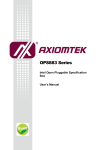
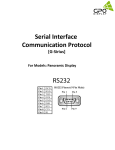
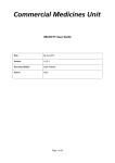
Figure 1-1 illustrates various BIOS layers and components.
STARTUP
BOOT Layer
Functional Layer EEPROM UART
SSCAN
HSS
HPI
SW INT Layer
SW ISR's
HW INT Layer
HW ISR's
HW Interrupt
SPI
HUSB
Services
ISR Groups
ISR Groups
TIMERS
DEBUG
GPIO
EEPROM
UART
IDLE
HSS
UART
SPI
SSCAN
IDE
PUSH/POP
or INT Command
INT Command
HW
Interrupt
Vector
Table
SUSB
HPI
SIE1 - Host
SW
Interrupt
Vector
Table
ALLOC/FREE
REG SWAP
SIE1 - Slave
SUSB
SIE2 - Host
HUSB
SIE2 - Slave
OTG (HNP/SRP)
SIE1 - OTG
SIE1
EP0-EP7
SIE2
EP0-EP7
Figure 1-1. Overview
Chapter 1. BIOS Interface
Page 1-3
BIOS User’s Manual
1.3.1 CY16 Memory Map
The total memory space directly addressable by the CY16 processor is 64 Kbytes. Program, data,
and I/O space are contained within a 64 Kbyte address space. The program code or data can be
stored in internal RAM, external RAM, or external ROM.
The EZ-Host device allows extended data or program code to be stored in external DRAM, SRAM,
or ROM.The total size of extended memory can be up to 2 MByte. The CY16 processor can
access extended memory via two address windows of 0x8000-0x9FFF and 0xA000-0xBFFF. The
page-register 0xc018 is used to control the address window 0x8000-0x9FFF and the page register
0xC01A is used to control the address window of 0xA000-0xBFFF.
The HSS/HPI/SIE1/SIE2/SPI/IDE DMA engines ONLY transfer data between the support hardware to internal RAM (IRAM) and/or internal ROM (IROM). Setting up DMA to external memory
space may result in internal RAM data corruption because the hardware does not check the
address range. For example, setting up a DMA transfer to an external memory address like
0x8000 might result in a DMA transfer into address 0x0000.
The EZ-Host device provides a 16-bit memory interface that can support a wide variety of external
DRAM, RAM, and ROM devices. At boot-up time, the BIOS attempts to detect 8-bit/16-bit external
RAM and external ROM. For external RAM that is mapped to 0x4000-0x7FFF, BIOS attempts to
check the size (8-bit/16-bit) via a write followed by a read verify. If there is SRAM connected to this
BUS, it will allocate this RAM to become part of the BIOS memory space. If there is no SRAM connected to the bus, it will result in an 8-bit setting in the register 0xC03A.
If external ROM is mapped to the address 0xC100, which has a valid signatures scan (i.e. 0xC3B6
or 0xCB36), the BIOS will allow a boot-up from the external ROM code. BIOS can also auto detect
booting up from an 8-bit external ROM or 16-bit external ROM using the special scan signatures at
location 0xC100.
The BIOS will not setup the external memory space. The decision to connect either SRAM or
ROM is left to the user.
The EZ-Host/EZ-OTG memory space is byte addressable. Table 1-1 shows how memory is
divided (1k = 1024 bytes).
Page 1-4
BIOS User’s Manual v1.1
Table 1-1. Memory Map
Function
Address
Memory size
Note
Internal RAM
Hardware Interrupts
Software Interrupts
Primary Register Bank
Swapped Register Bank
HPI Interrupt and Mailbox
LCP CMD Processor Variables
USB Control Registers
Slave Setup Packet
BIOS Stack
USB Slave and OTG Variables
User Code/Data Space (Internal RAM)
0x0000 – 0x3FFF
0x0000 – 0x007F
0x0080 – 0x00FF
0x0100 – 0x010F
0x0120 – 0x013F
0x0140 – 0x0148
0x014A – 0x01FF
0x0200 – 0x02FF
0x0300 – 0x030F
0x0310 – 0x03FF
0x0400 – 0x04A2
0x04A4 – 0x3FFF
16 KBytes
External RAM
0x4000 – 0x7FFF
16 KBytes
3
Extended Page 1
DRAM/SRAM/ROM
0x8000 – 0x9FFF
8 KBytes
1, 2, 3
Extended Page 2
DRAM/SRAM/ROM
0xA000 – 0xBFFF
8 KBytes
1, 2, 3
Memory Mapped Registers
0xC000 – 0xC0FF
256 Bytes
External ROM/External SRAM
0xC100 – 0xDFFF
7,936 Bytes
Internal ROM
0xE000 – 0xFFFF
8K Bytes
3
NOTES:
1.
2.
3.
If code is contained in the Extended Memory Pages, only 32K is usable because the CY16 RISC Core has 16-bit
address generation.
If used for ROM space total ROM space is 16K+7936.
The external memory interfaces are only available on the EZ-Host and not on EZ-OTG
Figure 1-2 illustrates how memory is organized. Each external memory space can be 8- or 16-bits
wide, and can be programmed to have up to seven wait states.On power-up, the BIOS sets all the
default external memory wait state at 7-wait states (i.e. Register 0xC03A will be initialized to
0x27F7).
Note: Each memory wait state results in an extra 20.8ns added to the read/write cycle.
Chapter 1. BIOS Interface
Page 1-5
BIOS User’s Manual
Internal Memory
HW INT's
0x000-- 0x0FF
SW INT's
0x100-- 0x11F
Primary Registers
0x120-- 0x13F
Swap Registers
0x140-- 0x148
HPI Interrupt and
Mailbox
0x14A-- 0x1FF
LCP CMD Processor
Variables
0x200-- 0x2FF
USB Registers
0x300-- 0x30F
Slave Setup Packet
0x310-- 0x3FF
BIOS stack
0x400-- 0x4A2
USB slave and OTG
0x4A4-- 0x3FFF
USER CODE
~15KB
External Memory
0x4000
0x8000
EXT RAM (8K)
8K Extended
Memory Page 1
DRAM/SRAM/ROM
0xA00
0
8K Extended
Memory Page 2
DRAM/SRAM/ROM
0xC000-- 0xC0FF
Control Registers
0xC100
0xE000-- 0xFFFF
EXT ROM
Internal ROM
BIOS (8K)
Figure 1-2. CY16 Memory Map
Note: The external memory interface is only available on the EZ-Host device.
Page 1-6
BIOS User’s Manual v1.1
1.3.2 BIOS Initialization Process
On reset, the BIOS performs the following:
•
Hardware reset — Sets the speed control register to divide by 16 ([0xC008] = 0x000F).
This provides the CY16 processor with a 3 MHz clock. Sets the program counter to
0xFF00.
•
Jumps to 0xE000, the start of BIOS ROM code.
•
Sets call stack pointer (r15) to 0x400.
•
Sets the speed control register to zero ([0xC008] = 0x0) and disables global interrupt.
•
The BIOS then sets the external memory control register for a 16-bit XROM and 16-bit
XRAM five wait states ([0xC03A] = 0x2777).
•
If an external ROM contains the pattern 0xCB36 in location 0xC100, the BIOS immediately
jumps to location 0xC102.
•
The BIOS then tests ROM at location 0xC100 for the pattern 0xC3B6 in 8-bit mode. If the
external ROM shows only the pattern 0xB6, then bit 7 of the external memory control register (0xC03A) is set to one for 8-bit operation. In the EZ-OTG device (i.e., the 48-pin
package) the BIOS sets up from 8-bit ROM mode to GPIO mode, if the BIOS does not
detect any valid scan signatures.
•
Sets 0xC018 = 0 (page0: from 0x8000-0x9FFF) and 0xC01A = 1 (page1: from 0xA0000xBFFF).
•
Tests and enables RAM at location 0x6000 for 8- or 16-bit operation as appropriate.
•
Sets the global interrupt enable register (0xC00E) to zero.
•
Initializes hardware/software interrupt vectors.
•
Initializes arena information (memory management).
•
Initializes hardware for serial EEPROM and UART
•
Initializes software for LCP idle task and USB idle task.
•
Performs BOOT CONTROL (see Section 1.3.3, "Boot Control").
•
Performs SCAN_INT if data at ROM address 0xC100 = 0xC3B6.
•
Enters execution idle tasks and waits for interrupts.
Chapter 1. BIOS Interface
Page 1-7
BIOS User’s Manual
1.3.3 Boot Control
Two pins (GPIO [30:31]) on the EZ-Host and EZ-OTG devices are used for boot control. The boot
control is used to configure the device for Host or peripheral operation and to select a communication port for connection to an external processor.
1.3.3.1 SIE1 Host/Peripheral USB Initialization
GPIO 29 (OTG ID pin) is used to select either Host USB initialization or peripheral USB initialization.
1.3.3.2 Co-processor and Stand-alone Boot Control
EZ-Host and EZ-OTG devices can be used in two basic configurations: stand-alone mode and coprocessor mode. In stand-alone mode the chip is not connected to an external CPU of any kind.
Application specific firmware must be run on the internal processor. One option for loading this
code is to use an external EEPROM, which is selected using the boot control pins.
In co-processor mode the chip is connected to an external master via one of three possible interfaces: Host Processor Interface (HPI), High Speed Serial (HSS), or Serial Peripheral Interface
(SPI). The BIOS uses the boot control pins to determine the default port. This port is used to load
code and data, and is monitored for Link Control Protocol (LCP) commands.
GPIO pins 30 and 31 are used as the boot control pins. The possible configurations are described
below:
Table 1-2. Boot Control Pins
GPIO 30
GPIO 31
Mode
Boot Port and Baud
0
0
co-processor
HPI
0
1
co-processor
HSS GPIO mode, Baud = 115.2K
1
0
co-processor
SPI GPIO mode
1
1
stand-alone
EEPROM
Note:
* In co-processor mode all USB ports are disabled at power-up and must be turned on the
external processor using LCP commands. For example, in peripheral mode the chip will not
respond to any USB commands from the host until the ports have been enabled.
* In stand-alone mode, the USB-PortC always goes into full speed peripheral mode, which is
dedicated for the debugger usage. The USB-PortA goes into peripheral mode if GPIO29 is
high, and goes into host mode when GPIO29 is low.
* In stand-alone mode, users can use the serial EEPROM to over-ride the default mode for
both USB-PortA and USB-PortC. In this mode, BIOS will use SCAN_INT so user applications can be loaded into RAM from the EEPROM.
Page 1-8
BIOS User’s Manual v1.1
1.4
Link Control Protocol (LCP)
The link control protocol allows an external processor to have full access and control over the EZHost/EZ-OTG devices. The boot control determines which interface (HPI/HSS/SPI) will be enabled
for receiving LCP commands on power-up. The LCP commands are common for all interfaces but
the communication protocol varies slightly between them due to capability differences of the interfaces. This section describes the methods used to access the EZ-Host/EZ-OTG devices via each
of the three interfaces.
The BIOS does not support queuing of LCP commands. Only one LCP command may be executed at one time.
The following table shows which LCP commands are available and useful for each port.
Table 1-3. Commands Used for each Transport
LCP Command
HPI
Transport
HSS
Transport
SPI
Transport
COMM_RESET
Yes
Yes
Yes
COMM_JUMP2CODE
Yes
Yes
Yes
COMM_CALL_CODE
Yes
Yes
Yes
COMM_EXEC_INT
Yes
Yes
Yes
COMM_READ_CTRL_REG
Yes
Yes
Yes
COMM_WRITE_CTRL_REG
Yes
Yes
Yes
COMM_READ_MEM
Yes*
Yes
Yes
COMM_WRITE_MEM
Yes*
Yes
Yes
COMM_READ_XMEM
Yes
Yes
Yes
COMM_WRITE_XMEM
Yes
Yes
Yes
COMM_CONFIG
Yes*
Yes
Yes*
Note: *BIOS returns COMM_ACK ONLY.
1.4.1 LCP Overview for Host Processor Interface (HPI)
Refer to Chapter 5, "HPI Transport Module" for a complete discussion on this topic.
HPI is a dual channel interface. By default, the BIOS uses the HPI direct memory access for memory read/write of data, and the mailbox for LCP commands and responses.
LCP commands are always sent in a 16-bit word, and a 16-bit response is expected. A sequence
diagram of each LCP command is given in Chapter 5.
Note: Unless specifically mentioned, all responses are either COMM_ACK or COMM_NAK.
Chapter 1. BIOS Interface
Page 1-9
BIOS User’s Manual
1.4.1.1 Programming Overview
HPI functionality is such that the following operations should happen for each LCP Command that
is issued:
•
Any data required for the LCP CMD is sent via HPI DMA (i.e., COMM_CODE_ADDR).
•
The LCP command is then sent via HPI mailbox.
•
The HPI status register is polled (or an ISR is used) to wait for mailbox response back
from the BIOS.
•
The response is then read from the mailbox.
•
Any additional data from CMD execution is read using HPI DMA (i.e.,
COMM_CTRL_REG_DATA).
1.4.2 LCP Overview for High Speed Serial (HSS)
Refer to Chapter 7, "HSS Transport Module" for complete details on this topic.
HSS is a full-duplex interface. By default, the BIOS sets up the HSS port as a simple 2-wire interface with no hardware or software handshaking.
LCP commands are always sent in an 8-byte packet. This packet contains the 16-bit LCP command and in some cases additional data for the command (like address and length of data to follow). When the Host sends down a command, the Host must be ready to receive the resultant data
via an ISR.
A sequence diagram of each LCP command is given in Chapter 7.
Note: The external host processor is in full control of the interface as a master. The Host must give
time to the BIOS in between sending LCP commands. The Host should wait at least 30 microseconds between sending a new command packet. While changing BAUD rate commands via the
COMM_CONFIG, the Host must wait at least 100 microseconds before sending any new commands with the new baud rate.
Page 1-10
BIOS User’s Manual v1.1
bool hss_xfer(char *cmd; int len; char *buf)
{
int i, stat;
bool data_wr=FALSE;
if (len>2048) return FALSE; // (*) hss HW support upto 1024-words
for (i=0; i<8; i++)
HSS_Write_byte(cmd[i]); // (8-byte commands) no delay here
// Read_ACK/NAK status:
stat=HSS_Read_byte();
stat = (HSS_Read_byte() << 8) + stat;
i = (cmd[0] + (cmd[1]<<8));
switch (i)
{
case COMM_WRITE_XMEM:
case COMM_WRITE_MEM: data_wr = TRUE;
}
if (len > 0)
{
if (data_wr) for (i=0; i<len; i++) HSS_Write_byte(buf[i]);
else for (i=0; i<len; i++) buf[i] = HSS_Read_byte();
}
if (i==COMM_CONFIG) Delay_100us()
// requires for change baud rate
else Delay_30us();
// between LCP need this delay
return TRUE;
}
* The HSS hardware transfer length only supports up to 2048 bytes, i.e., 1024 words.
Chapter 1. BIOS Interface
Page 1-11
BIOS User’s Manual
1.4.3 LCP Overview for Serial Peripheral Interface (SPI)
Refer to Chapter 6, "SPI Transport Module Firmware" for complete details on this topic.
In SPI mode the EZ-Host or EZ-OTG device acts as an SPI Slave to the external host. The SPI
connection requires a more detailed protocol because it is a master driver, synchronous, halfduplex interface. Hence the master must poll for the data after an LCP command is issued or it
must use an additional hardware interrupt to notify the Host that data is ready. The BIOS supports
both modes of communication. In the SPI mode, the GPIO24 line can be used as the interrupt line
to the external processor, if the application avoids polling the COMM_ACK status.
Note: The external host processor is in full control of the interface as a master. The Host must give
time to the BIOS in between sending LCP commands and reading responses. The Host should
wait at least 100 microseconds after sending a CMD packet before attempting to poll the
response. Also, after receiving a response the host should wait 100 microseconds before issuing
another CMD packet. For example:
bool spi_xfer(char *cmd; int len; char *buf)
{
int i, stat;
bool data_wr=FALSE;
if (len>1024) return FALSE; // (*) spi HW support upto 512-words
for (i=0; i<8; i++)
SPI_Write_byte(cmd[i]); // (8-byte commands) no delay here
// Read_ACK/NAK status:
do
{
Delay_100us();
stat=SPI_Read_byte();
} while (stat == 0xff);
stat = (SPI_Read_byte() << 8) + stat;
i = (cmd[0] + (cmd[1]<<8));
switch (i)
{
case COMM_WRITE_XMEM:
case COMM_WRITE_MEM: data_wr = TRUE;
}
if (len > 0)
{
if (data_wr) for (i=0; i<len; i++) SPI_Write_byte(buf[i]);
else for (i=0; i<len; i++) buf[i] = SPI_Read_byte();
}
Delay_100us(); // between LCP need this delay
return TRUE;
}
* The SPI hardware transfer length only support up to 1024-byte i.e. 512 word.
Page 1-12
BIOS User’s Manual v1.1
1.5
Hardware Interrupts
There are 48 hardware interrupt vectors for the EZ-Host/EZ-OTG devices. The only real difference
between a hardware interrupt and a software interrupt is the fact that a hardware interrupt is triggered by an event in hardware. This may seem obvious, but it is important to understand that hardware interrupts can be called with the INT instruction the same way as software interrupts are, and
any reserved or free hardware interrupts can be used as a software interrupt since there is no
hardware stimulus associated with it. The EZ-Host/EZ-OTG hardware interrupt vectors are listed in
Table 1-4.
Table 1-4. Hardware Interrupt Table
Interrupt
Number
Vector
Address
0
0x00
Timer0 (free for developer)
2
1
0x02
Timer1 (free for developer)
2
2
0x04
GP IRQ0 (free for developer)
2
3
0x06
GP IRQ1 (free for developer)
2
4
0x08
UART Tx (reserved for debugger)
1
Interrupt Type
Note
5
0x0A
UART Rx (reserved for debugger)
1
6
0x0C
HSS DMA Done (reserved for LCP)
1
7
0x0E
HSS Rx Full (reserved for LCP)
1
8
0x10
IDE DMA Done (free for developer)
3
9
0x12
Reserved for future hardware
4
10
0x14
HPI Mailbox RX Empty (reserved for LCP)
1
11
0x16
HPI Mailbox TX Full (reserved for LCP)
1
12
0x18
SPI Tx (reserved for LCP)
1
13
0x1A
SPI Rx (reserved for LCP)
1
14
0x1C
SPI DMA Done (reserved for LCP)
1
15
0x1E
OTG ID / VBUS Valid (free for developer)
3
16
0x20
SIE1 Host Done (reserved for BIOS)
1
17
0x22
SIE1 Host SOF (reserved for BIOS)
1
18
0x24
SIE1 Host Ins/Remove (free for developer)
3
19
0x26
Reserved for future hardware
4
20
0x28
SIE1 Peripheral Reset (reserved for BIOS)
1
21
0x2A
SIE1 Peripheral SOF (reserved for BIOS)
1
22
0x2C
Reserved for future hardware
4
23
0x2E
Reserved for future hardware
4
24
0x30
SIE2 Host Done (reserved for BIOS)
1
25
0x32
SIE2 Host SOF (reserved for BIOS)
1
Chapter 1. BIOS Interface
Page 1-13
BIOS User’s Manual
Table 1-4. Hardware Interrupt Table (Continued)
Interrupt
Number
Vector
Address
26
0x34
SIE2 Host Ins/Remove (free for developer)
3
27
0x36
Reserved for future hardware
4
28
0x38
SIE2 Peripheral Reset (reserved for BIOS)
1
29
0x3A
SIE2 Peripheral SOF (reserved for BIOS)
1
30
0x3C
Reserved for future hardware
4
31
0x3E
Reserved for future hardware
4
32
0x40
SIE1 Endpoint 0 Interrupt (reserved for BIOS)
1
33
0x42
SIE1 Endpoint 1 Interrupt (reserved for BIOS)
1
34
0x44
SIE1 Endpoint 2 Interrupt (reserved for BIOS)
1
35
0x46
SIE1 Endpoint 3 Interrupt (reserved for BIOS)
1
36
0x48
SIE1 Endpoint 4 Interrupt (reserved for BIOS)
1
37
0x4A
SIE1 Endpoint 5 Interrupt (reserved for BIOS)
1
38
0x4C
SIE1 Endpoint 6 Interrupt (reserved for BIOS)
1
39
0x4E
SIE1 Endpoint 7 Interrupt (reserved for BIOS)
1
40
0x50
SIE2 Endpoint 0 Interrupt (reserved for BIOS)
1
41
0x52
SIE2 Endpoint 1 Interrupt (reserved for BIOS)
1
42
0x54
SIE2 Endpoint 2 Interrupt (reserved for BIOS)
1
43
0x56
SIE2 Endpoint 3 Interrupt (reserved for BIOS)
1
44
0x58
SIE2 Endpoint 4 Interrupt (reserved for BIOS)
1
45
0x5A
SIE2 Endpoint 5 Interrupt (reserved for BIOS)
1
46
0x5C
SIE2 Endpoint 6 Interrupt (reserved for BIOS)
1
47
0x5E
SIE2 Endpoint 7 Interrupt (reserved for BIOS)
1
Interrupt Type
Note
NOTES:
1.
2.
3.
4.
These hardware interrupt vectors are reserved for internal BIOS usage. Users should not attempt to overwrite these
functions.
These hardware interrupt vectors are not initialized.
These hardware interrupt vectors are initialized with empty ISR subroutine
These hardware interrupt vectors are reserved for future hardware expansion. Users should not use these vectors
All these vector interrupts are read/write accessible. Users can overwrite these default interrupt
vectors by replacing their interrupt service subroutine. Example 1, “Modify Timer 1 Interrupt Vector” demonstrates how you can replace the hardware interrupt.
Example 1: Modify Timer 1 Interrupt Vector.
Initialize:
mov
or
…
ret
Page 1-14
[0x0002],Timer1_isr
[0xc00e],2
; New Timer1 ISR
; enable timer1 interrupt
BIOS User’s Manual v1.1
Timer1_isr:
push [0xc000]
mov [0xc012],30000
…
pop [0xc000]
sti
ret
; push the flags register
; reload timer 1
; Restore flags
; enable interrupts
; return
1.5.1 BIOS Hardware Interrupt Usage
Most hardware interrupts are used by the BIOS. The user can override these ISRs but care must
be taken.
1.5.1.1 Interrupts Not Used by the BIOS
The following interrupts are not used by the BIOS and can be utilized by the developer.
Table 1-5. Interrupts not used by the BIOS
Interrupt
Number
Interrupt Name
0
Timer0
1
Timer1
2-3
Notes
GPIO IRQ0 and GPIO IRQ1
8
IDE DMA Done
15
OTG ID / VBUS Valid
18
SIE1 Host Insert/Remove
26
SIE2 Host Insert/Remove
1
NOTE: Interrupt 15 is available to implement USB On-The-Go support
Chapter 1. BIOS Interface
Page 1-15
BIOS User’s Manual
1.5.1.2 Interrupts Used by the BIOS
The following interrupts are used by the BIOS.
Table 1-6. Hardware Interrupt Table
Interrupt
Number
Interrupt Name
Notes
4
UART Tx
ISR: transmits characters from the software 16-byte FIFO
Note: Overriding effects tool support over UART
5
UART Rx
ISR: receives characters and store into the software 16byte FIFO.
Note: Overriding effects tool support over UART
6
HSS DMA Done
ISR: Used by HSS Transport to support LCP
7
HSS Rx Full
ISR: Used by HSS Transport to support LCP
9
Reserved
Reserved for future HW
10
HPI Mailbox TX Empty
ISR: Used by HPI Transport to support LCP
11
HPI Mailbox RX Full
Not used: Reserved for BIOS
12
SPI Tx
Not used: Reserved for BIOS
13
SPI Rx
ISR: Used by SPI Transport to support LCP
14
SPI DMA Done
ISR: Used by SPI Transport to support LCP
16
SIE1 Host Done
ISR: services a single packet via the Transfer Descriptor
(TD). It will post the message to the HPI mailbox register
0x144 with 0x1000 after all the TD list items are serviced.
17
SIE1 Host SOF
ISR: services the TD list that supply from the application.
As soon as the TD is not empty, it will start TD transaction.
20
SIE1 Peripheral Reset
ISR: enter this ISR after 5us of the falling edge of the
USB_RESET. This interrupt will call the SUSB1_INIT_INT
and will post the message to the HPI mailbox register
0x144 with value 0x100
21
SIE1 Peripheral SOF
ISR: services for every 1ms SOF detect from USB Host.
After second SOF detection, it will send a message to HPI
mailbox register 0x144 with value 0x200. After detecting
seven consecutive missing SOFs, it will set the value
0x800 to the HPI mailbox register 0x144
24
SIE2 Host Done
ISR: services a single packet via the Transfer Descriptor
(TD). It will post the message to the HPI mailbox register
0x148 with 0x1000 after all the TD list items are serviced.
25
SIE2 Host SOF
ISR: services the TD list that supply from the application.
As soon as the TD is not empty, it will start TD transaction.
Page 1-16
BIOS User’s Manual v1.1
Table 1-6. Hardware Interrupt Table (Continued)
Interrupt
Number
Interrupt Name
Notes
28
SIE2 Peripheral Reset
ISR: enter this ISR after 5us of the falling edge of the
USB_RESET. This interrupt will call the SUSB2_INIT_INT
and will post the message to the HPI mailbox register
0x148 with value 0x100
29
SIE2 Peripheral SOF
ISR: services for every 1ms SOF detect from USB Host.
After second SOF detection, it will send a message to HPI
mailbox register 0x148 with value 0x200. After detecting
seven consecutive missing SOFs, it will set the value
0x800 to the HPI mailbox register 0x148
32
SIE1 Endpoint0
ISR: services USB full/low speed enumeration in portA,
which defined by the SUSB_INIT_INT. It handles retry
when detect any ERROR in the USB bus. It also supports
RedHat debugger/QTOOL and services the
SUSB1_SEND_INT + SUSB1_RECEIVE_INT. It will set
the bit0 of the HPI mailbox register 0x144 for every
SUSB1_SEND_INT.
SIE1 Endpoint 1-7 Interrupt
ISR: This interrupt supports the SUSB1_SEND_INT and
SUSB1_RECEIVE_INT. It handles retry when it detects an
ERROR in the USB BUS. After the transfer of data that
defines this interface is complete, it will set bits 1-7 in the
HPI mailbox register 0x144.
SIE2 Endpoint0
ISR: services USB full/low speed enumeration in portA,
which defined by the SUSB_INIT_INT. It handles retry
when detect any ERROR in the USB bus. It also supports
the Red Hat debugger and services the
SUSB2_SEND_INT + SUSB2_RECEIVE_INT. It will set
the bit0 of the HPI mailbox register 0x148 for every
SUSB2_SEND_INT.
SIE2 Endpoint 1-7 Interrupt
ISR: This interrupt supports the SUSB2_SEND_INT and
SUSB2_RECEIVE_INT. It handles retry when detect
ERROR in the USB BUS. After the transfer of data that
defines this interface is complete, it will set bits 1-7 in the
HPI mailbox register 0x148.
32-39
40
41-47
Chapter 1. BIOS Interface
Page 1-17
BIOS User’s Manual
1.6
Debugging Tools support
The BIOS supports the debugger via the following interfaces:
UART: Default baud rate = 28800, 8-bit, no-parity, 1 stop-bit, flow control: none
The UART port will be used by the debugger
USB-portC will be used by the debugger.
HPI/HSS/SPI via LCP. The debugger software does not support debugging over these
interfaces. Users will make use of these interfaces for their application development.
Note: USB-portA can also be used for the debugger, when it is configured as the peripheral. In coprocessor mode, both USB-portA and USB-portC will not be available to the debugger. Only the
UART will be available in the EZ-Host chip because of design requirements.
Note: In co-processor mode, the debugger on the USB ports can be enabled by calling the
SUSB_INIT_INT via the LCP interface in both EZ-Host and EZ-OTG devices.
Note: The UART and USB debugging ports are not available when the EZ-OTG chip is setup in
the HPI mode (co-processor mode) because HPI pins are shared with the UART pins. However,
the UART will be available when the EZ-OTG chip is setup in either HSS or SPI mode.
Note: The UART debugging port is available when the EZ-Host chip is setup in the HPI/HSS/SPI
mode.
Page 1-18
BIOS User’s Manual v1.1
1.7
Software Interrupts
The EZ-Host and EZ-OTG allocate address locations from 0x0060 to 0x00FE to software interrupts. The software interrupt vectors are listed in Table 1-7.
Table 1-7. Software Interrupt Table
Interrupt
Number
Vector
Address
48
0x60
Reserved for LCP status message
1
49
0x62
Reserved for LCP asynchronous message
1
50
0x64
Reserved for future BIOS on OTG Variable Data: Default =
0 = OTG State
2
51-63
0x66-0x7F
64
0x80
Two-wire serial EEPROM (from 256-byte to 2K-byte)
1
65
0x82
Two-wire serial EEPROM from (4k-byte to 16k byte)
1
Interrupt Type
Free for developers
Notes
3,4
66
0x84
UART_INT
1
67
0x86
SCAN_INT
1
68
0x88
ALLOC_INT
1
69
0x8A
Variable Data Pointer: start of free memory
2
70
0x8C
IDLE_INT
1
71
0x8E
IDLER_INT
1
72
0x90
INSERT_IDLE_INT
1
73
0x92
PUSHALL_INT
1
74
0x94
POPALL_INT
1
75
0x96
FREE_INT
1
76
0x98
REDO_ARENA
1
77
0x9A
HW_SWAP_REG
1
78
0x9C
HW_REST_REG
1
79
0x9E
SCAN_DECODE_INT
1
80
0xA0
SUSB1_SEND_INT
1
81
0xA2
SUSB1_RECEIVE_INT
1
82
0xA4
SUSB1_STALL_INT
1
83
0xA6
SUSB1_STANDARD_INT
1
84
0xA8
OTG_SRP_INT
1
85
0xAA
SUSB1_VENDOR_INT (default=SUSB1_STALL_INT)
4
86
0xAC
REMOTE_WAKEUP_INT
1
87
0xAE
SUSB1_CLASS_INT (default=SUSB1_STALL_INT)
4
88
0xB0
Variable Data pointer: OTG descriptor
4
89
0xB2
SUSB1_FINISH_INT
1
Chapter 1. BIOS Interface
Page 1-19
BIOS User’s Manual
Table 1-7. Software Interrupt Table (Continued)
Interrupt
Number
Vector
Address
90
Interrupt Type
Notes
0xB4
Variable Data pointer: SUSB1 Device Descriptor. Default =
Cypress Device Descriptor
2,4
91
0xB6
Variable Data pointer: SUSB1Configuration Descriptor.
Default = Cypress Configuration Descriptor
2,4
92
0xB8
Variable Data pointer: SUSB1 String Descriptor. Default =
Cypress String Descriptor
2,4
93
0xBA
Reserved for future BIOS
1
94
0xBC
SUSB1_LOADER_INT
1
95
0xBE
SUSB1_DELTA_CONFIG_INT
1
96
0xC0
SUSB2_SEND_INT
1
97
0xC2
SUSB2_RECEIVE_INT
1
98
0xC4
SUSB2_STALL_INT
1
99
0xC6
SUSB2_STANDARD_INT
1
100
0xC8
Reserved for future BIOS
1
101
0xCA
SUSB2_VENDOR_INT (default: SUSB2_STALL_INT)
4
102
0xCC
Reserved for future BIOS
1
103
0xCE
SUSB2_CLASS_INT (default: SUSB2_STALL_INT)
4
104
0xD0
Reserved for future BIOS
1
105
0xD2
SUSB2_FINISH_INT
106
0xD4
Variable Data pointer: SUSB2 Device Descriptor. Default =
Cypress Device Descriptor
2,4
107
0xD6
Variable Data pointer: SUSB2Configuration Descriptor.
Default = Cypress Configuration
2,4
108
0xD8
Variable Data pointer:SUSB2 String Descriptor. Default =
Cypress String Descriptor
2,4
109
0xDA
Reserved for future BIOS
110
0xDE
SUSB2_LOADER_INT
1
111
0xE0
SUSB2_DELTA_CONFIG_INT
1
112
0xE2
Reserved for future BIOS on OTG_STATE_INT
1
113
0xE4
SUSB_INIT_NT
1
114
0xE6
HUSB_SIE1_INIT_INT
1
115
0xE8
HUSB_SIE2_INIT_INT
1
116
0xEA
HUSB_RESET
1
KBHIT_INT
117
0xEC
118- 125
0xEE-0xFA
Free for developers
126- 127
0xFC-0xFF
Reserved for debugger
1
1
1
3,4
3
NOTES:
1.
2.
3.
4.
Page 1-20
These software vectors are used by the internal BIOS.
These vectors are used as the data pointers. Users should not execute code (i.e. JMP or INT) to these vectors.
These interrupt vectors are not initialized.
These interrupt vectors are free for developers
BIOS User’s Manual v1.1
1.7.1 Interrupt 48-49: LCP Message Subroutines
The BIOS uses these two interrupts for the lcp_idle task, so users should not modify these interrupts. Note: LCP only supports the HPI/HSS/SPI hardware interfaces and is designed to work in
co-processor mode.
1.7.2 Signature SCAN Support
The signature scan support is a comprehensive control protocol that allows UART, serial EEPROM
(I2C), USB, and external ROM to interface to the BIOS. The design of this interface provides users
a consistent method to expand the capabilities of the BIOS, over-ride BIOS functions and support
a debugger interface.
At power-up, the BIOS will do a signature SCAN for the I2C (stand-alone mode) and external
ROM. After power-up, the BIOS will create two idle tasks, which are UART tasks and USB tasks
for monitoring the signature SCAN in real-time. Note: Both these tasks run concurrently, so both
debuggers can be executed at a same time. The BIOS reserves a background task for the UART/
USB via the uart_idle and usb_idle tasks. These background tasks call the SCAN interrupt for the
special signature word 0xC3B6 (not 0xCB36) from the UART/USB. All chip-access utilities and
debuggers use this command protocol.
The following functions are supported and subsequently described:
•
SCAN_INT
•
SCAN_DECODE_INT
1.7.2.1 Interrupt 67: SCAN_INT
The SCAN interrupt is used in conjunction with other software interrupts to allow loading and executing of user code and data. During boot-up the BIOS scans the external ROM and serial
EEPROM (I2C) for a valid Scan Signature of 0xC3B6. If found, the Signature Scan Opcodes and
data are processed, allowing code and data to be moved into the CY16’s RAM space and executed. As mentioned earlier, the debugging utilities use this system for low-level communication to
the EZ-Host or EZ-OTG devices. During run-time, BIOS will use the uart_idle and usb_idle background tasks to continuously scan the signature. So, these tasks need to be maintained (see the
STUB source code) and this requires correct use of the IDLE_INT.
Note: Interrupts will not be enabled until these scans have been completed.
During the BIOS boot-up, a special external ROM signature of 0xCB36 will cause the BIOS to jump
into the location following the signature for the entire BIOS override.
Chapter 1. BIOS Interface
Page 1-21
BIOS User’s Manual
1.7.2.1.1
Software Interface
Entry:
R7: Contains the address of a subroutine that is called by this interrupt when the next byte is
required. This routine must:
•
Return the byte in the lower half of R0 with the upper half cleared
•
Leave R1, R2, R8, and R9 intact
Registers Usage: None.
Signature Data Structure Format:
dw 0xc3b6
Starting Signature
dw Length
Length of data to follow, exclusive of signature, length, and opcode
db OpCode
Type of action to take
db Data[]
1 to n bytes of data, depending on OpCode and length
Format of Data for each OpCode:
OpCode = 0x00: Write Data
dw Starting Address
db Data0..DataN
OpCode = 0x01: Write At Interrupt Vector
db Interrupt Vector Number
db Data0..DataN
OpCode = 0x02: Write Interrupt Service Routine
db Interrupt Vector Number
db Data0..DataN (see Note 1 below)
OpCode = 0x03: Fix-up (relocate) ISR Code
db Interrupt Vector Number
dw Offset0..OffsetN (see Note 2 below)
OpCode = 0x04: Jump to Absolute Address
dw Address
OpCode = 0x05: Call Absolute Address
dw Address
OpCode = 0x06: Call Interrupt
db Interrupt Number
Page 1-22
BIOS User’s Manual v1.1
OpCode = 0x07: Read Memory using Interrupt
db Interrupt Number
dw Interface Address (if interface needs an address)
dw Address of data to write
dw Length of data to write
OpCode = 0x08: Move Data using Interrupt
db Interrupt Number
dw initial address to write
db Data0..DataN to write using Interrupt
OpCode = 0x09: Write Configuration
db configuration address to write (a 0xc000 is added for the device address)
dw data to write to above address
db next configuration address
dw next data to write
dw 0xc3b6 if more data to follow
or dw 0000 if no more data
Note 1: If data is code, the code must be re-locatable, i.e., no calls or long jumps within the
code unless a fix-up is done (see Note 2).
Note 2: A fix-up is an offset to code that is assembled assuming a start point of zero. This offset should then have the real starting location added to it.
1.7.2.1.2
Example
BIOS Sample code for copying code and data from external ROM to external RAM starting at
address 0xC100.
;*****************************************************************
; scan external ROM
;*****************************************************************
scan_xrom:
mov r10,0xc100
;XROM_BEGIN
mov r7,get_next_byte
;get next byte from external ROM
int SCAN_INT
ret
get_next_byte:
mov r0,b[r10++]
ret
In this example, the user creates a file called “sample1.asm”, which has the following header in the
external ROM that mapped to address 0xC100.
Chapter 1. BIOS Interface
Page 1-23
BIOS User’s Manual
Example 2: Download code/data from external ROM to internal RAM at 0x500 and jump
to execute this code after finish downloading.
org 0xc100
IRAM equ 0x500
dw
dw
db
dw
dw
0xC3B6
4
0
0xc008
0
;destination execute address inside IRAM
;dummy signature for code alignment
;mov [0xc008],0
;address = 0xc008
;data = 0
dw 0xC3B6
;
dw (END-START)+2) ;Include the length+1byte alignment
db 0
;Type 0x00 = Copy from external ROM to external RAM
dw IRAM
;Copy to external RAM starts at 0x500
reloc IRAM
;Relocate compiled symbols
START:
;User code. Beginning of program starts here
;Code and Data
…
END:
;The following sequence instructs the BIOS to execute
;the copied program.
Signature1:
dw
0xC3B6
dw
2
;Length = 2
db
5
;Type 0x05 = call the following location
dw
IRAM
;Jump to IRAM code start
db
0
;Stop Scan word
1.7.2.2 Interrupt 79: SCAN_DECODE_INT
Interrupt 67 calls interrupt 79 for function table decoding of the interrupt 67 calls. Interrupt 79 is
reserved for BIOS use.
1.7.2.2.1
Software Interface
Entry:
R7 pointer to get_next_byte subroutine
Registers Usage: R0, R8, R9
Return:
R0 = 0
Page 1-24
BIOS User’s Manual v1.1
Example: BIOS Listing of the SCAN_INT that call the SCAN_DECODE_INT
scan:
call scan_get_word
cmp r0,0xc3b6
jne scan_exit
call scan_get_word
mov r2,r0
call r7
int SCAN_DECODE_INT
jmp scan
scan_exit:
xor r0,r0
ret
; length
; opcode
;*****************************************************************
; return r0 word data
;*****************************************************************
scan_get_word:
call r7
; Uses Routine pointed by R7 to Read byte
push r0
call r7
shl r0,8
; upper byte
or
r0,[r15]
; r0 = r0 or pop(r0)
ret
1.7.3 OTG Interrupt Functions
The following functions are dedicated for the OTG design and subsequently described:
•
OTG_STATE
•
OTG_STATE_INT
•
OTG Descriptor
•
OTG_SRP_INT
•
REMOTE_WAKEUP_INT
Note: These functions are not implemented in the current release of the BIOS and these interrupts
and variables are reserved for future BIOS.
Chapter 1. BIOS Interface
Page 1-25
BIOS User’s Manual
1.7.3.1 Interrupt 50 (OTG_STATE)
The BIOS uses this location as the variable for the OTG state machine i.e., b_idle and a_idle state
machines from the On-The-Go (OTG) supplement to the USB 2.0 Specification. This variable will
be updated when users call the OTG_STATE_INT. The defined state will be shown as follows:
a_idle
a_wait_bcon
a_host
a_suspend
a_peripheral
a_wait_vfall
b_idle
b_peripheral
b_host
equ
equ
equ
equ
equ
equ
equ
equ
equ
0
1
2
3
4
5
6
7
8
Note: This variable is used by the BIOS. Users should not write to this location.
1.7.3.2 Interrupt 112 (OTG_STATE_INT)
The BIOS supports both a_idle and b_idle state machines for USB-portA only. This interrupt provides support for Session Request Protocol (SRP) and Host Negotiation Protocol (HNP). The
BIOS controls and monitors all the low-level interface i.e. VBUS, OTG_ID, D+/D- pull-up/down,
VBUS pump charge, VBUS pull-up, VBUS-discharge and user’s request (i.e. a_bus_drop,
a_bus_req, b_bus_req etc.). The results of this interrupt will return the state transition from the
current to the next state that follow the OTG supplement to the USB 2.0 specification.
1.7.3.2.1
Software Interface
Entry:
R0 [15:0] bits are defined as follow:
a_bus_drop
a_set_b_hnp_en
bus_req
a_suspend_req
equ
equ
equ
equ
0x0001
0x0002
0x0004
0x0008
b_do_srp
b_hnp_en
b_speed
equ 0x0010
equ 0x0040
equ 0x0080
;from
;from
;from
;from
application:
application:
application:
application:
A-device request bus drop
enable hnp
for both a_bus_req & b_bus_req
A-device request bus suspend
;from app: must call otg_srp then set this variable
;from app: Slave needs to detect the SET_FEATURE
;from app: 0=full, 1=low
Registers Usage: None.
Return:
R0 = OTG_STATE (location at address 50*2 = 0x0064)
R0 = return one of the value define as shown below:
Page 1-26
BIOS User’s Manual v1.1
a_idle
a_wait_bcon
a_host
a_suspend
a_peripheral
a_wait_vfall
b_idle
b_peripheral
b_host
equ
equ
equ
equ
equ
equ
equ
equ
equ
0
1
2
3
4
5
6
7
8
Note: BIOS handles these following states for a_idle state machine:
a_idle -> a_wait_vrise->a_wait_bcon: a_wait_vrise is handled by the BIOS
Any state transition to a_vbus_err will go to a_wait_vfall.
b_idle -> b_srp_init: when bus_req and b_do_srp are true, BIOS will do the b_srp_init and
return back to b_idle.
If the state is in b_peripheral, BIOS will handle the b_wait_acon state and the result will be
either in the b_host or the b_peripheral state.
For a complete understanding on how the a_idle and b_idle state machines work, refer to the OTG
supplement to the USB 2.0 specification for more details.
1.7.3.3 Interrupt 88 (OTG Descriptor)
The BIOS uses this interrupt as the variable data pointer for the OTG descriptor. At power-up the
BIOS sets this location to zero, i.e., BIOS will send STALL for SET_FEATURE command of
requesting SRP/HNP. When this location contains the OTG descriptor, the BIOS returns an ACK
on the SET_FEATURE of SRP/HNP command. In co-processor mode, this location should be set
before making a call to the SUSB_INIT_INT. In stand-alone mode, it must be overridden by either
serial EEPROM or external ROM if users wish to enable the OTG feature.
Example of the OTG descriptor:
otg_desc:
db 3
db 9
db 3
; len=3
; type = OTG
; HNP|SRP supported
To over-ride the otg_desc do:
mov
[(88*2)],otg_desc
Note: The OTG descriptor should be part of the configuartion_descriptor.
Chapter 1. BIOS Interface
Page 1-27
BIOS User’s Manual
1.7.3.4 Interrupt 84 (OTG_SRP_INT)
This interrupt will do the SRP. The BIOS will pulse the data bus (either D+ or D- depending on the
user’s speed) and VBUS. Before calling this function, both VBUS and D+/D- should be turned off.
If the OTG_ID pin changes from high to low during the pulsing of VBUS and/or D+/D-, the function
will exit and return R0=0. BIOS will try to pull down both Data+ and Data- and it will check if either
Data+ or Data- is still high, it will return R0 with non-zero value to indicate the ERROR.
1.7.3.4.1
Software Interface
Entry:
R0 = VBUS pulse time in milliseconds (must be greater than zero and not more than 30 ms).
R1 = 0 = full speed, 1=low speed.
Registers Usage: None.
Return:
R0 = 0 = Success, else ERROR.
VBUS and D+/D- will turn off.
1.7.3.5 Interrupt 86 (REMOTE_WAKEUP_INT)
This interrupt can be used to do the remote wake-up. When calling this interrupt, it will force the KState for 10 milliseconds in the USB bus.
1.7.3.5.1
Software Interface
Entry:
R0 = sie_num (0 = SIE1, else = SIE2)
Registers Usage: None.
Return:
R0 = 0 = Success, else ERROR.
1.7.4 USB Host Interrupt Functions
The following functions are dedicated for the USB Host design:
•
HUSB_SIE1_INIT_INT/ HUSB_SIE2_INIT_INT
•
HUSB_RESET_INT
Page 1-28
BIOS User’s Manual v1.1
1.7.4.1 Interrupt 114/115: HUSB_SIE1_INIT_INT/ HUSB_SIE2_INIT_INT
HUSB_SIEx_INIT_INT is used to execute the TD list. Refer to Chapter 3 for a detailed discussion
on these interrupts. In co-processor mode, these interrupts must be called via the LCP commands.
In stand-alone mode, the BIOS will call the HUSB_SIE1_INIT_INT if the OTG_ID (GPIO29) pin is
low. The BIOS will set the SIE2 as the full speed peripheral.
1.7.4.1.1
Software Interface
Entry: None.
Registers Usage: None.
Return: None.
1.7.4.1.2
Example:
Set SIE1 as Host and be ready to execute the TD list.
int
ret
HUSB_SIE1_INIT_INT
;Set SIE1 as Host
1.7.4.2 Interrupt 116: HUSB_RESET_INT
HUSB_RESET_INT has three functions:
USB Reset:
Before accessing a USB device, the HUSB_RESET_INT generates a
USB reset and sends it to USB bus.This forces the peripheral device to its
default address of zero. The minimum time required to hold the USB bus
in USB reset is >=10milliseconds.
After detecting a USB reset, every device responds to USB address zero.
After a USB reset, configuration software can read every device’s
descriptor at the same default address, one device at a time.
Speed Detect:
The HUSB_RESET_INT detects the full/low speed of the attached device
then returns the port status: FULL SPEED, LOW SPEED or NO DEVICE.
SOF/EOP Generation: Based on the device speed, HUSB_RESET_INT generates an SOF for
full speed and an EOP for low speed. If no device is attached on this port,
there will be no SOF/EOP.
Chapter 1. BIOS Interface
Page 1-29
BIOS User’s Manual
1.7.4.2.1
Software Interface
Entry:
R1: Port number:
0=USB-Port0
1=USB-Port1
2=USB-Port2
3=USB-Port3
R0: Time interval for USB reset in milliseconds.
Registers Usage: None.
Return:
This interrupt will return the speed on that port.
R0:
Bit0 = 0
Bit0 = 1
Bit1 = 1
Bit1 = 0
1.7.4.2.2
Full speed
Slow speed
No device
Device is connected
Example
Reset port A, generate SOF/EOP based on the speed and return the speed for that port.
mov
mov
int
ret
r1, cPortA
r0, 10
HUSB_RESET_INT
;port A
;USB reset interval is 10 ms
;Reset USB and genera SOF
1.7.5 USB Peripheral Interrupt Functions
The following functions are dedicated for the USB Peripheral design and subsequently described:
•
SUSB_INIT_INT
•
SUSB1_DEVICE_DESCRIPTOR_VEC, SUSB2_DEVICE_DESCRIPTOR_VEC
•
SUSB1_CONFIGURATION_DESCRIPTOR_VEC,
SUSB2_CONFIGURATION_DESCRIPTOR_VEC
•
SUSB1_STRING_DESCRIPTOR_VEC, SUSB2_STRING_DESCRIPTOR_VEC
•
SUSB1_FINISH_INT, SUSB2_FINISH_INT
•
SUSB1_STALL_INT, SUSB2_STALL_INT
•
SUSB1_STANDARD_INT, SUSB2_STANDARD_INT
•
SUSB1_SEND_INT, SUSB2_SEND_INT
Page 1-30
BIOS User’s Manual v1.1
•
SUSB1_RECEIVE_INT, SUSB2_RECEIVE_INT
•
SUSB1_VENDOR_INT, SUSB2_VENDOR_INT
•
SUSB1_CLASS_INT, SUSB2_CLASS_INT
•
SUSB1_LOADER_INT, SUSB2_LOADER_INT
•
SUSB1_DELTA_CONFIG_INT, SUSB2_DELTA_CONFIG_INT
1.7.5.1 Interrupt 113: SUSB_INIT_INT
The BIOS start-up or user code will call this interrupt to enable the designated SIE for peripheral
operation. In co-processor mode, this interrupt must be called via the LCP commands. In standalone mode, the BIOS will set the SIE1 to the full speed peripheral if the OTG_ID (GPIO29) pin is
high. The BIOS will set the SIE2 as the full speed peripheral.
Note: During power-up, if the user overrides this interrupt via either serial EEPROM or the external
ROM, the BIOS will skip this interrupt. The debugger will not work with the USB port if SIEs are set
in the Host mode. However, the debugger for the UART will be available.
Note: This interrupt will be called by the user and also inside the USB_RESET. When this subroutine is called inside the USB_RESET, it will remember the user’s defined speed.
1.7.5.1.1
Software Interface
Entry:
R1: Speed (0 for Full Speed, 1 for Low Speed)
R2: SIE Number (1 for SIE1 and 2 for SIE2)
Registers Usage: R8, R10-R12, R1-R4
Return: None.
1.7.5.1.2
Example
Example 3: Initialize SIE1 for a device with 1 endpoint.
;Full speed; SIE1
mov r1, 0
mov r2, 1
int SUSB_INIT_INT
;0 for full speed, 1 for low
;SIE1
;Low speed; SIE1
mov r1,1
mov r2,1
int SUSB_INIT_INT
;low speed
;SIE1
Chapter 1. BIOS Interface
Page 1-31
BIOS User’s Manual
;Full speed; SIE2
mov r1,0
mov r2,2
int SUSB_INIT_INT
;full speed
;SIE2
;Full speed; SIE2
mov r1,1
mov r2,2
int SUSB_INIT_INT
; low speed
; SIE2
1.7.5.2 Interrupt 90,106: SUSB1_DEVICE_DESCRIPTOR_VEC,
SUSB2_DEVICE_DESCRIPTOR_VEC
These interrupt locations contains the pointer to the default Cypress Device Descriptor (refer to
USB Specification version 2.0 for details). A pointer to a different device descriptor may be written
here if necessary.
It is important to note that changing the descriptor will not have any effect unless the associated
module has been previously enabled either by the BIOS, or by the program via the
SUSB_INIT_INT. This must be done for low speed operation.
Note: In stand-alone mode, these descriptors can be changed either via the serial EEPROM or the
external ROM.
Note: In co-processor mode, these descriptors can be changed via the LCP command.
Note: The BIOS only supports one configuration, so the number of configurations should be set to
‘1’ (see the example below).
1.7.5.2.1
Software Interface
The default Cypress Device Descriptor is as follows:
dev_desc:
db 18
db 1
dw 0x0200
db 0xff
db 0
db 0
db 8
dw 0x4b4
dw 0x7200
dw 0x0000
db 1
db 1
db 1
db 1
Page 1-32
;length
;desc type
;USB spec 1.1
;device class
;device subclass
;protocol
;max packet size for endpoint 0
;Vendor ID (Cypress)
;Product ID
;device release number
;index of manufacture string
;index of product string
;index of serial number string
;number of configurations
BIOS User’s Manual v1.1
1.7.5.2.2
Example
Example 4: Overwrite SIE1/SIE2 Device Descriptor, Configuration Descriptor and
String Descriptor.
usb_init:
; SIE 1
mov [(90*2)],new_dev_desc
mov [(91*2)],new_conf_desc
mov [(92*2)],new_string_desc
;SIE2
mov [(106*2)],new_dev_desc
mov [(107*2)],new_conf_desc
mov [(108*2)],new_string_desc
ret
new_dev_desc:
db 18
db 1
dw 0x0101
db 0xff
db 0
db 0
db 64
dw 0xTBD
dw 0xTBD
dw 0x0100
db 1
db 2
db 3
db 1
new_conf_desc:
db 9
db 2
dw (new_end_all-new_conf_desc)
db 1
db 1
db 0
db 0xC0
db 0
new_interface_desc:
db 9
db 4
db 0
db 0
db 3
db 0
db 0
db 0
db 0
Chapter 1. BIOS Interface
;replace new device descriptor
;replace new configuration descriptor
;length
;desc type
;USB spec 1.1
;device class
;device subclass
;protocol
;max packet size for endpoint 0
;TBD is the new vendor id
;and new product id
;device release number
;index of manufacture string
;index of product string
;index of serial number string
;number of configurations
;len of config
;type of config
;one interface
;config #1
;index of string describing config
;attributes (self powered)
;base #
;alt
;# endpoints
;interface class (vendor)
:subclass
;interface proto (vendor)
;index of string describing interface
Page 1-33
BIOS User’s Manual
ep1:
db
db
db
db
dw
db
7
5
0x81
2
64
0
;length
;type (endpoint)
;type/number
;Bulk
;packet size
;interval
ep2:
db
db
db
db
dw
db
7
5
0x02
2
64
0
;length
;type (endpoint)
;type/number (Host uses WriteFile)
;Bulk
;packet size
;interval
ep4:
db
db
db
db
dw
db
7
5
0x84
3
8
0
;length
;type (endpoint)
;type/number (Host uses WriteFile)
;Interrupt
;packet size
;interval
new_end_all:
align 2
;================================================
; String: Require the string must be word align
;================================================
new_string_desc:
db STR0_LEN
db 3
dw 0x409
; english language id
STR0_LEN equ ($-new_string_desc)
str1: db STR1_LEN
db 3
dw 'Manufacturing'
STR1_LEN equ ($-str1)
str2: db STR2_LEN
db 3
dw ‘Product’
STR2_LEN equ ($-str2)
str3: db STR3_LEN
db 3
dw ‘SerialNumber’
STR3_LEN equ ($-str3)
Page 1-34
BIOS User’s Manual v1.1
1.7.5.3 Interrupt 91,107:SUSB1_CONFIGURATION_DESCRIPTOR_VEC,
SUSB2_CONFIGURATION_DESCRIPTOR_VEC
These interrupt locations contain the pointer to the default Cypress Configuration Descriptor (refer
to USB Specification version 2.0 for details). A pointer to a different configuration descriptor may
be written here, if necessary.
Note: In stand-alone mode, these descriptors can be changed either via the serial EEPROM or the
external ROM.
Note: In co-processor mode, these descriptors can be changed via the LCP command.
Note: The BIOS only supports one interface so the number of interfaces should be set to '1' (see
example). To support multiple interfaces, the user might need to change the
SUSBx_DELTA_CONFIG_INT and SUSBx_STANDARD_INT.
1.7.5.3.1
Software Interface
The default Cypress Configuration Descriptor is as follows:
conf_desc:
db 9
; len of config
db 2
; type of config
dw (end_all-conf_desc)
; Total configuration desc length
db 1
; one interface
db 1
; config #1
db 0
; index of string describing config
db 0x80
; attributes (bus powered)
db 50
; 100 mA
interface_desc:
db 9
db 4
db 0
; base #
db 0
; alt
db 2
; 2 endpoints
db 0
; interface class (vendor)
db 0
; subclass
db 0
; interface proto (vendor)
db 0
; index of string describing interface
; endpoints descriptor
ep1: db 7
; len
db 5
; type (endpoint)
db 0x1
; type/number (Host use WriteFile)
db 2
; Bulk
dw 64
; packet size
db 0
; interval
ep2: db 7
; len
db 5
; type (endpoint)
db 0x82
; type/number (Host uses ReadFile)
db 2
; Bulk
Chapter 1. BIOS Interface
Page 1-35
BIOS User’s Manual
dw 64
db 0
; support for OTG
otg: db 3
db 9
db 3
end_all:
1.7.5.3.2
; packet size
; interval
; len=3
; type = OTG
; HNP|SRP supported
Example
See Example 4: "Overwrite SIE1/SIE2 Device Descriptor, Configuration Descriptor and String
Descriptor."
1.7.5.4 Interrupt 92,108:SUSB1_STRING_DESCRIPTOR_VEC,
SUSB2_STRING_DESCRIPTOR_VEC
These interrupt locations may contain the address of a string descriptor request (refer to USB
Specification version 2.0 for details). The location defaults to Cypress String Descriptor. A pointer
to a routine to service the string descriptor request may be written here if necessary.
Note: In stand-alone mode these descriptors can be changed via the serial EEPROM or the external ROM.
Note: In co-processor mode these descriptors can be changed via LCP.
Note: The address of the string descriptor should be word aligned.
1.7.5.4.1
Software Interface
The default Cypress String Descriptor is as follows:
align 2
;================================================
; String: Require the string must be align 2
;================================================
string_desc:
db STR0_LEN
db 3
dw 0x409
; english language id
STR0_LEN equ ($-string_desc)
str1:
db STR1_LEN
db 3
dw 'CYPRESS EZ-OTG' ;Cypress EZ-OTG:
STR1_LEN equ ($-str1)
1.7.5.4.2
Example
See Example 4: "Overwrite SIE1/SIE2 Device Descriptor, Configuration Descriptor and String
Descriptor."
Page 1-36
BIOS User’s Manual v1.1
1.7.5.5 Interrupt 89,105:SUSB1_FINISH_INT, SUSB2_FINISH_INT
These interrupts are to be called by the standard, vendor, and class command handlers to enter
the status phase and complete a control transfer.
1.7.5.5.1
Software Interface
Entry: None.
Registers: Usage: R9.
Return: R9 = DEVx_EP0_CTL_REG (either 0x200 or 0x280)
Note: These interrupts should only be used for the Endpoint0.
1.7.5.5.2
Example
See Example 10: "Intercept SUSB1_VENDOR_INT vector."
1.7.5.6 Interrupt 82,98: SUSB1_STALL_INT, SUSB2_STALL_INT
Each of these interrupt vectors will configure its associated SIE to stall the next transaction on its
default endpoint (0). It is important to note that the setup phase of a control is always acknowledged even if the SIE is configured to stall.
1.7.5.6.1
Software Interface
Entry:
None.
Registers Usage: R9.
Return:
R9 points to either 0x200 or 0x280 (DEVx_EP0_CTL_REG)
Note: These interrupts should only be used for the Endpoint0.
1.7.5.7 Interrupt 83,99: SUSB1_STANDARD_INT, SUSB2_STANDARD_INT
These Interrupts implement the USB standard interface based on Chapter 9 of the USB Specification version 2.0. These interrupts will be called whenever bit 6 and bit 5 of a bmRequest byte are
cleared ((bmRequest&0x60)==0). You can overwrite these interrupts for any extension of the
application.
These interrupts will be called inside the interrupt 32 (SIE1) and interrupt 40 (SIE2). All the register saves and restores will be maintained by these ISRs. When a SETUP packet is detected, the
Chapter 1. BIOS Interface
Page 1-37
BIOS User’s Manual
BIOS will call these interrupts after clearing the interrupt status register 0xc090 for SIE1 and
0xc0b0 for SIE2. For SIE1, the register R8 will point to the buffer at address 0x300 and R9 will
point to 0x200 (DEV1_EP0_CTL_REG). For SIE2, the register R8 will point to the buffer at
address 0x308 and R9 will point to 0x280 (DEV2_EP0_CTL_REG).
These interrupts handle bmRequest value from 0 (GET_STATUS) to 11 (SET_INTERFACE). BIOS
will send STALL for any other value in the bmRequest. STALL will be set for any non-supported
commands.
Note: BIOS will call SUSB1_STALL_INT and SUSB2_STALL_INT to send STALL to the USB
Host.
Note: These interrupts should only be used for Endpoint0. They will be called from inside the
Endpoint0 ISR so all registers should be reserved.
1.7.5.7.1
Software Interface
Entry:
R8 = 0x300 for SIE1. 0x308 for SIE2.
R9 = 0x200 for SIE1. 0x280 for SIE2
SIE buffers 1 and 2 (ports A and C) execute device requests at internal RAM addresses
0x0300 and 0x0308 respectively. These memory locations contain the current device request
structures for each SIE, for example:
db
db
dw
dw
dw
bmRequest
bRequest
wValue
wIndex
wLength
Registers Usage: R0-R12
Return: None.
Note: If more data is to be received on endpoint 0, calls to SUSBx_RECEIVE_INT should be
made, or to SUSBx_SEND_INT if data is to be returned. This is at interrupt level — you may use
any registers, but you should return promptly.
Page 1-38
BIOS User’s Manual v1.1
1.7.5.7.2
Example
Example 5: Intercept Standard Interrupt vector for SIE1 (port A).
old_standard_vec dw
0
STD_VEC equ (SUSB1_STANDARD_INT*2)
usb_init:
mov [old_standard_vec],[STD_VEC]
;replace new standard vector
mov [STD_VEC],new_standard_isr
…
ret
;software initialization subroutine
;save old standard vector
Given the following device request offsets:
bmRequest
bRequest
wValue
wIndex
wLength
equ
equ
equ
equ
equ
0
1
2
4
6
new_standard_isr:
test
jnz
b[r8+bRequest],0xE0
@f
;r8 was pointed to 0x300
;is it a "clear-stall" command?
;it is not a "clear-stall" command?
; Add new stall request handler here
ret
@@:
jmp
[old_standard_vec]
1.7.5.8 Interrupt 80, 96: SUSB1_SEND_INT, SUSB2_SEND_INT
(Send data to USB SIE1,2 endpoint x respectively)
The support these interrupts provide simplifies all transfers across all endpoints (i.e. endpoint0-7)
by providing a uniform interface and behavior. An application prepares a buffer, and a control
header block referencing the buffer. The control header block will contain a pointer to the buffer,
the buffer’s length, a null next control header block pointer, and a call back routine pointer.
These interrupts are utilized to send user data from any USB endpoint to a USB host to complete
multiple IN transactions. They will break up user data into multiple payloads that are defined by the
endpoint descriptors and the call back routine will be invoked or the message interrupt will be set
after the transfer is completed.
These interrupts provide support for both stand-alone mode and co-processor modes. In standalone mode the user should provide a call back routine to check for the completion. In co-processor mode a message interrupt will be set in either register 0x144 for SIE1 and register 0x148 for
SIE2.
Chapter 1. BIOS Interface
Page 1-39
BIOS User’s Manual
1.7.5.8.1
Software Interface
Each interrupt is passed an 8-byte control header block structure, to control the transmission of
data over the USB bus, and an endpoint number.
A device descriptor must be setup prior this call.
For endpoint1-7, the Interface/Endpoint descriptors must be setup and configured. The interrupts
should not be called after SUSBx_DELTA_CONFIG_INT. If the interrupts are called before they
are configured, they will not work.
The call back subroutine should not use an "sti" or "cli" instruction. Normally the subroutine will
notify the application that the task has completed or that additional buffers are to be sent.
When using these interrupts in co-processor mode via the HPI interface, disable the interrupts
“uDone1” and “uDone2” in the HPI_SIE_IE register at address 0x142 (i.e. both bits should be
cleared). Note: When both these bits are enabled, the co-processor has full control of both SIEs
and SUSBx_SEND_INT will be disabled.
Entry:
R8: points at an 8-byte structure defined as follows: ♣
dw next_link:
dw address:
dw length:
dw call_back:
pointer (used by this routine, input must be 0x0000)
pointer to the address of sending data ♣♣♣
length of data to send ♣♣
pointer of the “call back” subroutine.
R1: Bits 3..0 select the endpoint; determines where to send (should be from 0 to 7 max).
Bits 15..4 are reserved for future BIOS usage.
Registers Usage: R1, R8, R10, R11
Return:
R0: zero = successful, else error.
dw link pointer = 0 (reserved for future of BIOS)
dw address = address + length
dw length = 0 = successful transfer, else the remainder length has not transferred.
dw call_back (if call_back=0, it will not be executed, else it will be executed). In the HPI
co-processor mode, the SIExmsg in the HPISTS register will get interrupt.
In co-processor mode, the data in the following table will be applied:
Page 1-40
BIOS User’s Manual v1.1
Endpoint
SUSB1_SEND_INT/SUSB2_SEND_INT
Registers
0x144/0x148
0
Endpoint0 interrupt on SIE1msg/SIE2msg from HPISTS register
bit0
1
Endpoint1 interrupt on SIE1msg/SIE2msg from HPISTS register
bit1
2
Endpoint2 interrupt on SIE1msg/SIE2msg from HPISTS register
bit2
3
Endpoint3 interrupt on SIE1msg/SIE2msg from HPISTS register
bit3
4
Endpoint4 interrupt on SIE1msg/SIE2msg from HPISTS register
bit4
5
Endpoint5 interrupt on SIE1msg/SIE2msg from HPISTS register
bit5
6
Endpoint6 interrupt on SIE1msg/SIE2msg from HPISTS register
bit6
7
Endpoint7 interrupt on SIE1msg/SIE2msg from HPISTS register
bit7
Notes:
♣ The structures and buffers given to this routine must not be modified until the “data can be
reused” call is made. Note: The data in this structure will be changed. This call should set up
the pointers and return immediately.
♣♣ The length of the buffer can be any size from 0x0000-32K. The length must be less than or
equal to the internal RAM/internal ROM size. The BIOS will partition the data into the user's
defined payload and transfer across through the USB bus. The call back will be called after the
ACK and the length is zero.
♣♣♣ For endpoints1-7, the address must be pointed to the internal RAM or internal ROM.
Any external memory bus, will work but not recommended.
For endpoint0 the address can be either internal or external RAM or ROM. When transferring
from external RAM the BIOS will copy data into internal RAM before executing the transfer.
1.7.5.8.2
Example
Example 6: Sending IN transaction data from SIE1 (port A) USB endpoint 0.
In response to a device request, only data may be sent over endpoint0 during the data phase of a
control transfer. Three phases – SETUP, DATA, and STATUS – are required for endpoint0. Users
can employ the same code below to replace the Vendor Command Class but it only illustrates how
to send data to the host with these interrupts.
mbx_msg1
equ
Chapter 1. BIOS Interface
0x144
; mailbox message address
Page 1-41
BIOS User’s Manual
Stand-alone sample code:
usb1_ep0_send_data:
mov
[ep0_next_link],0
mov
[ep0_address],image_line
mov
[ep0_length], 320
mov
[ep0_call_back],ep0_done
mov
r8,ep0_next_link
mov
r1, 0
int
SUSB1_SEND_INT
ret
ep0_done:
int
SUSB1_FINISH_INT
ret
.data
image_line dup
ep0_next_link
ep0_address
ep0_length
ep0_call_back
;
;
;
;
;
;
image buffer pointer
size of the image line
call back for endpoint0
r8=pointer to linker
r1=0, setup endpoint 0
call interrupt
; call STATUS phrase
320
dw 0
dw 0
dw 0
dw 0
Note: In endpoint0 the STATUS phase is required for completion of DeviceIOCTL from the host.
BIOS will check the ep0_call_back. If the pointer = 0, BIOS will handle the STATUS. For endpoints
1-7 users should provide a call back.
The BIOS also sets the mbx_msg1 for both stand-alone and co-processor modes. A read of the
mbx_msg1 value can be done with the following code:
short mbx_copied;
if (mbx_msg1 !=0)
{
mbx_copied = mbx_msg1;
mbx_msg1 = 0;
}
Page 1-42
// copy the mailbox message1
// allow BIOS to update the new message
BIOS User’s Manual v1.1
Example 7: Co-processor mode: sending data over SIE2 (port C) USB endpoint 2.
Co-processor sample code (detail of these code will be provided in the Application note)
typedef struct
{
WORD wNextLink;
WORD wAddress;
WORD wLength;
WORD wCallBack;
} USB_CMD;
USB_CMD ep2_ctl;
short R0, R1, R8;
#define
#define
#define
#define
ep2_ctl_ptr
image_ptr
image_size
mbx_msg2
0x1000
0x1008
320
0x148
R0 = 0;
R1 = 2;
R8 = ep2_ctl_ptr;
ep2_ctl.wNextLink = 0;
ep2_ctl.wAddress = image_ptr;
ep2_ctl.wLength = image_size;
ep2_ctl.wCallBack = 0;
HPI_Buff_Write((WORD*)&ep2_ctl, 4);
// Store buffer into internal RAM
HPI_Exec_int(COMM_EXEC_INT, SUSB2_SEND_INT, R0, R1, R8);
Note:
The BIOS also sets the mbx_msg2 for both stand-alone and co-processor modes. A read of
mbx_msg2 can be done with the following code:
short mbx_copied;
if ( (mbx_copied=HPI_Read(mbx_msg2)) !=0)
{
HPI_Write(mbx_msg2,0)
// allow BIOS to update the new message
}
If there only one interrupt i.e. endpoint2, then the value of the
mbx_copied will be equal to 0x0004.
Chapter 1. BIOS Interface
Page 1-43
BIOS User’s Manual
1.7.5.9 Interrupt 81,97: SUSB1_RECEIVE_INT, SUSB2_RECEIVE_INT
(Receive data from USB endpoint x)
The support these interrupts provide simplifies all transfers across all endpoints (i.e. endpoint0-7)
by providing a uniform interface and behavior. An application prepares a buffer, and a control
header block referencing the buffer. The control header block contains a pointer to the buffer, the
buffer’s length, a null next-control header block pointer, and a call back routine pointer.
These interrupts are used to receive data from a USB host to complete a transaction involving
multiple OUTs. These interrupts will break up user data into multiple payloads that are defined by
the “Endpoint Descriptors” and the “call back” will be called or the “message interrupt” will be set
after finishing the transfer.
These interrupts supports both stand-alone and co-processor modes. In stand-alone mode, the
user should provide the call back to check for the completion. In co-processor mode, a message
interrupt will be set in either register 0x144 for SIE1 or register 0x148 for SIE2.
1.7.5.9.1
Software Interface
Each interrupt is passed an 8-byte structure, to control the transmission of data over the USB bus,
and an endpoint number.
Device Descriptor must be setup prior this call.
For endpoint1-7, the Interface/Endpoint descriptors must be setup and configured. These interrupts should be called after SUSBx_DELTA_CONFIG_INT. If the interrupts are called before they
are configured, they will not work
The “call back” subroutine should not use any “sti” and “cli” instructions. Normally this subroutine
will notify the application that either the task is complete, or additional buffers are to be sent.
When using these interrupts in co-processor mode via the HPI interface, disable the interrupts
“uDone1” and “uDone2” in the HPI_SIE_IE register at address 0x142 (i.e. both bits should be
cleared). Note: When both of these bits are enabled, the co-processor has full control of both SIEs
and SUSBx_RECEIVE_INT is disabled.
Entry:
R8: points at an 8-byte control header block structure defined as follows: ♣
dw next_link:
dw address:
dw length:
dw call_back:
pointer (used by this routine, input must be 0x0000)
pointer to the address of the device that is sending data. ♣♣♣
length of data to send ♣♣
pointer of the “call back” subroutine.
R1: Bits 3..0 select the endpoint; determines where to send (should be from 0 to 7 max).
Bits 15..4 are reserved for future BIOS usage.
Registers Usage: R1, R8, R10, R11
Page 1-44
BIOS User’s Manual v1.1
Return:
R0: zero = successful, else error
dw link pointer = 0 (reserved for future of BIOS)
dw address = address + length
dw length = 0 = successful transfer, else the remaining length has not transferred.
dw call_back (if call_back=0, it will not be executed, else it will be executed). In HPI coprocessor mode, the SIExmsg in the HPISTS register will get interrupted.
In co-processor mode, the data in the following table will be applied:
Endpoint
SUSB1_RECEIVE_INT/SUSB2_RECEIVE_INT
Registers
0x144/0x148
0
Endpoint0 interrupt on SIE1msg/SIE2msg from HPISTS register
bit0
1
Endpoint1 interrupt on SIE1msg/SIE2msg from HPISTS register
bit1
2
Endpoint2 interrupt on SIE1msg/SIE2msg from HPISTS register
bit2
3
Endpoint3 interrupt on SIE1msg/SIE2msg from HPISTS register
bit3
4
Endpoint4 interrupt on SIE1msg/SIE2msg from HPISTS register
bit4
5
Endpoint5 interrupt on SIE1msg/SIE2msg from HPISTS register
bit5
6
Endpoint6 interrupt on SIE1msg/SIE2msg from HPISTS register
bit6
7
Endpoint7 interrupt on SIE1msg/SIE2msg from HPISTS register
bit7
Notes:
♣ The structures and buffers given to this routine must not be modified until the “data can be
reused” call is made. Note: The data in this structure will be changed. This call should set up
the pointers and return immediately.
♣♣ The length of the buffer can be any size from 0x0000-32K. The length must be less than or
equal to the internal RAM or ROM size. The BIOS will partition the data into the user's defined
payload and transfer across through the USB bus. The call back will be called after the length
is zero or short packet
♣♣♣ For endpoint1-7, the address must point to the internal RAM or internal ROM. Any external memory bus, will work but this is not recommended.
For endpoint0 the address can be either internal or external RAM or ROM. When transferring
from external RAM, the BIOS will copy data from internal RAM to external RAM.
Chapter 1. BIOS Interface
Page 1-45
BIOS User’s Manual
1.7.5.9.2
Example
Example 8: Receiving data from host (i.e. OUT transaction) to SIE1 (port A) USB endpoint 0.
In response to a device request, only data may be sent over endpoint0 during the data phase of a
control transfer. Endpoint0 requires three phases – SETUP, DATA, and STATUS. Users can
employ the sample code below to replace the Vendor Command Class but it only illustrates how to
receive data from the host via these interrupts.
mbx_msg1
equ
0x144
; mailbox message address
Stand-alone sample code:
usb1_ep0_rec_data:
mov
[ep0_next_link],0
mov
[ep0_address],data_buff
mov
[ep0_length], 120
mov
[ep0_call_back],ep0_done
mov
r8,ep0_next_link
mov
r1, 0
int
SUSB1_RECEIVE_INT
ret
ep0_done:
; user’s code here
int
SUSB1_FINISH_INT
ret
.data
data_buff
dup
ep0_next_link
ep0_address
ep0_length
ep0_call_back
;
;
;
;
;
;
data buffer pointer
size of the image line
call back for endpoint0
r8=pointer to linker
r1=0, setup endpoint 0
call interrupt
; call STATUS phrase
120
dw 0
dw 0
dw 0
dw 0
Note: In endpoint0 the STATUS phase is required for completion of DeviceIOCTL from the host.
BIOS will check the ep0_call_back. If the pointer = 0, BIOS will handle the STATUS. For endpoints
1-7 users should provide a call back.
The BIOS also sets the mbx_msg1 for both stand-alone and co-processor modes. To read the
mbx_msg1 value, the following code can be utilized:
short mbx_copied;
if (mbx_msg1 !=0)
{
mbx_copied = mbx_msg1;
mbx_msg1 = 0;
}
Page 1-46
// copy the mailbox message1
// allow BIOS to update the new message
BIOS User’s Manual v1.1
Example 9: Co-processor mode: receiving data over SIE1 (port A) USB endpoint 3.
Co-processor sample code (detail of these code will be provided in the Application note)
typedef struct
{
WORD wNextLink;
WORD wAddress;
WORD wLength;
WORD wCallBack;
} USB_CMD;
USB_CMD ep3_ctl;
short R0, R1, R8;
#define
#define
#define
#define
ep3_ctl_ptr
image_ptr
image_size
mbx_msg1
0x1000
0x1008
320
0x144
R0 = 0;
R1 = 2;
R8 = ep3_ctl_ptr;
ep3_ctl.wNextLink = 0;
ep3_ctl.wAddress = image_ptr;
ep3_ctl.wLength = image_size;
ep3_ctl.wCallBack = 0;
HPI_Buff_Write((WORD*)&ep3_ctl, 4);
// Store buffer into internal RAM
HPI_Exec_int(COMM_EXEC_INT, SUSB1_RECEIVE_INT, R0, R1, R8);
Note:
The BIOS also sets the mbx_msg1 for both stand-alone and co-processor modes. To read the
mbx_msg1 value, the following code can be utilized:
short mbx_copied;
if ( (mbx_copied=HPI_Read(mbx_msg1)) !=0)
{
HPI_Write(mbx_msg1,0)
// allow BIOS to update the new message
}
Chapter 1. BIOS Interface
Page 1-47
BIOS User’s Manual
1.7.5.10 Interrupt 85,101: SUSB1_VENDOR_INT, SUSB2_VENDOR_INT
For these interrupts, the BIOS will return STALL as the default. The Interrupts implement the USB
vendor interface based on Chapter 9 of the USB Specification version 2.0. These interrupts will be
called whenever bit 6 of a bmRequest byte is set ((bmRequest&0x40)==0x40). These interrupts
must be replaced for any extension of the application.
These interrupts will be called inside interrupt 32 (SIE1) and interrupt 40 (SIE2). All the register
saves and restores will be maintained by these ISRs. When a SETUP packet is detected, the
BIOS will call these interrupts after clearing the interrupt status register 0xc090 for SIE1 and
0xc0b0 for SIE2. For SIE1, the register R8 will point to the buffer at address 0x300 and R9 will
point to 0x200 (DEV1_EP0_CTL_REG). For SIE2, the register R8 will point to the buffer at
address 0x308 and R9 will point to 0x280 (DEV2_EP0_CTL_REG).
These interrupts cover the range of the bmRequest value from 0x40 to 0xFF.
1.7.5.10.1 Software Interface
Entry:
R8 = 0x300 for SIE1. 0x308 for SIE2.
R9 = 0x200 for SIE1. 0x280 for SIE2
SIE buffers 1 and 2 (ports A and C) execute device requests at internal RAM addresses
0x0300 and 0x0308, respectively. These memory locations contain the current device request
structures for each SIE, for example:
db
db
dw
dw
dw
bmRequest
bRequest
wValue
wIndex
wLength
Registers Usage: None.
Return: None.
Note: The SUSBx_LOADER_INT will be called if bmRequest = 0xFF. If more OUT data is to be
received on endpoint 0, calls to SUSBx_RECEIVE_INT should be made. If data is to be sent, calls
to SUSBX_SEND_INT should be invoked. This is at interrupt level — you may use any registers,
but you should return promptly. You must supply a routine for this if vendor commands are to be
used.
Page 1-48
BIOS User’s Manual v1.1
1.7.5.10.2 Example
Example 10: Intercept SUSB1_VENDOR_INT vector.
;All Software and Hardware initialization should be done here
;device request offsets
bmRequest equ
0
bRequest equ
1
wValue
equ
2
wIndex
equ
4
wLength
equ
6
VND_VEC
equ
(SUSB1_VENDOR_INT*2)
usb_init:
mov [(VND_VEC],vendor_int
ret
; replace vendor_int
;Vendor Specific command table
vendor_table:
dw
vCPUPoke
;0x41: wValue=Addr, wIndex=Data, wLength=0
dw
vCPUPeek
;0x42: wValue=Addr, wLength=Cnt, usb1_ep0_send_data
v_bad:
ep0_done:
int SUSB1_FINISH_INT
ret
;process vendor commands
vendor_int:
;r8=0x300 SIE1 request base pointer
mov
cmp
jnc
cmp
jc
sub
mov
shl
jmp
r0,b[r8+bRequest]
r0,(0x42+1)
v_bad
r0, 0x41
v_bad
r0, 0x41
r10,r0
r10, 1
[r10+vendor_table]
;if r0> index of vRamTest goto v_bad
;if r0<vCPUPoke goto v_bad
;get the Offset
;index * 2
;jump to vector table entry
;usb1_ep0_send_data:
send count (in r7) of data pointed to by r8
usb1_ep0_send_data:
mov
[ep0_link],0
mov
[ep0_call],ep0_done
mov
[ep0_loc],image_line
;image buffer pointer
mov
[ep0_len],r7
;size of the image line
mov
r8,ep0_link
;r8=pointer to linker
mov
r1,0
;r1=0, setup endpoint 0
int
SUSB1_SEND_INT
;call interrupt
ret
;vCPUPoke: Write a Word to a specific address
vCPUPoke:
;(wValue=Addr, wIndex=Data, wLength=0)
Chapter 1. BIOS Interface
Page 1-49
BIOS User’s Manual
mov
mov
jmp
r9,[r8+wValue]
[r9],[r8+wIndex]
ep0_done
;get address
;write data
;send ack
;vCPUPeek: reading data from given address and count
vCPUPeek:
;(wValue=Addr, wIndex=0, wLength=Count, usb1_ep0_send_data)
mov r9,[r8+wValue]
;address
mov r7,[r8+wLength]
;length
mov r8,r9
jmp usb1_ep0_send_data
;host read from end point 0
ep0_done:
int SUSB1_FINISH_INT
ret
.data
ep0_link
ep0_loc
ep0_len
ep0_call
;send/receive control header block
dw
dw
dw
dw
0
0
0
0
1.7.5.11 Interrupt 87,103: SUSB1_CLASS_INT, SUSB2_CLASS_INT
The BIOS will return STALL for these interrupts as the default. These Interrupts implement the
USB vendor interface based on Chapter 9 of the USB Specification version 2.0. The interrupts will
be called whenever bit 5 of a bmRequest byte is set ((bmRequest&0x20)==0x20). These interrupts must be replaced for any extension of the application.
These interrupts will be called inside the interrupt 32 (SIE1) and interrupt 40 (SIE2). All the register saves and restores will be maintained by these ISRs. When a SETUP packet is detected, the
BIOS will call these interrupt after clearing the interrupt status register 0xc090 for SIE1 and
0xC0B0 for SIE2. For SIE1, the register R8 will point to the buffer at address 0x300 and R9 will
point to 0x200 (DEV1_EP0_CTL_REG). For SIE2, register R8 will point to the buffer at address
0x308 and R9 will point to 0x280 (DEV2_EP0_CTL_REG).
These interrupts cover the range of the bmRequest value from 0x20 to 0x3F.
1.7.5.11.1 Software Interface
Entry:
R8 = 0x300 for SIE1. 0x308 for SIE2.
R9 = 0x200 for SIE1. 0x280 for SIE2
SIE buffers 1 and 2 (ports A and C) execute device requests at internal RAM addresses
0x0300 and 0x0308 respectively. These memory locations contain the current device request
structures for each SIE, for example:
db
db
Page 1-50
bmRequest
bRequest
BIOS User’s Manual v1.1
dw
dw
dw
wValue
wIndex
wLength
Registers Usage: None
Return: None.
Note: If more OUT data is to be received on endpoint 0, calls to SUSBx_RECEIVE_INT should be
made. If more data is to be sent, calls to SUSBx_SEND_INT should be made. This is at interrupt
level — you may use any registers, but you should return promptly. You must supply a routine for
this if class-specific commands are to be used.
1.7.5.11.2 Example
Example 11: Intercept SUSB1_CLASS_INT vector.
;All Software and Hardware initialization should be done here
;device request offsets
bmRequest equ
0
bRequest equ
1
wValue
equ
2
wIndex
equ
4
wLength
equ
6
CLASS_VEC
equ
(SUSB1_CLASS_INT*2)
usb_init:
mov [CLASS_VEC],class_int
ret
; replace class_int
;Class Specific command table
class_table:
dw
vCPUPoke
;0x41: wValue=Addr, wIndex=Data, wLength=0
dw
vCPUPeek
;0x42: wValue=Addr, wLength=Cnt, usb1_ep0_send_data
v_bad:
ep0_done:
int SUSB1_FINISH_INT
ret
;process vendor commands
class_int:
;r8=0x300 SIE1 request base pointer
mov
cmp
jnc
cmp
jc
sub
mov
shl
jmp
r0,b[r8+bRequest]
r0,(0x42+1)
v_bad
r0, 0x41
v_bad
r0, 0x41
r10,r0
r10, 1
[r10+class_table]
Chapter 1. BIOS Interface
;if r0> index of vRamTest goto v_bad
;if r0<vCPUPoke goto v_bad
;get the Offset
;index * 2
;jump to vector table entry
Page 1-51
BIOS User’s Manual
;usb1_ep0_send_data:
send count (in r7) of data pointed to by r8
usb1_ep0_send_data:
mov
[ep0_link],0
mov
[ep0_call],ep0_done
mov
[ep0_loc],image_line
mov
[ep0_len],r7
mov
r8,ep0_link
mov
r1,0
int
SUSB1_SEND_INT
ret
;image buffer pointer
;size of the image line
;r8=pointer to linker
;r1=0, setup endpoint 0
;call interrupt
;vCPUPoke: Write a Word to a specific address
vCPUPoke:
;(wValue=Addr, wIndex=Data, wLength=0)
mov r9,[r8+wValue]
;get address
mov [r9],[r8+wIndex]
;write data
jmp ep0_done
;send ack
;vCPUPeek: reading data from given address and count
vCPUPeek:
;(wValue=Addr, wIndex=0, wLength=Count, usb1_ep0_send_data)
mov r9,[r8+wValue]
;address
mov r7,[r8+wLength]
;length
mov r8,r9
jmp usb1_ep0_send_data
;host read from end point 0
ep0_done:
int SUSB1_FINISH_INT
ret
.data
ep0_link
ep0_loc
ep0_len
ep0_call
;send/receive control header block
dw
dw
dw
dw
0
0
0
0
1.7.5.12 Interrupt 94,110:SUSB1_LOADER_INT, SUSB2_LOADER_INT
These interrupts vectors are designed to support the debugger and should not be modified by the
user. BIOS uses the USB idle task to monitor the Vendor Command Class packet with the
bRequest value equal to 0xff (i.e. debugger command). When this command is detected, it will call
these interrupts.
1.7.5.12.1 Software Interface
Since the scan signature header is bigger than 8, all the debugger commands for the SCAN_INT
are supported as follows:
Host must use the Read DEV_IOCTL for endpoint0
SCAN_INT command 07
Page 1-52
BIOS User’s Manual v1.1
bmRequest
bRequest
wValue
wIndex
wLength (*)
=
=
=
=
=
0xc0
0xff
7
Memory Address
2-4K
;
;
;
;
;
Read type | Vendor Command Class
debugger command
signature command opcode = 7
pointer to 0x0000-0xFFFF address
2-byte to 4K-byte
Host must use the Write DEV_IOCTL for endpoint0
SCAN_INT commands from 0-6, 8-9.
bmRequest
bRequest
wValue
wIndex
wLength (*)
=
=
=
=
=
0x40
0xff
0xCMD
0
2-4K
;
;
;
;
;
Read type | Vendor Command Class
debugger command
signature command opcode = 0-6, 8-9
use data block as the header+data
2-byte to 4K-byte
Data Block should contains: Signature_Header+Data+Signature_Header+Data+etc.. (See
SCAN_INT for more information)
* The 4K max size is limited by the Windows OS. BIOS support up to 64Kbyte.
1.7.5.12.2 Example
// Sample code for Host interface to the debugger.
// This code interface through the CyUsbgen.SYS WDM driver
typedef struct
{ WORD sig;
WORD len;
BYTE btype;
WORD addr;
} theader, *pHdr;
//
//
//
//
signature
length
opcode
address
typedef struct _IO_SETUP_PKG
{
UCHAR bmRequest;
UCHAR bRequest;
USHORT wValue;
USHORT wIndex;
USHORT wLength;
PBYTE ioBuff;
} SETUP_PKG, *PSETUP_PKG;
BOOL uXfer(BYTE bLoad, void *pPre, WORD wPreLen, void *pData, WORD wLen,
void *pRdData, WORD RdLen)
{
DWORD cbRet
DevReq devreq;
char
*pdev;
BOOL
RetVal=TRUE;
theader header;
Chapter 1. BIOS Interface
Page 1-53
BIOS User’s Manual
devreq.wValue=bLoad;
devreq.bRequest=0xff;
devreq.wLength=wLen;//buffer length
switch(bLoad)
{
case 7:
devreq.bmRequest=0xc0;//dev to host,vendor, device
devreq.wIndex=*(WORD*)pData;
devreq.wLength=RdLen;//buffer length
devreq.ioBuff = (PBYTE*)pRdData;
RetVal = DeviceIoControl(hDev, (DWORD)IOCTL_VENDOR_CONTROL,
(PVOID)&devreq,(DWORD)sizeof(DevReq),
NULL,(DWORD)devreq.wLength, &cbRet,NULL);
break;
default:
devreq.bmRequest=0x40;// host to dev,vendor, device
header.sig=0xc3b6;
header.len=wPreLen+wLen;
header.ltype=bLoad;
if (wPreLen==0)
devreq.ioBuff = (PBYTE*)pData;
RetVal = DeviceIoControl(hDev, (DWORD)IOCTL_VENDOR_CONTROL,
(PVOID)&devreq,(DWORD)sizeof(DevReq),
NULL,(DWORD)devreq.wLength, &cbRet,NULL);
else
{
devreq.wLength += (5+2+wPreLen);
//buffer length
pdev=(char*)calloc(5+wPreLen+wLen+2,1);
memcpy(pdev,&header,5);
memcpy(pdev+5,pPre,wPreLen);
memcpy(pdev+5+wPreLen,pData,wLen);
devreq.ioBuff = (PBYTE*)pdev;
RetVal = DeviceIoControl(hDev, (DWORD)IOCTL_VENDOR_CONTROL,
(PVOID)&devreq,(DWORD)sizeof(DevReq),
NULL,(DWORD)devreq.wLength, &cbRet,NULL);
free(pdev);
}
break;
}
return RetVal;
}
Page 1-54
BIOS User’s Manual v1.1
1.7.5.13 Interrupt 95,111:SUSB1_DELTA_CONFIG_INT,
SUSB2_DELTA_CONFIG_INT
The standard USB handler calls these interrupts every time a request to set the configuration and
USB_RESET occurs. If you want to receive notification of configuration changes, you should chain
these interrupts (i.e. replace the vector with a vector to your code which ends with a jump to the
original vector leaving the registers in the same state they were found). These interrupts must be
overridden to support multiple configurations (refer to USB Specification version 2.0 for details).
These interrupts are called at the interrupt level. If the procedure will take some time, you should
set a flag and process the procedure in the foreground (see interrupt 70).
1.7.5.13.1 Software Interface
Entry:
The standard peripheral USB handler will call these interrupts whenever the configuration is
changed. These interrupts should be chained with a vector to a notification handler in order for
a user application to receive notification of configuration changes.
Return: None.
1.7.5.13.2 Example
Example 12: Intercept SIE1 (port A) Delta Configuration change and insert notification.
old_usb_delta_config dw
0
DELTA_VEC
equ (SUSB1_DELTA_CONFIG_INT*2)
usb_init:
mov [old_usb_delta_config],[DELTA_VEC] ;save old delta config vector
mov [DELTA_VEC],new_delta_config
;replace with new delta_config
ret
new_delta_config:
;
; configuration change handling here
call usb1_ep1_send_data
; If use EP1, need to do this
call [old_usb_delta_config]
usb1_ep1_send_data:
mov
[ep1_link],0
mov
[ep1_call],ep1_done
mov
[ep1_loc],image_line
mov
[ep1_len],r7
mov
r8,ep0_link
mov
r1,1
int
SUSB1_SEND_INT
ret
ep1_done:
; User’s Application interface
; or call usb1_ep1_send_data again
ret
.data
Chapter 1. BIOS Interface
;image buffer pointer
;size of the image line
;r8=pointer to linker
;r1=0, setup endpoint 0
;call interrupt
;send/receive control header block
Page 1-55
BIOS User’s Manual
ep1_link
ep1_loc
ep1_len
ep1_call
dw
dw
dw
dw
0
0
0
0
1.7.6 Interrupt 51-63 and 118-125
These interrupts are free and may be used for extended applications. These locations are not initialized at power-up.
1.7.7 Memory Functions
1.7.7.1 Interrupt 76: REDO_ARENA
This interrupt is used to recalculate free memory when any additional memory becomes available
to the memory pool. This interrupt will be removed on the next revision of the BIOS. The BIOS
calls this interrupt at the beginning of the power-up.
1.7.7.2 Interrupt 69: Memory Data Pointer
The interrupt 69 vector is used as a variable data pointer to the beginning of the memory area that
is used by Interrupts ALLOC_INT, FREE_INT. This location is reserved for the BIOS - DO NOT
MODIFY THIS LOCATION.
1.7.7.2.1
Software Interface
This vector is a data pointer only, do not execute code (i.e. JMP or INT) to this vector. The vector
points to the first memory structure.
Memory Structure:
dw MEM_BLOCK_SIZE
dw USED_FREE
Page 1-56
Size of memory block (including this structure)
0x8000 = used, 0x0000 = free
BIOS User’s Manual v1.1
1.7.7.3 Interrupt 68: ALLOC_INT
This interrupt is used to allocate available memory detected by the BIOS at boot-up.
1.7.7.3.1
Software Interface
Entry:
R0:
Number of bytes to allocate.
Only bits 0...14 are used for the size of memory since 32 K is the max.
Registers Usage: None.
Return:
R0:
Location of allocated memory.
Returns 0x0000 if not enough memory is available.
Note: Memory is always allocated in an even number of bytes and is guaranteed to be on an even
boundary.
1.7.7.3.2
Example
Example 13: Memory allocation.
ALLOC_INT
malloc:
equ
mov
int
or
jz
mov
mov
...
68
r0, 100
ALLOC_INT
r0,r0
Error
r8,r0
[r8], 0
;allocate 100 bytes
;do interrupt 68
;check if memory available
;r8 contains pointer to allocated memory
;clear first location
Error:
1.7.7.4 Interrupt 75: FREE_INT
This Interrupt is used to free the memory that has been allocated by Interrupt 68.
1.7.7.4.1
Software Interface
Entry: R0 is a pointer to memory allocated previously by Interrupt 68.
Registers Usage: None.
Return: None.
Note: You should use caution when allocating and freeing memory to avoid memory fragmentation.
Chapter 1. BIOS Interface
Page 1-57
BIOS User’s Manual
1.7.7.4.2
Example
Example 14: Free memory.
FREE_INT equ
75
free_mem:
mov
r0,r8
int
FREE_INT
;see Interrupt 75
;get previous allocation pointer
;free after used
1.7.7.5 Interrupt 73: PUSHALL_INT
This Interrupt is used to save all registers, from R0 - R14 to the stack. This interrupt will execute
fourteen PUSH instructions and return.
1.7.7.5.1
Software Interface
Entry: None.
Registers Usage: none
Return:
None (R15 will be decremented by 32.)
1.7.7.5.2
Example
Example 15: To save all the working registers inside the interrupt service subroutine.
PUSHALL_INT
POPALL_INTEQU
EQU
74
73
endpoint1_int:
INT
PUSHALL_INT
;save all registers
;process endpoint 1 interrupt
INT
POPALL_INT
;restore all registers
sti
;re-enable int
ret
;return from interrupt service subroutine
1.7.7.6 Interrupt 74: POPALL_INT
This Interrupt is used to restore all the registers from R0 - R14 to the stack that had been previously saved by the interrupt 73. This interrupt will execute fourteen POP instructions and return.
1.7.7.6.1
Software Interface
Entry: None
Registers Usage: Restore all the registers from R0-R14 to previous interrupt PUSHALL_INT
Return: None (R15 will be incremented by 32.)
Page 1-58
BIOS User’s Manual v1.1
1.7.7.6.2
Example
See Example 15: "To save all the working registers inside the interrupt service subroutine."
Note: Interrupt 73 and Interrupt 74 should be used in pairs.
1.7.7.7 Interrupt 77: HW_SWAP_REG (Swap register bank)
This Interrupt is designed to save CPU flags and all registers (including R15) using a second register bank only in the interrupt context. It should not be used in the idle task context. This interrupt is
the functional equivalent of Interrupt 73, but avoid using multiple HW_SWAP_REG and nested
interrupts.
1.7.7.7.1
Software Interface
Entry: None.
Registers Usage: R0-R14 will be unknown.
Return:
All registers are saved in the second register bank (fast equivalent to Interrupt 73). Use only in
interrupt routines when interrupts are disabled. NOT REENTRANT.
1.7.7.7.2
Example
Example 16: Hardware saves all working registers inside the interrupt service subroutine.
HW_SWAP_REG
HW_REST_REG
equ
equ
Endpoint2_int:
INT
HW_SWAP_REG
77
78
;save all registers
;process endpoint 2 interrupt. Do not nest this interrupt
INT
HW_REST_REG
Chapter 1. BIOS Interface
;restore all registers/re-enable int and return
Page 1-59
BIOS User’s Manual
1.7.7.8 Interrupt 78: HW_REST_REG (Restore register bank)
This Interrupt is used to restore CPU flags and all registers from the second register bank and it
will re-enable the interrupt and return to the context switch from the HW_SWAP_REG. This interrupt is a functional equivalent of Interrupt 74, but avoid using multiple HW_REST_REG and
nested interrupts. This interrupt should be paired with interrupt 77 and cannot be called in the idle
task context.
1.7.7.8.1
Software Interface
Entry:
None.
Registers Usage: R0-R14 will be restored of the previous value from HW_SWAP_REG
Return: All registers from the previous value from HW_SWAP_REG
Note: Interrupt 77 and Interrupt 78 should be used in pairs. The interrupt 78 does not need the
addition "sti" and "ret" instructions (see Example 16 for source code listing).
1.7.7.8.2
Example
Interrupt 77 and interrupt 78 source code:
hw_swap_reg:
push
[flags]
mov
[(hw_int_stack+30)],r15
mov
[regbuf],hw_int_stack
jmp
[r15+2]
;
;
;
;
;
int 77
save CPU_flags = 0xc000
new r15 = cur r15
regbuf=0xc002: swap the reg files
return to the caller
hw_rest_reg:
mov
[regbuf],0x100
addi
r15,4
mov
[flags],[r15-4]
sti
ret
;
;
;
;
;
int 78
restore hardware register
adjust to the last r15
CPU_flags=0xc000: restore CPU flags
for ISR use only
1.7.8 BIOS Idle task functions
1.7.8.1 Interrupt 70: IDLE_INT
This interrupt is the entry point to a chain of idle tasks, i.e. the beginning of the task link list. This
linked list of tasks is executed whenever there are no interrupt routines active. They are performed
as background tasks. INT 71 calls this task list endlessly. By default there are three idle tasks in
the idle chain, which are:
[int 70] -> [usb_idle] -> [lcp_idle]->[uart_idle] -> [return]
Page 1-60
BIOS User’s Manual v1.1
Each task polls its associated port for a 0xc3b6 SCAN_INT signature and allows access to the chip
via the SCAN_INT (INT 67) protocol.
The user can add user-defined idle tasks via INT 72 (INSERT_IDLE_INT). Note: when the new
task is inserted, it will be inserted at the top of the task list and it will become the first task to be
executed.
usb_idle: This USB idle task handles all USB peripheral ports (i.e. USB-portA and USB-portC). It
does all the call back services from the following interrupts: SUSB1_SEND_INT,
SUSB2_SEND_INT, SUSB1_RECEIVE_INT, and SUSB2_RECEIVE_INT. In addition, it also supports the SCAN_INT by monitoring the USB Vendor Command Class with the bmRequest = 0xFF.
The debugger tools will communicate through this USB Vendor Command Class.
lcp_idle: This LCP idle task handles all the LCP command processing for HPI, HSS, and SPI
ports, that depend on the boot-up pin configuration on GPIO31-30. In addition, it also supports the
mailbox message service when the chip is configured in co-processor mode. In stand-alone, it will
be in idle mode.
uart_idle: This UART idle task handles all debugging commands that support debugger tools via
the SCAN_INT.
Note: Interrupt 70 cannot be blocked. If users decide to replace this interrupt vector, the substituted vector must maintain execution of the idle task. If it does not, unpredictable behavior will
occur. When executing this interrupt, users need to make sure all the registers should be reserved
and properly restore (see Example 17: "Execute Interrupt 70.")
1.7.8.1.1
Software Interface
None.
1.7.8.1.2
Example
Example 17: Execute Interrupt 70.
int
int
int
PUSHALL_INT
70
POPALL_INT
;execute int 70
Note: Do not modify this interrupt.
1.7.8.2 Interrupt 71: IDLER_INT
This interrupt routine calls INT 70 (IDLE_INT) in a loop such that the IDLE processing chain is executed endlessly as a background process. The BIOS calls this interrupt after all boot-up activities
are finished. This interrupt behaves like the “main” program loop for the BIOS. If the user decides
to replace this interrupt, the execution of the “int 70” must be maintained for the BIOS to be alive.
Chapter 1. BIOS Interface
Page 1-61
BIOS User’s Manual
The listing of interrupt 71:
Int_71:
addi
int
int
1.7.8.2.1
r15, 2
70
71
;adjust the stack pointer
;execute IDLE_INT
;execute int 71
Example
Example 18: Execute Interrupt 71.
int 71
; interface
IDLER_VEC
_cstartup:
mov
mov
or
ret
to c-language: using Timer1 for BIOS idle task
equ (IDLER_INT*2)
[IDLER_VEC],new_71
[2],Timer1
[intenb],2
; Replace idler loop
; use timer 1 for BIOS tasks idle loop
; enable Timer 1 interrupt
;*******************************
;New Idle loop
;*******************************
new_71:
addi r15,2
call _main
;call main
int
71
;*******************************
; alternative execute BIOS task
;*******************************
Timer1:
push [flags]
int PUSHALL_INT
; push all R0-R14
int 70
; call BIOS tasks
mov [0xc012],10000
; call BIOS task for every 1 mili seconds
int POPALL_INT
; pop all R0-R14
pop [flags]
sti
ret
void main( void )
{
// Call User HW/SW initialization here
while (1)
{
// Application here
}
}
Page 1-62
BIOS User’s Manual v1.1
; interface to c-language: via calling BIOS idle task
IDLER_VEC
equ (IDLER_INT*2)
_cstartup:
mov [IDLER_VEC],new_71 ; Replace idler loop
ret
;*******************************
;New Idle loop
;*******************************
new_71:
addi r15,2
call _main
;call main
int
71
;*******************************
; Call BIOS idle tasks
;*******************************
_bios_idle:
int PUSHALL_INT
; push all R0-R14
int 70
; call BIOS tasks
int POPALL_INT
; pop all R0-R14
ret
void main( void )
{
// Call User HW/SW initialization here
while (1)
{
bios_idle();
// Application here
}
}
1.7.8.3 Interrupt 72: INSERT_IDLE_INT
This interrupt allows the user to add new idle tasks into the idle chain via the head entry task list in
interrupt 70. The listing of interrupt 72 is as follows:
The listing of interrupt 72:
Int_72:
push
mov
pop
ret
R0
;push new user’s idle task
R0,[(70*2)] ;move current task to R0
[(70*2)]
;replace interrupt 70 with new user’s idle task
Chapter 1. BIOS Interface
Page 1-63
BIOS User’s Manual
1.7.8.3.1
Software Interface
Entry:
R0: location of interrupt handler on user’s machine.
Registers Usage: None.
Return:
R0: location of previous interrupt handler on user’s machine.
Note: To use this, the routine calls interrupt 72 with R0 pointing at its handler. R0 returns with the
location of the previous handler. After processing is complete, your interrupt routine must JUMP to
the previous handler. Conversely, if you want your handler to be at the end of the chain, you can
call the previous interrupt handler first and then continue with your own handler. There is no guarantee that any registers (R0-R14) are preserved.
1.7.8.3.2
Example
Example 19: How to insert a new task into the idle chain interrupt.
INSERT_IDLE_INT
my_idle_chain
equ
dw
7
0
;new symbol define
;variable to hold the old idle chain interrupt
;The initialization section:
mov
int
mov
r0,my_idle
INSERT_IDLE_INT
[my_idle_chain],r0
;setup insert new idle task to R0
;insert new idle task
;this is a link list task
;The new idle handler should have the following form:
my_idle:
;execute your idle code here
jmp
[my_idle_chain]
;continue the idle chain
The new idle chain tasks will be:
[int 70] -> [my_idle_chain]->[usb_idle] -> [lcp_idle]->[uart_idle] -> [return]
Page 1-64
BIOS User’s Manual v1.1
1.7.9 Debugging Support functions
1.7.9.1 Interrupt 126-127 Reserved for Debugger
BIOS reserves Interrupts 126-127 for the debugger. The GNU debugger will load a STUB program
into internal RAM of the CY16. The STUB is a small application program that is written in CY16
assembly language. This application is about 512 bytes that use the interrupts 126-127 for all the
debugging purpose.
1.7.10 Serial EEPROM support
1.7.10.1
Interrupt 64: 2-wire Serial EEPROM (from 256-byte to 2 KByte)
The BIOS uses this interrupt to access an external serial EEPROM (typically an Atmel/MicroChip
AT24CXX/ 24LCXX device family). Currently the BIOS allows reads and writes of 256 bytes up to
64 Kbytes, i.e. AT24LC16B/SN up to AT24C512. If more than 64K bytes of either code or initialized
data must be stored in EEPROM, then the user can use GPIO lines to manipulate the A0 and A1
lines of additional EEPROM and call the SCAN INT with a pointer to INT 64 or INT 65.
A user’s program and USB vendor/device configuration can be programmed and stored into the
external EEPROM device. On power-up the code or data in the EEPROM will be downloaded into
RAM. The 2-wire serial/EEPROM interface provides a space and cost efficient means of non-volatile data storage.
The BIOS uses two GPIO pins (GPIO31 and GPIO30) to interface with an external serial EEPROM
(refer to Figure 1-3 and Figure 1-4):
•
GPIO31 is connected to the Serial Clock Input (SCL).
•
GPIO30 is connected to the Serial Data (SDA).
•
Use a 5K-15K pull-up resistor on the data and clock lines (i.e. GPIO30 and GPIO31).
•
Pin 1 (A0), pin 2 (A1), pin 3 (A2), pin 4 (GND), and pin 7 (write protect) are connected to
ground.
Chapter 1. BIOS Interface
Page 1-65
BIOS User’s Manual
1 A0
VCC 8
2 A1
WP 7
3 A2
SCL 6
4 GND
SDA 5
VCC
GPIO31
GPIO30
AT24LC16B/SN
Figure 1-3. 2-wire Serial for up to 256 byte up to 2-KByte Connection
VCC
1 A0
VCC 8
2 A1
WP 7
3 A2
SCL 6
GPIO30
4 GND
SDA 5
GPIO31
IC2: AT24C512
Figure 1-4. 2-wire Serial from 4K up to 64-KByte Connection
Note: The GPIO [31, 30] shared with boot-up configuration pin. The 10K pull-up is required on
both pins.
1.7.10.1.1 Software Interface
Uses Ptr to Param Struct to read/write control params.
The current BIOS configures interrupt 64 with the following:
Page 1-66
BIOS User’s Manual v1.1
Entry:
R0:(1) 1 for writes, 0 for reads, 2 for set parameters, 3 for get parameters.
R1:
2-wire serial address to read or write, or parameter address.
R2:
Contains the byte to be written in write operations.
Registers Usage: none
Return:
R0:
On Read, R0 contains the byte read from a 2-wire serial.
On Write, 0 for no error, not 0 if error.
R1:
Incremented by 1.
Note: The default BIOS uses GPIO31 and GPIO30 for all I2C programming. If developers like to
use other GPIO pins for the I2C programming, then the R0 = 2 and R0 = 3 can be used for this purpose
Note: The 2-wire serial BIOS default parameters are set in the following format:
dw
dw
dw
dw
db
db
GPIO_HI_ENB
GPIO_HI_IO
SDA
SCL
0xa0
11
;GPIO address used to enable output
;GPIO address used to set/clear output
;bit mask used for the data line
;bit mask used for the clock line
;signature byte
;number of bits for address
IO Port Location:
GPIO_HI_ENB
GPIO_HI_IO
SDA
equ
equ
equ
0xc028
0xc024
0x4000
SCL
equ
0x8000
;General Purpose IO Control register high
;General Purpose IO Data register high
;bit 14 of the GPIO_HI_IO for the two-wire
;serial Data line
;bit 15 of the GPIO_HI_IO for the two-wire
;serial Control line
The user can configure the serial EEPROM interface for different GPIO lines. The example below
shows how to modify the default parameters. This example shows how to reuse the BIOS code to
access an additional serial EEPROM connected to different GPIO lines.
Chapter 1. BIOS Interface
Page 1-67
BIOS User’s Manual
Example 20: Setting new two-wire serial 2-KByte parameters.
align 2
new_param:
dw
0xc028
dw
0xc024
dw
0x0001
dw
0x0002
db
0xa0
db
11
;General Purpose IO Control register high
;General Purpose IO Data register high
;GPIO16 (SDA)
;GPIO17 (SCL)
;signature byte
;number of bits for address (addressable up to 2KByte)
align 2
mov
r0, 2
;2=set param
mov
r2,new_param ;new_parameter
int
64
;call BIOS interrupt
mov
int
mov
r0,0
64
[data],r0
;0=read
;call BIOS interrupt
;r0 is the return data
Note: At power-up the EZ-Host/EZ-OTG device will restore the old configuration, which means the
users cannot boot from the serial EEPROM that connects to GPIO16 and GPIO17. To be able to
boot from the serial EEPROM, the serial EEPROM must be connected to GPIO31 and GPIO30.
The data pull-up resistor is required on GPIO16.
1.7.10.2 Interrupt 65: 2-wire Serial EEPROM from (4 KByte to 64 KByte)
This interrupt offers the same functionality as INT 64, but address bits are set to 14 and the SDA
and SCL are swapped. The swapping of the GPIO lines forces the board designer to wire the
EEPROM reverse for the two size ranges, allowing only two GPIO pins to still be used. During
boot-up, INT 64 and INT 65 are used by the SCAN INT (67) to test for each type of EEPROM.
1.7.11 UART functions
1.7.11.1 Interrupt 66: UART_INT
Note: THE UART IS RESERVED FOR DEBUGGING. In the EZ-Host device (100-pin package),
this port is connected to pin GPIO27 and GPIO28. In the EZ-OTG part (48-pin package), this port
is connected to pin GPIO7 and GPIO6.
The UART interrupt provides read/write access to the UART. The BIOS uses this interrupt and INT
67 (Scan for enhancements) to provide external access to the chip. Code and data can be downloaded via the UART, and the debugger utilities use the UART port for low-level access.
Page 1-68
BIOS User’s Manual v1.1
In the EZ-Host device, the BIOS uses GPIO28 for data transmit (TX) and GPIO27 for data receive
(RX). In the EZ-OTG device, the BIOS uses GPIO7 and GPIO6 for the UART, but it will be disabled
when the chip is in HPI mode. In general, the UART pins are shared with other functions (i.e. GPIO
mode). When other functions are selected, the UART will no longer function and this interrupt will
not work. However, besides the UART, there is another way to support software debugging; the
USB port can also be used by the debugger.
Note: The BIOS will setup the default baud rate for the UART at 28,800 baud. Other parameters
are: 1 stop bit, 8 data bits, no parity.
1.7.11.1.1 Software Interface
Entry:
R0:
Bits [3:0] = 0 for read, 1 for write, 2 for read control, 3 for write control.
For write control only (R0[3:0]=3):
Bits [7:4] = baud rate of R0
R2:
For write only (R0[3:0] = 1):
Bits [7:0] = Byte to transmit.
Registers Usage: none
Return:
Read Operations (R0[3:0]=0):
R0:
Bits 7:0 contain input data.
Bit 15 = 1 if error has occurred.
Write Operations (R0[3:0]=1):
R0:
Bit 15 = 1 if error has occurred.
Read Control (R0[3:0]=2):
R0:
Bits [7:4] contain current baud rate.
R1:
Points to the location to call when receive buffer goes not empty.
R2:
Points to the receive buffer memory structure, defined as follows:
dw
dw
dw
db
Chapter 1. BIOS Interface
length of buffer -1 (must be 2n-1)
input pointer
output pointer
data(0)..data(n)
Page 1-69
BIOS User’s Manual
R3:
Points to the location to call when the transmit buffer becomes empty.
R4:
Points to the transmit buffer memory structure as follows:
dw
dw
dw
db
length of buffer -1 (must be 2n-1)
input pointer
output pointer
data0..datan
Write Control (R0[3:0]=3):
All of the registers returned in Read Control can be set using the same registers as
inputs.
Note: UART buffers are predefined by the BIOS, but are accessible to the user. This interrupt
cannot be called in the interrupt context.
1.7.11.1.2 Example
See examples in the KBHIT section.
1.7.11.2 Interrupt 123: KBHIT
1.7.11.2.1 Overview
This interrupt is used for UART debugging purpose during development. It configures baud rate
and disables/enables the BIOS UART. The interrupt is designed for standard I/O and used by
printf().
1.7.11.2.2 Software Interface
Entry:
R0:
baud rate
1.7.11.2.3 Example
_kbhit:
mov
int 117
ret
Page 1-70
r0,9
; setup 19.2K
;execute interrupt
BIOS User’s Manual v1.1
Example 21: Get a character from the UART.
Note: To use this subroutine, users must disable the UART task that supports the debugger by calling the KBHIT_INT. When the KBHIT_INT is enabled, the debugger will no longer work.
_getchar:
xor
int
ret
r0,r0
UART_INT
;R0 = read data from the keyboard
;call UART_INT
;return character in R0
Example 22: Put a character to the UART.
_putchar:
push
mov
mov
int
pop
ret
r2
r2,r0
r0, 1
UART_INT
r2
; write to the UART
; call UART_INT
void puts(char *buf)
{
while (*buf != 0) putchar(*buf++);
}
void main( void )
{
int c;
// Call User HW/SW initialization here
kbhit();
//
while (1)
{
// Application here
puts(“Hello world”);
c = getchar();
}
}
Chapter 1. BIOS Interface
Page 1-71
BIOS User’s Manual
Page 1-72
BIOS User’s Manual v1.1
Chapter 2
2.1
Link Control Protocol Firmware
Introduction
2.1.1 Overview
The BIOS allocates an idle task for the Link Control Protocol, which is called lcp_idle. This LCP
idle task handles all the LCP commands and also maintains support for the message interrupt to
the external microprocessor.
Note: The BIOS does not support queuing of LCP commands. Only one LCP command may be
executed at a time.
When EZ-Host or EZ-OTG is used in co-processor mode, it is connected to an external microprocessor or an ASIC with an embedded processor core. There is potential for some confusion in terminology because in this case the external processor is the “Host” or “Master” and the EZ-host or
EZ-OTG device is the “Peripheral” or “Slave”. Using the terms “Host” and “Peripheral” to describe
these interactions can be confusing because of Host and Peripheral USB Communication Terms.
To describe the external microprocessor the term “System CPU” or “System Processor” will be
used since this external microprocessor is generally at the center of the overall system.
PORT commands are common to all Host Control Ports (HPI, HSS, SPI) for communication with
the system CPU. The port commands and associated responses form the basis of the Link Control
Protocol (LCP). The LCP allows the system CPU full control of the EZ-Host or EZ-OTG chip.
2.1.2 Scope
The LCP is primarily used in co-processor mode embedded host applications. Stand-alone applications will typically not use LCP, although they can.
Chapter 2. Link Control Protocol Firmware
Page 2-1
BIOS User’s Manual
2.2
Detailed Design
2.2.1 Architectural Outline
As shown in Figure 2-1, the command processor is the heart of the communication system
between EZ-Host/EZ-OTG and the system CPU.
Link Control Protocol
Port Commands
COMM_RESET
HSS HW
SPI HW
Boot Select
HSS Slave
Transport
BOOT CONTROL
HPI HW
LCP Idle Task
HPI Slave
Transport
COMM_JUMP2CODE
COMM_CALL_CODE
- Process Port CMD
- Send/Receving to/
from HPI/HSS/SPI Port
COMM_EXEC_INT
COMM_READ/WRITE_CTRL_RE
COMM_READ/WRITE_MEM
COMM_READ/WRITE_XMEM
SPI Slave
Transport
COMM_CONFIG
USB Slave
Figure 2-1. Link Control Protocol
The lcp_idle task handles port commands which are completely controlled by the chip. The memory can be read and written, control registers can be read and written, and interrupts can be triggered. This level of access however, does not hide all of the hardware dependencies from the
programmer of the system CPU unless a library of functions is created on the system CPU to
abstract the different functions of EZ-Host/EZ-OTG into simple interfaces.
In order to make this abstraction simpler and faster for the system CPU, a set of functions can be
built and downloaded to the EZ-Host/EZ-OTG device where all of the desired functionality of the
chip for the given application is abstracted through the use of the command processor. This allows
the Host to communicate with a simple, flexible and extensible API, from system CPU to the EZHost/EZ-OTG device.
Note: The LCP exposes all of the functionality of the chip.
Page 2-2
BIOS User’s Manual v1.1
2.2.2 Transport Requirements
Each Transport (HPI/HSS/SPI or other) must meet the following requirements:
•
•
Have an INIT function that:
–
Enables HPI/HSS/SPI mode
–
Configures the port for Default Communication Parameters (baud rate for example,
INT enables, etc.)
Have a Receive Command ISR which receives a Command or Command Packet
2.2.3 BIOS ROM Code (LCP)
All of the port command processing is included in the BIOS ROM via the lcp_idle task.
2.2.3.1 Data Structures and Variables for Port Command Processing
Several data structures are stored in the BIOS reserved section of RAM from (0x019A -- 0x01A2).
These are described in lcp_data.inc and lcp_cmd.inc.
; -- DATA UNION FOR SIMPLE PORT CMDS -COMM_PORT_CMD
COMM_MEM_ADDR
COMM_MEM_LEN
COMM_LAST_DATA
COMM_BAUD_RATE
equ
equ
equ
equ
equ
0x01ba
0x01bc
0x01be
0x01c0
0x01bc
COMM_CTRL_REG_LOGIC
REG_WRITE_FLG
REG_AND_FLG
REG_OR_FLG
equ
equ
equ
equ
0x01c0 ; -- User to AND/OR Reg
0x0000
0x0001
0x0002
COMM_INT_NUM
COMM_R0
COMM_R1
COMM_R2
COMM_R3
COMM_R4
COMM_R5
COMM_R6
COMM_R7
COMM_R8
COMM_R9
COMM_R10
COMM_R11
COMM_R12
COMM_R13
equ
equ
equ
equ
equ
equ
equ
equ
equ
equ
equ
equ
equ
equ
equ
0x01c2
0x01c4
0x01c6
0x01c8
0x01ca
0x01cc
0x01ce
0x01d0
0x01d2
0x01d4
0x01d6
0x01d8
0x01da
0x01dc
0x01de
Chapter 2. Link Control Protocol Firmware
;
;
;
;
;
;
;
;
;
;
;
;
;
;
;
;
;
;
;
;
------
----------------
For PORT Command
For COMM_RD/WR_MEM
For COMM_RD/WR_MEM
memory pointer for xmem
Use in the HSS COMM_CONFIG
Interrupt number
CY16-R0 register
CY16-R1 register
CY16-R2 register
CY16-R3 register
CY16-R4 register
CY16-R5 register
CY16-R6 register
CY16-R7 register
CY16-R8 register
CY16-R9 register
CY16-R10 register
CY16-R11 register
CY16-R12 register
CY16-R13 register
Page 2-3
BIOS User’s Manual
2.2.3.2 Command Descriptions
This software interrupt service routine is for selected ports (i.e. HPI/HSS/SPI will signal the
lcp_idle task by posting new command to the COMM_PORT_CMD). Upon receiving a new command set, the lcp_idle task handles processing of all the port commands and their associated
responses.
Entry:
COMM_PORT_CMD
COMM_MEM_ADDR
COMM_MEM_LEN
COMM_LAST_DATA
equ
equ
equ
equ
0x01ba
0x01bc
0x01be
0x01c0
;
;
;
;
-----
For PORT Command
For COMM_RD/WR_MEM
For COMM_RD/WR_MEM
memory pointer for xmem
Exit: None.
Note: When sending the COMM_PORT_CMD = 0, the lcp_idle task will not response to this command
Each of the port commands is serviced by calling the Virtual Callback function in the selected
transport module (HPI/HSS/SPI).
The following port commands are serviced:
COMM_RESET
Action:
Data Used:
Response:
Do soft reset to the lcp_idle task
None
COMM_ACK
The COMM_RESET command can be used to do soft reset the lcp_idle task.
Response:
COMM_ACK
Note: An ACK will be sent immediately after receiving this command.
COMM_JUMP2CODE
Action:
Data Used:
Response:
Jump Code
COMM_MEM_ADDR (Must point to Valid Code Space)
COMM_ACK
Note: An ACK will be sent after completing the execution of COMM_JUMP2CODE (for example the HUSB_RESET take 10miliseconds, then the ACK will be sent after 10 milliseconds). If
this code never returns, the external microprocessor should not expect the ACK.
Page 2-4
BIOS User’s Manual v1.1
Note: For HPI the COMM_MEM_ADDR must use direct hardware access to modify this location. For the HSS/SPI this variable is part of the 4-word command structure.
This command is used to jump to the start of program memory after a program is loaded via
HPI/HSS/SPI.
COMM_CALL_CODE
Action:
Data Used:
Response:
Call Subroutine
COMM_MEM_ADDR (Must point to Valid Code Space)
COMM_ACK
Note: An ACK will be sent after completing the execution of COMM_JUMP2CODE. If this
code never returns, the external microprocessor should not expect the ACK.
For HPI the COMM_MEM_ADDR must use direct hardware access to modify this location. For
the HSS/SPI this variable is part of the 4-word command structure.
This command is used to call a subroutine after a program is loaded via HPI/HSS/SPI.
COMM_EXEC_INT
Action:
Data Used:
Response:
Execute hardware/software interrupt
COMM_INT_NUM (0-127) and COMM_R0-COMM_R13
COMM_ACK
Note: An ACK will be sent after completing the execution of the COMM_EXEC_INT. If this
code never returns, the external microprocessor should not expect the ACK.
The Interrupt vector is stored in COMM_INT_NUM. If the COMM_R0-COMM_R13 are used in
the associate interrupt, then it should be updated. When the HPI is used, the
COMM_INT_NUM and COMM_R0-COMM_R13 locations are written using direct hardware
access. When HSS or SPI is used, this value comes from a COMM_MEM_WRITE transaction
or as part of the port communication packet along with the command.
Note: The BIOS will not check the interrupt range (i.e. 0-127). Invalid ranges can cause unpredictable results.
COMM_READ_CTRL_REG (i.e. Memory Peek command)
Action:
Data Used:
Response:
Read Control Register
COMM_MEM_ADDR
COMM_ACK
Chapter 2. Link Control Protocol Firmware
Page 2-5
BIOS User’s Manual
This command is designed to read the entire address space of the CY16 (64K) i.e., internal
RAM, internal ROM, external RAM/ROM/DRAM and all the CY16 CPU control registers.
Note: All the Read cycles will be in 16-bit access.
For HPI, the COMM_MEM_ADDR must use direct hardware access to modify this location.
For the HSS/SPI, this variable is part of the 4-word command structure.
HPI requires a read of the address 0x01BE (COMM_MEM_LEN) to get the return data after
receiving an ACK from the command COMM_READ_CTRL_REG.
For the HSS/SPI, the extra word read will be sent by the lcp_idle task.
COMM_WRITE_CTRL_REG (i.e. Memory Poke Command)
Action:
Data Used:
Response:
Write Control Register
COMM_MEM_ADDR, 0x1BE, COMM_CTRL_REG_LOGIC
COMM_ACK
This command is designed to poke a data word into any location from 0x0000 to 0xFFFF
address space.
For HPI, the COMM_MEM_ADDR 0x1BE (COMM_MEM_LEN) and the
COMM_CTRL_REG_LOGIC variables must be written from the direct hardware memory
access. For HSS/SPI, these variables are part of the 4-word command data structure.
COMM_CTRL_REG_LOGIC is an optional parameter (it must default to zero for HSS and
SPI). It allows the write operation to write with bitwise AND or bitwise OR.
COMM_CTRL_REG_LOGIC
WRITE OPERATION USED
0
Direct Write
1
AND the register value
2
OR the register value
COMM _READ_MEM (Implemented in HSS and SPI Transports Only)
Action:
Data Used:
Response:
Read Memory
COMM_MEM_ADDR, COMM_MEM_LEN
COMM_ACK
This allows reading “words” from INTERNAL memory. This command is not required for HPI
communications since there is direct memory access. The HPI can access the internal memory from 0x0000-0x3FFF and 0xE000-0xFFFF
Page 2-6
BIOS User’s Manual v1.1
Note: COMM_MEM_LEN specifies the number of words to transfer. The BIOS will not check
the valid range of INTERNAL memory. If users want to access the external memory bus, they
should use the COMM_READ_XMEM. However, if the address range is not valid, the data will
not be valid.
COMM _WRITE_MEM (Implemented in HSS and SPI Transports Only)
Action:
Data Used:
Response:
Write Memory
COMM_MEM_ADDR, COMM_MEM_LEN
COMM_ACK
This allows writing to INTERNAL memory only. This command is not required for HPI communications since there is Direct Memory Access.
Note: COMM_MEM_LEN specifies the number of words to transfer. The BIOS will not check
the valid range of INTERNAL memory. If users want to access the external memory bus, they
should use the COMM_WRITE_XMEM. However, if the address range is not valid, the INTERNAL memory might be corrupted.
COMM _READ_XMEM
Action:
Data Used:
Response:
Read Memory
COMM_MEM_ADDR, COMM_MEM_LEN, COMM_LAST_DATA
COMM_ACK
This command handles:
•
Memory Copy
Memory is copied from COMM_MEM_ADDR to COMM_LAST_DATA, where
COMM_MEM_ADDR should be in the external memory space (or it can be from 0x00000xFFFF) and COMM_LAST_DATA must be in the internal memory (i.e. 0x0000-0x3FFF).
•
Data Transfers
After copying, data is transferred from COMM_LAST_DATA to the HSS/SPI interface.
The purpose of this command is to allow reads from external memory or data transfers
between external memory to internal memory (the location where COMM_MEM_ADDR points
to). The COMM_LAST_DATA should point to the internal memory address and the
COMM_MEM_LEN should be greater than zero.
Note: COMM_MEM_LEN is the number of words to transfer.
Chapter 2. Link Control Protocol Firmware
Page 2-7
BIOS User’s Manual
COMM _WRITE_XMEM
Action:
Data Used:
Response:
Write Memory
COMM_MEM_ADDR, COMM_MEM_LEN, COMM_LAST_DATA
COMM_ACK
This command handles:
•
Data Transfers
Data is transferred from HSS/SPI to memory pointed to by COMM_LAST_DATA, which
should be located in the internal memory.
•
Memory Copy
Memory is copied from COMM_LAST_DATA to COMM_MEM_ADDR.
•
COMM_MEM_ADDR can be any where from 0x0000 to 0xFFFF.
The purpose of this command is to allow data transfer between HPI, SPI and HSS hardware to
external memory. The sequence of data will be: Data will transfer from HPI, SPI and HSS
hardware to the internal RAM that pointed by the COMM_LAST_DATA and then the BIOS will
copy from the internal memory (COMM_LAST_DATA) to external memory that pointed by the
COMM_MEM_ADDR.
Note: COMM_MEM_LEN is the number of words to transfer and should be greater than zero.
COMM _CONFIG
Action:
Data Used:
Response:
Configures COMM Transport Features
COMM_BAUD_RATE (for HSS ONLY)
COMM_ACK
This command will change the default baud rate for the HSS. For HPI/SPI this command will
return ACK and do nothing.
Note: The external host processor is in full control of the interface as a master. The Host must
allot time to the BIOS in between sending LCP commands. The Host should wait at least 30
microseconds between sending a new command packet. When changing the BAUD rate command via the COMM_CONFIG, the Host must wait at least 100 microsecond before sending a
new command with the new baud rate.
Page 2-8
BIOS User’s Manual v1.1
Chapter 3
3.1
USB Host BIOS Specifications
Introduction
The USB Host BIOS will support two application modes: co-processor mode and stand-alone
mode. It includes support for TD list transfer, USB Reset, Speed Detection, and SOF (EOP) generation.
3.1.1 Co-processor Mode
In co-processor mode the EZ-Host/EZ-OTG device works with the System CPU via the HPI, HSS
or SPI port. An example of an application is a USB Host Controller in a PDA or a cellular phone
with an embedded microprocessor running a Real Time Operating System (RTOS) such as
WinCE, Linux, VxWorks or Nucleus. The RTOS has a USB stack. Inside the USB stack the HCD
(Host Controller Driver) is used to control the EZ-Host or EZ-OTG device. Figure 3-1 illustrates this
kind of application.
Applications
Operating System
GWES
System
Embedded
System
File
System
Printer
System
Class Driver
(HID, Mass Storage, Printer, Audio,
Communication, Image, ...)
USBD
USB
Device
Stack
USB
Driver
Stack
HCD for EZ-Host/OTG
EZ-Host/EZ-OTG Controller
Figure 3-1. Co-processor Mode
Chapter 3. USB Host BIOS Specifications
Page 3-1
BIOS User’s Manual
The HCD builds a Transaction Descriptor (TD) list for each frame. The TD list and data are loaded
into the EZ-Host/EZ-OTG buffer. The EZ-Host/EZ-OTG device then transfers the data associated
with this TD list to or from USB.
The HCD is informed of completion of the TD list processing via the SIE mailbox at which time it
checks the TD status. The HCD then builds a new TD list for the next frame and loads it into the
EZ-Host/EZ-OTG device. While the TD transfer is executed, the HCD copies the previous frame's
IN data from the EZ-Host/EZ-OTG part.
3.1.2 Stand-alone Mode
In the stand-alone mode the EZ-Host or EZ-OTG device works independently. The TD list is built
and submitted to BIOS in the same way as in co-processor mode. After completion of the TD list,
HCD is informed by semaphore.
3.2
Functional Requirements
The EZ-Host/EZ-OTG USB Host performs the following:
•
Generates USB Reset
•
Detects the device speed (Full- or Low-Speed)
•
Generates the SOF/EOP
•
Transfers the TD list over USB
•
Performs error handling
•
Performs scheduling
3.3
USB Host BIOS Overview
3.3.1 Block Diagram
The USB Host BIOS includes three software interrupts:
•
HUSB_SIE1_INIT_INT
•
HUSB_SIE2_INIT_INT
•
HUSB_RESET_INT
Page 3-2
BIOS User’s Manual v1.1
Their functions are illustrated in Figure 3-2.
HCD
EZ-Host/OTG USB Host BIOS
Device
TD List
TD List
TD
TD
TD
TD
DATA
TD
TD
DATA
TD
DATA
DATA
TD
TD
DATA
TD
DATA
HPI/HSS/
SPI
HUSB_SIE1_INIT_INT
HUSB_SIE2_INIT_INT
USB
Device
HUSB_RESET_INT
Figure 3-2. Block Diagram of USB Host BIOS
3.3.1.1 HUSB_SIEx_INIT_INT
HUSB_SIEx_INIT_INT is used to execute the TD list. It has the following functions:
Set SIE as Host and perform initialize:
The HUSB_SIEx_INIT_INT sets SIEx as a host and does initialization.
Check for pending TD list:
At the beginning of every frame, it checks to see if there is a TD list waiting for transfer. If true,
it begins the TD list transfer.
Schedule and perform transfer:
It transfers all TD data over USB.
Update status and error handling:
It updates the TD status after every transaction. It also does error handling for control and bulk
transfers. For ISO and Interrupt transfer errors, it will let the HCD handle the error. The
ActiveFlag is not changed to inactive for ISO and Interrupt transfers.
After the TD list is finished, the BIOS sends HUSB_TDListDone to the HCD via the SIE mailbox. It also sets a semaphore at HUSB_SIEx_pTDListDone_Sem for the HCD.
Chapter 3. USB Host BIOS Specifications
Page 3-3
BIOS User’s Manual
3.3.1.2 HUSB_RESET_INT
HUSB_RESET_INT performs three functions:
USB Reset:
Before accessing a USB device, the HUSB_RESET_INT will generate a USB reset, which
forces the peripheral device to its default address of zero. After USB reset, configuration software can read the device’s descriptor at the default address.
Speed Detect:
The HUSB_REST_INT will detect the full/low speed of the attached device and then return the
port status: FULL SPEED, LOW SPEED or NO DEVICE.
SOF/EOP Generation:
Based on the device speed HUSB_RESET_INT will generate SOF for full speed and EOP for
low speed. If no device is attached on this port, there will be no SOF/EOP.
3.3.2 Flow Chart of USB Transfer
The USB transfer needs the EZ-Host/EZ-OTG Host BIOS and HCD to work together. Figure 3-3
shows how data is transferred over USB.
EZ-Host/EZ-OTG USB Host BIOS
•
EZ-Host/EZ-OTG reset: Sets SIE to host mode, initializes the registers, sets the interrupt
vectors and enables host interrupts.
•
EZ-Host/EZ-OTG device checks HUSB_SIEx_CurrentTDPtr: If
HUSB_SIEx_pCurrentTDPtr is not zero, there is a TD list waiting for transfer. If
[HUSB_SIEx_pCurrentTDPtr]=0, there is no TD list waiting for transfer. Continue checking
at the beginning of every frame.
•
EZ-Host/EZ-OTG device transfers this TD list to USB bus: If there is a TD list waiting
for transfer, the EZ-Host/EZ-OTG device begins to transfer this TD list to the USB bus.
•
After completion of the TD list, the EZ-Host/EZ-OTG device sends the
HUSB_TDListDone to HCD: The EZ-Host/EZ-OTG device does this via SIE mailbox. It
informs the HCD that the TD list has been finished. It also sets semaphore at
HUSB_SIEx_pTDListDone_Sem.
Page 3-4
BIOS User’s Manual v1.1
HCD (Host Controller Driver)
•
HCD Configures EOT (End Of Transfer): EOT is a configurable duration of time prior to
the end of a frame. All transactions should be completed by the time the starting point of
EOT is reached. During this time the HCD checks the status of the previous TD list and
loads a new TD list before the next frame.
•
TD_ Load: HCD prepares the TD list and loads it into the EZ-Host/EZ-OTG buffer. There
are ping-pong buffers in the EZ-Host/EZ-OTG part to speed up the transfer. After loading
the TD list, HCD writes the TD list pointer to HUSB_SIEx_pCurrentTDPtr.
•
TD_Check: After receiving the HUSB_TDListDone, the HCD checks the finished TD. The
HCD handles any transfer errors during this step.
•
TD_DataCopy: HCD copies the IN data from EZ-Host/EZ-OTG. This is done while the EZHost/EZ-OTG part transfers the TD list for the next frame. This is possible because of the
ping-pong buffers.
HCD Reset
EZ-Host/OTG
Reset
HCD Configures the EOT
EZ-Host/OTG checking
HUSB_SIEx_CurrentTDPtr.
TD_Load:
load TD List to EZ-Host/OTG;
write the TD list pointer to
HUSB_SIEx_pCurrentTDPtr.
HUSB_SIEx_pCurrentTDPtr
[HUSB_SIEx_pCurrent
TDPtr] =0
Yes
No
HCD
TD_DataCopy :
Copy the IN data from the
EZ-Host/OTG
EZ-Host/OTG transfers this
TD List to USB bus
EZ-Host/OTG
BIOS
HUSB_TDListDone
TD_Check:
After recieving the
HUSB_SIEx_TDListDone,
HCD Check the finished TD
HUSB_SIEx_pTDListDone_Sem
After finishing the TD list,
EZ-Host/OTG sends the
HUSB_SIEx_TDListDone to
HCD
Figure 3-3. Flow Chart of USB Transfer
Chapter 3. USB Host BIOS Specifications
Page 3-5
BIOS User’s Manual
3.4
Software Interface Between HCD and BIOS
HCD
EZ-Host/OTG BIOS
Data Buffer
Ping-Pong
HCD
USB Done
ISR
SOF
ISR
SIE
Start
SOF
ISR
Transfer
Done
Update Status
Next TD
Transfer
ISR
Pong
Done
Update Status
Update Status
EOT
TD_Check: Pong
SOF
TD_Load: Ping
TD_DataCopy: Pong
TD_Check: Ping
SOF
TD_Load: Pong
TD_DataCopy: Ping
T
D
Done
T
D
Done
TD
ISR
Start
HUSB_SIEx_pCurrentTD
Ptr
ISR
SOF
Transfer
Update Status
ISR
Next TD
Transfer
Update Status
ISR
Next TD
Transfer
Update Status
ISR
TD
Done
TD
Done
TD
Done
HUSB_TDList
em
TDListDone_S
HUSB_SIEx_p
Start
HUSB_SIEx_pCurrentTD
Ptr
ISR
SOF
Transfer
Update Status
ISR
Next TD
Transfer
Update Status
ISR
Next TD
Transfer
Update Status
ISR
Pong
Done
TD
Done
EOT
SOF
TD_Check: Ping
TD_Load: Pong
TD_DataCopy: Ping
SOF
Done
HUSB_TDList
tDone_Sem
Lis
TD
_p
HUSB_SIEx
Ping
EOT
Next TD
Transfer
ISR
T
D
TD
Done
HUSB_TDList
em
TDListDone_S
HUSB_SIEx_p
SOF
Figure 3-4. Time Domain Behavior
Figure 3-4 shows the time domain behavior for both EZ-Host/EZ-OTG BIOS and HCD.
Page 3-6
BIOS User’s Manual v1.1
The HCD is responsible for cooperating with the EZ-Host/EZ-OTG BIOS to transfer data to the
USB bus. It performs three basic functions to work with EZ-Host/EZ-OTG part:
•
TD_Load
•
TD_Check
•
TD_DataCopy
The software interface between HCD and BIOS includes the followings:
•
TD Structure
•
TD Semaphore Address
•
TD SIE Mailbox Message
The TD structure is discussed in a separate section. The TD semaphore address and TD SIE mailbox message information is presented in this section.
3.4.1 TD Semaphore Address
The BIOS contains five TD semaphore addresses (shared memory) which deliver semaphore
between BIOS and HCD. They are listed below and subsequently described.
•
HUSB_SIE1_pCurrentTDPtr
equ 0x1B0 ;Address to SIE1 current TD pointer
•
HUSB_SIE2_pCurrentTDPtr
equ 0x1B2 ;Address to SIE2 current TD pointer
•
HUSB_pEOT
equ 0x1B4 ;Address to End Of Transfer
•
HUSB_SIE1_pTDListDone_Sem equ 0x1B6 ;Address to SIE1 TD List Done Semaphore
•
HUSB_SIE2_pTDListDone_Sem equ 0x1B8 ;Address to SIE2 TD List Done Semaphore
3.4.1.1 HUSB_SIEx_pCurrentTDPtr
•
BIOS: At the beginning of every SOF, BIOS checks HUSB_SIEx_pCurrentTDPtr to see If
there is a TD list waiting for transfer. If there is, the BIOS begins the TD list transfer.
•
HCD: When TD_Load finishes loading the TD list to the EZ-Host/EZ-OTG device, it writes
the TD list address to HUSB_SIEx_pCurrentTDPtr.
3.4.1.2 EOT and HUSB_pEOT
TD_Check and TD_Load must be done with BIOS in sequence. So, it is important to keep
proper timing. A point called EOT (End of Transfer) is defined for each frame.
Please see Figure 3-5 for the definition of EOT. EOT value is in full speed bit time and is stored
in address HUSB_pEOT.
Chapter 3. USB Host BIOS Specifications
Page 3-7
BIOS User’s Manual
EOT value
USB Transfer
USB Transfer
SOF
EOT
EOF
SOF
EOT SOF
Figure 3-5. End Of Transfer Point
•
BIOS: For every frame, all data transaction must be completed before the EOT point.
•
HCD: The EOT value should be set to guarantee that the TD_ Load will be finished before
next SOF. The TD_DataCopy could cross the SOF because of the ping-pong buffers.
When the EZ-Host/EZ-OTG part boots up, the HUSB_pEOT is cleared to zero. The EOT value is
based on the external processor speed and HCD mechanism. During initialization of the HCD the
EOT value should be written into HUSB_pEOT. It only needs to be set one time.
Note: When the EOT value is not set properly the USB host BIOS still works fine. In that
case, sometimes the TD_Load may not be finished before the next SOF and there will be no
transaction in the next frame (1 ms). So the worst case for not setting the EOT value properly is the loss of some bandwidth.
3.4.1.3 HUSB_SIEx_pTDListDone_Sem
This semaphore indicates that the TD list is done. It is equivalent to HUSB_TDListDone SIE mailbox message. It is used in case there is no mailbox available.
•
BIOS: After completion of TD list, set [HUSB_SIEx_pTDListDone_Sem]=1.
•
HCD: The HCD checks HUSB_SIEx_pTDListDone_Sem to see if the TD list has been finished; then clears it to zero.
3.4.2 TD SIE Mailbox Message
There are two SIE mailboxes. SIE1’s mailbox address is 0x144 and SIE2’s mailbox address is
0x148. After the completion of TD list, the BIOS will send out the HUSB_TDListDone message to
their respective SIE mailbox.This message is bitmap. Bit 12 is HUSB_TDListDone.
•
Page 3-8
BIOS: After the completion of TD list, the BIOS will send the HUSB_TDListDone message
to HCD via HPI SIE mailbox (write to address 0x144/0x148).
BIOS User’s Manual v1.1
•
3.5
HCD: Upon receiving the HUSB_TDListDone message, HCD will begin to check the finished TD and load the next TD list. The following shows how HCD receives an
HUSB_TDListDone message:
–
When the HPI mailbox interrupt is received, check the HPISTS register.
–
If bit 4 of HPISTS is set, read address 0x144 to get message. If bit 5 of HPISTS is
set, read address 0x148 to get message.
–
If bit 12 of the message is set, read the HUSB_TDListDone message for the
respective SIE.
TD List Data Structure
The TD is a 12-byte structure.
Table 3-1. TD List Data Structure
TD
Offset
Name
Function
0x00-01
BaseAddress
Base Address of Data Buffer
0x02-03
Port_Length
Port Number /Data Length
0x04
PID_EP
PID /Endpoint
0x05
DevAdd
Device Address
0x06
Control
TD Control
0x07
Status
Transaction Status
0x08
RetryCnt
Retry Counter/ Transfer Type/ Active Flag
0x09
Residue
Residue
NextTDPointer
Pointer to Next TD
0x0A-0B
3.5.1 BaseAddress (WORD: 0x00-01)
Table 3-2. BaseAddress (WORD: 0x00-01)
Bit Position
Bit Name
Function
0-15
BaseAddress
Base Address
The pointer to the TD data must be written into BassAddress when preparing a TD.
Example: If the TD data address is 0xA0C, 0xA0C should be written into BaseAddress.
Chapter 3. USB Host BIOS Specifications
Page 3-9
BIOS User’s Manual
3.5.2 Port_Length (WORD: 0x02-03)
Table 3-3. Port_Length (WORD: 0x02-03)
Bit Position
Bit Name
Function
0
DL0
Data Length
1
DL1
Data Length
2
DL2
Data Length
3
DL3
Data Length
4
DL4
Data Length
5
DL5
Data Length
6
DL6
Data Length
7
DL7
Data Length
8
DL8
Data Length
9
DL9
Data Length
10
Reserved
11
Reserved
12
Reserved
13
Reserved
14
PN0
Port Number
15
PN1
Port Number
The TD data length and port number must be written into Port_Length when submitting a TD.
DL9-0 10 Bit Data Length Value in Binary.
PN1-0 2 Bit Port Number in Binary:
00 --- Port 0 (Port A)
01 --- Port 1 (Port B)
10 --- Port 2 (Port C)
11 --- Port 3 (Port D)
EXAMPLE: If the TD is for port 1 (port B) and data length is 8, 0x4008 should be written into
Port_Length.
Page 3-10
BIOS User’s Manual v1.1
3.5.3 PID_EP (BYTE: 0x04)
Table 3-4. PID_EP (BYTE: 0x04)
Bit Position
Bit Name
Function
0
EP0
Endpoint
1
EP1
Endpoint
2
EP2
Endpoint
3
EP3
Endpoint
4
PID0
PID
5
PID1
PID
6
PID2
PID
7
PID3
PID
The PID and Endpoint number must be written into PID_EP when submitting a TD.
EP3-0
PID3-0
4-bit Endpoint Value in Binary.
4-bit PID Field (See Table Below)
PID Type
Bit7-Bit4
SETUP
1101
(D Hex)
IN
1001
(9 Hex)
OUT
0001
(1 Hex)
SOF
0101
(5 Hex)
PREAMBLE
1100
(C Hex)
NAK
1010
(A Hex)
STALL
1110
(E Hex)
DATA0
0011
(3 Hex)
DATA1
1011
(B Hex)
Example: If the TD is for endpoint 1 and PID_IN, 0x91 should be written into PID_EP.
Chapter 3. USB Host BIOS Specifications
Page 3-11
BIOS User’s Manual
3.5.4 DevAdd (BYTE: 0x05)
Table 3-5. DevAdd (BYTE: 0x05)
Bit Position
Bit Name
Function
0
DA0
Device Address
1
DA1
Device Address
2
DA2
Device Address
3
DA3
Device Address
4
DA4
Device Address
5
DA5
Device Address
6
DA6
Device Address
7
Reserved
The device address must be written into DevAdd when submitting a TD.
DA6-0
7 Bit Device Address in Binary.
EXAMPLE: If the TD is to be sent to device address 3, 0x3 should be written into DevAdd.
3.5.5 Control (BYTE: 0x06)
Table 3-6. Control (BYTE: 0x06)
Bit Position
Bit Name
Function
0
ARM
‘1’ Arm transaction
1
Reserved
Reserved
2
Reserved
Reserved
3
Reserved
Reserved
4
ISO
‘1’ allows ISO mode for this transaction.
5
SynSOF
‘1’ Synchronize transfer with SOF
6
DToggle
Sequence Bit. ‘0’ if DATA0, ‘1’ if DATA1
7
Preamble
When set to ‘1’ = sends pre-amble packet
The control register information must be written into Control when preparing a TD.
ARM bit:
Should always be ‘1’ when loading a TD.
ISO bit:
For ISO transfers, it must be ‘1’. For other transfers, it must be ‘0’.
SynSOF bit:
When set to ‘1’, the transaction takes place after the next SOF. If set to ‘0',
the transaction takes place immediately if the SIE is free.
Page 3-12
BIOS User’s Manual v1.1
DToggle bit:
Data toggle. ‘0’ if DATA0, ‘1’ if DATA1. It must be written for both OUT
data and IN data. For IN data, it is also used for checking the sequence
error.
Preamble bit:
When requiring the SIE to generate PREAMBLE, this bit must be set to
‘1’. This happens when transferring a TD to low-speed devices behind a
hub. Otherwise it must be set to ‘0’.
Example: If the TD is to be sent to a low-speed device behind a HUB with Sequence DATA1, 0xC1
should be written into Control.
3.5.6 Status (BYTE: 0x07)
Table 3-7. Status (BYTE: 0x07)
Bit Position
Bit Name
Function
0
Ack
Transmission acknowledge
1
Error
Error detected in transmission
2
Time-Out
Time Out occur
3
Seq
Sequence Bit. 0-DATA0, 1-DATA1
4
Reserved
5
Overflow
6
NAK
Peripheral returns NAK
7
STALL
Peripheral returns STALL
Overflow condition – maximum length exceeded during
receive (or Underflow condition)
The Status must be set to ‘0' when submitting a TD and must be checked after the TD list is done.
Example: Always write ‘0' into Status.
Chapter 3. USB Host BIOS Specifications
Page 3-13
BIOS User’s Manual
3.5.7 RetryCnt (BYTE: 0x08)
Table 3-8. RetryCnt (BYTE: 0x08)
Bit Position
Bit Name
Function
0
RetryCnt0
Retry Counter Bit
1
RetryCnt1
Retry Counter Bit
2
TransferType0
Transfer Type
3
TransferType1
Transfer Type
4
ActiveFlag
‘1’ is active, ‘0’ is inactive
5
Reserved
6
Reserved
7
Reserved
RetryCnt1-0
2-bit RetryCnt Value in Binary.
The RetryCnt0 and RetryCnt1 must be '1' when submitting a TD. When doing a TD_Check, check
how many retries are left. The maximum number of retries is three.
TransferType1-0
2-bit Transfer Type in Binary:
00 --- Control
01 --- ISO
10 --- Bulk
11 --- Interrupt
When doing a TD_Load, the transfer type must be written into TransferType.
ActiveFlag
TD active flag
‘1’ --- Active
‘0’ --- Inactive
The ActiveFlag must be '1' when submitting a TD. When doing a TD_Check, check this bit to see if
the TD is active. For more details please refer to Section 3.6, "Error Handling".
Example: If the TD transfer type is Bulk, 0x1B should be written into RetryCnt.
Page 3-14
BIOS User’s Manual v1.1
3.5.8 Residue (BYTE: 0x09)
The Residue must be '0' when submitting a TD.
If the TD type is non-ISO and the overflow bit is set when doing a TD_Check, Residue must be
checked.
For the non-ISO transfer case, the maximum packet size is 64. So:
•
If the 7th bit is ‘0', it is an UNDERFLOW and Residue contains the number of bytes left
over from Port_Length.
•
If the 7th bit is ‘1', it is an OVERFLOW. The number is twos complement value in 8-bit representation. It indicates the byte count of received packets was greater than the value from
Port_Length.
3.5.9 NextTDPointer (WORD: 0x0A-0B)
Table 3-9. NextTDPointer (WORD: 0x0A-0B)
Bit Position
Bit Name
Function
0-15
NextTDPointer
NextTDPointer
The NextTDPointer must carry the pointer to the next TD when submitting a TD. This Value stays
the same in the BIOS process. If the TD is the last one in the TD list, its NextTDPointer should be
‘0’.
Example: If the Next TD address is 0xA14, ‘0xA14’ should be written into NextTDPointer.
Note:
1. All the reserved bits should put ‘0’.
2. The following table shows the fields that get updated inside EZ-Host/EZ-OTG BIOS:
Name
Updated inside the EZ-Host/EZ-OTG device
BaseAddress
NO
Port_Length
PID_EP
NO
NO
DevAdd
Control
NO
NO
Status
RetryCnt
YES
YES *
Residue
NextTDPointer
YES
NO
*In the RetryCnt field, TransferType is not updated.
Chapter 3. USB Host BIOS Specifications
Page 3-15
BIOS User’s Manual
3.6
Error Handling
Error handing is done by both BIOS and HCD. BIOS will handle Control/Bulk transaction errors.
HCD will handle ISO/Interrupt transaction errors. Details are shown in Figure 3-6.
The BIOS handles the error in the following way:
Serious Error:
•
Sequence error
•
Overflow (Underflow)
•
Stall
For these serious errors, BIOS halts this PIPE in that frame. All the successive TDs with this
PIPE (having the same port number, device number and endpoint number) will be marked as
INACTIVE (ActiveFlag=0) with Status=0.
The HCD must interpret that these successive TDs are actually not successful. So when HCD
finds a TD with a serious error it should halt this PIPE (except the short packet (underflow)); it
does not need to check the successive TDs.
For the short packet (underflow) the BIOS will halt the PIPE in that frame too and it will let
HCD make the decision. The HCD will treat short packets as either “end of unit of data” (no
error) or “serious error” per the client.
Retry-able Error:
•
Error (CRC error or others)
•
Time-Out
For these retry errors, BIOS will retry 3 times.
NAK:
For NAK, the BIOS will retry until the end of the current frame.
When checking TD status, HCD should handle the error in the following way:
ActiveFlag
Status
HCD Action (ISO/INT)
0
Status=0
N/A
Success, TD done (except the halted pipe,
see “Serious Error”)
0
Status≠0
N/A
Serious Error (except the short packet)
1
Status=0
Handle Error
This TD hasn’t been executed
1
Status≠0
Handle Error
Continue to Retry
Page 3-16
HCD Action (CTL/BULK)
BIOS User’s Manual v1.1
Do TD Transfer
(ActiveFlag=1)
update packte
status and residue
to TD
HCD-BIOS Interface
(Status= x)
Let HCD handle
error;
(ActiveFlag=1)
Yes
iISO/INT?
No
(Status =0)
(ActiveFlag=0)
ActiveFlag=0;
Status=0;
Yes
No error?
No
ActiveFlag=0;
Stop all TD relate
to same EP/DEV/
Port;
(Status/=0)
(ActiveFlag=0)
Yes
Serious
error?
No
NAK?
Yes
No
Yes
RetryCnt=0?
No
Dec RetryCnt;
No
(Status/=0)
(ActiveFlag=1)
Enough
Time?
Yes
End
Figure 3-6. Error Handling Interface
Chapter 3. USB Host BIOS Specifications
Page 3-17
BIOS User’s Manual
3.7
Schedule Bus Transaction Times
Before transferring all TD data, it must calculate how much bus time is required for a given TD
data. These calculations are required to ensure that the time available in a frame is not exceeded.
This schedule or calculation is based on USB 2.0 Specification, Section 5.11.3. The equations
used to determine transaction bus time are:
KEY:
Data_bc
The byte count of the data payload.
Host_Delay
The time required for the host to prepare for or recover from the transmission.
For the EZ-Host/EZ-OTG parts the required time is 106 full-speed bit times.
For the BIOS calculation, after reading the SOF timer register, it takes 21 fullspeed bit times to do the transfer.
Floor()
The integer portion of the argument.
Hub_LS_Setup
The time provided by the Host controller for hubs to enable low-speed ports.
This is measured as the delay from the end of the PRE PID to the start of the
low-speed SYNC; the minimum being four full-speed bit times.
BitStuffTime
Function that calculates theoretical additional time required due to bit-stuffing in
signaling; the worst case is (1.1667*8*Data_bc)
Full-speed (Input)
Non-Isochronous Transfer (Handshake Included)
= 9107 + (83.54 * Floor(3.167 + BitStuffTime(Data_bc))) + Host_Delay
= 9107 + 83.54*(3.167+1.1667*8*Data_bc) + Host_Delay (ns)
= 112.5 + 9.36*Data_bc + Host_Delay (full-speed bit times)
Isochronous Transfer (No Handshake)
= 7268 + (83.54 * Floor(3.167 + BitStuffTime(Data_bc))) + Host_Delay
= 90.5 + 9.36*Data_bc + Host_Delay (full-speed bit times)
Full-speed (Output)
Non-Isochronous Transfer (Handshake Included)
= 9107 + (83.54 * Floor(3.167 + BitStuffTime(Data_bc))) + Host_Delay
= 112.5 + 9.36*Data_bc + Host_Delay (full-speed bit times)
Isochronous Transfer (No Handshake)
= 6265 + (83.54 * Floor(3.167 + BitStuffTime(Data_bc))) + Host_Delay
= 78.4 + 9.36*Data_bc + Host_Delay (full-speed bit times)
Page 3-18
BIOS User’s Manual v1.1
Low-speed (Input)
= 64060 + (2 * Hub_LS_Setup) + (676.67 * Floor(3.167 + BitStuffTime(Data_bc))) + Host_Delay
= 768.7 + 2* 4 + 8.12*(3.167+1.1667*8*Data_bc) + Host_Delay (full-speed bit times)
= 802.4 + 75.78*Data_bc + Host_Delay (full-speed bit times)
Low-speed (Output)
= 64107 + (2 * Hub_LS_Setup) + (667.0 * Floor(3.167 + BitStuffTime(Data_bc))) + Host_Delay
= 769.3 + 2*4 + 8*(3.167+1.1667*8*Data_bc) + Host_Delay (full-speed bit times)
= 802.6 + 74.67*Data_bc + Host_Delay (full-speed bit times)
3.8
Detail Design
3.8.1 HUSB_SIEx_INIT_INT
3.8.1.1 Software Interface
Refer to Section 3.4, "Software Interface Between HCD and BIOS".
3.8.1.2 Example:
Set SIE1 as Host and be ready to execute the TD list.
int
ret
HUSB_SIE1_INIT_INT
;Set SIE1 as Host
3.8.2 HUSB_RESET_INT
3.8.2.1 Software Interface
Entry:
R1:
Port number
0=USB-Port0
1=USB-Port1
2=USB-Port2
3=USB-Port3
R0:
time interval for USB reset in milliseconds.
Return:
This interrupt returns the speed on that port.
R0:
Bit0 = 0
Full speed
Bit0 = 1
Slow speed
Bit1 = 1
No device
Bit1 = 0
Device is connected
Chapter 3. USB Host BIOS Specifications
Page 3-19
BIOS User’s Manual
3.8.2.2 Example
Reset port A. Generate SOF/EOP based on the speed and return the speed for that port.
mov
mov
int
ret
r1, cPortA
r0, 10
HUSB_RESET_INT
;port A
;USB reset interval is 10 ms
;Reset USB and generate SOF
3.8.2.3 Flow Chart
Start
Generate SE0
Hold USB bus
Remove SE0
No
If there is
device?
Yes
If slow
speed?
No
Yes
Port Status
--->NO DEVICE
Port Status
--->LOW SPEED
Port Status
--->FULL SPEED
Enable EOP for
low speed device
Enable SOF for
full speed
device
Return
Figure 3-7. Flow chart of HUSB_RESET_INT
Page 3-20
BIOS User’s Manual v1.1
Chapter 4
4.1
Slave Support Module Firmware
Introduction
4.1.1 Overview
The BIOS includes full speed and low speed slave support for both of its SIEs. This support consists of standard chapter 9 processing, specific vendor command processing, and generic endpoint
support. This functionality is all and in part override-able. The majority of chapter 9 support is the
ability to service device requests required to enumerate and reset a device. Vendor command processing supports USB loader, debugger, and memory peek and poke functionality. Generic endpoint support includes a software-interrupt-based interface to manage endpoint buffer framework.
4.1.2 Scope
This document describes functional requirements, an architectural outline, interrupt service routines, register usage, data structures subroutines, error handling, important design decisions, and
unit tests for the slave support module. The software descriptions outline the processing flow and
interfaces and include diagrams as needed. The unit test descriptions describe the test themselves
as well as the test environment and methodology.
The reader should have a cursory familiarity with USB control transfer processing, generic USB
endpoint support, and the EZ-Host/EZ-OTG hardware architecture (see Appendix "B").
4.2
Functional Requirements
The Slave Support Module’s functional requirements consist of standard chapter 9 processing,
vendor-specific command processing and generic endpoint support for both SIEs. Standard chapter 9 processing is the ability to service standard device requests via the default endpoints. The
specific vendor command support consists of software tool and USB loader support. Generic endpoint support is the default BIOS support for servicing endpoint interrupts and the software interrupt interface to these service routines. The following tables detail the functionality required by the
two command processing categories.
Chapter 4. Slave Support Module Firmware
Page 4-1
BIOS User’s Manual
Table 4-1. Standard Command (Chapter 9) Requirements
Standard Request
Description
CLEAR_FEATURE
SET_FEATURE
Enable and disable a device’s ability to remotely wakeup and to stall
and unstall an endpoint
GET_CONFIGURATION
SET_CONFIGURATION
Set/Get Configuration
GET_DESCRIPTOR
Provide DEVICE and CONFIGURATION descriptors
GET_INTERFACE
Specify or query for the current interface.
GET_STATUS
Obtain DEVICE, INTERFACE, or ENDPOINT status
SET_ADDRESS
Set the USB address
Table 4-2. Vendor Request Requirements
Vendor Request
Description
LOAD_PROGRAM
Load new binary either into RAM or Serial EEPROM
PEEK
Return specific memory contents
POKE
Change Specific memory locations
There must also be a programmatic means of completely or just partially overriding the above
functionality in both categories. Behavior override-ability will have the following granularity:
a. Endpoint 0 processing
b. Chapter 9 Standard Processing
c.
Configuration Parsing
d. Device Descriptor Change
e. Configuration Descriptor Change
f.
String Descriptor Change
g. Class Command Processing
h. Vendor Command Processing
i.
Load Program
j.
Generic Endpoint Support on an endpoint by endpoint basis
k.
Generic IN endpoint support
l.
Generic OUT Endpoint Support
m. USB Initialization
n. Finish Control Transfer
Override-ability equates to software interrupts, effectively routines that the BIOS and user applications can call. This enables a user to modify particular behavior without having to rewrite entire
functionality. This is especially important for endpoint 0 control transfer processing.
Page 4-2
BIOS User’s Manual v1.1
The chart below graphically depicts the dependencies of override-able functionality for control
transfer processing. Small device and configuration descriptor changes shall not require the associated processing routines to be overridden. Any shaded block below may be overridden. When a
block is overridden, it must also provide any behavior that is in a un-shaded block below it, and the
override of shaded blocks below it are optional. A special case is generic Endpoint processing.
SIE1 Endpoint0 ISR
SIE2 Endpoint0 ISR
Control Transfer State Management
Chapter 9
Configuration
Processing
Vendor Decoder
Loader
Peek,
Poke,
Arena
Class
Other
Vendor
Generic Slave Endpoint Support
Figure 4-1. Override-ability Dependency Stack
The generic endpoint processing may be overridden on an endpoint by endpoint basis. The
generic endpoint processing framework is also entirely override-able. The framework itself has one
special hook to differentiate between control transfers and transfers on any other endpoint. This
special hook, a finish control transfer software interrupt, is used to reset the state of the control
transfer processor at the end of a control transfer’s data stage.
It is the responsibility of the generic endpoint processing functionality to abstract USB transfer
management in a manner which simplifies its utilization for applications and module developers.
In doing so it will provide a means to queue multiple transactions and notify the caller upon completion. Larger data transfers of data sequential in memory shall appear to users of this functionality as a single transaction, while the transfer is divided into smaller USB transactions across the
endpoint. Upon transfer completion a caller specified call back routine will be called.
The programmatic interface exposed by aforementioned functionality has other benefits aside from
override-able modularity. It provides a set of utilities that can simplify applications development.
Similarly, it also cleanly exposes itself to other internal modules, an example would be an HPI/HSS
command processor.
Chapter 4. Slave Support Module Firmware
Page 4-3
BIOS User’s Manual
4.3
Detailed Design
The architecture, sequence, code layout and data structure for Endpoint0 and Generic Endpoint
Processing will be discussed. State, class and sequence diagrams will be utilized to detail desired
behavior. Decision/call trees and/or class diagrams will be used to describe the code and data
structure.
4.3.1 Endoint0 Processing Outline
4.3.1.1 Behavior
The USB slave architecture consists of endpoint 0 support and generic endpoint support for two
SIEs. Default/Control endpoint processing is the processing of USB Control Transfers usually via
endpoint 0. Chapter 9 support, class commands, and vendor specific commands are types of control transfers. Control transfers always have at least two stages, setup and status. Control transfers that require the transfer of more data to the slave, or any data back to the host must have a
third, data, stage. The status stage is very similar to a data stage and can be considered a dataless data stage. The following state diagram generally demonstrates how a control transfers handler should be behave.
Setup Arrived
Setup Command
OUT, more data
to transfer
Setup Stage
Ch. 9
Vendor (tools)
OUT zero length
Status IN/OUT Zero
Length
Waiting For OUT
IN, more data to
transfer
Waiting For IN
Data/Status Stage
Figure 4-2. Control Transfer Handler State Diagram
Page 4-4
BIOS User’s Manual v1.1
4.3.1.2 Architecture
Size and modularity are the two major considerations for this project. An architecture that minimizes size and maintains modularity and produces the desired behavior meets our design goals.
Code Size can be minimized by sharing processing routines between SIEs and maintaining a
structure for each slave SIE that contains its configuration and state. Device descriptors are
required to support Chapter 9 processing and contain configuration information, so descriptor centric routines should be used to facilitate flexibility and save space. Each slave mode configured SIE
would have a collection of information that the slave processing routines would use to service it.
EP0 ISR
SIE Data
EP Data
Descriptors
Generic EP
Frame
Control Regs
SIE
Chapter_9
Loader
Control Transfer
Processor
Vendor
Class
Generic Endpoint Support
Finish Transfer
Figure 4-3. Control Transfer Processing Architecture
Chapter 4. Slave Support Module Firmware
Page 4-5
BIOS User’s Manual
The overall structure of a slave control transfer processor is sketched in Figure 4-3. Each SIE has
an ISR, called on hardware interrupt, and a collection of state and configuration data. The ISR sets
up the call into the Control Transfer Processor by referencing the appropriate collection and may
complete a register bank switch. The transfer processor then utilizes its logic and override-able
software interrupts (shaded in Figure 4-3) to complete the transaction and prepare for the next.
This support is entirely contained in the BIOS.
4.3.2 Generic Endpoint Support
Generic Endpoint support is a routine that is, at least initially, shared among all endpoints. It is a
single processing routine that utilizes endpoint specific states to process transfers on behalf of the
endpoints. This support is also entirely contained in the BIOS.
4.3.2.1 Behavior
This support simplifies all transfers across all endpoints by providing a uniform interface and
behavior. An application would prepare a buffer, and a frame referencing the buffer. The frame
would contain a pointer to the buffer, the buffer’s length, a null next frame pointer, and a call back
routine pointer. The application would then setup and call either the SUSBx_SEND_INT or
SUSBx_RECEIVE_INT to submit the frame. The generic processing block would log the frame
and set up the endpoint registers in the SIE to transfer either a portion or all the data depending on
the amount of data and the size of the endpoint. The SIE would then trigger the endpoints ISR
after the data transferred. The ISR would call setup and call into the generic block where pointers
would be walked along the data buffer and counts adjusted and SIE registers again configured for
the next data portion. Eventually all the data would be transferred and the ISR’s call into the
generic block would reset the state for that endpoint and issue a call back to the user application.
The following sequence diagram details this behavior.
Page 4-6
BIOS User’s Manual v1.1
Generic
Endpoint
Support
User
Application
Endpoint ISR
SIE
prepare buffer
prepare frame
Send/Receive Int
setup transaction
processor
configure ep regs for data subset
OK
Data
Transferred
Interrupt
calls
While
more
data
pointers
are
walked
along
data
buffer
configure ep regs for data subset
Data
Transferred
Interrupt
calls
configure ep regs for data subset
Data
Transferred
Interrupt
calls
Callback
Application aware
of
transfercompletion
Figure 4-4. Generic Endpoint Support Sequence Diagram
4.3.2.2 Architecture
Generic endpoint support will consist of a single set of routines that will operate on the endpoints.
Each endpoint, configured to utilize generic endpoint support, will have configuration and state
information that will be passed to the support entry routine from the endpoint ISR. This architecture
will minimize code size, maintain modularity and produce the desired behavior.
The architecture in Figure 4-5 uses rectangles to describe data structures and blocks with rounded
corners to depict routines. Lightly shaded routines are hardware interrupts, and darker shaded routines are software interrupts. The use of generic endpoint support for a particular endpoint can be
overridden simply by providing a new ISR for that endpoint. The Generic Support can be used for
vendor specific control transfers but the call back must eventually call the “Finish Transfer” software interrupt to signal the default control transfer processor.
Chapter 4. Slave Support Module Firmware
Page 4-7
BIOS User’s Manual
Send/Receive Data
Endpoint ISR
Endpoint
Registers
Frame
Data Block Ptr
Count
Next Frame Ptr
Callback Ptr
Generic Endpoint
Support
Callback
Finish Transfer
Figure 4-5. Generic Endpoint Support Architecture
4.3.2.3 Data Structures
The following table describes the structures and their relationships, where “dw” is 16 bits.
Table 4-3. Generic Frame (1/ Send/Receive Request) Used by Generic Endpoint Processing.
Name
Link
Size
Description
dw
Pointer to the next Generic Frame in active frame
list. The current design requires this to be initialized with zero.
BufferBase
dw
Pointer to a buffer
BufferLen
dw
Length of buffer in bytes
Callback
dw
Pointer to function to call when the send receive
transaction has completed.
Page 4-8
BIOS User’s Manual v1.1
4.3.2.4 Code Structure
The code structure parallels the previous architecture diagram. There are ISR and user entry
points into the code provided via software interrupts. The ISR code consists of two classes of
device and endpoint service routines. The endpoint service routines serve as entry points that
setup subsequent calls to the Generic Endpoint routine common to all endpoints. Since endpoint 0
is the default endpoint (only one with message pipe support) it also uses the ControlHandler routine to initiate control transfer processing. The diagram below details endpoint code flow. Square
boxes indicate interrupt vectors (software and hardware as previously described).
Other interfaces into the code include software interrupts and the initialization routine. The initialization routine works by constructing an endpoint table out of contiguous EP#_Table_Entry’s and
then passing a pointer to the base of this table, the number of endpoints in it to the SUSB#_Init
routine. The BIOS will then initialize the SIE and related data structures. The USB_Init and
SUSB#_Reset_Isr are likely callers.
OUT and IN transactions may be queued via the RECEIVE and SEND software interrupts for each
slave SIE. These calls queue the generic frames for Generic Endpoint processing, arming the endpoints if necessary. Control transfers must be initiated from within a control transfer handler, i.e.
Chapter 9 Processor, Vendor Processor, Class Processor. A data stage may be initiated here with
a call back (e.g. SUSBx_FINISH_INT) to handle the status phase. Two stage-transfers may just
initiate the status phase.
The software interrupt table provides place holders for data (descriptor pointers, loader commands), over-rideable calls within the BIOS (class, vendor, Chapter 9, string desc etc) and utilities
(SUSBx_FINISH_INT etc.).
Chapter 4. Slave Support Module Firmware
Page 4-9
BIOS User’s Manual
Endpoint# ISR
Entry point :
Clears Int
Sets EP#
(1 per endpoint)
jump
SUSB#_EP_Hub
Loads SIE V and NV
Pointers, and common
cleanup
call
Control Handler
Processes Device
Requests, possibly
queing transactions
to complete control
transfers.
Call
return
calls
Generic Endpoint
Processing
Loads EP data,
and completes
data transactions
on behalf of the
endpoint.
Chapter 9 Standard
Command
Processing
Vendor Command
Processing
Class Command
Processing
Scan Processing
Turns over
transaction
completion to scan
idle routine.
Figure 4-6. Endpoint Processing Code Flow
Page 4-10
BIOS User’s Manual v1.1
Device ISRs for each SIE include the SUSB#_Reset_Isr, SUSB#_SOF_Isr and the Timer1_Isr.
The reset ISR is used to re-initialize the state (registers and control data) of the SUSB# device.
The SUSB#_SOF_Isr is used with the Timer1_Isr to implement suspend and wake-up functionality.
4.3.3 Reasons for Important Choices
Duplication Software Interrupts. Just prior to implementation it was decided that each SIE
should have its own set of software interrupts for maximizing BIOS code saving.
Generic Endpoint Support in BIOS. The generic endpoint support is in the BIOS mainly because
it does not consume a lot of space and facilitates slave USB utilization for applications and modules. Modules and applications can then be more consistent, smaller and more organized with a
uniform interface, less duplicity and less coupling.
Tool Support. Is available on both USB ports but not simultaneously.
Speed Support. Low or full speed configuration is possible for either or both SIEs.
Variable Number of Endpoints. Since devices can have different numbers of endpoints and
SIEs, a configuration mechanism was needed to prevent memory space from being waste on
unused endpoint buffers and data within the BIOS. The passing of an initialization table to the init
routine accommodates this. This way the variable amount of memory in which the table lives
resides in the users space, i.e. only users with many endpoints get the many endpoint memory
penalty. This may be augmented later with a library routine that can parse a device’s descriptors to
generate the table.
Variable Endpoint Size. Support a variable size amount on an endpoint by endpoint basis.
Odd Transaction Support. Generic endpoint processing supports transactions that are not integer multiples of the endpoint length.
Chapter 4. Slave Support Module Firmware
Page 4-11
BIOS User’s Manual
Page 4-12
BIOS User’s Manual v1.1
Chapter 5
5.1
HPI Transport Module
Introduction
5.1.1 Overview
The Host Processor Interface (HPI) provides a high-speed interface into the CY16 processor for
control and debug purposes. The interface port provides a bi-directional mailbox and bi-directional
DMA. The DMA channel is used for reading and writing EZ-Host/EZ-OTG memory. The mailbox
channel is used for LCP commands and responses.
5.1.2 Scope
This document provides details on the HPI support software. A basic understanding of the EZHost or EZ-OTG hardware and software architecture is assumed.
5.2
Functional Requirements
The HPI Transport exposes the Link Control Protocol via the HPI Hardware Interface. The Transport must be capable of receiving LCP commands from an external CPU and sending back
responses via the mailbox. The Transport must also allow asynchronous messages to be sent to
the external CPU.
5.3
Detailed Design
See Figure 2-1 Link Control Protocol.
5.3.1 HPI General Description
16-bit multiplexed address/data interface with the following interface registers:
Chapter 5. HPI Transport Module
Page 5-1
BIOS User’s Manual
Write Address Pointer
Read Address Pointer
Data Register
Mailbox register
Allows external processor to directly access the entire on-chip memory by first loading either the
Write Address Pointer or Read Address Pointer, and then performing single or multiple write/read
to the data register. The read/write pointer auto-increments during multiple read/write accesses,
thus allowing a fast block mode transfer.
The external processor can write to the mailbox register and cause an internal interrupt in the onchip processor.
The on-chip processor can write to the mailbox register and cause an external interrupt signal to
be asserted, which clears automatically upon a read from the mailbox.
The external processor access to on-chip memory is re-synchronized with the internal 48MHz
clock, and requires a successful arbitration of the on-chip internal memory bus. The HPI is the
highest priority bus contender.
The maximum data transfer rate on the HPI port is 48MHz / 6 = 8MHz = 16.0 MByte/sec using
16-bit data.
The 2-bit port address decodes to four port registers:
00
10
01
11
HPIDATA
HPIADDR
HPIMAILBOX
HPISTS
data register
memory access address
mailbox register
HPI port status
5.3.2 HPI Signal Description
The HPI port of the EZ-Host/EZ-OTG device uses GPIO pins shared by the DMA and IDE subsystems. To put the EZ-Host/EZ-OTG device into HPI mode use the GPIO configuration register
(0xC01C). The HPI mode allows an external host processor to directly read/write to EZ-Host/EZOTG internal memory. The HPI port consists of the following I/O signals:
HPI_Addr[1:0]
2 bit port address
HPI_Data[15:0]
16-bit port data
HPI_nWRITE
port writes pulse
HPI_nREAD
port read pulse
HPI_INTR
mailbox interrupts from EZ-Host/EZ-OTG to System Host
Page 5-2
BIOS User’s Manual v1.1
EZ-Host/OTG chip
incoming
mailbox
interrupt
HPI port
HPI_nCS
HPI_A[1:0]
Host
Processor
chip
select
address
SL16
CPU
incoming
mailbox
register
HPI_nWR
read
HPI_nRD
write
HPI_INTR
HPI_D[15:0]
outgoing
mailbox
register
CPU Bus
outgoing
mailbox
interrupt
data
DMA
memory
address
counter
DMA
data
buffer/
registers
On-chip
Memory
System
(ROM, RAM)
Figure 5-1. EZ-Host/EZ-OTG Chip
5.3.3 Host DMA to/from EZ-Host/EZ-OTG Memory via HPI Port
The host can access the on-chip ROM and on-chip RAM of the EZ-Host/EZ-OTG part. Obviously,
the on-chip ROM is read only.
A data block write by the host to the on-chip memory begins with the System Host writing the EZHost/EZ-OTG memory address to the HPIADDR register, followed by writing the data block contiguously to the HPIDATA register.
A data block read by the host from the on-chip memory begins with the host writing the EZ-Host/
EZ-OTG memory address to the HPIADDRR register, followed by reading the data block with consecutive reads from the HPIDATA register.
Loading the HPIADDR register must precede changing host read/write direction. The memory
addresses are auto-incremented after each access to the HPIDATA register.
The HPI interface pre-fetches data from the on-chip memory system when the HPIADDR register
is loaded, and after every read from the HPIDATA register. Therefore, reading a block of n words
from the HPI port results in n+1 read accesses to the on-chip memory system. The pre-fetch pipeline also delays the read data.
The maximum data transfer rate is one word every 6 T, where T is 1/48MHz, resulting in a rate of
16 Mega-byte/second.
Refer to section 6 for HPI write and read cycle timing specifications.
Chapter 5. HPI Transport Module
Page 5-3
BIOS User’s Manual
5.3.4 HPI INIT Routine
The HPI INIT routine is called to enable LCP messages to be processed via the HPI Transport.
The INIT Routine performs the following:
•
Loads HPI Commands Processor table
•
Enables HPI I/F via EZ-Host/EZ-OTG Control Registers
•
Enables RX in the Interrupt Enable Register
5.3.5 Host to EZ-Host/EZ-OTG MailBox Message
The HPI Mailbox RX ISR is triggered when the external CPU writes to the HPI mailbox. The ISR
will get the 16-bit word from the mailbox.
Host sends a single 16-bit word message to the EZ-Host/EZ-OTG device by writing to the HPIMAILBOX register of the Host Interface Port. The message word is readable by the CY16 CPU as
the HostMailBoxMsg register.
When Host writes the HPIMAILBOX register of the HPI port, an interrupt is generated within the
EZ-Host/EZ-OTG on-chip processor. The interrupt is automatically cleared when the CY16 CPU
reads from the HostMailBoxMsg register.
The incoming mailbox interrupt is maskable via bit 6 of the INTERRUPT ENABLE REGISTER.
This register is initialized to zero by the hardware at reset.
5.3.6 EZ-Host/EZ-OTG to Host MailBox Message
The EZ-Host/EZ-OTG part sends a single 16-bit word message to Host by writing to the MailBoxMsg register. The message is then readable by the host at HPIMAILBOX register on the HPI
port.
When EZ-Host/EZ-OTG writes to the MailBoxMsg register, an interrupt is generated and sent to
the HPI port as the HPI_INTR signal. The interrupt is automatically cleared when the Host reads
from the HPIMAILBOX register of the HPI port.
When EZ-Host/EZ-OTG is configured for HPI mode, the HPI_INTR signal shares the pin with
GPIO24. The HPI_INTR state can be polled by the CY16 processor at bit 8 of the GPIO INPUT
REGISTER 1.
This document describes BIOS operation and software interrupts. The following sections define
(pictorially) the interrupt vectors and the BIOS calls.
Page 5-4
BIOS User’s Manual v1.1
5.3.7 HPI TRANSFER DIAGRAMS FOR LCP
5.3.7.1 COMM_RESET via HPI
HOST CPU
HPI Master
Send 16 byte
Command
Wait for
Response
COMM_RE
EZ-Host/OTG
HPI MailBox
SET
Response
Figure 5-2. COMM_RESET via HPI
5.3.7.2 COMM_JUMP2CODE via HPI
HOST CPU
HPI Master
EZ-Host/OTG
HPI MailBox
EZ-Host/OTG
HPI Direct
Memory
Access
Set Jump SET COMM
_CODE_AD
DR
Address
Send CMD
COMM_JU
MP2CODE
Wait for
Response
Response
Jump After
Send
Response
Figure 5-3. COMM_JUMP2CODE via HPI
Notes: COMM_CODE_ADDR is defined as same as the COMM_MEM_ADDR, which is a pointer
to the code to jump to; it is written via HPI Direct Memory Access not the mailbox. Then the
COMM_JUMP2CODE can be sent over the mailbox. Of course, before either of these operations
is done, the code itself should exist in the memory space that COMM_CODE_ADDR will point to. If
the code jumped to does not return, then the ACK will not be sent.
Chapter 5. HPI Transport Module
Page 5-5
BIOS User’s Manual
5.3.7.3 COMM_CALL_CODE via HPI
HOST CPU
HPI Master
Set Call
Address
Send CMD
EZ-Host/OTG
HPI MailBox
SET COMM
_CODE_AD
COMM_CA
EZ-Host/OTG
HPI Direct
Memory
Access
DR
LL_CODE
Call Code
then Send
Response
Wait for
Response
Response
Figure 5-4. COMM_CALL_CODE via HPI
Notes: COMM_CODE_ADDR is defined as same as the COMM_MEM_ADDR, which is a pointer
to the code to jump to; it is written via HPI Direct Memory Access not the mailbox. Then the
COMM_CALL_CODE can be sent over the mailbox. Of course, before either of these operations
is done, the code itself should exist in the memory space that COMM_CODE_ADDR will point to.
If the code jumped to does not return, then the ACK will not be sent.
Page 5-6
BIOS User’s Manual v1.1
5.3.7.4 COMM_WRITE_CTRL_REG via HPI
HOST CPU
HPI Master
Set Control
Reg Address
and Value
Optionally set
LOGIC
Operation
Send CMD
Wait for
Response
EZ-Host/OTG
HPI MailBox
EZ-Host/OTG
HPI Direct
Memory
Access
SET COMM
_CTRL_REG
_ADDR
SET COMM
_CTRL_REG
_DATA
SET COMM
_CTRL_RE
G_LOGIC
COMM_WR
ITE_CTRL_
RE
G
Response
Figure 5-5. COMM_WRITE_CTRL_REG via HPI
Notes: The COMM_CTRL_REG_ADDR is defined the same as the COMM_MEM_ADDR, which
is a pointer to the CY16 address to be read. The COMM_CTRL_REG_DATA is defined as the
COMM_MEM_LEN and the COMM_CTRL_REG_LOGIC is defined as the COMM_LAST_DATA.
Users should supply the COMM_CTRL_REG_ADDR, COMM_CTRL_REG_DATA, and
COMM_CTRL_REG_LOGIC before writing the command COMM_WRITE_CTRL_REG in the HPI
mailbox.
Chapter 5. HPI Transport Module
Page 5-7
BIOS User’s Manual
5.3.7.5 COMM_READ_CTRL_REG via HPI
HOST CPU
HPI Master
Set Control
Reg Address
Send CMD
Wait for
Response
Get Control
Reg Value
EZ-Host/OTG
HPI MailBox
EZ-Host/OTG
HPI Direct
Memory
Access
Set COMM
_CTRL_RE
G_ADDR
COMM_RE
AD_CTRL_
REG
Response
M
GET COM
EG_DATA
_CTRL_R
Figure 5-6. COMM_READ_CTRL_REG via HPI
Notes: The COMM_CTRL_REG_ADDR is defined the same as the COMM_MEM_ADDR, which
is a pointer to the CY16 address to be read. the COMM_CTRL_REG_DATA is defined as the
COMM_MEM_LEN.
Users should supply the COMM_CTRL_REG_ADDR before writing the command
COMM_READ_CTRL_REG in the HPI mailbox.
After receiving the ACK, the COMM_CTRL_REG_DATA (i.e. COMM_MEM_LEN), should be read
via the HPI Direct Memory Access
Page 5-8
BIOS User’s Manual v1.1
5.3.7.6 COMM_READ_XMEM via HPI
HOST CPU
HPI Master
Set memory
pointers and
length
Set COMM_M
EZ-Host/OTG
HPI MailBox
EZ-Host/OTG
HPI Direct
Memory
Access
EM_LEN
Set COMM_M
EM_ADDR
Set COMM
_LAST_DA
TA
COMM_REA
D_XMEM
Pointer to external RAM
Pointer to internal RAM
Wait for
Response
Response
Get Data
A TA
M_LAST_D
from COM
Read Data
Figure 5-7. COMM_READ_XMEM
Notes: Users should supply the COMM_MEM_ADDR, COMM_MEM_LEN and
COMM_LAST_DATA before writing the command COMM_READ_XMEM in the HPI mailbox. After
receiving ACK from the EZ-Host/EZ-OTG device, the data should be read from
COMM_LAST_DATA.
The external microprocessor should maintain the memory usage of EZ-Host/EZ-OTG internal
memory space. The COMM_LAST_DATA should be allocated inside the internal memory space.
Chapter 5. HPI Transport Module
Page 5-9
BIOS User’s Manual
5.3.7.7 COMM_WRITE_XMEM via HPI
HOST CPU
HPI Master
Set memory
and pointers
buffer data
Send CMD
EZ-Host/OTG
HPI MailBox
Set COMM
_M
EZ-Host/OTG
HPI Direct
Memory
Access
EM_LEN
Set COMM
_M
EM_ADDR
Set COMM_L
AST_DATA
COMM_WR
ITE
Pointer to External RAM
Pointer to Internal RAM
_XMEM
Wait for
Response
Response
Figure 5-8. COMM_WRITE_XMEM via HPI
Notes: Users should supply the COMM_MEM_ADDR, COMM_MEM_LEN, COMM_LAST_DATA
and also the users buffer to the address that is pointed to by the COMM_LAST_DATA before writing the command COMM_WRITE_XMEM in the HPI mailbox.
The external microprocessor should maintain the memory usage of EZ-Host/EZ-OTG internal
memory space. The COMM_LAST_DATA should be allocated inside the internal memory space.
Page 5-10
BIOS User’s Manual v1.1
5.3.7.8 COMM_EXEC_INT via HPI
HOST CPU
HPI Master
Set Int
Number and
Register
Values
SET COMM
EZ-Host/OTG
HPI MailBox
EZ-Host/OTG
HPI Direct
Memory
Access
_INT_NUM
SET COMM
_R0
SET COMM
_R13
COMM_EXE
C_INT
Execute INT
and send
Response
Wait for
Response
Response
Optionally
read
COMM_R0
0
Get COMM_R
Figure 5-9. COMM_EXEC_INT via HPI
Notes: Users should supply the COMM_INT_NUM and COMM_R0-R13 before writing the command COMM_EXEC_INT in the HPI mailbox.
The external microprocessor should read the COMM_R0 after receiving the ACK from the EZHost/EZ-OTG device.
When executing the “COMM_INT_NUM” that does not require COMM_R0-COMM_R13, setting
value for these R0-R13 can be ignored.
Chapter 5. HPI Transport Module
Page 5-11
BIOS User’s Manual
Page 5-12
BIOS User’s Manual v1.1
Chapter 6
6.1
SPI Transport Module Firmware
Introduction
6.1.1 Overview
The Serial Peripheral Interface (SPI) of the CY16 processor provides a synchronous interface to
the external host CPU. For connection to a host CPU, the SPI hardware is used in Slave Mode. In
slave mode the external host CPU can communicate to EZ-Host/EZ-OTG device at up to a 2Mhz
clock rate.
6.1.2 Scope
This document provides details on the SPI support software. A basic understanding of the EZHost/EZ-OTG hardware and software architecture is assumed.
6.2
Functional Requirements
The SPI Transport exposes the Link Control Protocol via the SPI hardware interface. The transport
must be capable of receiving LCP commands from an external CPU and sending back responses.
The transport must also allow asynchronous messages to be sent to the external CPU.
6.3
Detailed Design
Refer to Figure 2-1 Link Control Protocol for details.
The SPI Transport is unique in that it is truly a slave interface and cannot transmit or receive data
unless requested from the EZ-Host/EZ-OTG device. This makes for a much tighter communication
protocol than that of HPI or HSS. The interface is synchronous with the EZ-Host part initiating
every data transfer to and from the EZ-Host. This means that the SPI Transport must be setup and
ready for a Read or Write of data of the correct length at every phase of the protocol. This is
Chapter 6. SPI Transport Module Firmware
Page 6-1
BIOS User’s Manual
accomplished through a simple state machine. These details make the SPI Transport the most
complicated it implements.
6.3.1 General Outline
The SPI Transport consists of the following functions:
•
SPI INIT Routine
•
SPI_RX_ISR
•
SPI_DONE_ISR
•
SPI Send Block Routine
•
SPI Receive Block Routine
6.3.2 SPI INIT Routine
The SPI INIT routine is called to enable LCP messages to be processed via the SPI transport.
The INIT routine does the following:
•
Enables the SPI I/F via the EZ-Host/EZ-OTG control register’s entry point, spi_ginit, for
GPIO Connection
•
Sets up INT_REQ (via GPIO24) for every DATA/ACK/NAK
•
Enables the SPI Interrupt enable
•
Sets up to receive a CMD packet from the Host
6.3.3 SPI_RX_ISR
The SPI_RX_ISR is triggered when the External CPU writes an 8-byte (4-word) command block to
the SPI interface.The ISR gets the 16-bit port command and the six bytes that follow and places
them in memory. The extra six bytes contain parameters for the given LCP command. For example, if the command is COMM_JUMP2CODE, then the data after the command contains the
address to jump to. This is described in the SPI transfer diagrams.
6.3.4 SPI_Done_ISR
The SPI_DONE_ISR triggers when either a block transmit or block receive has completed. Before
the SPI_Send_Blk exits, the SPI hardware must be configured for the next transfer. The next
Page 6-2
BIOS User’s Manual v1.1
transfer will be the Host polling for the LCP response. So the ISR will configure the SPI hardware
to be ready for a read and points to 0xFF for the read data.
6.3.5 SPI_Send_Blk Routine
The SPI_Send_Blk routine is used to send data to the Host CPU.
Entry:
R1 – Number of words to send
R8 – Pointer to data
R9 -- Pointer to SPI_TX_ADDR
Return:
Assert IRQ0 high
6.3.6 SPI_Rec_Blk Routine
The SPI_Receive_Blk routine is used to send data to the Host CPU.
Entry:
R1 – Number of words to send
R8 – Pointer to data
R9 -- Pointer to SPI_RX_ADDR
Return:
None
6.3.7 SPI polling the Status
If the application interface decides to poll the STATUS after each LCP command, it must poll the
first MSB status byte until it returns a not equal to 0xFF. In the case of polling the STATUS byte, the
Host must give time to the BIOS in between sending LCP commands and reading responses. The
Host should wait at least 100 microseconds (Assume only one SIE and no other activity like UART.
If there are more idle tasks, this number needs to be adjusted.) after sending a CMD packet before
attempting to poll the response. Also, after receiving a response the host should wait 100 microseconds before issuing another CMD packet. If the application interface decides to use the interrupt, then the IRQ0 (GPIO24) can be used as the interrupt signal whenever the STATUS word is
ready to be read. IRQ0 is normally a low signal and the BIOS will set it high when the STATUS is
ready. This signal will be low, when the STATUS word is finished reading from the external microprocessor.
Note: If the first byte of the STATUS word is equal to 0xFF, it must continue to read this byte until it
returns a value other than 0xFF .
Chapter 6. SPI Transport Module Firmware
Page 6-3
BIOS User’s Manual
6.3.8 SPI TRANSFER DIAGRAMS FOR LCP
6.3.8.1 COMM_RESET via SPI
HOST CPU
SPI Master
EZ-Host/OTG
SPI Slave
COMM_RE
SET [7:0]
COMM_RE
SET [15:8]
“XXh”
Send 8 Byte
CMD Packet
“XXh”
“XXh”
“XXh”
“XXh”
“XXh”
Poll for non
0xFF
Wait = 0xFF
Get
2 Bytes of
Response
K [7:0]
COMM_AC
Response =
K [15:8]
COMM_AC
Response =
Figure 6-1. COMM_RESET via SPI
Page 6-4
BIOS User’s Manual v1.1
6.3.8.2 COMM_JUMP2CODE via SPI
HOST CPU
SPI Master
COMM_JUM
COMM_JUM
Send 8 Byte
CMD Packet
EZ-Host/OTG
SPI Slave
P2CODE [7
:0]
P2CODE [1
5:8]
COMM_CO
DE_ADDR
[7:0]
COMM_CO
DE_ADDR
[15:8]
“XXh”
“XXh”
“XXh”
“XXh”
Poll for non
0xFF
Get
2 Bytes of
Response
Wait = 0xFF
Response =
COMM_ACK
COMM_ACK
Response =
[7:0]
[15:8]
Jump After
Send
Response
Figure 6-2. COMM_JUMP2CODE via SPI
Notes: The code should exist in the memory space that COMM_CODE_ADDR will point to. If the
code jumped to does not return, then the ACK will not be sent.
Chapter 6. SPI Transport Module Firmware
Page 6-5
BIOS User’s Manual
6.3.8.3 COMM_CALL_CODE via SPI
HOST CPU
HSS Master
Send 8 Byte
CMD Packet
EZ-Host/OTG
HSS Slave
COMM_CA
LL_CODE [7
:0]
COMM_CA
LL_CODE [1
5:8]
COMM_CO
DE_ADDR
[7:0]
COMM_CO
DE_ADDR
[15:8]
“XXh”
“XXh”
“XXh”
“XXh”
Poll for non
0xFF
Get
2 Bytes of
Response
Wait = 0xFF
[7:0]
COMM_ACK
Response =
[15:8]
COMM_ACK
Response =
Call Code
Then
Send
Response
Figure 6-3. COMM_CALL_CODE via SPI
Notes: The code should exist in the memory space that COMM_CODE_ADDR will point to. If the
code jumped to does not return, then the ACK will not be sent.
Page 6-6
BIOS User’s Manual v1.1
6.3.8.4 COMM_WRITE_CTRL_REG via SPI
HOST CPU
SPI Master
EZ-Host/OTG
SPI Slave
COMM_WR
ITE
Send 8 Byte
CMD Packet
Poll for non
0xFF
Get
2 Bytes of
Response
_CTRL_REG
[7:0]
COMM_WR
ITE_CTRL_
REG [15:8]
COMM_CT
RL_REG_A
DDR [7:0]
COMM_CT
RL_REG_A
DDR [15:8]
COMM_CT
RL_REG_D
ATA [7:0]
COMM_CTR
L_REG_DA
TA [15:8]
COMM_CTR
L_REG_LO
GIC[7:0]
COMM_CT
RL_REG_L
OG [15:8]
Wait = 0xFF
:0]
Response [7
5:8]
Response [1
Figure 6-4. COMM_WRITE_CTRL_REG via SPI
Chapter 6. SPI Transport Module Firmware
Page 6-7
BIOS User’s Manual
6.3.8.5 COMM_READ_CTRL_REG via SPI
HOST CPU
SPI Master
EZ-Host/OTG
SPI Slave
COMM_REA
D_CTRL_R
Send 8 Byte
CMD Packet
EG [7:0]
COMM_REA
D_CTRL_R
EG [15:8]
COMM_CTR
L_REG_AD
DR [7:0]
COMM_CTR
L_REG_AD
DR [15:8]
“XXh”
“XXh”
“XXh”
“XXh”
Poll for non
0xFF
Wait = 0xFF
Response [7
Get
2 Bytes of
Response
followed by 2
bytes of Data
:0]
5:8]
Response [1
A [7:0]
L_REG_DAT
COMM_CTR
TA [15:8]
L_REG_DA
COMM_CTR
Figure 6-5. COMM_READ_CTRL_REG via SPI
Page 6-8
BIOS User’s Manual v1.1
6.3.8.6 COMM_WRITE_MEM via SPI
HOST CPU
SPI Master
Send 8 Byte
CMD Packet
EZ-Host/OTG
SPI Slave
COMM_WR
ITE_MEM [7
:0]
COMM_WR
ITE_MEM [1
5:8]
COMM_ME
M_ADDR [7
:0]
COMM_ME
M_ADDR [1
5:8]
COMM_ME
M_LEN[7:0
]
COMM_ME
M_LEN[15:
8]
“XXh”
“XXh”
Poll for non
0xFF
Wait = 0xFF
:0]
Response [7
Get
2 Bytes of
Response
5:8]
Response [1
Mem Value 1 [7:0]
Mem Value 1 [15:8]
Send
n Words of
Data
Mem Value n [7:0]
Mem Value n [15:8]
Figure 6-6. COMM_WRITE_MEM via SPI
Chapter 6. SPI Transport Module Firmware
Page 6-9
BIOS User’s Manual
6.3.8.7 COMM_READ_MEM via SPI
HOST CPU
SPI Master
EZ-Host/OTG
SPI Slave
COMM_RE
AD_MEM [7
:0]
COMM_RE
AD_M
COMM_ME
M
Send 8 Byte
CMD Packet
EM [15:8]
_ADDR [7:0
]
COMM_MEM
COMM_ME
_ADDR [15:
8]
M_LEN [7:0
]
COMM_MEM
_LEN [15:8]
“XXh”
“XXh”
Poll for non
0xFF
Get
2 Bytes of
Response
followed by n
words of Data
Wait = 0xFF
:0]
Response [7
5:8]
Response [1
1 [7:0]
Mem Value
1 [15:8]
Mem Value
Mem Value
Mem Value
n [7:0]
n [15:8]
Figure 6-7. COMM_READ_MEM via SPI
Page 6-10
BIOS User’s Manual v1.1
6.3.8.8 COMM_WRITE_XMEM via SPI
HOST CPU
SPI Master
EZ-Host/OTG
SPI Slave
COMM_WR
IT
COMM_WR
IT
Send 8 Byte
CMD Packet
E_XMEM [7
:0]
E_XMEM [1
5:8]
COMM_ME
M_LEN [7:0
]
COMM_MEM
_LEN [15:8]
COMM_ME
M_ADDR [7
:0]
COMM_ME
M_ADDR[1
5:8]
COMM_LAS
T_DATA
COMM_LAS
T_DATA
Poll for non
0xFF
Wait = 0xFF
Get
2 Bytes of
Response
:0]
Response [7
5:8]
Response [1
Mem Value 1 [7:0]
Send
n Words of
Data
Mem Value 1 [15:8]
Mem Value n [7:0]
Mem Value n [15:8]
Figure 6-8. COMM_WRITE_XMEM via SPI
Chapter 6. SPI Transport Module Firmware
Page 6-11
BIOS User’s Manual
6.3.8.9 COMM_READ_XMEM via SPI
HOST CPU
SPI Master
EZ-Host/OTG
SPI Slave
COMM_RE
AD_X
Send 8 Byte
CMD Packet
Poll for non
0xFF
MEM [7:0]
COMM_RE
AD_XMEM
[15:8]
COMM_ME
M_LEN [7:0
]
COMM_MEM
_LEN [15:8]
COMM_MEM
_ADDR [7:0
]
COMM_ME
M_ADDR [1
5:8]
COMM_LA
ST_DATA[7
:0]
COMM_LA
ST_DATA[1
5:8]
Wait = 0xFF
:0]
Response [7
Get
2 Bytes of
Response
followed by n
words of Data
5:8]
Response [1
1 [7:0]
Mem Value
1 [15:8]
Mem Value
Mem Value
n [7:0]
Mem Value
n [15:8]
Figure 6-9. COMM_READ_XMEM via SPI
Page 6-12
BIOS User’s Manual v1.1
6.3.8.10 COMM_EXEC_INT via SPI
HOST CPU
SPI Master
Full
COMM_WRITE_MEM
to set Interrupt Data
Structure
COMM_WRITE_MEM of INT Data
COMM_EXE
COMM_EXE
“XXh”
Send 8 Byte
CMD Packet
EZ-Host/OTG
SPI Slave
C_INT [7:0]
C_INT [15:8]
“XXh”
“XXh”
“XXh”
“XXh”
“XXh”
Poll for non
0xFF
Get
2 Bytes of
Response
Followed by
R0 Return
Value
Wait = 0xFF
:0]
Response [7
5:8]
Response [1
R0 [7:0]
R0 [15:8]
Figure 6-10. COMM_EXEC_INT via SPI
Chapter 6. SPI Transport Module Firmware
Page 6-13
BIOS User’s Manual
Page 6-14
BIOS User’s Manual v1.1
Chapter 7
7.1
HSS Transport Module
Introduction
7.1.1 Overview
The High Speed Serial interface (HSS) of the CY16 processor provides a 9600 to 2M baud asynchronous serial interface to EZ-Host/EZ-OTG device. The HSS Transport uses the HSS hardware
to receive LCP commands and data and to transmit responses. The serial connection is used in a
half-duplex manner with no hardware or software handshaking.
7.1.2 Scope
This document provides details on the HSS support software. A basic understanding of the EZHost/EZ-OTG hardware and software architecture is assumed.
7.2
Functional Requirements
The HSS transport exposes the Link Control Protocol via the HSS hardware interface. The transport must be capable of receiving LCP commands from an external CPU and sending back
responses.
7.3
Detailed Design
Refer to Figure 2-1 Link Control Protocol for details.
The HSS transport is inherently different from the HPI transport. This is because HSS is a single
channel communication link, which relies totally on software for access to the hardware. Where the
HPI interface has a direct memory access channel for memory reads and writes, the HSS must
access memory via LCP commands.
Chapter 7. HSS Transport Module
Page 7-1
BIOS User’s Manual
7.3.1 General Outline
The HSS transport consists of the following functions:
•
HSS Init Routine
•
HSS_RX_ISR
•
HSS_Done_ISR
•
HSS_SEND_BLOCK Routine
•
HSS_RECEIVE_BLOCK Routine
7.3.2 HSS INIT Routine
The HSS INIT routine is called to enable LCP messages to be processed via the HSS transport.
The INIT routine does the following:
•
Enables HSS I/F via EZ-Host/EZ-OTG Control Registers
•
Sets the Baud Rate
•
Setup HSS Port Commands table
•
Setup Packet/BYTE/Block mode
•
Enables HSS Interrupts
7.3.3 HSS RX ISR
The HSS_RX_ISR is triggered when the External CPU writes an 8-byte command block to the
HSS interface. The ISR gets the 16-bit port command and the six bytes that follow and places
them in memory. The extra six bytes contain parameters for the given LCP command. For example, if the command is COMM_JUMP2CODE then the data after the command contains the
address to jump to. This is described in the HSS transfer diagrams.
7.3.4 HSS_DONE_ISR
The HSS_DONE_ISR is triggers when either a block transmit or block receive has completed.
The ISR will set the semaphore that signal the LCP idle task to indicate the completion of the
transfer so other transactions can take place.
Page 7-2
BIOS User’s Manual v1.1
7.3.5 HSS_SEND_BLOCK Routine
The HSS_SEND_BLOCK routine is used to send data to the External CPU using DMA.
Entry:
R1 – Number of Words to Send
R8 – Pointer to data
R9-- Pointer to HSS_TX_BLK_ADDR
Return:
None.
7.3.6 HSS_RECEIVE_BLOCK Routine
The HSS_RECEIVE_BLOCK routine is used to receive data from the External CPU using DMA.
Entry:
R1 – Number of Words to Send
R8 – Pointer to data
R9 – Pointer to HSS_RX_BLK_ADDR
Return:
None.
Note: As a master, the external host processor is in full control of the interface. The Host must
grant time to the BIOS in between sending LCP commands. The Host should wait at least 30
microseconds between sending a new command packet (This time is required due to the LCP idle
task is running as part the BIOS idle tasks. This number assumes only one SIE is activated at a
time. If two SIEs and UART idle tasks are involved, then this time should be extended). When
changing the BAUD rate command via the COMM_CONFIG, the Host must wait at least 100
microsecond before sending any new command with the new baud rate.
Chapter 7. HSS Transport Module
Page 7-3
BIOS User’s Manual
7.3.7 HSS TRANSFER DIAGRAMS FOR LCP
7.3.7.1 COMM_RESET via HSS
HOST CPU
HSS Master
EZ-Host/OTG
HSS Slave
COMM_RE
SET [7:0]
COMM_RE
SET [15:8]
“XXh”
Send 8 Byte “XXh”
CMD Packet
“XXh”
“XXh”
“XXh”
“XXh”
Wait for
2 Bytes of
Response
K [7:0]
COMM_AC
Response =
K [15:8]
COMM_AC
Response =
Figure 7-1. COMM_RESET via HSS
Page 7-4
BIOS User’s Manual v1.1
7.3.7.2 COMM_JUMP2CODE via HSS
HOST CPU
HSS Master
COMM_JU
M
COMM_JU
M
EZ-Host/OTG
HSS Slave
P2CODE [7
COMM_CO
D
Send 8 Byte
CMD Packet
:0]
P2CODE [1
5:8]
COMM_CO
D
E_ADDR [7
:0]
E_ADDR [1
5:8]
“XXh”
“XXh”
“XXh”
“XXh”
Wait for
2 Bytes of
Response
[7:0]
COMM_ACK
Response =
[15:8]
COMM_ACK
Response =
Jump After
Send
Response
Figure 7-2. COMM_JUMP2CODE via HSS
Notes: The code should exist in the memory space that COMM_CODE_ADDR will point to. If the
code jumped to does not return, then the ACK will not be sent.
Chapter 7. HSS Transport Module
Page 7-5
BIOS User’s Manual
7.3.7.3 COMM_CALL_CODE via HSS
HOST CPU
HSS Master
COMM_CA
COMM_CA
EZ-Host/OTG
HSS Slave
LL_CODE [7
:0]
LL_CODE [1
5:8]
COMM_CO
Send 8 Byte
CMD Packet
DE_ADDR
[7:0]
COMM_CO
DE_ADDR
[15:8]
“XXh”
“XXh”
“XXh”
“XXh”
Wait for
2 Bytes of
Response
Call Code Then
Send Response
K [7:0]
COMM_AC
Response =
[15:8]
COMM_ACK
Response =
Figure 7-3. COMM_CALL_CODE via HSS
Notes: The code should exist in the memory space that COMM_CODE_ADDR will point to. If the
code jumped to does not return, then the ACK will not be sent.
Page 7-6
BIOS User’s Manual v1.1
7.3.7.4 COMM_WRITE_CTRL_REG via HSS
HOST CPU
HSS Master
EZ-Host/OTG
HSS Slave
COMM_WR
ITE
Send 8 Byte
CMD Packet
Wait for
2 Bytes of
Response
_CTRL_REG
[7:0]
COMM_WR
ITE_CTRL_
REG [15:8]
COMM_CTR
L_REG_AD
DR [7:0]
COMM_CTR
L_REG_AD
DR [15:8]
COMM_CT
RL_REG_D
ATA [7:0]
COMM_CTR
L_REG_DA
TA [15:8]
COMM_CT
RL_REG_L
OGIC [7:0]
COMM_CTR
L_REG_LO
GIC [15:8]
:0]
Response [7
5:8]
Response [1
Figure 7-4. COMM_WRITE_CTRL_REG via HSS
Chapter 7. HSS Transport Module
Page 7-7
BIOS User’s Manual
7.3.7.5 COMM_READ_CTRL_REG via HSS
HOST CPU
HSS Master
Send 8 Byte
CMD Packet
EZ-Host/OTG
HSS Slave
COMM_RE
AD_CTRL_
REG [7:0]
COMM_RE
AD_CTRL_
REG [15:8]
COMM_CTR
L_REG_AD
DR [7:0]
COMM_CT
RL_REG_A
DDR [15:8]
“XXh”
“XXh”
“XXh”
“XXh”
Wait for
2 Bytes of
Response
followed by 2
bytes of Data
:0]
Response [7
5:8]
Response [1
A [7:0]
L_REG_DAT
COMM_CTR
A [15:8]
L_REG_DAT
COMM_CTR
Figure 7-5. COMM_READ_CTRL_REG via HSS
Page 7-8
BIOS User’s Manual v1.1
7.3.7.6 COMM_WRITE_MEM via HSS
HOST CPU
HSS Master
COMM_WR
COMM_WR
Send 8 Byte
CMD Packet
EZ-Host/OTG
HSS Slave
ITE_MEM [7
:0]
ITE_MEM [1
5:8]
COMM_ME
M_ADDR [7
:0]
COMM_ME
M_ADDR [1
5:8]
COMM_MEM
_LEN [7:0]
COMM_ME
M_LEN [15:
8]
“XXh”
“XXh”
Wait for
2 Bytes of
Response
:0]
Response [7
5:8]
Response [1
Mem Value 1 [7:0]
Mem Value 1 [15:8]
Send
n Words of
Data
Mem Value n [7:0]
Mem Value n [15:8]
Figure 7-6. COMM_WRITE_MEM via HSS
Chapter 7. HSS Transport Module
Page 7-9
BIOS User’s Manual
7.3.7.7 COMM_READ_MEM via HSS
HOST CPU
HSS Master
Send 8-Byte
CMD Packet
EZ-Host/OTG
HSS Slave
COMM_REA
D_MEM [7:0
]
COMM_RE
AD_MEM [1
5:8]
COMM_ME
M_ADDR [7
:0]
COMM_ME
M_ADDR [1
5:8]
COMM_ME
M_LEN [7:0
]
COMM_ME
M_LEN [15:
8]
“XXh”
“XXh”
Wait for
2 Bytes of
Response
followed by n
words of Data
:0]
Response [7
5:8]
Response [1
1
Mem Value
[7:0]
1
Mem Value
[15:8]
n
Mem Value
n
Mem Value
[7:0]
[15:8]
Figure 7-7. COMM_READ_MEM via HSS
Page 7-10
BIOS User’s Manual v1.1
7.3.7.8 COMM_WRITE_XMEM via HSS
HOST CPU
HSS Master
EZ-Host/OTG
HSS Slave
COMM_WR
COMM_WR
Send 8 Byte
CMD Packet
Wait for
2 Bytes of
Response
ITE_XMEM
[7:0]
ITE_XMEM
[15:8]
COMM_ME
M_LEN [7:0
]
COMM_ME
M_LEN [15:
8]
COMM_ME
M_ADDR [7
:0]
COMM_ME
M_ADDR [1
5:8]
COMM_LAS
T_DATA [7:0
]
COMM_LA
ST_DATA [1
5:8]
:0]
Response [7
5:8]
Response [1
Mem Value 1 [7:0]
Mem Value 1 [15:8]
Send
n Words of
Data
Mem Value n [7:0]
Mem Value n [15:8]
Figure 7-8. COMM_WRITE_XMEM via HSS
Chapter 7. HSS Transport Module
Page 7-11
BIOS User’s Manual
7.3.7.9 COMM_READ_XMEM via HSS
HOST CPU
HSS Master
COMM_RE
EZ-Host/OTG
HSS Slave
AD_XMEM
COMM_RE
Send 8 Byte
CMD Packet
[7:0]
AD_XMEM
[15:8]
COMM_MEM
_LEN [7:0]
COMM_ME
M_LEN [15:
8]
COMM_ME
M_ADDR [7
:0]
COMM_MEM
_ADDR [15:
8]
COMM_LA
ST_DATA [7
:0]
COMM_LAS
T_DATA[15:
8]
:0]
Response [7
Wait for
2 Bytes of
Response
followed by n
words of Data
5:8]
Response [1
1
Mem Value
[7:0]
1
Mem Value
[15:8]
n
Mem Value
[7:0]
n [15:8]
Mem Value
Figure 7-9. COMM_READ_XMEM via HSS
Page 7-12
BIOS User’s Manual v1.1
7.3.7.10 COMM_EXEC_INT via HSS
HOST CPU
HSS Master
Full
COMM_WRITE_MEM
to set Interrupt Data
Structure
EZ-Host/OTG
HSS Slave
COMM_WRITE_MEM of INT Data
COMM_EXE
COMM_EXE
“XXh”
Send 8-Byte
CMD Packet
C_INT [7:0]
C_INT [15:8]
“XXh”
“XXh”
“XXh”
“XXh”
“XXh”
Wait for
2 Bytes of
Response
Followed by
R0 Return
Value
:0]
Response [7
5:8]
Response [1
R0 [7:0]
R0 [15:8]
Figure 7-10. COMM_EXEC_INT via HSS
Chapter 7. HSS Transport Module
Page 7-13
BIOS User’s Manual
7.3.7.11 COMM_CONFIG via HSS
HOST CPU
HSS Master
Send 8 Byte
CMD Packet
EZ-Host/OTG
HSS Slave
COMM_CO
NFIG [7:0]
COMM_CO
NFIG [15:8]
COMM_BA
UD_RATE [7
:0]
COMM_BA
UD_RATE [1
5:8]
“XXh”
“XXh”
“XXh”
“XXh”
Wait for
2 Bytes of
Response
[7:0]
COMM_ACK
[15:8]
COMM_ACK
Response =
Response =
Send
Response
Then change
Baud Rate
Figure 7-11. COMM_CONFIG via HSS
Note: Appropriate baud rate values can be found in the EZ-Host or EZ-OTG Datasheets.
Page 7-14
BIOS User’s Manual v1.1
Appendix A
Definitions
Term
Definition
2-wire serial
interface
2-wire serial flash EEPROM interface.
BIOS
Basic Input/Output System
EOT
End Of Transfer
EZ-Host
EZ-OTG
The EZ-Host and EZ-OTG are Cypress USB Controllers that provides multiple
functions on a single chip
HCD
Host Controller Driver
HPI
Host Processor Interface
HSS
High-Speed Serial port
LCP
Link Control Protocol
Port CMD
LCP Command sent over a Slave Transport
PLL
Phase Lock Loop
PWM
Pulse Width Modulation
R0-R15
CY16 Registers: R0-R7 Data registers or general-purpose registers
R8-R14 Address/Data registers, or general-purpose registers
R15 Stack pointer register
RAM
Random Access Memory
R/W
Read/Write
SPI
Serial Peripheral Interface
System CPU
An external CPU acting as a master to EZ-Host or EZ-OTG
TD
Transfer Descriptor (host mode)
USB
Universal Serial Bus
WDT
Watch Dog Timer
Appendix A
A-1
BIOS User’s Manual
A-2
BIOS User’s Manual v1.1
Appendix B
References
CY16_HW: CY16 Hardware Specification
USB Specification 2.0
CY16_TOOLS: CY16 Software Tools.
EZ-Host/EZ-OTG BIOS bugs Tracking and Solving Issues
Appendix B
B-3
BIOS User’s Manual
B-4
BIOS User’s Manual v1.1
Appendix C
Revision History
Name and Version
Date Issue
Comments
Rev 0.0
Appendix C
C-5
BIOS User’s Manual
C-6
BIOS User’s Manual v1.1