1
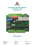
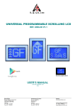
S. & A.S. LTD ELEVATOR CONTROL MODULE 8/9/10/16/24/32 COLLECTIVE – VERSION 3.4 REF. MICROZED V3.4a USER’S MANUAL FOR S/W VERSION 1.00RE2 1136 Beirut Office: Boutros Building 1st Basement Cheikh-el-Ghabi Street Ghabi Beirut 2068 7808 Lebanon Tel: +961 1 216 994 Fax:+961 1 339 600 Headquarters & Factory: S. & A. S. Building Seaside Road Jieh Chouf Lebanon Tel: +961 7 996 333 Fax:+961 7 996 116 Website: www.sascontrollers.com Technical Support & Email: Tel: +961 71 996 333 [email protected] 1 GENERAL DESCRIPTION ........................................................................................................................................... 3 MAIN FEATURES ................................................................................................................................................. 3 1.2 TECHNICAL DATA ............................................................................................................................................... 4 2 TERMINAL DESCRIPTION .......................................................................................................................................... 5 2.1 TERMINAL LAYOUT............................................................................................................................................. 5 2.2 INPUT TERMINALS .............................................................................................................................................. 5 2.3 OUTPUT TERMINALS .......................................................................................................................................... 6 2.3.1 OUTPUT TERMINALS FOR AC 1 SPEED AND AC 2 SPEED...................................................................... 6 2.3.2 OUTPUT TERMINALS FOR VVVF ................................................................................................................ 6 2.3.3 OUTPUT TERMINALS FOR HYDRAULIC..................................................................................................... 6 2.3.4 INDICATOR OUTPUT TERMINALS ................................................................................................................ 7 2.4 INCREMENTAL ENCODER TERMINALS ............................................................................................................ 7 2.5 CALL TERMINALS................................................................................................................................................ 7 2.5.1 CALL TERMINALS LOCATED ON BOARD................................................................................................... 7 2.5.2 CALL TERMINALS ON EXTENSION BOARDS ............................................................................................ 8 2.6 COMMUNICATION TERMINALS CONNECTION............................................................................................... 11 3 CONTENTS OF PAGES DISPLAYED ON LCD ......................................................................................................... 12 4 VIEWING FAULTS AND FAULTS DESCRIPTION .................................................................................................... 12 4.1 HOW TO VIEW THE FAULTS ............................................................................................................................ 12 4.2 HOW TO ERASE THE FAULTS ......................................................................................................................... 12 4.3 FAULT CODE DESCRIPTION ............................................................................................................................ 13 5 MENU......................................................................................................................................................................... 14 5.1 PASSWORD ....................................................................................................................................................... 14 5.2 ACCESSING THE MENU ................................................................................................................................... 14 5.3 MENU DESCRIPTION ........................................................................................................................................ 15 5.3.1 MENU TRANSLATION INTO FRENCH AND ARABIC ................................................................................ 19 5.3.2 ON-BOARD CALL REGISTRATION FUNCTION ........................................................................................ 20 5.3.3 ON-BOARD INSPECTION OPERATION ..................................................................................................... 20 6 DIP SWITCHES FUNCTION DESCRIPTION ............................................................................................................ 21 7 IMPLEMENTAION OF DIRECT APPROACH (USING ENCODER) ........................................................................... 21 7.1 ELEVATOR INSTALLATION............................................................................................................................... 21 7.2 SETTINGS IN THE MAIN MENU ........................................................................................................................ 21 7.3 LEARNING TRIP PROCEDURE ......................................................................................................................... 21 7.4 DISTANCE CALCULATION ................................................................................................................................ 22 8 MANUAL FLOOR ADJUSTMENT .............................................................................................................................. 22 9 INSTALLATION GUIDE ............................................................................................................................................. 23 10 APPENDIX A .............................................................................................................................................................. 24 2 1 GENERAL DESCRIPTION The MicroZed v3.4 elevator controller module contains all the necessary components to control the elevator and to simultaneously insure the protection of the elevator and user against faulty conditions. It can operate in a group of up to 4 elevators. In addition, this module has a user-friendly interface consisting of one 24-characters by 2-lines LCD alphanumeric display and three push buttons to access the different pages, menus and parameters editing (the display is sold separately). The outputs are capable of driving both AC and DC contactors. Controller has an incremental encoder interface used optionally for floor information (Slow down and final stop). All spare outputs are user configurable. In call multiplexing mode, the controller can service up to 16 floors in down collective simplex. Furthermore, the MicroZed v3.4 controller has a serial RS485 port enabling it to be connected to a hand held diagnostic tool (sold separately). A new communication port is implemented. It accepts the following optional interface cards: 1. Serial calls 2. Ethernet interface 3. RS232 interface for GSM modems 1.1 MAIN FEATURES Platform Type Mode Self diagnostic Status information Fault count Shaft information Indicator signal Number of stops Door type 5 Door controls Door parking status Floor Stop time Main landing Car light Automatic return Gong output 7 Inspection mode 8 Reservation 1 Minimum load 9 Full load Emergency stop 10 Firemen operation Terminals Communication Software Microcontroller 1 AC 1 speed – AC 2 speed – VVVF – Hydraulic 1 Simplex or group Fault messages describing common faults related to periphery inputs Status of the elevator and the door are permanently displayed Count of level II faults (refer to section 4.1) is permanently displayed End of shaft in the up direction End of shaft in the down direction Slow down and final stop in the up direction Slow down and final stop in the down direction Door zone (recommended but not obligatory) 2 Car position is saved following a power failure Gray code, provided by the board (binary or other types can be supported optionally) 3 3 3 3 3 3 1 8, 16 , 24 or 32 stops collective down – 6, 11 , 16 or 22 stops collective selective – 4 4 16 stops collective Mul↓ , 9 stops collective MulF 1 Swinging, automatic or ½ automatic door 6 Input for re-open, photocell and door jam switch + input to bypass closing delay 1 Parking with door opened or door closed 1 Can be defined by the user 1 Can be defined as any stop Automatic switch off after preset time To main landing floor Three seconds pulse to signal the arrival of the elevator For installation and maintenance purposes using slow speed System responds to car calls only, outside calls are canceled Car calls are canceled if car stops twice on a car call and no passengers exit car Only car calls are served, outside calls are still registered Car is stopped, car calls canceled, outside calls retained, car restarts on a car call Evacuation to main landing, blocking all calls and allowing firemen operation All terminals are individually labeled according to function to facilitate identification RS-232C port ready for group operation or two way communication with a PC TM Monitoring and controlling elevator installation, software runs under Windows 1 Selection by presetting a parameter in the menu, refer to section 5. When power returns, elevator resumes from where it was without the need of a homing trip unless Power-ON homing is enabled, refer to section 5. 3 Requires optional extension boards. 4 Requires no extension and the elevator must not in group mode. 5 For automatic or ½ automatic door only. 6 Activated by a push button in the car. 7 Activated by an external key switch and two push buttons. 8 Activated by a key switch in the car. 9 Activated by an external contact. 10 Activated by a key switch in the main landing floor. 2 3 1.2 TECHNICAL DATA Supply voltages Inputs Control outputs Call terminals Indicator outputs Connection 1 Board supply: 17vac +15% -25% - 120mA Periphery supply: 22vdc +15% -25% Each input has a led to indicate its status – all inputs are optically isolated Input active voltage level is 22vdc Each output has a led to indicate its status – all outputs are dry relay contacts 1 Rated at 250Vac 10A Each call has a led to indicate its status Each call terminal consists of a combined input/output which is optically isolated Call active voltage level is zero volts (GND) Call terminals are capable of driving lamps up to 3 watts operating on 22vdc Each call terminal is protected by an additional output transistor The + and – supplies of Car and Hall are short circuit protected Each output has a led to indicate its status – all outputs are optically isolated For A,B,C,D,E, LED On: Output voltage level is 22vdc (P) For arrow up and arrow down LED On: Output voltage level is 0vdc (GND) Screw type, plug-in connectors Care should be taken to add a freewheeling diode in parallel with the coil of each DC contactor or DC relay driven from the board. 4 2 TERMINAL DESCRIPTION CT3 CT2 CT1 CT0 17V~ 17V~ CT9 CT8 CT7 CT6 CT5 CT4 CT15 CT14 CT13 CT12 CT11 CT10 P GND + HALL - HALL + CAR - CAR B A E D C ↓↑ 2.2 COM DATA1 DATA2 EOS DNI EOS UPI IP2 IP3 PTC b PTC a SPRE IP1 FRMN DZ VVVF BR FULL LS EC LS EO CLSE RE OPN SFTY ON CONT RDY STP RSV INSP EN INSP DN INSP UP EOS DN EOS UP SDPF DN SDFS UP -5V + AA+ BB+ LOW HI UP DN SOP1 SOP2 SOP3 SOP4 TERMINAL LAYOUT LGHT CLGT OPN CLSE CDOOR CDRV 2.1 INPUT TERMINALS SDFS UP SDFS DN EOS UP EOS DN INSP UP INSP DN INSP EN RSV STP CONT RDY SFTY ON RE OPN CLSE LS EO LS EC FULL VVVF BR DZ FRMN SPRE IP1 PTC a PTC b IP2 IP3 EOS UPI EOS DNI Slow down and final stop in the up direction magnetic switch Slow down and final stop in the down direction magnetic switch End of shaft in the up direction magnetic or limit switch to force slow speed End of shaft in the down direction magnetic or limit switch to force slow speed Inspection up Inspection down Inspection enable (when input is inactive) Reservation – outside calls are canceled (when input is active) Emergency stop (when input is inactive) Should be active prior to initiating travel (ensures that all contactors are in their OFF state) Should be active when lift is moving (used to read the status of the safety circuit) Re-open for automatic door (when inactive) / door closed for swinging door (when active) Bypasses reclosing delay in automatic door Limit switch end of opening Limit switch end of closing Full load – only car calls are served with outside calls still being registered (when input is active) A VVVF signal that prompts the controller that the drive has engaged the mechanical brake Door zone magnetic switch Firemen switch Spare input 1 Input from the PTC Input from the PTC Spare input 2 Overload End of shaft in the up direction magnetic or limit switch to force intermediate speed End of shaft in the down direction magnetic or limit switch to force intermediate speed 5 2.3 OUTPUT TERMINALS 2.3.1 P +22V GND LGHT CLGT OPN CLSE CDOOR CDRV LOW HI UP DN SOP1 SOP2 SOP3 SOP4 2.3.2 P +22V GND LGHT CLGT OPN CLSE CDOOR CDRV LOW HI UP DN SOP1 SOP2 SOP3 SOP4 2.3.3 P +22V GND LGHT CLGT OPN CLSE CDOOR CDRV LOW HI UP DN SOP1 SOP2 SOP3 SOP4 OUTPUT TERMINALS FOR AC 1 SPEED AND AC 2 SPEED 1 Biasing voltage from periphery supply – positive side 1 Biasing voltage from periphery supply – negative side Car light relay Common for LGHT output 2 Open door relay or contactor 3 2 Cam contactor / Close relay or contactor Common for CLSE and OPN outputs Common for DN, UP, HI, LOW and SOP1 outputs Low speed contactor High speed contactor Up direction contactor Down direction contactor Spare output 1 Spare output 2 Spare output 3 Spare output 4 OUTPUT TERMINALS FOR VVVF 4 Biasing voltage from periphery supply – positive side 1 Biasing voltage from periphery supply – negative side Car light relay Common for LGHT output 5 Open door relay or contactor 6 2 Cam contactor / Close relay or contactor Common for CLSE and OPN outputs Common for DN, UP, HI, LOW and SOP1 outputs Low speed contactor High speed contactor Forward contactor Reverse contactor Spare output 1 Spare output 2 Spare output 3 Spare output 4 OUTPUT TERMINALS FOR HYDRAULIC 7 Biasing voltage from periphery supply – positive side 1 Biasing voltage from periphery supply – negative side Car light relay Common for LGHT output 8 Open door relay or contactor 9 2 Cam contactor / Close relay or contactor Common for CLSE and OPN outputs Common for DN, UP, HI, LOW and SOP1 outputs Releveling relay High speed valve Pump delta contactor Down direction valve Spare output 1 Spare output 2 Spare output 3 Spare output 4 1 Although this is not an output, it is listed with the outputs for convenience. For automatic door only. 3 For swinging door. 4 Although this is not an output, it is listed with the outputs for convenience. 5 For automatic door only. 6 For swinging door. 7 Although this is not an output, it is listed with the outputs for convenience. 8 For automatic door only. 9 For swinging door. 2 6 2.3.4 INDICATOR OUTPUT TERMINALS Up direction arrow Down direction arrow Floor information A for Gray code indicator Floor information B for Gray code indicator Floor information C for Gray code indicator Floor information D for Gray code indicator Floor information E for Gray code indicator FACE ↓ A B C D E 2.4 INCREMENTAL ENCODER TERMINALS GND ENC VCC ENC AENC A+ ENC BENC B+ 2.5 2.5.1 Negative supply Positive supply Phase A inverted Phase A Phase B inverted Phase B CALL TERMINALS CALL TERMINALS LOCATED ON BOARD The allocation of calls on call terminals depends on whether one or more extension boards are present. The table below shows how the calls are allocated: Without Extension CT15 CT14 CT13 CT12 CT11 CT10 CT9 CT8 CT7 CT6 CT5 CT4 CT3 CT2 CT1 CT0 17V~ 17V~ 1 Down Collective Down 7 Down 6 Down 5 Down 4 Down 3 Down 2 Down 1 Down 0 Car 7 Car 6 Car 5 Car 4 Car 3 Car 2 Car 1 Car 0 Full Collective Down 5 Down 4 Down 3 Down 2 Down 1 Up 4 Up 3 Up 2 Up 1 Up 0 Car 5 Car 4 Car 3 Car 2 Car 1 Car 0 Board power supply – 17v~ b2 Board power supply – 17v~ b2 Mul↓ Collective Car+Down 15 Car+Down 14 Car+Down 13 Car+Down 12 Car+Down 11 Car+Down 10 Car+Down 9 Car+Down 8 Car+Down 7 Car+Down 6 Car+Down 5 Car+Down 4 Car+Down 3 Car+Down 2 Car+Down 1 Car+Down 0 MulF Collective Down8 Down7 Down6 Down5 Down4 Down3 Down2 Car+Down1 Car+Up7 Car+Up6 Car+Up5 Car+Up4 Car+Up3 Car+Up2 Car+Up1 Car+Up0 With 1 Extension CT15 CT14 CT13 CT12 CT11 CT10 CT9 CT8 CT7 CT6 CT5 CT4 CT3 CT2 CT1 CT0 17V~ 17V~ 1 Down Collective Car 15 Car 14 Car 13 Car 12 Car 11 Car 10 Car 9 Car 8 Car 7 Car 6 Car 5 Car 4 Car 3 Car 2 Car 1 Car 0 Full Collective Up 4 Up 3 Up 2 Up 1 Up 0 Car 10 Car 9 Car 8 Car 7 Car 6 Car 5 Car 4 Car 3 Car 2 Car 1 Car 0 Board power supply – 17v~ b2 Board power supply – 17v~ b2 1 Down calls starting at ground floor level and below are internally converted to up calls. The position of the ground floor is determined by setting the number of basements; refer to section 5. For instance if there are no basements, then the ground floor is on the first level and consequently Down 0 call will be internally interpreted as an Up 0 call. 7 With 2 or 3 Extensions CT15 CT14 CT13 CT12 CT11 CT10 CT9 CT8 CT7 CT6 CT5 CT4 CT3 CT2 CT1 CT0 17V~ 17V~ 2.5.2 1 Down Collective or Full Collective Car 15 Car 14 Car 13 Car 12 Car 11 Car 10 Car 9 Car 8 Car 7 Car 6 Car 5 Car 4 Car 3 Car 2 Car 1 Car 0 2 Board power supply – 17v~ a 2 Board power supply – 17v~ b CALL TERMINALS ON EXTENSION BOARDS If more than one extension board is required, the boards should be cascaded. The table below shows how the calls are allocated on the extension board #1: With 1 Extension P +22V GND EC0 EC1 EC2 EC3 EC4 EC5 EC6 EC7 EC8 EC9 EC10 EC11 EC12 EC13 EC14 EC15 Down Collective 1 Full Collective 2 Biasing voltage from periphery supply – positive side 2 Biasing voltage from periphery supply – negative side Down 0 Up 5 Down 1 Up 6 Down 2 Up 7 Down 3 Up 8 Down 4 Up 9 Down 5 Down 1 Down 6 Down 2 Down 7 Down 3 Down 8 Down 4 Down 9 Down 5 Down 10 Down 6 Down 11 Down 7 Down 12 Down 8 Down 13 Down 9 Down 14 Down 10 Down 15 - 1 Down calls starting at ground floor level and below are internally converted to up calls. The position of the ground floor is determined by setting the number of basements; refer to section 5. For instance if there are no basements, then the ground floor is on the first level and consequently Down 0 call will be internally interpreted as an Up 0 call. 2 Although this is not a call, it is listed with the calls for convenience. 8 With 2 Extensions P +22V GND EC0 EC1 EC2 EC3 EC4 EC5 EC6 EC7 EC8 EC9 EC10 EC11 EC12 EC13 EC14 EC15 With 3 Extensions P +22V GND EC0 EC1 EC2 EC3 EC4 EC5 EC6 EC7 EC8 EC9 EC10 EC11 EC12 EC13 EC14 EC15 Down Collective 1 Full Collective 2 Biasing voltage from periphery supply – positive side 2 Biasing voltage from periphery supply – negative side Down 0 Up 0 Down 1 Up 1 Down 2 Up 2 Down 3 Up 3 Down 4 Up 4 Down 5 Up 5 Down 6 Up 6 Down 7 Up 7 Down 8 Up 8 Down 9 Up 9 Down 10 Up 10 Down 11 Up 11 Down 12 Up 12 Down 13 Up 13 Down 14 Up 14 Down 15 - Down Collective 1 Full Collective 2 Biasing voltage from periphery supply – positive side 2 Biasing voltage from periphery supply – negative side Down 0 Up 0 Down 1 Up 1 Down 2 Up 2 Down 3 Up 3 Down 4 Up 4 Down 5 Up 5 Down 6 Up 6 Down 7 Up 7 Down 8 Up 8 Down 9 Up 9 Down 10 Up 10 Down 11 Up 11 Down 12 Up 12 Down 13 Up 13 Down 14 Up 14 Down 15 Up 15 1 Down calls starting at ground floor level and below are internally converted to up calls. The position of the ground floor is determined by setting the number of basements; refer to section 5. For instance if there are no basements, then the ground floor is on the first level and consequently Down 0 call will be internally interpreted as an Up 0 call. 2 Although this is not a call, it is listed with the calls for convenience. 9 The table below shows how the calls are allocated on the extension board #2: With 2 Extensions P +22V GND EC0 EC1 EC2 EC3 EC4 EC5 EC6 EC7 EC8 EC9 EC10 EC11 EC12 EC13 EC14 EC15 With 3 Extensions P +22V GND EC0 EC1 EC2 EC3 EC4 EC5 EC6 EC7 EC8 EC9 EC10 EC11 EC12 EC13 EC14 EC15 Down Collective 1 Full Collective 2 Biasing voltage from periphery supply – positive side 2 Biasing voltage from periphery supply – negative side Car 16 Down 1 Car 17 Down 2 Car 18 Down 3 Car 19 Down 4 Car 20 Down 5 Car 21 Down 6 Car 22 Down 7 Car 23 Down 8 Down 16 Down 9 Down 17 Down 10 Down 18 Down 11 Down 19 Down 12 Down 20 Down 13 Down 21 Down 14 Down 22 Down 15 Down 23 Down Collective 1 Full Collective 2 Biasing voltage from periphery supply – positive side 2 Biasing voltage from periphery supply – negative side Car 16 Down 1 Car 17 Down 2 Car 18 Down 3 Car 19 Down 4 Car 20 Down 5 Car 21 Down 6 Car 22 Down 7 Car 23 Down 8 Car 24 Down 9 Car 25 Down 10 Car 26 Down 11 Car 27 Down 12 Car 28 Down 13 Car 29 Down 14 Car 30 Down 15 Car 31 Down 16 1 Down calls starting at ground floor level and below are internally converted to up calls. The position of the ground floor is determined by setting the number of basements; refer to section 5. For instance if there are no basements, then the ground floor is on the first level and consequently Down 0 call will be internally interpreted as an Up 0 call. 2 Although this is not a call, it is listed with the calls for convenience. 10 The table below shows how the calls are allocated on the extension board #3 With 3 Extensions P +22V GND EC0 EC1 EC2 EC3 EC4 EC5 EC6 EC7 EC8 EC9 EC10 EC11 EC12 EC13 EC14 EC15 2.6 Down Collective Full Collective 1 Biasing voltage from periphery supply – positive side 1 Biasing voltage from periphery supply – negative side Down 16 Car 16 Down 17 Car 17 Down 18 Car 18 Down 19 Car 19 Down 20 Car 20 Down 21 Car 21 Down 22 Up 16 Down 23 Up 17 Down 24 Up 18 Down 25 Up 19 Down 26 Up 20 Down 27 Down 17 Down 28 Down 18 Down 29 Down 19 Down 30 Down 20 Down 31 Down 21 COMMUNICATION TERMINALS CONNECTION COM, DATA1 and DATA2 should be connected in all controllers in a group mode. 1 Although this is not a call, it is listed with the calls for convenience. 11 3 CONTENTS OF PAGES DISPLAYED ON LCD Page 1 Page 2 Page 3 3 Page 4 4 Page 5 5 Page 6 Page 7 Page 8 4 4.1 Company name, Software version 1 Time, date and day of the week st 1 line: Elevator status Normal, Inspection, Homing, Reservation, Full Load, Landing, Fault, MCIHCAssign 2 Speed Hi, Lo 2 Direction ↑, ↓ Floor FL ## nd 2 line: Door status: For swinging door Opened, Closed, Locking, Locked For automatic & 1/2 automatic door Opened, Closed, Opening, Closing, ½open, Unknown Current fault description Fault Log with the possibility of viewing the last 99 faults with the floor where each fault has occurred Shows the number of MCI-HC detected online If Details is selected, shows the status of MCI-HC on each floor (online/ offline) Homing trip request Summary of the elevator settings: Elevator mode and board address Collective mode Door type Drive type Count of extensions Minimum load feature (MD: Disabled, ME: Enabled) Main Landing feature (LD: Disabled, LE: Enabled) 6 Parking Door status (PDC: Closed, PDO: Opened) Boards detected On Bus (supported only when diagnostic tool is used) VIEWING FAULTS AND FAULTS DESCRIPTION HOW TO VIEW THE FAULTS Faults detected by the board are divided into three levels: 1. Level I faults: faults that block the elevator when they occur. But the elevator can resume operation right after the fault disappears. 2. Level II faults: faults that can be tolerated for a few occurrences before the elevator is blocked by the board. 7 The count of level II faults is shown on LCD Page 4. When the count of level II faults reaches the preset number , the board will block the elevator. 3. Level III faults: faults that the board considers to be fatal and will block any further operation of the elevator. Pressing the Select push button while on LCD Page 4 will prompt the board to start displaying the last 99 faults saved in memory. The board begins by displaying the last fault followed by the floor number where the fault occurred. Press Previous or Next push buttons to display the previous or next fault. 4.2 HOW TO ERASE THE FAULTS To erase the faults as well as the count of level II faults from memory, enter the menu, go to Empty Fault Log and press Select push button. You will be prompted to confirm your request. If Yes is pressed all faults are erased, if No is pressed, faults are not affected. 1 When the RTC device is installed. When the elevator is moving. 3 Appears only if there is a fault. 4 Appears only if fault log is not empty. 5 Appears only if D-CAN board is connected to MicroZed. 6 Relevant in automatic or ½ automatic door. Refer to section 5. 7 Refer to section 5. 2 12 4.3 FAULT CODE DESCRIPTION Fault Message Fault Description Sfty opnd in travl Safety circuit and/or door opened 8 during travel Sfty opnd in travl Safety circuit opened during travel Lock opnd in travl Door clsd, not sfty Fail to lock cam Fail to close door EOS_UP Fault EOS_DN Fault Shaft Info Flt Shaft Info Flt No EOS Info Emergency stop Car is jammed Door is obstructed Fail to open door 9 Operat. days exprd Contactors jammed Motor overheating Level I 9 Door lock circuit opened during 8 travel Safety circuit failed to close after door 9 closing Failure in locking door after 3 8 attempts 9 Failure in closing door EOS-UP fault EOS-DN fault SDFS-UP or SDFS-DN or EOS-UP 3 or EOS-DN or DZ fault SDFS-UP or SDFS-DN or EOS-UP 3 or EOS-DN or DZ fault EOS-UP and EOS-DN faults (both open) Emergency stop Motor has been powered for 25 sec, car did not move Door has been opened for more than 5 Door Obstructed Del Failure in opening door Preset number of operating days expired All orders on contactors were removed, one contactor or more is still engaged Motor temperature has exceeded its maximum allowable operating temperature I I Action taken Waits for safety circuit to close Waits for safety circuit to close, cancels calls 1 if fault persists more than 5sec Waits for lock circuit to close, cancels calls if 1 fault persists more than 5sec 1 I Cancels calls and opens door I Cancels calls II III III Cancels calls, opens door 2 Blocks elevator 2 Blocks elevator II Performs a homing trip II Performs a homing trip III Blocks elevator I Waits for a car call to resume III Blocks elevator I Waits for door to close II Close door and resume III Blocks elevator I Waits all contactors to be released I Elevator is stopped at the nearest floor. Waits for the motor to cool down External err.(VVVF) VVVF external error I Wrong dir. Moving Lift is moving in the opposite direction III No MCI CANx2 Data Serial communication between the Microzed main control panel and MCI-DCAN is corrupted or interrupted I No Data from Cabin CAN bus communication between MCI-DCAN of the Microzed main control and MCI-DCAN of the Microzed cabin control is corrupted or interrupted I 1 1 4 2 6 7 Elevator is stopped at the nearest floor. Waits for external VVVF error to be removed Make sure that lift is going in the right direction, if not switch up and down directions outputs. Otherwise, switch encoder signals Elevator is stopped at the nearest floor. MicroZed cabin control will open the door and wait for the communication to be re-established to resume operation Elevator is stopped at the nearest floor. MicroZed cabin control will open the door and wait for the communication to be re-established to resume operation The last 50 faults are permanently stored along with the time, date of occurrence (if RTC is installed) and the floor where the error occurred. Faults can be accessed through the Select option on LCD Page 4. 1 Waits for a call to resume operation. When the cause of the fault is diagnosed and fixed, empty the faults log or request a homing trip so that the elevator resumes operation. 3 When DZ magnetic switch is installed. Refer to section 5. 4 When the cause of the fault is diagnosed and fixed, the elevator will automatically resume operation. 5 Relevant in duplex mode only - Refer to section 5. 6 In case of automatic door, waits for obstacle to clear. 7 To recover from this fault, access menu and clear the count of elapsed days. Refer to sections 5. 8 For swinging or ½ automatic door. 9 For automatic door. 2 13 5 5.1 MENU PASSWORD A password is required for accessing the menu. The password consists of 6 digits. Two passwords can access the menu. The first is provided by S. & A.S. Co. Ltd. and is referred to as client password. This password can only be changed by S. & A.S. Co. Ltd. The second password is referred to as the user password. The user password can be modified in the menu. The client password accesses all the items in the menu whereas the user password is denied access to all menu items related to time restriction. 5.2 ACCESSING THE MENU 1 To access the menu, press the right most push button on the LCD Display while on pages 1, 2, 3 or 6 . You will be prompted to enter a password. The first digit on the left starts blinking. Use the left most push button to decrement the digit and the middle push button to increment the digit. When the desired digit is reached, push the right most push button. The digit is accepted and replaced by “*”. The next digit starts blinking. Repeat the above procedure for all remaining five digits. If you have entered the right password, access to the menu will be granted, otherwise access will be denied. Note that the push buttons have dynamic functions and their functions are at all times shown on the lower line of the display. 1 Refer to section 3 14 5.3 MENU DESCRIPTION What you see on the display V100RE2 Normal FLxx View Faults (Fatal=--) Homing trip? Simplex(1)Full Swinging Simulate calls Inspection operation Boards detected On Bus Enter Password Empty Fault Log Light Time Floor Stopping Time Parking Door Description and Comments Hydraulic Star Time VVVF Start Delay VVVF/ Hyd Stop Delay Empties the fault log Car light turn off delay in sec Time between travel in sec The parking status of the door When disabled, the RE OPN input is bypassed to clear any obstacle blocking the door/ When enabled and the door is held open, it is considered to be obstructed after this delay Star starting time of the hydraulic pump The delay in sec between providing direction and speed reference outputs The delay in sec between removing direction and speed reference outputs Gong Time The gong time in seconds Door Nudging/Obst Minimum Load Main Landing PTC Detection 6 Power On Homing Light Inverted Re-leveling 1 When this feature is enabled, car calls are canceled if car stops twice on a car call and no passengers exit car Sets the landing floor along with the delay before making a main landing trip given that the elevator has no calls to serve When this feature is enabled, the motor PTC is continuously monitored When enabled, the elevator makes a homing trip upon every power-on When disabled following power on and if lift is not parked on a floor , the controller will take it to the nearest floor traveling in the same direction prior to power failure When set to NoDZ and the lift is on a floor, no action is taken. Otherwise, lift will do homing trip upon power-on When this feature is enabled, the output logic of the car light is inverted When preset to selective, the re-leveling is done only when the door is closed and the elevator has no calls to serve V means visible A means accessible 3 NV means not visible 4 NA means not accessible 5 N/A means not assigned 6 If there are 2 close floors or the elevator slips more than ½ distance of the floor, “Power On Homing” must be set to enabled 7 Appears only if drive is VVVF and Encoder is installed 2 Normal Insp Mode Mode 1 V V V V If faults exist V V V V 2 3 4 V/A NV /NA NV/NA V/A if DT exists V/A V/A if faults exist A A A A A A Visibility Condition 5 Default Value Range N/A N/A Auto/Half Auto door 5 to 99sec 1.0 to 9.9sec Opened/Closed 10sec 3.0sec Closed Ena/ Dis, 5 to 99sec Dis, 90sec A A N/A A A A A A A 0.0 to 9.9sec -9.9 to 9.9sec -9.9 to 9.9sec 1.0sec 1.0sec 3.0sec A A Hydraulic elevator VVVF drive VVVF drive Spare1 or Spare2 function=gong 0.0 to 7.5sec 3.0sec A A N/A Disabled/Enabled Disabled A A N/A A A N/A A A N/A A A N/A A A Hydraulic elevator None, 0… 310’10” to 9’59” Disabled/Enabled Disabled/Enabled/ NoDZ Disabled/Enabled Always/Selective/ Dist(mm) 10 to 100 7 None Disabled Disabled Disabled Selective/ 10 What you see on the display EOS During Insp Cam close delay Cam engage time Contactor start del Update Counter Offset Applied Time Restrict. Elapsed Cnt Of Days Preset Count Of Days Max. Count Of Err. Car jammed delay Auto Door Operation Inspection speed Ramp to stop w Insp Basements Door Type Description and Comments When this feature is enabled, the elevator is prevented from crossing the end of shaft limits in inspection mode The delay in seconds between the closing of the swinging door and the Cam /Close signal Maximum delay in seconds to Sfty on after engaging the cam The delay in seconds between providing the Cam/Close signal and the direction/Speed outputs Selects when the floor distance counter is updated Offsets the difference in distance when on all floors lift traveling down stops lower or higher than the position at which it stops when it is traveling up for the same floor. Value shown is the last offset applied. When this feature is enabled, the elevator is blocked when the number of days counted reaches the preset count of days Shows the number of days elapsed since the Time Restriction feature was enabled or since the last reset of the Elapsed Cnt Of Days Sets the maximum count of days of operation Sets the maximum count of Level II faults before blocking the elevator The car is considered jammed after this delay. The Auto door is considered jammed after this delay Sets the inspection speed When this feature is enabled, the lift will ramp to stop when the inspection up or down button is released Sets the count of basements Selects the type of the elevator door. Select ½ automatic door if there is an electric cam to lock the door in addition to the automatic door drive. Pre-opening When this feature is enabled, the door closing signal is permanently engaged during travel (required for specific types of door drives) Sets the logic of the re-opn input When this feature is set to Y and the door is counting Floor Stopping Time to start closing, Then if the photocell is cut, Restart counting Floor Stopping Time When this feature is installed, the controller looks for the DZ magnetic switch signal upon every floor stop. The absence of this signal on floor level prompts the controller to register a Level II fault and to perform a homing trip When this feature is enabled, door starts opening when DZ is reached First Stop Selects the gray code output for the first stop Permanent Close RE-OPN i/p Reset time on re-opn Door Zone Normal Mode Insp Mode Visibility Condition Range Default Value A A N/A Disabled / Enabled Disabled A A Swinging door 0.0 to 7.5sec 0.0 sec 1 A Swinging door 5 to 99sec 5 sec A 2 A A N/A 0.0 to 7.5sec 0.5sec NA A VVVF Drive & Encoder installed Always/At stop/ At Start Always NA A VVVF Drive & Encoder installed -9.9999 to +9.9999 0.0000 A A Client P/W Disabled / Enabled Disabled A A Client P/W N/A A A A A A A A A A A Client P/W N/A N/A Auto/Half Auto door Not VVVF drive 1 to 999 None, 1…99 Dis, 5 to 99sec Dis, 5 to 99sec Lo/Hi 1 10 25sec 20sec Lo ِA A VVVF drive Dis/Ena Dis 3 NA A N/A 0 NA A N/A 0 to 9 Swinging/ Automatic / ½ Automatic A A Automatic door Disabled/Enabled Disabled A A N/A no/nc nc A A Auto/Half Auto door N/Y N A A N/A None/Installed None A A DZ installed Disabled / Enabled Disabled A A N/A 0/1 0 Swinging 1 A means accessible N/A means not assigned NA means not accessible 2 3 16 What you see on the display Description and Comments Normal Mode Insp Mode Visibility Condition Collective Selects between collective selective, down collective and multiplexing modes NA A N/A Carcall priority Gives priority to car calls over hall calls NA A Encoder Set to installed to implement direct approach NA A Pulses/Revolution Roping Nominal RPM Machine speed m/s HiSpd reached (m) IntSpd reached (m) LoSpd reached (m) SlowDown dist. m Int. SlowDown m Lo SlowDown m NA NA NA NA 1 NA NA NA NA NA NA A A A A 2 A A A A A A NA A Mode Sets the count of pulses per revolution of the incremental encoder Selects the roping ratio of the installation Nominal RPM of machine Sets the speed of the machine Distance traveled to accelerate from zero to high speed Distance traveled to accelerate from zero to intermediate speed Distance traveled to accelerate from zero to low speed Distance traveled to decelerate from high speed to zero Distance traveled to decelerate from intermediate speed to zero Distance traveled to decelerate from low speed to zero Sets the count of extension boards installed and thus the distribution of the car and land calls Selects between simplex and group modes. Collective#APB VVVF Drive & Door Zone installed Encoder installed Encoder installed Encoder installed Encoder installed Encoder installed Encoder installed Encoder installed Encoder installed Encoder installed Encoder installed NA Drive Selects the drive type Intermediat Speed Homing Speed Extension Boards Range Full / Down / APB / Mul↓/ MulF N/Y Default Value Down N None / Installed None 0 to 9999 1:1, 2:1 or 4:1 0 to 9999 0 to 9.999 0 to 9.999 0 to 9.999 0 to 9.999 0 to 9.999 0 to 9.999 0 to 9.999 1024 1:1 1500 2.000 3.500 1.400 0.060 3.500 1.400 0.060 N/A None, 1, 2 or 3 None A N/A NA A N/A Simplex/Group AC 2speed / Hydraulic / VVVF Simplex AC 2speed Selects when intermediate speed is used NA A None, 1FL, 2FL None Select the homing speed NA A Insp/ Hi/ Int Insp Fan/Gong/Int.Speed/ Base Block4/Out Of Serv. /Door Buzzer Fan 3 VVVF drive & Encoder not installed VVVF drive Spare1 Sets the Spare1 output function NA A Not Hydraulic Spare2 Sets the Spare2 output function NA A Not 1/2 Auto. door Spare3 Sets the Spare3 output function NA A Spare4 Sets the Spare4 output function NA A Passenger Capacity Sets the passenger capacity of the elevator A A Group mode Display Type Selects the hall and car display type A A N/A Total Trips Counter for the number of trips made by the elevator. The counter value can be edited and modified A A N/A Fan/Gong/Int.Speed/ Base Block4/Out Of Serv. / Hyd Up Valve5/ Door Buzzer Fan/Gong/Int.Speed/ Base Block4/Out Of Serv. / Hyd Up Valve5/Door Buzzer Fan/Gong/Int.Speed/ Base Block4/Out Of Serv. / Hyd Up Valve5/Door Buzzer 1 to 99 Gray / Binary / Enhanced 0 to 999999 Gong Out Of Serv. Fan 5 Gray N/A 1 NA means not accessible A means accessible 3 N/A means not assigned 4 Int Speed and Base Block appear only in VVVF drive 5 Hyd Up Valve appears only in hydraulic drive 2 17 Normal Mode Insp Mode Visibility Condition Sets the language A A N/A A A A 1 A A A A A N/A Client P/W N/A SAS P/W A A RTC installed N/A Adjust Time Adjust Date Adjust Day Upload settings to DT Dnload settings from DT Sets the address of the board (each board in a group must have a unique address) Shows and edits the user password Shows and edits the company name displayed on the first page Shows if the RTC Device is installed. Shows the maximum recorded count of trips in one hour along with the time of the day when it happened Sets the time of the day Sets the date Sets the day of the week Upload the settings from MicroZed to DT Download the settings from DT to MicroZed English / French / Arabic 1 to 4 ****** 16 characters None / Installed A A A A 3 NA A A A A A N/A N/A Mon to Sun Learning trip Initiates a learning trip to calculate all floor positions A NA Manual Floor adjustment Allow manual floor position adjustment A A NA ِA RTC installed RTC installed RTC installed DT connected DT connected VVVF drive & Encoder installed VVVF drive & Encoder installed VVVF drive & Encoder installed NA A NA A A A NA A A A A A What you see on the display Description and Comments Language Board Address User Password Co. RTC Device Max Trips/h Calc. HiSpd Distances Calc. IntSpd Distances Calc. LoSpd Distances 4 MCI-HC Assignment? Load Factory Settings Exit Menu Temporarily Exit Menu Initiates a trip to calculate the distance traveled to accelerate from zero to high speed as well as distance traveled to decelerate from high speed to zero Initiates a trip to calculate the distance traveled to accelerate from zero to intermediate speed as well as distance traveled to decelerate from intermediate speed to zero Initiates a trip to calculate the distance traveled to accelerate from zero to low speed as well as distance traveled to decelerate from low speed to zero Selects Hall calls assignment mode that configures hall call boards to corresponding floors Loads the settings of the factory Exits the menu allowing reentry with no password for 10 minutes Exits the menu VVVF drive & Encoder installed VVVF drive & Encoder installed MCI-DCAN connected to MicroZed N/A N/A N/A Range Default Value English 1 000000 2 N/A N/A N/A N/A N/A N/A N/A 1 Hyd Up Valve appears only in hydraulic drive N/A means not assigned 3 NA means not accessible 4 Refer to MCI DCAN+MCI HC Catalog to configure hall call boards to corresponding floors 2 18 5.3.1 MENU TRANSLATION INTO FRENCH AND ARABIC ENGLISH V100RE2 Normal FLxx View Faults (Fatal=--) Homing trip? Simplex(1)Full Swinging Simulate calls Inspection operation Boards detected On Bus Enter Password Empty Fault Log Light Time Floor Stopping Time Parking Door Door Nudging/Obs Hydraulic Star Time VVVF Start Delay VVVF/Hyd Stop Delay Gong Time Minimum Load Main Landing PTC Detection Power On Homing Light Inverted Re-leveling EOS During Insp Cam close delay Cam engage time Contactor start del Update Counter Offset Applied Time Restrict. Elapsed Cnt Of Days Preset Count Of Days Max. Count Of Err. Car jammed delay Auto Door Operation Inspection speed Ramp to stop w Insp Basements Door Type Permanent Close RE-OPN i/p Reset time on re-opn Door Zone Pre-opening First Stop Collective Carcall priority Encoder Pulses/Revolution Roping Nominal RPM Machine speed m/s HiSpd reached (m) IntSpd reached (m) LoSpd reached (m) SlowDown dist. m Int. SlowDown m Lo SlowDown m Extension Boards Mode FRENCH V100RE2 Normal Etxx Voir Fautes (Fatal=--) Parcours d'initialisat. Simplex(1)Sel. Battante Simuler appels Operation Revision Cartes detectees sur Bus Entrer Le Code Vider Journal De Fautes Duree D'eclairage Duree Arret Etage Stationemt Porte Porte Coup/Coincee Duree Etoile Hydr. Delai Depart VVVF Delai Arret VVVF Duree Gong Charge Minimale Retour Et.Pr. Detection PTC Initial. & EDL Eclair. Inverse Corrig. Niveau EOS Et Revision Delai fermetu. serr Duree fermetu. serr Delai Depart Cont. Compteur Offset Appliq. Compteur Jours Jours Deroules Nb. De Jours Desires Nbre Max. D'erreurs Delai cabine bloquee Operation porte auto. Vitesse de Revision Ramp avec revision Sous-sols Type De Porte Ferm.Permanente Entree RE-OPN Reset dure apres reopn Door Zone Pre-ouverture Premier Arret Collective Priorite pour cabine Encoder Pouls/Revolution Corde RPM nominale Vitesse machine m/s GV atteinte (m) VInt atteinte VPetite atteinte (m) Ralentissage m Ralentissage Int m Ralentissage Lo m Nbre D'extensions Mode ARABIC 100RE2 طأ دي (--=) ار ا ء ر أو ول !ب دي#$ (1)د )آة ا &ت *)+ , -. ا/ دة010 ت0 ي2 ا3 ا4أد ) ا ء56 7ا ءة86 ا93و :! ا/ ف03<ة و ا&ب:30ا :/ة#ا&ب وآ ?@ ه<رو,B$ <ة VVVF عC36 اDE VVVF ف030 اDE ر0#<ة ا /$ اد4,)ا 4< GDE PTC س2 رE-ر أو 0@I 58ا ى0K2 7)LE *)+ + 01 أ ل3 اDE ل3<ة ا ر0K@KNع آC3O اDE Update Counter Offset Applied 930< اPE QPN,م اS<د ا مS< <د اS<)E طCT <د ا/L3أ < ورI! P !Iا UE0E !ب أو, *)ل اC 2ا *)+ V )<ار$ا 2<د ادوار ا ع ا&ب0$ 5ق داCTا RE-OPN 4< :! ا/ ف030 <اد ا0) ى ا&ب0K2 :&2 7K+ / او30ا V,BE !I Q+أ #,ا دورة/X&$ 4&)ا Nominal RPM N@, ا HiSpd. غ0! +2 IntSpd. غ0! +2 LoSpd. غ0! +2 Z & ا+2 Int Z & ا+2 Lo Z & ا+2 +Q ت0 <د <IL 19 ENGLISH Drive Intermediat Speed Homing Speed Spare1 Spare2 Spare3 Spare4 Passenger Capacity Display Type Total Trips Language Board Address User Password Co. RTC Device Max Trips/h Adjust Time Adjust Date Adjust Day Upload settings to DT Dnload settings from DT Learning trip Manual Floor adjustment Calc. HiSpd Distances Calc. IntSpd Distances Calc. LoSpd Distances MCI-HC Assignment? Load Factory Settings Exit Menu Temporarily Exit Menu 5.3.2 FRENCH Moteur Vitesse intermed. Vitesse initialisat. Spare1 Spare2 Spare3 Spare4 Nbre de personnes Type d'afficheur Nb. De Parcours Langage Adresse de la carte Code Utilisateur Co. RTC Parcrs Max/h Ajuster L'heure Ajuster La Date Ajuster Le Jour Enregistrer param.sur DT Telecharger param. du DT Parcours d’apprentissage Ajustement manuel etages Calc. Distances de GV Calc. Distances de VInt Calc. Distances de PV? Affectation MCI-HC? Configuration Initiale Sortie temporaire Menu Sortir Du Menu ARABIC )ك,ا 0K ر أو 1?+8ا 2?+8ا 3?+8ا 4?+8ا ص.]<د ا ]^,ا تC<اد ا _ا 0ان ا0N ?N ي3ر ]آ RTC س/ تC ر/L3أ 930 ا-&8 aSرK ا-&8 م0 ا-&8 DT / -&Q اb DT G -&Q ا4S#NE IE ر :!ا0 S<وS S02E ؟VS2ت ا+2 G,.E ؟-0ت ا+2 G,.E ؟Z &ت ا+2 G,.E ؟MCI-HC GIE VNL, ا3 ادة )56 اG 93^ وج )56 اG وج ON-BOARD CALL REGISTRATION FUNCTION The operator can give calls using the page “Simulate calls” to test the lift. Lift has to be in normal operation with no faults. When SELECT is pressed, the display will show FL#. Use the PREV and NEXT push buttons to change the floor selection. Once the desired floor is displayed, press SELECT push button, the display will show the calls available on the floor selected. Push the appropriate button, the call for this floor is registered and the appropriate led will light on the board as well as in the car or hall. The lift will proceed to serve this call. If no buttons are pressed within 5 seconds, the display will exit the call registration mode. The display will exit the floor selection mode if no buttons are pressed for 5 seconds. 5.3.3 ON-BOARD INSPECTION OPERATION The display has to be on “Inspection operation” page. Lift has to be in inspection mode. When SELECT is pressed, the NEXT and PREV push buttons acts as INSP_DN and INSP_UP inputs respectively. To exit the inspection direction mode, press SELECT push button. The board will also exit the inspection direction mode if no buttons are pressed within 10 seconds. The INSP_DN and INSP_UP inputs have higher priority and will override the NEXT and PREV push buttons. 20 6 DIP SWITCHES FUNCTION DESCRIPTION ON 1 2 3 4 ON = Encoder is powered from MicroZed v3.4a Not used OFF = Hardware implementation of EOS DNI and EOS UPI is enabled, this mean whenever EOS DNI/EOS UPI opens when lift is going in the down/up direction, SOP1 relay (intermediate speed) will engage OFF = Hardware implementation of EOS DN and EOS UP is activated, this mean whenever EOS DN/EOS UP opens when lift is going in the down/up direction, LOW _SPD relay will engage 7 IMPLEMENTAION OF DIRECT APPROACH (USING ENCODER) 7.1 1. 2. 3. 4. 5. ELEVATOR INSTALLATION The elevator must be in inspection mode. DZ magnetic switches must be installed. EOS UP and EOS DN must be installed at a distance of 1 m from last floor and first floor respectively. EOS UP1 and EOS DN1 must be installed at a distance of 1.5 m from last floor and first floor respectively. Encoder must be connected to MicroZed v3.4a controller. 7.2 SETTINGS IN THE MAIN MENU 1. Set the “Drive” type to VVVF. 2. Set “Door Zone” to installed. 3. Set “VVVF Start Delay” and “VVVF/ Hyd Stop Delay” depending on the VVVF type used (“VVVF/ Hyd Stop Delay” should be greater than time required to decelerate from high speed to zero). 4. Set “Endocer” to installed. 5. Set “Pulses/Revolution”, “Roping”, “Machine speed m/s” and “Nominal RPM” to their appropriate values. 6. Set “Homing Speed” to inspection speed. 7. Set “Spare1” output to intermediate speed. 8. Make sure that lift is going in the right direction (when inspection up, ↑ green led must be ON and when insp dn, ↓ red led must be ON). If not switch Up and DN direction outputs. Otherwise, switch encoder signals. 7.3 1. 2. 3. 4. LEARNING TRIP PROCEDURE Adjust the elevator at a position about 1m above EOS DN. Set Dip switches 1 and 2 to ON. Set the elevator to normal mode. The display will show “Must do a Learning trip”. Enter to the menu and select “Learning trip” 1, Select yes when “Are you sure?” message appears. 1 To do Learning trip, Collective type must not be set to MUL↓ or MULF. Otherwise, the controller will prompt the user to change the collective type and will give this message ” Modify collective type to Down or Full” 21 5. The controller starts learning trip at homing speed. 6. At the end of learning trip procedure, “Learning trip succeeded” message is displayed for 2 seconds. 7. After the learning trip, the user is prompted to save the results. “Save procedure result” message appears on the display. 8. If Yes is selected, the results are saved and the controller does a homing trip and stops on floor 0. 9. If No is selected, then the message “Must do a Learning trip” will reappear. 7.4 DISTANCE CALCULATION 1. Set the elevator to inspection mode. 2. Implement the necessary tuning on the VVVF drive to ensure close tracking of reference speed. 3. Adjust the position of the elevator on floor1 with DZ magnetic switch active. 4. Set the elevator to normal mode. 5. Enter to the menu and select “Calc. HiSpd Distances “, Select yes when “Are you sure?” message appears. 6. At the end of high speed distance calculation, “Calculate distance succeeded” message is displayed for 2 seconds. 7. After the calculation, the user is prompted to save the result where “Save procedure result” message appears on the display. 8. Select yes to save the result. 9. Repeat from step 4 while selecting “Calc. IntSpd Distances “. 10. Repeat from step 4 while selecting “Calc. LoSpd Distances “. 11. When all the 3 distances are calculated, do homing trip. 12. Adjust the position of EOS DN and EOS UP to “Int. SlowDown m” minus 5cm from floor0 and last floor levels respectively (Not from DZ edge). 13. Adjust the position of EOS DNI and EOS UPI to “SlowDown dist. m” minus 5cm from floor0 and last floor levels respectively (Not from DZ edge). 14. Set Dip switches 1 and 2 to off to activate hardware implementation EOS UP, EOS DN, EOS UPI and EOS DNI. 8 MANUAL FLOOR ADJUSTMENT Manual floor adjustment allows the installer to fine-tune the floor stopping position of the lift and should only be done after learning trip procedure and distance calculation. Normally, if all DZ flags (or magnets) are accurately positioned on the floor level, no additional floor tuning would be necessary. To manually adjust the floor level, the following steps must be implemented: 1. Put lift in normal mode 2. Give a car call to the lowest floor and record in a table the floor stopping position next to floor 0 and proceed by giving car calls to stop on all the floors in the building and on each stop record the difference in the floor stopping position next to the corresponding floor starting from floor1. It is good practice to use positive values for stops lower than the floor position and to use negative values for stops higher than the floor positions. 3. Enter the menu and go to “Manual Floor Adjustment” 4. Starting from floor 0, edit to position and add to it the value recorded in the table next to floor0 5. Repeat step4 for all subsequent floors 6. Give a car call to floor 0, Check to floor stopping position which should be correct by now 7. Repeat step6 for all subsequent floors 8. Proceed from last floor by giving a car call to the floor before last floor and record the difference in the floor stopping position if any (more than 5mm) 9. Repeat step8 until floor0 is reached 10. If there is a constant difference in the floor stopping position, enter the menu and go to “Offset Applied”, edit it and put this value and press enter. Note that the display will always show the value of the last offset applied. For instance, if an offset of 20mm is applied, the display will always show 20mm. To undo this offset and return to zero offset, the user needs to apply an offset of -20mm and not an offset of zero. 22 9 INSTALLATION GUIDE For the following analysis, we are assuming that the PTC is either disabled or properly connected, the DZ magnetic switch is not installed and its parameter in the menu is set accordingly and EOS during Insp is disabled. Step 1 • • Install and wire the panel according to wiring diagrams provided by the panel assembler. Double-check all connections. Step 2 • • • • Make sure that the board is in the Inspection Mode (Inspection switch should be opened) Power the panel. The floor number may be unknown (FL--). This is normal and it indicates that the board does not have a previous car position in memory. As soon as the elevator is switched from inspection to normal operation, it will make a homing trip and floor display will show 0 when the elevator reaches the first stop. If all safety circuits are closed, inspection up and inspection down push buttons are active (therefore inspection travel only requires the closing of safety circuit). Below is a visual indication of what the status of the input LEDs should be so that the elevator operates in the inspection mode: SDFS SDFS EOS EOS INSP INSP INSP RSV STP CONT SFTY RE CLSE LS LS FULL VVVF DZ FRMN SPRE IP2 IP3 EOS EOS DN UP DN UP UP DN EN RDY ON OPN EO EC BR IN UPI DNI Automatic door (Door open) 1 Automatic door (Door closed) 2 Swinging door Status Irrelevant Input Inactive (OFF) Input Active (ON) Step 3 • • • Using the elevator in the inspection mode, adjust the position of all magnets according to the layout provided on the MICROZED V3.4 WIRING DIAGRAM – INPUTS (SHEET 3 of 10); refer to section 10 APPENDIX A. If you are using bi-stable magnetic switches, proceed with inspection travel to terminal floors to properly set their contacts. When you finish, and prior to changing the operating mode from inspection to normal, the inputs should look as follows (given that elevator is on any intermediate floor and on floor level): SDFS SDFS EOS EOS INSP INSP INSP RSV STP CONT SFTY RE CLSE LS LS FULL VVVF DZ FRMN SPRE IP2 IP3 EOS EOS DN UP DN UP UP DN EN RDY ON OPN EO EC BR IN UP1 DN1 Automatic door Swinging door Status Irrelevant • • Input Inactive (OFF) Input Active (ON) Refer to section 5 to set all internal parameters according to the site’s requirements. Change operating mode from INSPECTION to NORMAL. Elevator should proceed with its homing trip and will stop on the floor level of the first floor. 1 When an inspection up or down is given, board proceeds by closing the door before moving. Door is then kept closed. This applies also for ½ automatic door. 2 This applies also for ½ automatic door. 23 10 APPENDIX A This appendix contains all wiring diagrams relevant to assembling the board in a panel. 24