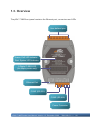
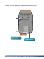
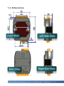
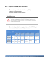
1
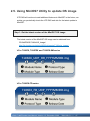
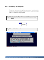
μPAC-7186E Series User Manual Service and usage information for µPAC-7186EX µPAC-7186PEX µPAC-7186EX-FD µPAC-7186EX-SM µPAC-7186EXD µPAC-7186PEXD µPAC-7186EXD-FD µPAC-7186EXD-SM Written by Liam Lin Edited by Anna Huang µPAC-7186E Series User Manual, Version 1.2, December 2009 7MH-022-01 ----- 1 Warranty All products manufactured by ICP DAS are under warranty regarding defective materials for a period of one year, beginning from the date of delivery to the original purchaser. Warning ICP DAS assumes no liability for any damage resulting from the use of this product.ICP DAS reserves the right to change this manual at any time without notice. The information furnished by ICP DAS is believed to be accurate and reliable. However, no responsibility is assumed by ICP DAS for its use, not for any infringements of patents or other rights of third parties resulting from its use. Copyright Copyright @ 2009 by ICP DAS Co., Ltd. All rights are reserved. Trademark The names used for identification only may be registered trademarks of their respective companies. Contact US If you have any problem, please feel free to contact us. You can count on us for quick response. Email: [email protected] µPAC-7186E Series User Manual, Version 1.2, December 2009 7MH-022-01 ----- 2 Table of Contents 1. Introduction .......................................................................................6 1.1. Features ....................................................................................................... 8 1.2. Specifications ............................................................................................. 12 1.2.1. μPAC-7186E/μPAC-7186EXD .......................................................... 12 1.2.2. μPAC-7186PEX/μPAC-7186PEXD .................................................. 14 1.2.3. μPAC-7186EX-SM/μPAC-7186EXD-SM .......................................... 16 1.2.4. μPAC-7186EX-FD/μPAC-7186EXD-FD ........................................... 18 1.3. Overview .................................................................................................... 20 1.4. Dimensions ................................................................................................ 22 1.5. Companion CD........................................................................................... 23 2. Getting Started ................................................................................ 24 2.1. Hardware Installation ................................................................................. 24 2.1.1. Mounting the Hardware .................................................................... 24 2.1.2. Setting up the Power Supply and Networking .................................. 27 2.2. Software Installation ................................................................................... 28 2.3. Configuring the Boot Mode......................................................................... 30 2.4. Using MiniOS7 Utility to download programs ............................................. 31 2.4.1. Establishing a connection between the PC and the µPAC-7186E ... 31 2.4.2. Uploading and executing programs on µPAC-7186E ....................... 45 2.4.3. Making programs start automatically ............................................... 46 2.5. Using MiniOS7 Utility to update OS image ................................................. 47 3. Your First Program on µPAC-7186E...............................................50 3.1. Setting up the compiler .............................................................................. 50 3.1.1. Installing the compiler ...................................................................... 51 3.1.2. Setting up the environment variables ............................................... 55 3.2. API for μPAC-7186E................................................................................... 58 3.3. Build and run your first program ................................................................. 63 µPAC-7186E Series User Manual, Version 1.2, December 2009 7MH-022-01 ----- 3 4. API and Demo Reference ............................................................... 74 4.1. API for COM Port ....................................................................................... 76 4.1.1. Types of COM port functions ............................................................ 77 4.1.2. API for MiniOS7 COM port ............................................................... 78 4.1.3. API for standard COM port ............................................................... 81 4.1.4. Comparison between MiniOS7 and Standard COM port function .... 84 4.1.5. Request/Response protocol define on COM port ............................. 86 4.2. API for I/O Modules .................................................................................... 87 4.3. API for EEPROM ........................................................................................ 89 4.4. API for Flash Memory ................................................................................. 91 4.5. API for NVRAM and RTC ........................................................................... 93 4.6. API for 5-Digital LED .................................................................................. 96 4.7. API for Timer .............................................................................................. 98 4.8. API for WatchDog Timer (WDT) ............................................................... 100 4.9. API for MFS (For µPAC-7186EX-FD series only) ..................................... 102 Appendix A. Frame Ground ............................................................. 108 Appendix B. What is MiniOS7? ........................................................ 109 Appendix C. What is MiniOS7 Utility? ............................................. 110 Appendix D. What is MiniOS7 File System (MFS)? ........................ 111 Appendix F. More C Compiler Settings ........................................... 114 F.1. Turbo C 2.01............................................................................................. 114 F.2. BC++ 3.1. IDE .......................................................................................... 117 F.3. MSC 6.00 ................................................................................................. 121 F.4. MSVC 1.50 ............................................................................................... 123 Appendix G. Application of RS-485 Network .................................. 127 G.1. Basic RS-485 network ............................................................................. 127 G.2. Daisy chain RS-485 network ................................................................... 128 µPAC-7186E Series User Manual, Version 1.2, December 2009 7MH-022-01 ----- 4 G.3. Star type RS-485 network ....................................................................... 129 G.4. Random RS-485 network ........................................................................ 131 G.5. µPAC-7186E Master-Slave Mode............................................................ 132 G.5.1. µPAC-7186E as a Master .............................................................. 133 G.5.2. µPAC-7186E as a slave ................................................................ 135 µPAC-7186E Series User Manual, Version 1.2, December 2009 7MH-022-01 ----- 5 1. Introduction The µPAC-7186E is a palm-size programmable automation controller that with Ethernet, RS-232, RS-485 communication. ICP DAS provides easy-to-use software development tool kits (Xserver, VxComm, Modbus libraries). Users can use them to easily integrate serial devices to have Ethernet/Internet communication ability and through the standard Modbus protocol to communicate with SCADA software (Indusoft, ISaGARF, DasyLab, Trace Mode, Citect, iFix, etc.). For the hardware, it also supports an I/O expansion bus. The I/O expansion bus can be used to implement various I/O functions such as D/I, D/O, A/D, D/A, Timer/Counter, UART, flash memory, battery backup SRAM, ASIC key & other I/O functions. Nearly all kinds of I/O functions can be implemented by this bus but the bus can support only one board. There are more than 50 boards available for µPAC-7186E, you can choose one of them to expand hardware features. Tips & Warnings In the descriptions in this manual, “µPAC-7186E” means “μPAC-7186E” and “μPAC-7186PEX” series product. The only difference between the two series product is that the μPAC-7186PEX can receive power from an Ethernet cable when added to a PoE enabled network; the μPAC-7186E can receive power from power input terminal only. µPAC-7186E Series User Manual, Version 1.2, December 2009 7MH-022-01 ----- 6 The features of μPAC-7186PEX differ from µPAC-7186E Compared to µPAC-7186E, µPAC-7186PEX equips with an integrated IEEE 802.3af Power-over-Ethernet (PoE) that allows power and data to be carried over a single Ethernet cable, so a device can operate solely from the power it receives through the data cable. This innovation allows greater flexibility in office design, higher efficiency in systems design, and faster turnaround time in set-up and implementation. The features of μPAC-7186EX-FD differ from µPAC-7186E Compared to µPAC-7186E, uPAC-718EX-FD equips with an extra 64MB flash memory. By using the built-in MFS (MiniOS7 File System) library, you can freely read/write files from/to the 64MB flash memory. Simply with the uPAC-786EX-FD, many kinds of data-logging applications become a piece of cake! For example, log analog signals with timeline, or log RS-232/485 data for further analysis. Package List One μPAC-7186E module Quick Start Guide Software Utility CD RS-232 Cable µPAC-7186E Series User Manual, Version 1.2, December 2009 7MH-022-01 ----- 7 1.1. Features Support for Virtual COM technology Using the VxComm technology, PC can create virtual COM ports to map the RS-232, RS-485 of the μPAC-7186E. The software running on the PC can operate the virtual COM ports like a standard COM port to access the serial devices connect to the μPAC-7186E. That is to say, the original software developed for the serial devices can access the serial devices via the Ethernet/Internet without any modification. Each PC can control up to 256 COM ports (including real COM ports). Using the I/O expansion board, each μPAC-7186E can have up to 8 COM ports. Support Modbus Protocol Using the Modbus firmware, μPAC-7186E offers following Modbus features: * Modbus/TCP/RTU/ASCII slave * Modbus/TCP/RTU/ASCII master * Gateway for Modbus/TCP to Modbus/RTU µPAC-7186E Series User Manual, Version 1.2, December 2009 7MH-022-01 ----- 8 Easy-to-use software development tool kits (using C language) If the default firmware does not totally fulfill the user's application needs, custom firmware can be easily developed with using the SDK (Xserver, Modbus library) provided by ICP DAS. Ethernet protocols TCP, UDP, IP, ICMP, ARP Support web configuration µPAC-7186E has a built-in web server for configuration. You can use standard web browsers (such as IE, Netscape, Firefox,., .etc) to configure its Ethernet and COM ports configurations. Remote configuration/maintenance μPAC-7186E can be operated via the Ethernet (TCP/IP or UDP) or RS-232, to allow tasks such as downloading programs, configuration, updating the MiniOS7, etc. Built-in watchdog timer (WDT) μPAC-7186E include an internal watchdog timer (WDT). The watchdog timer will trigger a system reset if the main program fails or neglects to regularly service the watchdog. The intention is to bring the system back from the hung state into normal operation. I/O expansion bus interface The μPAC-7186E supports the use of an I/O expansion bus to add a single I/O Expansion Board. ICP DAS provides all function libraries for I/O Expansion Boards to enable easy use of the I/O Expansion Board functions. µPAC-7186E Series User Manual, Version 1.2, December 2009 7MH-022-01 ----- 9 Support PoE (for μPAC-7186PEX series only) The μPAC-7186PEX feature true IEEE 802.3af-compliant (classification, Class 1) Power over Ethernet (PoE) using both Ethernet pairs (Category 5 Ethernet cable). μPAC-7186PEX can receive power from an auxiliary power sources like AC adapters and battery in addition to the PoE enabled network. This is a desirable feature when the total system power requirements exceed the PSE's load capacity. Furthermore, with the auxiliary power option, the μPAC-7186PEX can be used in a standard Ethernet (non-PoE) system. MiniOS7 file system (MFS) (for μPAC-7186EX-FD series only) Can dynamically read/write/append data to files continuously The 64MB flash memory is divided to 2 disks, each disk can store 456 files max. You can create files and then write/append data to it. Then read data in the file and forward to PC for posted analysis when the data is complete collected. Provides C language API Following functions are similar to the functions that turbo C and Borland C provide. This helps users to be familiar to MFS with a short learning curve. mfs_OpenFile, mfs_CloseFile, mfs_ReadFile, mfs_WriteFile, mfs_Gets, mfs_Puts, mfs_Getc, mfs_Putc, mfs_EOF, mfs_Seek, mfs_Tell, mfs_DeleteFile, mfs_DeleteAllFiles, mfs_GetFileInfoByName, mfs_GetFileInfoByNo, … etc. µPAC-7186E Series User Manual, Version 1.2, December 2009 7MH-022-01 ----- 10 Writing Verification Data written to flash memory are read back to verify its correction. The function can be disabled to increase writing speed. But for data safety, we recommend users to enable the function. Automate file system recovery in the event of unexpected reset or power losses When an unexpected reset or power loss occurs, closed files, and files opened for reading are never at risk. Only writing data has risk to be lost. MFS writes data to the flash memory just after executing writing functions (such as mfs_WriteFile, mfs_Puts, mfs_Putc, etc.). And meanwhile, MFS stores important information (such as file name, pointer, flash location, etc) to NVRAM (non-volatile random access memory). When an unexpected reset or power loss occurs, only data written since the last writing operation (such as mfs_WriteFile, mfs_Puts, mfs_Putc, etc.) could be lost. After the MFS reboots, it refers the information stored in the NVRAM to restores the file system. The un-closed writing file will be automatically closed and all its data written before the last writing operation will be safe. µPAC-7186E Series User Manual, Version 1.2, December 2009 7MH-022-01 ----- 11 1.2. Specifications 1.2.1. μPAC-7186EX/μPAC-7186EXD CPU CPU 80186 or compatible (16-bit and 80 MHz) SRAM 512 KB Flash 512 KB, erase unit is one sector (64K bytes); 100,000 erase/write cycles. EEPROM 16 KB, data retention: 40 years; 1,000,000 erase/write cycles. NVRAM 31 Bytes (Battery backup, data valid up to 10 years) RTC (Real Time Clock) RTC Provide seconds, minutes, hours, date of week/month; month and year, valid from 1980 to 2079 64-bit Hardware Serial Number Yes Built-in Watchdog Timer Yes (0.8 second) Communication Interface COM1 RS-232 (TxD, RxD, CTS, RTS and GND); Non-isolated COM2 RS-485 (D2+, D2-; self-tuner ASIC inside); Non-isolated Ethernet Port 10/100Base-TX Ethernet Controller (Auto-negotiating, Auto_MDIX, LED indicator) COM Port Formats Data bit 7, 8 Parity Even, Odd, None Stop bit 1 LED Display 5-Digit 7 Segment LED Display Yes (for μPAC-7186EXD only) System LED Indicator Yes µPAC-7186E Series User Manual, Version 1.2, December 2009 7MH-022-01 ----- 12 Hardware Expansion I/O Expansion Bus Yes User Defined I/O Pins 14 Pins Dimensions WxHxD 72 mm x 123 mm x 35 mm Operating Environment Operating Temperature -25°C ~ +75°C Storage Temperature -40°C ~ +80°C Relative Humidity 5 ~ 90% RH, non-condensing Power Protection Power reverse polarity protection Frame Ground for ESD Protection Yes Required Supply Voltage +10 ~ +30 VDC (non-regulated) Power consumption 1.5 W for μPAC-7186EX 2.5 W for μPAC-7186EXD µPAC-7186E Series User Manual, Version 1.2, December 2009 7MH-022-01 ----- 13 1.2.2. μPAC-7186PEX/μPAC-7186PEXD CPU CPU 80186 or compatible (16-bit and 80 MHz) SRAM 512 KB Flash 512 KB, erase unit is one sector (64K bytes); 100,000 erase/write cycles. EEPROM 16 KB, data retention: 40 years; 1,000,000 erase/write cycles. NVRAM 31 Bytes (Battery backup, data valid up to 10 years) RTC (Real Time Clock) RTC Provide seconds, minutes, hours, date of week/month; month and year, valid from 1980 to 2079 64-bit Hardware Serial Number Yes Built-in Watchdog Timer Yes (0.8 second) Communication Interface COM1 RS-232 (TxD, RxD, CTS, RTS and GND); Non-isolated COM2 RS-485 (D2+, D2-; self-tuner ASIC inside); Non-isolated Ethernet Port 10/100Base-TX Ethernet Controller (Auto-negotiating, Auto_MDIX, LED indicator) COM Port Formats Data bit 7, 8 Parity Even, Odd, None Stop bit 1 LED Display 5-Digit 7 Segment LED Display Yes (for μPAC-7186PEXD only) System/PoE LED Indicator Yes (Red/Green) µPAC-7186E Series User Manual, Version 1.2, December 2009 7MH-022-01 ----- 14 Hardware Expansion I/O Expansion Bus Yes User Defined I/O Pins 14 Pins Dimensions WxHxD 72 mm x 123 mm x 35 mm Operating Environment Operating Temperature -25°C ~ +75°C Storage Temperature -40°C ~ +80°C Relative Humidity 5 ~ 90% RH, non-condensing Power IEEE 802.3af Class 1 Protection Power reverse polarity protection Required Supply Voltage Powered by Power-Over-Ethernet (PoE) or auxiliary power +12 ~ 48 VDC (non-regulated) Power consumption 1.5 W for μPAC-7186PEX 2.5 W for μPAC-7186PEXD µPAC-7186E Series User Manual, Version 1.2, December 2009 7MH-022-01 ----- 15 1.2.3. μPAC-7186EX-SM/μPAC-7186EXD-SM CPU CPU 80186 or compatible (16-bit and 80 MHz) SRAM 640 KB Flash 512 KB, erase unit is one sector (64K bytes); 100,000 erase/write cycles. EEPROM 16 KB, data retention: 40 years; 1,000,000 erase/write cycles. NVRAM 31 Bytes (Battery backup, data valid up to 10 years) RTC (Real Time Clock) RTC Provide seconds, minutes, hours, date of week/month; month and year, valid from 1980 to 2079 64-bit Hardware Serial Number Yes Built-in Watchdog Timer Yes (0.8 second) Communication Interface COM1 RS-232 (TxD, RxD, CTS, RTS and GND); Non-isolated COM2 RS-485 (D2+, D2-; self-tuner ASIC inside); Non-isolated Ethernet Port 10/100Base-TX Ethernet Controller (Auto-negotiating, Auto_MDIX, LED indicator) COM Port Formats Data bit 7, 8 Parity Even, Odd, None Stop bit 1 LED Display 5-Digit 7 Segment LED Display Yes (for μPAC-7186EXD-SM only) System LED Indicator Yes µPAC-7186E Series User Manual, Version 1.2, December 2009 7MH-022-01 ----- 16 Hardware Expansion I/O Expansion Bus Yes User Defined I/O Pins 14 Pins Dimensions WxHxD 72 mm x 123 mm x 35 mm Operating Environment Operating Temperature -25°C ~ +75°C Storage Temperature -40°C ~ +80°C Relative Humidity 5 ~ 90% RH, non-condensing Power Protection Power reverse polarity protection Frame Ground for ESD Protection Yes Required Supply Voltage +10 ~ +30 VDC (non-regulated) Power consumption μPAC-7186EX-SM: 2W μPAC-7186EXD-SM: 3W µPAC-7186E Series User Manual, Version 1.2, December 2009 7MH-022-01 ----- 17 1.2.4. μPAC-7186EX-FD/μPAC-7186EXD-FD CPU CPU 80186 or compatible (16-bit and 80 MHz) SRAM 512 KB Flash 512 KB, erase unit is one sector (64K bytes); 100,000 erase/write cycles. Flash Disk 64M x 8 Bit, data retention: 10 years; 100,000 erase/write cycles. EEPROM 16 KB, data retention: 40 years; 1,000,000 erase/write cycles. NVRAM 31 Bytes (Battery backup, data valid up to 10 years) RTC (Real Time Clock) RTC Provide seconds, minutes, hours, date of week/month; month and year, valid from 1980 to 2079 64-bit Hardware Serial Number Yes Built-in Watchdog Timer Yes (0.8 second) Communication Interface COM1 RS-232 (TxD, RxD, CTS, RTS and GND); Non-isolated COM2 RS-485 (D2+, D2-; self-tuner ASIC inside); Non-isolated Ethernet Port 10/100Base-TX Ethernet Controller (Auto-negotiating, Auto_MDIX, LED indicator) COM Port Formats Data bit 7, 8 Parity Even, Odd, None Stop bit 1 µPAC-7186E Series User Manual, Version 1.2, December 2009 7MH-022-01 ----- 18 LED Display 5-Digit 7 Segment LED Display Yes (for μPAC-7186EXD-FD only) System LED Indicator Yes Hardware Expansion I/O Expansion Bus Yes User Defined I/O Pins 14 Pins Dimensions WxHxD 72 mm x 123 mm x 35 mm Operating Environment Operating Temperature -25°C ~ +75°C Storage Temperature -40°C ~ +80°C Relative Humidity 5 ~ 90% RH, non-condensing Power Protection Power reverse polarity protection Frame Ground for ESD Protection Yes Required Supply Voltage +10 ~ +30 VDC (non-regulated) Power consumption μPAC-7186EX-FD: 2W μPAC-7186EXD-FD: 3W µPAC-7186E Series User Manual, Version 1.2, December 2009 7MH-022-01 ----- 19 1.3. Overview The μPAC-7186E front panel contains the Ethernet port, connectors and LEDs. User-defined pins Green: PoE LED indicator Red: System LED indicator 5-Digital 7-SEG LED (for display series only) Ethernet Port COM1 (RS-232) COM2 (RS-485) Power Connector µPAC-7186E Series User Manual, Version 1.2, December 2009 7MH-022-01 ----- 20 The μPAC-7186E back panel contains the frame ground and Init/Normal Switch Frame Ground Init/Normal Switch µPAC-7186E Series User Manual, Version 1.2, December 2009 7MH-022-01 ----- 21 1.4. Dimensions µPAC-7186E Series User Manual, Version 1.2, December 2009 7MH-022-01 ----- 22 1.5. Companion CD This package comes with a CD that provides drivers, software utility, all of the required documentations…, etc. All of them are listed below. CD:\Napdos 7186e Demo Basic Framework Xserver Document Firmware VoComm OS_Image PC_Tool MiniOS7_Studio MiniOS7_Utility PC_Test_Program PCDiag Vxcomm_Utility µPAC-7186E Series User Manual, Version 1.2, December 2009 7MH-022-01 ----- 23 2. Getting Started If you are a new user, begin with this chapter, it includes a guided tour that provides a basic overview of installing, configuring and using the μPAC-7186E. 2.1. Hardware Installation 2.1.1. Mounting the Hardware The μPAC-7186E can be mounted with the bottom of the chassis on the DIN rail, the wall or piggyback. DIN Rail mounting The μPAC-7186E has simple rail clips for mounting reliably on a standard 35 mm DIN rail. µPAC-7186E Series User Manual, Version 1.2, December 2009 7MH-022-01 ----- 24 Mounting on DIN Rail Remounting from DIN Rail 1 3 2 2 3 1 Din Rail Mountable Model Three Din rail mountable models are available to mount a variety of ICP DAS devices. Each is made of stainless steel and has a ground wire at the end. Part number Maximum number of modules Dimensions DRS-125 2 125 mm x 35 mm DRS-240 3 240 mm x 35 mm DRS-360 5 360 mm x 35 mm µPAC-7186E Series User Manual, Version 1.2, December 2009 7MH-022-01 ----- 25 Piggyback Mounting The μPAC-7186E has two holes on both sides for piggyback mounting µPAC-7186E Series User Manual, Version 1.2, December 2009 7MH-022-01 ----- 26 2.1.2. Setting up the Power Supply and Networking to PC The μPAC-7186E is equipped with an RJ-45 Ethernet port for connection to an Ethernet hub/switch and PC Non-PoE PoE µPAC-7186E Series User Manual, Version 1.2, December 2009 7MH-022-01 ----- 27 2.2. Software Installation All software resources are included on the companion CD. The following steps will help you to install the resources and software from the companion CD. Step 1: Copy the “Demo” folder from the companion CD to PC The folder is an essential resource for users developing custom programs which contains libraries, header files, demo programs and more information as shown below. CD: \Napdos 7186e Demo Basic 7K87K_for_COM COM_Ports .. . Timer Framework FW_Demo01_Client FW_Demo02_Server .. . Lib Xserver XDemo04_Basic XDemo07_printCom1 .. . XDemo14_7Seg_LED Demo_History_YYYYMMDD.txt µPAC-7186E Series User Manual, Version 1.2, December 2009 7MH-022-01 ----- 28 Step 2: Install the MiniOS7 Utility The MiniOS7 Utility is a useful tool that provides a quick and easy way to update OS image or firmware, configure Ethernet settings, and download files to μPAC-7186E from PC. The MiniOS7 Utility can be obtained from companion CD or our FTP site: CD:\Napdos\minios7\utility\minios7_utility\ ftp://ftp.icpdas.com/pub/cd/8000cd/napdos/minios7/utility/minios7_utility/ µPAC-7186E Series User Manual, Version 1.2, December 2009 7MH-022-01 ----- 29 2.3. Configuring the Boot Mode The μPAC-7186E has two operating modes that can be determined by the switch mechanism on the chassis. Init Mode Init mode is a way to use MiniOS7 configuration mode Init Normal Normal Mode Normal mode: Firmware running mode Init Normal Normal mode is the default mode of operation and the one you will use most of the time. Use this mode for more tasks and configurations. Programs also are executed in this mode. Move the switch to the Normal position after the update is complete µPAC-7186E Series User Manual, Version 1.2, December 2009 7MH-022-01 ----- 30 2.4. Using MiniOS7 Utility to download programs Before you begin using the MiniOS7 Utility to download programs, ensure that the controller is connected to the Host PC. The download process has the following main steps: 1. Establishing a connection 2. Download and executing programs on the controller 3. Making programs start automatically All of these main steps will be described in detail later. 2.4.1. Establishing a connection between the PC and the µPAC-7186E There are three ways to establish a connection between the PC and the μPAC-7186E 1. COM1 connection 2. UDP connection 3. TCP connection UDP or TCP COM1 Each of the connection types will be described in detail later. µPAC-7186E Series User Manual, Version 1.2, December 2009 7MH-022-01 ----- 31 2.4.1.1. Steps to use a COM1 connection To connect to the PC using a COM1 connection, please follow the instructions below. Step 1: Turn the switch to “Init” position Init Step 2: Use RS-232 Cable (CA-0910) to connect to PC COM1 µPAC-7186E Series User Manual, Version 1.2, December 2009 7MH-022-01 ----- 32 Step 3: Run the MiniOS7 Utility Step 4: Click the “New connection” function from the “Connection” menu Step 5: On the “Connection” tab of the “Connection” dialog box, select “COM1” from the drop down list, and then click “OK” µPAC-7186E Series User Manual, Version 1.2, December 2009 7MH-022-01 ----- 33 Step 6: The connection has already established Connection Status µPAC-7186E Series User Manual, Version 1.2, December 2009 7MH-022-01 ----- 34 2.4.1.2. Steps to use a UDP connection To connect to the PC using a UDP connection, please follow the instructions below. Step 1: Turn the switch to “Init” position Init Step 2: Use an Ethernet cable to connect to PC UDP µPAC-7186E Series User Manual, Version 1.2, December 2009 7MH-022-01 ----- 35 Step 3: Run the MiniOS7 Utility Step 4: Click the “Search” function from the “Connection” menu Step 5: On the “MiniOS7 Scan” dialog box, choose the module name from the list and then choose “IP setting” from the toolbar µPAC-7186E Series User Manual, Version 1.2, December 2009 7MH-022-01 ----- 36 Step 6: On the “IP Setting” dialog, configure the “IP” settings and then click the “Set” button Step 7: On the “Confirm” dialog box, click “Yes” µPAC-7186E Series User Manual, Version 1.2, December 2009 7MH-022-01 ----- 37 Step 8: Click the “New connection” function from the “Connection” menu Step 9: On the “Connection” tab of the “Connection” dialog box, select “UDP” from the drop down list, type the IP address which you are assigned, and then click “OK” µPAC-7186E Series User Manual, Version 1.2, December 2009 7MH-022-01 ----- 38 Step 10: The connection has already established Connection Status µPAC-7186E Series User Manual, Version 1.2, December 2009 7MH-022-01 ----- 39 2.4.1.3. Steps to use a TCP connection TCP/IP connection only can be created when the module runs VxComm driver, the steps to upload firmware and execute are illustrated in section “2.4.2. Uploading and executing programs on µPAC-7186E” To connect to the PC using a TCP connection, please follow the instructions below. Step 1: Turn the switch to “Init” position Init Step 2: Use an Ethernet cable to connect to PC TCP µPAC-7186E Series User Manual, Version 1.2, December 2009 7MH-022-01 ----- 40 Step 3: Run the VxComm driver The VxComm driver is located at: CD:\NAPDOS\7186e\Firmware\VxComm\Server(7186e)\7186E X\ ftp://ftp.icpdas.com/pub/cd/8000cd/napdos/7186e/firmware/vxc omm/server(7186e)/7186ex/ Step 4: Run the MiniOS7 Utility Step 5: Click the “Search” function from the “Connection” menu Step 6: On the “MiniOS7 Scan” dialog box, choose the module name from the list and then choose “IP setting” from the toolbar µPAC-7186E Series User Manual, Version 1.2, December 2009 7MH-022-01 ----- 41 Step 7: On the “IP Setting” dialog, configure the “IP” settings and then click the “Set” button Step 8: On the “Confirm” dialog box, click “Yes” µPAC-7186E Series User Manual, Version 1.2, December 2009 7MH-022-01 ----- 42 Step 9: Click the “New connection” function from the “Connection” menu Step 10: On the “Connection” tab of the “Connection” dialog box, select “TCP” from the drop down list, type the IP address which you are assigned, and then click “OK” µPAC-7186E Series User Manual, Version 1.2, December 2009 7MH-022-01 ----- 43 Step 11: The connection has already established Connection Status µPAC-7186E Series User Manual, Version 1.2, December 2009 7MH-022-01 ----- 44 2.4.2. Uploading and executing programs on µPAC-7186E Step 1: On the PC side, right click the file name that you wish to download and then select the “Upload” PC side Controller side Step 2: On the controller side, right click the file name that you wish to execute and then select the “Run” µPAC-7186E Series User Manual, Version 1.2, December 2009 7MH-022-01 ----- 45 2.4.3. Making programs start automatically After download programs on the µPAC-7186E, if you need programs to start automatically after the µPAC-7186E start-up, it is easy to achieve it, to create a batch file called autoexec.bat and then upload it on the µPAC-7186E, the program will start automatically in the next start-up. For example, to make the program “hello” run on start-up. One is the “Hello” application file, and the other is the “autoexec.bat” batch file Tips & Warnings Before restaring the module for settings to take effect, you must first turn the switch to “Normal” position. µPAC-7186E Series User Manual, Version 1.2, December 2009 7MH-022-01 ----- 46 2.5. Using MiniOS7 Utility to update OS image ICP DAS will continue to add additional features to MiniOS7 in the future, we advise you periodically check the ICP DAS web site for the latest update to MiniOS7. Step 1: Get the latest version of the MiniOS7 OS image The latest version of the MiniOS7 OS image can be obtained from: CD:\NAPDOS\7186e\OS_Image\ http://ftp.Icpdas.com/pub/cd/8000cd/napdos/7186e/os_image/ For 7186EX, 7186PEX and 7186EX-SM series 7186EX_UDP_HR_YYYYMMDD.img For 7186EX-FD series 7186EX_FD_UDP_YYYYMMDD.img µPAC-7186E Series User Manual, Version 1.2, December 2009 7MH-022-01 ----- 47 Step 2: Establish a connection For more detailed information about this process, please refer to section “2.4.1. Establishing a connection” Step 3: Click the “Update MiniOS7 Image …” from the “File” menu Step 4: Select the latest version of the MiniOS7 OS image µPAC-7186E Series User Manual, Version 1.2, December 2009 7MH-022-01 ----- 48 Step 5: Click the “OK” Step 6: Click the “Info” from the “Command” menu to check the version of the OS image µPAC-7186E Series User Manual, Version 1.2, December 2009 7MH-022-01 ----- 49 3. Your First Program on µPAC-7186E Before writing your first program, ensure that you have the necessary C/C++ compiler and the corresponding functions library on your system. 3.1. Setting up the compiler The following compilers are available for µPAC-7186E. Turbo C++ Version 1.01 Turbo C Version 2.01 Borland C++ Versions 3.1 - 5.2.x MSC MSVC ++ Tips & Warnings ICP DAS suggests that the Borland C++ version compiler is used as the libraries provided on the companion CD have been created using this compiler. Special attention should be paid to the following items before using the compiler to develop custom applications: Generate a standard DOS executable program Set the CPU option to 80188/80186 Set the floating point option to EMULATION if floating point computation is required. (Be sure not to choose 8087) Cancel the Debug Information function as this helps to reduce program size. (MiniOS7 supports this feature.). µPAC-7186E Series User Manual, Version 1.2, December 2009 7MH-022-01 ----- 50 3.1.1. Installing the compiler If there is no compiler currently installed on your system, installation of the compiler should be the first step. The following section guides you to install Turbo C++ Version 1.01 on your system. Step 1: Double click the Turbo C++ executable file to start setup wizard Step 2: Press “Enter” to continue µPAC-7186E Series User Manual, Version 1.2, December 2009 7MH-022-01 ----- 51 Step 3: Enter the letter of the hard drive you wish to install the software Step 4: Enter the path to the directory you wish to install files to µPAC-7186E Series User Manual, Version 1.2, December 2009 7MH-022-01 ----- 52 Step 5: Select “Start Installation” to begin the install process Step 6: Press any key to continue µPAC-7186E Series User Manual, Version 1.2, December 2009 7MH-022-01 ----- 53 Step 7: Press any key to continue Step 8: Installation is complete µPAC-7186E Series User Manual, Version 1.2, December 2009 7MH-022-01 ----- 54 3.1.2. Setting up the environment variables After installing the compiler, several compilers will be available from the Windows Command line. You can set the path environment variable so that you can execute this compiler on the command line by entering simple names, rather than by using their full path names. Step 1: Right click on the “My Computer” icon on your desktop and select the “Properties” menu option Right-click “My Computer” and then select “Properties” µPAC-7186E Series User Manual, Version 1.2, December 2009 7MH-022-01 ----- 55 Step 2: On the “System Properties” dialog box, click the “Environment Variables”button located under the “Advanced” sheet Step 3: On the “Environment Variables” dialog box, click the “Edit” button located in the “System variables” option 1 2 3 4 µPAC-7186E Series User Manual, Version 1.2, December 2009 7MH-022-01 ----- 56 Step 4: Add the target directory to the end of the variable value field A semi-colon is used as the separator between variable values. For example, ”;c:\TC\BIN\;c:\TC\INCLUDE\” Step 5: Restart the computer to allow your changes to take effect µPAC-7186E Series User Manual, Version 1.2, December 2009 7MH-022-01 ----- 57 3.2. API for μPAC-7186E To develop a custom program, ensure that the files below are installed the PC. If they are not installed, refer to “section 2.2. Software Installation”. Functions Library ─ 7186e.lib This file contains the MiniOS7 API (Application Programming Interface) and has hundreds of pre-defined functions related to μPAC-7186E Header File ─ 7186e.h This file contains the forward declarations of subroutines, variables, and other identifiers used for the MiniOS7 API. COM Ports Others (MISC) EEPROM Flash Memory Standard IO Programmable IO MiniOS7 API Functions NVRAM and RTC Files SRAM Timer and WatchDog Timer 5-Digit LED µPAC-7186E Series User Manual, Version 1.2, December 2009 7MH-022-01 ----- 58 System Structure µPAC-7186E Series User Manual, Version 1.2, December 2009 7MH-022-01 ----- 59 Basic: Demos developed from main() Xserver: Demos developed based on Xserver library. Xserver is a library for TCP/IP server applications. With an addional modbus library, users can develop programs with 1. Modbus/TCP slave 2. Modbus/TCP client 3. Modbus/RTU slave 4. Modbus/RTU client 5. Modbus/ASCII slave 6. Modbus/ASCII client 7. Modbus/TCP to Modbus/RTU gateway The Modbus library and demos can be obtained from: CD:\Napdos\Modbus\7186EX\Demo\ µPAC-7186E Series User Manual, Version 1.2, December 2009 7MH-022-01 ----- 60 MiniOS7 Framework Solution: Demos developed based on MiniOS7 framwork. MiniOS7 framework is a library for general TCP/IP applications. It is second generation library of Xserver and is much flexible and powerful than the Xserver. Base on it, users can quickly and easily develop programs with 1. TCP Client 2. TCP Server 3. Web Server 4. UDP Client 5. UDP Server With an additional Modbus library, users can develop programs with 1. Modbus/TCP slave 2. Modbus/TCP client 3. Modbus/RTU slave 4. Modbus/RTU client 5. Modbus/ASCII slave 6. Modbus/ASCII client 7. Modbus/TCP to Modbus/RTU gateway The Modbus library and demos can be obtained from: CD:\Napdos\Modbus\7186EX\Demo\ µPAC-7186E Series User Manual, Version 1.2, December 2009 7MH-022-01 ----- 61 For full usage information regarding the description, prototype and the arguments of the functions, please refer to the “MiniOS7 API Functions User Manual” located at: CD:\Napdos\MiniOS7\Document http://ftp.Icpdas.com/pub/cd/8000cd/napdos/minios7/document/ µPAC-7186E Series User Manual, Version 1.2, December 2009 7MH-022-01 ----- 62 3.3. Build and run your first program If you don‟t use the TC++ (Turbo C++) to write a program, please take the following steps. Step 1: Open a MS-DOS command prompt i. Select “Run” from the “Start” menu ii. On the “Run” dialog box, type “cmd” iii. Click the “OK” button 2. Type “cmd” 3 1 µPAC-7186E Series User Manual, Version 1.2, December 2009 7MH-022-01 ----- 63 Step 2: At the command prompt, type “TC” and then press “Enter” Step 3: Select “New” from the “File” menu to create a new source file µPAC-7186E Series User Manual, Version 1.2, December 2009 7MH-022-01 ----- 64 Step 4: Type the following code. Note that the code is case-sensitive #include “7186e.h” /* Include the header file that allows 8000e.lib functions to be used */ void main(void) { InitLib(); /* Initiate the 7186e library */ Print(“Hello world!\r\n”); /* Print the message on the screen */ } µPAC-7186E Series User Manual, Version 1.2, December 2009 7MH-022-01 ----- 65 Step 5: Save the source file i. Select “Save” from the “File” menu ii. Type the file name “Hello” iii. Select “OK” Tips & Warnings You can write the code as shown below with your familiar text editor or other tools; please note that you must save the source code under a filename that terminates with the extension “C”. µPAC-7186E Series User Manual, Version 1.2, December 2009 7MH-022-01 ----- 66 Step 6: Create a project (*.prj) i. Select “Open project…” from the “Project” menu ii. Type the project name “Hello” iii. Select “OK” iv. Select “Add” v. Select “Done” to exit µPAC-7186E Series User Manual, Version 1.2, December 2009 7MH-022-01 ----- 67 Step 8: Add the necessary function libraries to the project (*.lib) i. Select “Add item…” from the “Project” menu ii. Type “ *.LIB ” to display a list of all available function libraries iii. Choose the function libraries you require iv. Select “Add” v. Select “Done” to exit µPAC-7186E Series User Manual, Version 1.2, December 2009 7MH-022-01 ----- 68 Step 9: Set the memory model to large i. Select “Compiler” from the “Options” menu and then select “Code generation…” ii. On “Model” option, select “Large” iii. Select “OK” µPAC-7186E Series User Manual, Version 1.2, December 2009 7MH-022-01 ----- 69 Step 10: Set the memory model to large i. Select “Compiler” from the “Options” menu and then select “Advanced code generation…” ii. On “Floating Point” option, select “Emulation” iii. On “Instruction Set” option, select “80186” iv. Select “OK” µPAC-7186E Series User Manual, Version 1.2, December 2009 7MH-022-01 ----- 70 Step 11: Set the memory model to large i. Select “Directories…” from the “Options” menu ii. On “Include Directories” option, specify the header file iii. On “Library Directories” option, specify the function library file iv. Select “OK” µPAC-7186E Series User Manual, Version 1.2, December 2009 7MH-022-01 ----- 71 Step 12: Select “Build all” from the “Compile” menu to build the project µPAC-7186E Series User Manual, Version 1.2, December 2009 7MH-022-01 ----- 72 Step 13: Use the MiniOS7 Utility to connect the µPAC-7186E For more detailed information about this process, please refer to section “2.3.1. Establishing a connection” Making programs start automatically One is the “Hello” application file, and the other is the “autoexec.bat” batch file µPAC-7186E Series User Manual, Version 1.2, December 2009 7MH-022-01 ----- 73 4. API and Demo Reference There are several demo programs that have been designed for µPAC-7186E. You can examine the demo source code, which includes numerous comments, to familiarize yourself with the MiniOS7 APIs and quickly develop your own applications quickly by modifying these demo programs. Basic Folder Demo Explanation Config_1_Basic Reads information from a text file (basic). Config_2_Advanced Reads a config file (text file) (advanced). File Hello_C Hello_C++ Reads the library version and flash memory size. Reset Resets the software. Runprog Illustrates how to select an item and run it. Serial Illustrates how to retrieve 64-bit hardware unique serial number. Watchdog Enables the WDT or bypasses the enable WatchDog function. Hello Misc Shows how to write a value to the Memory EEPROM Memory Flash Shows how to write and erase the Flash. Led Shows how to control the red LED display. Seg7led Shows how to control the red 7-segment display. DateTime DateTime Shows how to read and write the date and time from the RTC. 7K87K_Module 7K87K_DI_for_Com Shows LED EEPROM. how µPAC-7186E Series User Manual, Version 1.2, December 2009 to connect and 7MH-022-01 ----- 74 Folder Demo Explanation 7K87K_DO_for_Com control the 7K or 87K series modules via COM2. 7K87K_AI_for_Com AO_22_26_for_Com AO_024_for_Com (1) Shows how to write a function to input data. C_Style_IO Com port Receive (2) Shows how to receive a string. (3) Shows how to use a C function: sscanf or just use Scanf() Receives data from COM port. Slv_COM.c is in non-blocked mode Receive.c is in blocked mode. A slave COM Port demo for Slv_COM (request/reply) (command/response) applications. or ToCom_In_Out Illustrates how to Read/Write byte data via COM Port. Utiliy Utility for the MiniOS7 File System. Operations Include Dir, Read, Write, etc. Quality assurance program for the 7186FD (for 64MB MFS_QA flash memory on µPAC-7186EX-FD) MiniOS7 File System. Including function test, performance test. read/write Puts How to write a string to a file in the 64MB flash memory Gets How to get a string from a file in the 64MB flash memory For more information about these demo programs, please refer to: CD:\NAPDOS\7186e\Demo\Basic\bc_tc\ http://ftp.Icpdas.com/pub/cd/8000cd/napdos/7186e/demo/basic/bc_tc/ µPAC-7186E Series User Manual, Version 1.2, December 2009 7MH-022-01 ----- 75 4.1. API for COM Port The μPAC-7186E provides two built-in COM ports, COM1 and COM2. COM1 – An RS-232 port that can use to connect to PC. COM2 – An RS-485 port that can use in a point to point connection. COM1 COM2 µPAC-7186E Series User Manual, Version 1.2, December 2009 7MH-022-01 ----- 76 4.1.1. Types of COM port functions There are two types of functions below for using COM port. 1. MiniOS7 COM port functions 2. (C style) Standard COM port functions Tips & Warnings You have the alternative of MiniOS7 COM ports functions or (C style) Standard COM port functions. If you choose the ones, then another cannot be used. Summarize the results of the comparison between MiniOS7 COM port functions and (C style) Standard COM port functions: Kinds of COM Functions Port Buffer Functions RX TX Check data 1 KB 1 KB IsCom() ToCom() ReadCom() printCom() MiniOS7 COM port 1, 2, etc. (C style) Standard COM port 1 512 256 Kbhit() (Note) Bytes Bytes Send data Puts() Putch() µPAC-7186E Series User Manual, Version 1.2, December 2009 Read data Getch() Show data Print() 7MH-022-01 ----- 77 4.1.2. API for MiniOS7 COM port API for using COM ports 1. InstallCom() Before any COM Port can be used, the driver must be installed by calling InstallCom(). 2. RestoreCom() If the program calls InstallCom(), the RestoreCom()must be called to restore the COM Port driver. API for checking if there is any data in the COM port input buffer 3. IsCom() Before reading data from COM port, the IsCom() must be called to check whether there is any data currently in the COM port input buffer. API for reading data from COM ports 4. ReadCom() After IsCom() confirms that the input buffer contains data, the ReadCom() must be called to read the data from the COM port input buffer. API for sending data to COM ports 5. ToCom() Before sending data to COM ports, the ToCom() must be called to send data to COM ports. µPAC-7186E Series User Manual, Version 1.2, December 2009 7MH-022-01 ----- 78 For example, reading and receiving data through the COM1. #include <stdio.h> #include “7186e.h” void main(void) { int quit=0, data; InitLib(); /* Initiate the 7186e library */ InstallCom(1, 115200, 8, 0, 1); /* Install the COM1 driver */ while(!quit) { if(IsCom(1)) /* Check if there is any data in the COM port input buffer */ { data=ReadCom(1); ToCom(1, data); /* Read data from COM1 port */ /* Send data via COM1 port */ if(data==‟q‟) quit=1; /* If „q‟ is received, exit the program */ } } RestoreCom(1); /* Uninstall the COM1 driver */ } µPAC-7186E Series User Manual, Version 1.2, December 2009 7MH-022-01 ----- 79 API for showing data from COM ports 6. printCom() Functions such as printfCom() in the C library allow data to be output from COM ports. For example, showing data from the COM1 port. #include <stdio.h> #include “7186e.h” void main(void) { int i; /* Initiate the 7186e library */ InitLib(); InstallCom(1, 115200, 8, 0, 1); /* Install the COM1 driver */ for (i=0;i<10;i++) { printCom(1,”Test %d\n\r”, i); } Delay(10); /* Wait for all data are transmitted to COM port */ RestoreCom(1); } For more demo program about the COM port, please refer to: CD:\NAPDOS\7186e\Demo\Basic\COM_Ports\ http://ftp.Icpdas.com/pub/cd/8000cd/napdos/7186e/demo/basic/bc_tc/com_port/ µPAC-7186E Series User Manual, Version 1.2, December 2009 7MH-022-01 ----- 80 4.1.3. API for standard COM port The standard COM port is used to download program from PC to the µPAC-7186E. Tips & Warnings The following configurations of the standard COM port are fixed: Baudrate = 115200 bps, Data format = 8 bits Parity check = none, Start bit = 1, Stop bit = 1 API for checking if there is any data in the input buffer 1. Kbhit() Before reading data from standard I/O port, the kbhit() must be called to check whether there is any data currently in the input buffer. API for reading data from standard I/O port 2. Getch() After kbhit() confirms that the input buffer contains data, the Getch() must be called to read data from the input buffer. API for sending data to standard I/O port 3. Puts() – For sending a string Before sending data to standard I/O port, the Puts() must be called to send data to COM Port.. µPAC-7186E Series User Manual, Version 1.2, December 2009 7MH-022-01 ----- 81 4. Putch( ) – For sending one character Before sending data to standard I/O port, the Putch() must be called to send data to COM Port. API for showing data from standard I/O port 5. Print() Functions such as Print() in the C library allow data to be output from the COM port. For example, reading and receiving data through COM1. #include<stdio.h> #include “7186e.h” void main(void) { int quit=0, data; InitLib(); /* Initiate the 7186e library */ while(!quit) { if(Kbhit()) /* Check if any data is in the input buffer */ { data=Getch(); Putch(data); /* Read data from COM1 */ /* Send data to COM1 */ if(data==‟q‟) quit=1; /* If „q‟ is received, exit the program */ } } } µPAC-7186E Series User Manual, Version 1.2, December 2009 7MH-022-01 ----- 82 For example, showing data through COM1. #include <stdio.h> #include “7186e.h” void main(void) { int i; /* Initiate the 7186e library */ InitLib(); for(i=0;i<10;i++) { Print(“Test %d\n\r”,i); } } µPAC-7186E Series User Manual, Version 1.2, December 2009 7MH-022-01 ----- 83 4.1.4. Comparison between MiniOS7 and Standard COM port function For example, learning to show the ASCII code. MiniOS7 COM port functions Standard COM port functions #include<stdio.h> #include<stdio.h> #include “7186e.h” #include “7186e.h” void main(void) void main(void) { { unsigned char item; unsigned char item; InitLib(); InitLib(); InstallCom(1, 115200, 8, 0, 1); printCom(1,”Hits any key.\n”); Print("Hits any key.\n"); printCom(1,”Hit the ESC to exit!\n”); Print("Hits the ESC to exit !\n"); for(;;) for(;;) { { if(IsCom(1)) if(kbhit()) { { item=ReadCom(1); item=Getch(); if(item==‟q‟) if(item==‟q‟) { { return; return; } } else else { { printCom(1,”----------\n\r”); Print(”----------\n\r”); µPAC-7186E Series User Manual, Version 1.2, December 2009 7MH-022-01 ----- 84 printCom(1,”char:”); Print(“char:“); ToCom(1,item); Putch(item); printCom(1,"\n\rASCII(%c)\n\r”,item); Print("\n\rASCII(%c)\n\r”,item); printCom(1,“Hex(%02X)\n\r”,item); Print(“Hex(%02X)\n\r”,item); } } } } } } Delay(10); RestoreCom(1); } } µPAC-7186E Series User Manual, Version 1.2, December 2009 7MH-022-01 ----- 85 4.1.5. Request/Response protocol define on COM port Request/Response communication is very typical protocol architecture. If you want to design a command set of communication protocol as table below, you can refer to “slave_com” demo. For a request/response application, please refer to “slave_com” demo Response Request Request c1 Response Debug information: Command1 Command1 c2 Debug information: Command2 Command2 Q Debug information: Quick program Other command Debug information: Unknown command For more demo program about the COM port, please refer to: CD:\NAPDOS\7186e\Demo\Basic\COM_Ports\ http://ftp.Icpdas.com/pub/cd/8000cd/napdos/7186e/demo/basic/bc_tc/com_p ort/ µPAC-7186E Series User Manual, Version 1.2, December 2009 7MH-022-01 ----- 86 4.2. API for I/O Modules The µPAC-7186E is equipped with a RS-485 communication interface, COM2, to access I-7K series I/O modules for a wide range of RS-485 network application, as shown below. RS-485 Steps to communicate with i-7K series I/O modules: Step 1: Use Installcom() to install the COM port driver. Step 2: Use SendCmdTo7000(2,…) to send commands Step 3: Use ReceiveResponseFrom7000_ms() to get the response. Step 4: Use RestoreCom() to restore the COM port driver µPAC-7186E Series User Manual, Version 1.2, December 2009 7MH-022-01 ----- 87 For example, to send a command „$01M‟ to I-7K I/O module for getting the module name. #include <stdio.h> #include “7186e.h” void main(void) { unsigned char InBuf0[60]; InitLib(); /* Initiate the 7186e library */ InstallCom(1,115200,8,0,1); /* Install the COM1 driver */ InstallCom(2,115200,8,0,1); /* Install the COM2 driver */ SendCmdTo7000(2,”$01M”,0); /* Send a command to COM2 */ /* Timeout = 50ms, check sum disabled */ ReceiveResponseFrom7000_ms(2,InBuf0,50,0); printCom(1,”Module Name = %s”, InBuf0); Delay(10); /* Wait for all data are transmitted to COM port */ RestoreCom(1); /* Uninstall the COM1 driver */ RestoreCom(2); /* Uninstall the COM2 driver */ } µPAC-7186E Series User Manual, Version 1.2, December 2009 7MH-022-01 ----- 88 4.3. API for EEPROM The EEPROM contains 64 blocks (block 0 ~ 63), and each block has 256 bytes (address 0 ~ 255), with a total size of 16,384 bytes (16K) capacity. The default mode for EEPROM is write-protected mode. The system program and OS are stored in EEPROM that are allocated as shown below. Block 0 ~ 6 System Block 7 Block 8 ~ 31 OS Reserved for system use API for writing data to the EEPROM 1. EE_WriteEnable() Before writing data to the EEPROM, the EE_WriteEnable() must be called to write-enable the EEPROM. 2. EE_WriteProtect() Block 32 ~ 64 For user After the data has finished being written to the EEPROM, the EE_WriteProtect() must be called to in order to write-protect the EEPROM. 3. EE_MultiWrite() After using the EE_WriteEnable() to write-enable EEPROM, the EE_MultiWrite()must be called to write the data. API for reading data from the EEPROM 4. EE_MultiRead() The EE_WriteEnable() must be called to read data from the EEPROM no matter what the current mode is. µPAC-7186E Series User Manual, Version 1.2, December 2009 7MH-022-01 ----- 89 For example, to write data to block1, address 10 of the EEPROM: #include <stdio.h> #include “7186e.h” void main(void) { int data=0x55, data2; InitLib(); /* Initiate the 7186e library */ EE_WriteEnable(); EE_MultiWrite(1,10,1,&data); EE_WriteProtect(); EE_MultiRead(1,10,1,&data2); /* Now data2=data=0x55 */ } For more demo program about the EEPROM, please refer to: CD:\NAPDOS\7186e\Demo\Basic\Memory\ http://ftp.Icpdas.com/pub/cd/8000cd/napdos/7186e/demo/basic/bc_tc/memory/ µPAC-7186E Series User Manual, Version 1.2, December 2009 7MH-022-01 ----- 90 4.4. API for Flash Memory The µPAC-7186E module contains 512 Kbytes of Flash memory. MiniOS7 uses the last 64K bytes; the other parts of the memory are used to store user programs or data. Each bit of the Flash memory only e can be written from 1 to 0 and cannot be written from 0 to 1. Before any data can be written to the Flash memory, the flash must be erased, first which returns all data to 0xFF, meaning that all data bits are set to “1”. Once there is completed, new data can be written. Free: 448 K bytes MiniOS7: 64 K bytes Total Size: 512 K bytes Free 0 x 8000 Free 0 x 9000 Free 0 x A000 Free 0 x B000 Free 0 x C000 Free 0 x D000 Free 0 x E000 MiniOS7 0 x F000 API for writing data to the Flash Memory 1. FlashWrite() The FlashWrite() must be called to write data to the Flash Memory. API for reading data from the Flash Memory 2. FlashRead() The FlashRead() must be called to read data from the Flash Memory. µPAC-7186E Series User Manual, Version 1.2, December 2009 7MH-022-01 ----- 91 For example, to write an integer to segment 0xD000, offset 0x1234 of the Flash memory. #include <stdio.h> #include “7186e.h” void main(void) { int data=0xAA55, data2; char *dataptr; int *dataptr2; InitLib(); /* Initiate the 7186e library */ dataptr=(char *)&data; FlashWrite(0xd000,0x1234, *dataptr++); FlashWrite(0xd000,0x1235, *dataptr); /* Read data from the Flash Memory (method 1) */ dataprt=(char *)&data2; *dataptr=FlashRead(0xd000,0x1234); *(dataptr+1)=FlashRead(0xd000,0x1235); /* Read data from the Flash Memory (method 2) */ dataptr2=(int far *)_MK_FP(0xd000,0x1234); data=*data; } For more demo program about the flash memory, please refer to: CD:\NAPDOS\7186e\Demo\Basic\Memory\ http://ftp.Icpdas.com/pub/cd/8000cd/napdos/7186e/demo/basic/bc_tc/memory/ µPAC-7186E Series User Manual, Version 1.2, December 2009 7MH-022-01 ----- 92 4.5. API for NVRAM The µPAC-7186E is equipped with an RTC (Real Time Clock), 31 bytes of NVRAM can be used to store data. NVRAM is SRAM, but it uses battery to keep the data, so the data in NVRAM does not lost its information when the module is power off. NVRAM has no limit on the number of the re-write times. (Flash and EEPROM both have the limit on re-write times) If the leakage current is not happened, the battery can be used 10 years. API for writing data to the NVRAM 1. WriteNVRAM() The WriteNVRAM() must be called in order to write data to the NVRAM. API for reading data from the NVRAM 2. ReadNVRAM() The ReadNVRAM() must be called in order to write data to the NVRAM. µPAC-7186E Series User Manual, Version 1.2, December 2009 7MH-022-01 ----- 93 For example, use the following code to write data to the NVRAM address 0. #include <stdio.h> #include “7186e.h” void main(void) { int data=0x55, data2; InitLib(); /* Initiate the 7186e library */ WriteNVRAM(0,data); data2=ReadNVRAM(0); /* Now data2=data=0x55 */ } For example, the following can be used to write an integer (two bytes) to NVRAM. #include <stdio.h> #include “7186e.h” void main(void) { int data=0xAA55, data2; char *dataptr=(char *)&data; InitLib(); /* Initiate the 7186e library */ WriteNVRAM(0, *dataptr); /* Write the low byte */ WriteNVRAM(1, *dataptr+1); /* Write the high byte */ dataptr=(char *) &data2; *dataptr=ReadNVRAM(0); /* Read the low byte */ (*dataptr+1)=ReadNVRAM(1); /* Read the high byte */ } µPAC-7186E Series User Manual, Version 1.2, December 2009 7MH-022-01 ----- 94 For more demo program about the NVRAM, please refer to: CD:\NAPDOS\7186e\Demo\Basic\Memory\ http://ftp.Icpdas.com/pub/cd/8000cd/napdos/7186e/demo/basic/bc_tc/memory/ µPAC-7186E Series User Manual, Version 1.2, December 2009 7MH-022-01 ----- 95 4.6. API for 5-Digital LED The µPAC-7186E contains a 5-Digit 7-SEG LED with a decimal point on the left-hand side of each digit, which be used to display numbers, IP addresses, time, and so on. API for starting the 5-Digit 7-SEG LED 1. Init5DigitLed() Before using any LED functions, the Init5DigitLed() must be called to initialize the 5-Digit 7-SEG LED. API for displaying a message on the 5-Digit 7-SEG LED 2. Show5DigitLed() After the Init5DigitLed() is used to initialize the 5-Digit 7-SEG LED, the Show5DigitLed() must be called to display information on the 5-Digits 7-SEG LED. µPAC-7186E Series User Manual, Version 1.2, December 2009 7MH-022-01 ----- 96 For example, use the following code to display “8000E” on the 5-Digit 7-SEG LED. #include <stdio.h> #include “7186e.h” void main(void) { InitLib(); /* Initiate the 7186e library */ Init5DigitLed(); Show5DigitLed(1,8); Show5DigitLed(2,0); Show5DigitLed(3,0); Show5DigitLed(4,0); Show5DigitLed(5,14); /* The ASCII code for the letter „E‟ is 14 */ } For more demo program about the 5-digit 7-SEG LEDs, please refer to: CD:\NAPDOS\7186e\Demo\Basic\LED\ http://ftp.Icpdas.com/pub/cd/8000cd/napdos/7186e/demo/basic/bc_tc/led/ µPAC-7186E Series User Manual, Version 1.2, December 2009 7MH-022-01 ----- 97 4.7. API for Timer The μPAC-7186E can support a single main time tick, 8 stop watch timers and 8 counts down timers. The µPAC-7186E uses a single 16-bit timer to perform these timer functions, with a timer accuracy of 1 ms.. API for starting the Timer 1. TimerOpen() Before using the Timer functions, the TimerOpen() must be called at the beginning of the program. API for reading the Timer 2. TimerResetValue() Before reading the Timer, the TimerResetValue() must be called to reset the main time ticks to 0. 3. TimerReadValue() After the TimerResetValue() has reset the main time ticks to 0, the TimerReadValue() must be called to read the main time tick. API for stopping the Timer 4. TimerClose() Before ending the program, the TimerClose() must be called to stop the Timer. µPAC-7186E Series User Manual, Version 1.2, December 2009 7MH-022-01 ----- 98 For example, the following code can be used to read the main time ticks from 0 #include <stdio.h> #include “7186e.h” void main(void) { Unsigned long time iTime; InitLib(); /* Initiate the 7186e library */ TimerOpen(); While(!quit) { If(Kbhit()) TimerResetValue(); /* Reset the main time ticks to 0 */ iTime=TimerReadValue(); /* Read the main time ticks from 0 */ } TimerClose(); /* Stop using the 8000e timer function */ } For more demo program about the timer, please refer to: CD:\NAPDOS\7186e\Demo\Basic\Timer\ http://ftp.Icpdas.com/pub/cd/8000cd/napdos/7186e/demo/basic/bc_tc/timer/ µPAC-7186E Series User Manual, Version 1.2, December 2009 7MH-022-01 ----- 99 4.8. API for WatchDog Timer (WDT) The µPAC-7186E is equipped with MiniOS7, the small-cored operating system, MiniOS7 uses the Timer 2 (A CPU internal timer) as system Timer. It is 16-bits Timer, and generate interrupt every 1 ms. So the accuracy of system is 1 ms. The Watch Dog Timer is always enabled, and the system Timer ISR (Interrupt Service Routine) refreshes it. The system is reset by WatchDog. The timeout period of WatchDog is 0.8 seconds. API for refreshing WDT 1. EnableWDT() The WDT is always enabled, before user‟s programming to refresh it, the EnableWDT() must be called to stop refreshing WDT. 2. RefreshWDT() After EnableWDT() stop refreshing WDT, the RefreshWDT() must be called to refresh the WDT. 3. DisableWDT() After user‟s programming to refresh WDT, the DisableWDT() should be called to automatically refresh the WDT. µPAC-7186E Series User Manual, Version 1.2, December 2009 7MH-022-01 ----- 100 For example, to refresh the Watchdog Timer. #include <stdio.h> #include “7186e.h” void main(void) { Unsigned long time iTime; InitLib(); /* Initiate the 7186e library */ Enable WDT(); While(!quit) { RefreshWDT(); User_function(); } DisableWDT(); } For more demo program about the WatchDog Timer, please refer to: CD:\NAPDOS\7186e\Demo\Basic\Misc\ http://ftp.Icpdas.com/pub/cd/8000cd/napdos/7186e/demo/basic/bc_tc/misc/ µPAC-7186E Series User Manual, Version 1.2, December 2009 7MH-022-01 ----- 101 4.9. API for MFS (For µPAC-7186EX-FD series only) The µPAC-7186EX-FD series products equips an extra 64MB flash memory, the MFS is designed to read/write file from/to the 64MB flash memory. For full usage information regarding the hardware supported, applications, and the specification, please refer to section “Appendix D. What is MiniOS7 File System (MFS)” Summarize of the MFS functions: Function Description mfs_Init Initialize the file system. mfs_Stop Allocated buffers are freed upon closing. mfs_ResetFlash Initialize the file system. All files will lose. mfs_X600Fs_GetLibVersion Gets the version number of function library. mfs_GetLibDate Gets the create date of function library. mfs_GetFileNo Gets the total number of files stored in the NAND Flash. mfs_GetFreeSize Gets the size of available space that can be used to append file. mfs_GetBadSize Gets the size of non-available space. mfs_GetUsedSize Gets the size of used space. mfs_GetFileSize Gets the size of file stored in the NAND Flash. mfs_GetFileInfoByName Uses the specified information. mfs_GetFileInfoByNo Uses the file information. mfs_DeleteAllFiles Delete all files stored in the NAND Flash. mfs_DeleteFile Delete one selected file that has been written to the NAND Flash. mfs_OpenFile 1. Opens a file with a file name. 2. Creates a new file.. mfs_CloseFile Closes a file with a file handle. filename number µPAC-7186E Series User Manual, Version 1.2, December 2009 index to retrieve file to retrieve file 7MH-022-01 ----- 102 Function Description All buffers associated with the stream are flushed before closing. mfs_ReadFile Reads specified bytes of data from a file. mfs_WriteFile Appends specified bytes of data to a file. mfs_Getc Gets a character from a file. mfs_Putc Outputs a character data to the file. mfs_Gets Gets a string from a file. mfs_Puts Outs a string a file. mfs_EOF Macro that tests if end-of-file has been reached on a file. mfs_Seek Repositions the file pointer of a file. mfs_Tell Returns the current file pointer. mfs_EnableWriteVerify Enable the data verification. By default, the data verification is enabling. mfs_DisableWriteVerify Disable the data verification. µPAC-7186E Series User Manual, Version 1.2, December 2009 7MH-022-01 ----- 103 API for starting 64MB flash memory 1. mfs_ Init() Before using any MFS functions, the mfs_Init() must be called to initialize the 64MB flash memory. 2. mfs_Stop() If the program calls the mfs_Init() to initialize the 64MB flash memory, the mfs_Stop() must be called to allocate buffers to free upon closing. API for writing/reading files from the 64MB flash memory 3. mfs_OpenFile() Before writing/reading data to/from the 64MB flash memory, the OpenFile() must be called to open the file. 4. mfs_CloseFile() After the data has finished being written/read to/from the 64MB flash memory, the mfs_CloseFile() must be called to close the file with a file handle. API for writing data to the 64MB flash memory 5. mfs_Puts() After using the mfs_OpenFile() to open the file, the FlashRead() must be called to read data from the Flash Memory. µPAC-7186E Series User Manual, Version 1.2, December 2009 7MH-022-01 ----- 104 For example, writing data to the 64MB flash memory: #include <stdio.h> #include “7186e.h” #include “MFS.h” #define_DISK_A 0 #define_DISK_B 1 int main(void) { int iFileHandle, iRet; InitLib(); /* Initiate the 7186e library */ iRet=mfs_Init(); if(iRet<=0) return; iFileHandle=mfs_OpenFile(_DISK_A,”Test.txt”,”w”); if(iFileHandle>0) { Print(“Write string to Test.txt…”); mfs_Puts(iFileHandle,”test mfs on 64MB flash”); mfs_CloseFile(iFileHandle); Print(“done”); } else Print(“Open file error\n\r”); mfs_Stop(); return; } µPAC-7186E Series User Manual, Version 1.2, December 2009 7MH-022-01 ----- 105 API for reading data from the 64MB flash memory 6. mfs_Gets() After using the mfs_OpenFile() to open the file, the mfs_Gets() must be called to read data from the 64MB flash memory. For example, reading data from the 64MB flash memory: #include <stdio.h> #include “7186e.h” #include “MFS.h” #define_DISK_A 0 #define_DISK_B 1 int main(void) { int iFileHandle, iRet; InitLib(); /* Initiate the 7186e library */ iRet=mfs_Init(); if(iRet<=0) return; iFileHandle=mfs_OpenFile(_DISK_A,”Test.txt”,”r”); if(iFileHandle>0) { Print(“Read from Test.txt…\n\r”); iRet=mfs_Gets(iFileHandle,Data, 80); /*max length is 80 bytes.*/ if(iRet>0) Print(“Data=%s\n\r”,Data); mfs_CloseFile(iFileHandle); µPAC-7186E Series User Manual, Version 1.2, December 2009 7MH-022-01 ----- 106 Print(“done”); } else Print(“Open file error\n\r”); mfs_Stop(); return; } For more demo program about the Flash memory, please refer to: CD:\NAPDOS\7186e\Demo\Basic\bc_tc\7186FD\ http://ftp.Icpdas.com/pub/cd/8000cd/napdos/7186e/demo/basic/bc_tc/7186fd/ µPAC-7186E Series User Manual, Version 1.2, December 2009 7MH-022-01 ----- 107 Appendix A. Frame Ground Electronic circuits are constantly vulnerable to Electro-Static Discharge (ESD), which become worse in a continental climate area. µPAC-7186E modules feature a new design for the frame ground, which provides a path for bypassing ESD, allowing enhanced static protection (ESD) capability and ensures that the module is more reliable. The following options will provide a better protection for the module: The µPAC-7186E has a metallic board attached to the back of the plastic basket as shown in the figure below, point 1. When mounted to the DIN rail, connect the DIN rail to the earth ground because the DIN rail is in contact with the upper frame ground as shown in the figure below, point 2. 2 Frame Ground 1 Frame Ground µPAC-7186E Series User Manual, Version 1.2, December 2009 7MH-022-01 ----- 108 Appendix B. What is MiniOS7? MiniOS7 is an embedded ROM-DOS operating system design by ICP DAS. It is functionally equivalent to other brands of DOS, and can run programs that are executable under a standard DOS. DOS (whether PC-DOS, MS-DOS or ROMDOS) is a set of commands or code that tells the computer how to process information. DOS runs programs, manages files, controls information processing, directs input and output, and performs many other related functions. The following table compares the features between MiniOS7 and ROM-DOS: Feature MiniOS7 ROM-DOS 0.1 sec 4 ~ 5 sec < 64 K bytes 64 K bytes Support for I/O expansion bus Yes No Support for ASIC key Yes No Flash ROM management Yes No OS update (Download) Yes No Built-in hardware diagnostic functions Yes No Direct control of 7000 series modules Yes No Customer ODM functions Yes No Free of charge Yes No Power-up time More compact size µPAC-7186E Series User Manual, Version 1.2, December 2009 7MH-022-01 ----- 109 Appendix C. What is MiniOS7 Utility? MiniOS7 Utility is a tool for configuring, uploading files to all products embedded with ICP DAS MiniOS7. Since version 3.1.1, the Utility can allow users remotely access the controllers (7188E, 8000E..., etc) through the Ethernet. Functions Including frequently used tools * Supported connection ways 1. COM port connection (RS-232) 2. Ethernet connection (TCP & UDP) (Supported since version 3.1.1) a. 7188XW b. 7188EU c. 7188E ------------------------------ * Maintenance 1. Upload file(s) 2. Delete file(s) 3. Update MiniOS7 image d. SendTCP e. Send232 f. VxComm Utility * Configuration 1. Date and Time 2. IP address 3. COM port 4. Disk size (Disk A, Disk B) * Check product information 1. CPU type 2. Flash Size 3. SRAM Size 4. COM port number …, etc. Download location: http://ftp.Icpdas.com/pub/cd/8000cd/napdos/minios7/utility/minios7_utility/ µPAC-7186E Series User Manual, Version 1.2, December 2009 7MH-022-01 ----- 110 Appendix D. What is MiniOS7 File System (MFS)? MiniOS7 file system, MFS, offers an rugged alternative to mechanical storage systems. Designed for the 64MB NAND flash memory, MFS implements a reliable file system with C language API for embedded data logger applications on MiniOS7. Hardware Supported µPAC-7186EX-FD (With 64MB Flash Memory), NVRAM: all of the 31 bytes. Applications Log data with timestamp, Log data and forward via the Ethernet User’s program I/O Functions COM Port Functions Serial Devices MFS 64MB NAND Flash Memory I/O Devices µPAC-7186E Series User Manual, Version 1.2, December 2009 7MH-022-01 ----- 111 MFS Specifications Item Description Disk size 1/2 size of the flash memory size File number 456 files max. for each disk File size Disk Size max. for each file File name 12 bytes max (case sensitive) 1. Read only File operation modes 2. Write only: Creates a new file to write data, or overwrite a file (if the file is already exit). 3. Append: appends data to a file. File handle 10 max for each disk. For read mode: the 10 file handles can all be used for reading operation on each disk. Total 20 files can be opened for reading mode. For write and append mode: only 1 file handle can be used for writing operation on all disks. Writing verification Yes. Default is enabled. Calling mfs_EnableWriteVerification and mfs_DisableWriteVerification can change the setting. Automate file system recovery Yes. If an unexpected reset or power loss occurs, closed files, and files opened for reading are never at risk. Only data written since the last writing operation (mfs_WriteFile, ) might be lost. When the file system reboots, it restores the file system to its state at the time of the last writing operation. Writing speed mfs_WriteFile: 147.5 KB/Sec (verification enabled) (default) 244.0 KB/Sec (verification disabled) mfs_Puts: 142.1 KB/Sec (verification enabled) (default) 229.5 KB/Sec (verification disabled) Reading speed mfs_ReadFile: 734.7 KB/Sec mfs_Gets: 414.2 KB/Sec µPAC-7186E Series User Manual, Version 1.2, December 2009 7MH-022-01 ----- 112 Max. length of writing data 32767 bytes. Max. length of reading data 32767 bytes. Resources download: * MFS SDKs: http://ftp.Icpdas.com/pub/cd/8000cd/napdos/7186e/demo/basic/bc_tc/lib/ * MFS Demos: http://ftp.Icpdas.com/pub/cd/8000cd/napdos/7186e/demo/basic/bc_tc/7186fd/ µPAC-7186E Series User Manual, Version 1.2, December 2009 7MH-022-01 ----- 113 Appendix F. More C Compiler Settings This section describes the setting of the following compilers: Turbo C 2.01 Compiler BC++ 3.1 IDE MSC 6.00 Compiler MSVC 1.50 Compiler F.1. Turbo C 2.01 You have a couple of choices here, you can: 1: Using a command line For more information, please refer to CD:\8000\NAPDOS\8000\841x881x\Demo\hello\Hello_C\gotc.bat tcc -Ic:\tc\include -Lc:\tc\lib hello1.c ..\..\lib\8000e.lib 2: Using the TC Integrated Environment Step 1: Executing the TC 2.01 Step 2: Editing the Project file Adding the necessary library and file to the project µPAC-7186E Series User Manual, Version 1.2, December 2009 7MH-022-01 ----- 114 Step 3: Save the project and entering a name, such as LED.prj Step 4: Load the Project Step 5: Change the Memory model (Large for 8000e.lib) and set the Code Generation to 80186/80286 µPAC-7186E Series User Manual, Version 1.2, December 2009 7MH-022-01 ----- 115 Step 6: Building the project µPAC-7186E Series User Manual, Version 1.2, December 2009 7MH-022-01 ----- 116 F.2. BC++ 3.1. IDE Step 1: Executing the Borland C++ 3.1 Step 2: Creating a new project file (*.prj) Step 3: Add all the necessary files to the project µPAC-7186E Series User Manual, Version 1.2, December 2009 7MH-022-01 ----- 117 Step 4: Change the Memory model (Large for 8000e.lib) Step 5: Set the Advanced code generation options and Set the Floating Point to Emulation and the Instruction Set to 80186 µPAC-7186E Series User Manual, Version 1.2, December 2009 7MH-022-01 ----- 118 Step 6: Set the Entry/Exit Code Generation option and setting the DOS standard Step 7: Choosing the Debugger…and set the Source Debugging to None µPAC-7186E Series User Manual, Version 1.2, December 2009 7MH-022-01 ----- 119 Step 8: Make the project µPAC-7186E Series User Manual, Version 1.2, December 2009 7MH-022-01 ----- 120 F.3. MSC 6.00 Step 1: In the source file folder, create a batch file called Gomsc.bat using the text editor Tip & Warnings /C Don't strip comments /GS No stack checking /Fpa: Calls with altmath /Fm [map file] /G1: 186 instructions /AL Large model µPAC-7186E Series User Manual, Version 1.2, December 2009 7MH-022-01 ----- 121 Step 2: Run the Gomsc.bat file Step 3: A new executable file will be created if it is successfully compiled µPAC-7186E Series User Manual, Version 1.2, December 2009 7MH-022-01 ----- 122 F.4. MSVC 1.50 Step 1: Run MSVC.exe Step 2: Create a new project (*.mak) by entering the name of the project in the Project Name field and then select MS-DOS application (EXE) as the Project type µPAC-7186E Series User Manual, Version 1.2, December 2009 7MH-022-01 ----- 123 Step 3: Add the user's program and the necessary library files to the project Step 4: Set the Code Generation on the Compiler. µPAC-7186E Series User Manual, Version 1.2, December 2009 7MH-022-01 ----- 124 Step 5: Change the Memory model (large for 8000e.lib) Step 6: Remove the xcr, afxcr library from the Input Category µPAC-7186E Series User Manual, Version 1.2, December 2009 7MH-022-01 ----- 125 Step 7: Remove the OLOGO option from the miscellancous Category. Step 8: Rebuild the project µPAC-7186E Series User Manual, Version 1.2, December 2009 7MH-022-01 ----- 126 Appendix G. Application of RS-485 Network The RS-485 length can be up to 4000 ft or 1.2 km over a single set of twisted–pair cables, if the RS-485 network is over 4000 ft or 1.2Km, the RS-485 repeater must be added to extend the RS-485 network. G.1. Basic RS-485 network The basic component of the RS-485 network consist of a Master Controller (or using a PC as a host controller), and some RS-485 devices. µPAC-7186E Series User Manual, Version 1.2, December 2009 7MH-022-01 ----- 127 G.2. Daisy chain RS-485 network There are branches along the main network. In this case, it is better to have a repeater to isolate or filter the noise that is made by devices. There is a better choice to use 7513 as a RS-485 hub on start type network. µPAC-7186E Series User Manual, Version 1.2, December 2009 7MH-022-01 ----- 128 G.3. Star type RS-485 network All RS-485 devices are wired directly to the main network, If the network is up to 1.2 Km, it will need a repeater (7510 series) to extend the network length. µPAC-7186E Series User Manual, Version 1.2, December 2009 7MH-022-01 ----- 129 There is a better choice to use 7513 as a RS-485 hub on start type network. µPAC-7186E Series User Manual, Version 1.2, December 2009 7MH-022-01 ----- 130 G.4. Random RS-485 network There are branches along the main wire. In this case, it is better to have a repeater to isolate or filter the noise that is made by devices. µPAC-7186E Series User Manual, Version 1.2, December 2009 7MH-022-01 ----- 131 G.5. µPAC-7186E Master-Slave Mode The RS-485 network based on master-slave architecture consists of a single master device and one or more slave devices. The μPAC-7186EX provides a RS-485 communication interface based on the master-slave system architecture, all of which have a pull-high/pull-low resistor, this can be configurable through the JP10 and JP11 on the power board as below shown. µPAC-7186E Series User Manual, Version 1.2, December 2009 7MH-022-01 ----- 132 G.5.1. µPAC-7186E as a Master (Default) When one of μPAC-7186E is set to master, then all the other devices on the same network must be slave mode. If the network is up to 1.2 KM, it will need a repeater (7510 series) to extend the network length. µPAC-7186E Series User Manual, Version 1.2, December 2009 7MH-022-01 ----- 133 When μPAC-7186E as a master, the pull-high/pull-low resistor located on the power board must adjust to enable as shown below. µPAC-7186E Series User Manual, Version 1.2, December 2009 7MH-022-01 ----- 134 G.5.2. µPAC-7186E as a slave For most of application, when using one 7520 series as RS-232/485 converter, its pull-high/pull-low resistors are set to enabled. Then the μPAC-7186E and all the other devices on this network must be slave mode (the pull-high/pull-low resistors must be disabled). If there are repeaters on the RS-485 network, there will be pull-high/pull-low resistors on both sides of the repeaters (I-7510) µPAC-7186E Series User Manual, Version 1.2, December 2009 7MH-022-01 ----- 135 If there are repeaters on the RS-485 network, there will be pull-high/pull-low resistors on both sides of the repeaters (i-7510) µPAC-7186E Series User Manual, Version 1.2, December 2009 7MH-022-01 ----- 136 When μPAC-7186E as a slave, the pull-high/pull-low resistor located on the power board must adjust to disabled as shown below. µPAC-7186E Series User Manual, Version 1.2, December 2009 7MH-022-01 ----- 137