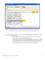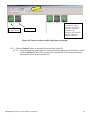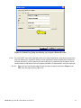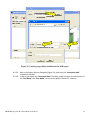
1
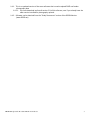
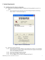
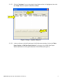
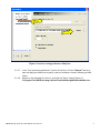
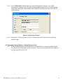
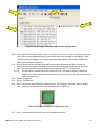
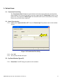
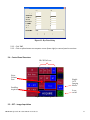
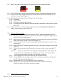
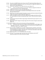
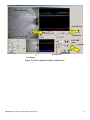
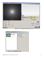
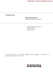
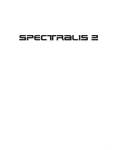
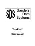
DRCR.NET Image Acquisition Protocol
Optical Coherence Tomography Using:
Heidelberg Spectralis OCT
1.
PROCEDURE SUMMARY FOR EXPERIENCED USERS ...................................................................................................................2
1.1.
1.2.
1.3.
1.4.
2.
ENSURE THAT YOUR HEIDELBERG SYSTEM MEETS SYSTEM REQUIREMENTS ............................................................................................... 2
ACQUIRE SD OCT SCAN/RESCAN(S) FOR STUDY EYE(S) PER PROTOCOL SPECIFICATION ............................................................................... 2
EXPORT SCAN DATA TO NEW EMPTY FOLDER NAMED WITH STUDY ID AND VISIT ....................................................................................... 2
UPLOAD DATA TO COORDINATING CENTER USING DRCR.NET IMAGE UPLOAD CLIENT SOFTWARE ............................................................... 2
SYSTEM REQUIREMENTS ..........................................................................................................................................................4
2.1.
2.2.
HEIDELBERG SPECTRALIS SOFTWARE CONFIGURATION ......................................................................................................................... 4
WINDOWS EXPLORER CONFIGURATION ............................................................................................................................................ 7
3.
SYSTEM START AND LOGIN ......................................................................................................................................................9
4.
ENTERING STUDY PATIENT DATA ........................................................................................................................................... 10
4.1.
4.2.
5.
PATIENT EXAM ....................................................................................................................................................................... 13
5.1.
5.2.
5.3.
5.4.
5.5.
5.6.
6.
EXAMINATION DATA DIALOG ........................................................................................................................................................ 13
DEVICE TYPE SELECTION .............................................................................................................................................................. 13
EYE DATA WINDOW (FIGURE 13) ................................................................................................................................................. 13
CONTROL PANEL OVERVIEW ........................................................................................................................................................ 14
OCT – IMAGE ACQUISITION......................................................................................................................................................... 14
OCT ACQUISITION PARAMETERS .................................................................................................................................................. 19
IMAGE EXPORT PROCEDURES ................................................................................................................................................ 20
6.1.
7.
CREATING NEW PATIENT RECORD ................................................................................................................................................. 10
MANAGING EXISTING PATIENTS – SETTING REFERENCE SCAN ............................................................................................................. 11
VISIT EXPORT STEPS ................................................................................................................................................................... 20
UPLOAD DATA ........................................................................................................................................................................ 29
DRCR NET Spectralis Procedure FINAL 10-10-10.doc
1
1. Procedure Summary for Experienced Users
1.1. Ensure that your Heidelberg system meets system requirements
1.1.1. See System Requirements (Section 2) for details on system configuration, minimum software
version, and required custom software.
1.2. Acquire SD OCT scan/rescan(s) for study eye(s) per protocol specification
1.2.1. Enter the following patient identifying information into the patient record: Last Name = DRCRProtocol (e.g. DRCR-O) and First Name = PT Study ID; Patient-ID = O039-0246AA.
1.2.2. To Obtain Baseline Scans:
1.2.2.1. Obtain pre-set Dense Volume Scan (20° x 20°). Scan configuration of 49 B-scan sections,
16 Frames OCT ART Mean, 120 um spacing, high speed (512 A scans/B scan).
1.2.2.2. Obtain pre-set 7 Line Raster Scan. Scan configuration of 30°x5°, 25 Frames OCT ART
Mean, 240 um spacing, high resolution.
1.2.2.3. Scan Qualify Factor > 25/40 decibels (db), if possible.
1.2.3. To Obtain Follow-up Scans/Repeat Scans:
1.2.3.1. Set baseline volume scan as the reference image (note: in a study with replicate scans the
initial scan will be set as the reference image).
1.2.3.2. Obtain the Dense Volume Scan from the pre-set options selecting ‘Follow-up’ from the
OCT Acquisition Window to use the baseline scan as reference (Scan configurations same
as 1.2.1.1).
1.2.3.3. Set baseline raster scan as the reference image.
1.2.3.4. Obtain pre-set 7 Line Raster Scan (Scan configurations same as 1.2.1.2).
1.2.3.5. Scan Qualify Factor > 25/40 decibels (db), if possible.
1.3. Export scan data to new empty folder named with Study ID and Visit
1.3.1. Example folder names include “J039-0246RU 14 week” and “O039-0246RU Heidelberg
Spectralis” for protocol “J” and “O”, respectively.
1.3.2. Patient’s Study ID (e.g. “J039-0246RU” or “O039-0246RU”) must be entered into the “PatientID” field of the patient record prior to export
1.3.3. For each scan or rescan acquired for the visit per protocol instructions, perform the following
two export steps:
1.3.3.1. Export scan as an E2E file. For the right eye name the volume scan OD1.E2E and name the
raster scan ODR.E2E (note: in a study with replicates scans the replicate volume scan will
be named OD2.E2E).
1.3.3.2. Export scan as an XML file (requires prior installation of DRCR.net Image Upload Client
software and related configuration steps; see System Requirements). Select the
corresponding E2E file to complete XML export.
1.3.4. Export process should produce two files per scan (.E2E and .XML) in the export folder
1.4. Upload data to Coordinating Center using DRCR.net Image Upload Client software
DRCR NET Spectralis Procedure FINAL 10-10-10.doc
2
1.4.1. This is an updated version of the same software that is used to upload DRCR.net fundus
photography data
1.4.1.1. You must download and install version 2.0 of this software, even if you already have the
older version installed for photography uploads.
1.4.2. Software can be obtained from the “Study Documents” section of the DRCR Web site
(www.DRCR.net)
DRCR NET Spectralis Procedure FINAL 10-10-10.doc
3
2. System Requirements
2.1. Heidelberg Spectralis software configuration
2.1.1. Ensure that your Heidelberg Eye Explorer’s HRA/Spectralis Viewing Module is version 5.1 or
higher
2.1.1.1. You can check your current software version by launching Eye Explorer and selecting
“Help >> About…” from the menu (Figure 1).
Figure 1: Software version information
2.1.2. XML Export module configuration
2.1.2.1. If not already done, install the DRCR.net Image Upload Client software on the Heidelberg
SD OCT machine; this installer includes a piece of software that supports the data export
process from Heidelberg Eye Explorer.
2.1.2.2. Launch the Heidelberg Eye Explorer software
2.1.2.3. Choose “Setup >> Options” from the menu
2.1.2.4. Click the “Plug Ins” tab in the Options dialog box (see Figure 2)
DRCR NET Spectralis Procedure FINAL 10-10-10.doc
4
2.1.2.5. Click the “hraviewer” entry in the plugin listing listbox so that it is highlighted, then click
the “Setup” button to open a Preferences window
2.1.2.4
2.1.2.5
2.1.2.5
Figure 2: Setup >> Options dialog box
2.1.2.6. In the tree shown in the left-hand pane of the Preferences window, click on the “Data
Export Options >> XML Data Export Options” to bring up a list of XML Data Export
Options preferences in the right-hand pane of the window (see Figure 3)
DRCR NET Spectralis Procedure FINAL 10-10-10.doc
5
2.1.2.6
2.1.2.8
Figure 3: hraviewer setup preferences dialog box
2.1.2.7. In the “Post-processing application” section of the form, click the “Browse” button to
open a dialog that allows you to specify a piece of software to launch following an XML
export
2.1.2.8. Browse to the following file, select it, and click the “Open” button (Figure 4):
C:\Program Files\DRCR.net Image Upload Client\HeidelbergXMLExportHandler.exe
DRCR NET Spectralis Procedure FINAL 10-10-10.doc
6
2.1.2.8
Figure 4: Browsing to the HeidelbergXMLExportHandler.exe file
2.1.2.9. Click the “OK” button to close the Preferences window
2.1.2.10. Click the “OK” button to close the Options window
2.2. Windows Explorer Configuration
2.2.1. Make sure that Windows Explorer is NOT set to “Hide extensions for known file types”. Follow
the steps below if you are unsure how to do this.
2.2.1.1. Double-click on the “My Computer” icon to open the Windows Explorer window
2.2.1.2. In the Windows Explorer window, choose “Tools >> Folder Options…” from the menu (see
Figure 5)
DRCR NET Spectralis Procedure FINAL 10-10-10.doc
7
2.2.1.2
Figure 5: Accessing the Tools >> Folder Options dialog box from a Windows Explorer window
2.2.1.3. In the “Folder Options” dialog box, click the “View” tab (see Figure 6)
2.2.1.4. Under the “Advanced settings” tree, uncheck the checkbox next to “Hide extensions for
known file types”
2.2.1.5. Then click the OK button.
DRCR NET Spectralis Procedure FINAL 10-10-10.doc
8
2.2.1.3
2.2.1.4
Figure 6: Unchecking the "Hide extensions" checkbox
3. System Start and Login
Please refer to the user manual for your Heidelberg system to turn on the hardware and launch the supporting
software to reach the database screen shown in Figure 7:
DRCR NET Spectralis Procedure FINAL 10-10-10.doc
9
Figure 7: Main database screen in Eye Explorer software
On the left side, all patients in the database are listed. The right window serves to select patients for
new examinations and review or for batch processing (e.g. export). Note: depending on the software
version, some of the titles corresponding to the icons may be slightly different. Double click on a
patient name to move the file to the right window. Please note that closing the window will shut down
the program.
4. Entering Study Patient Data
If this is the baseline scan for a new patient, follow the directions in section 4.1 to create a new patient record.
Then skip to section 5 for the directions on acquiring patient images. If this is a follow-up scan, then go to
section 4.2 to learn how to set a reference scan and then to section 5 for directions on acquiring patient
images.
4.1. Creating New Patient Record
4.1.1. If this is the baseline scan for a new patient, you will need to create a new patient record. To
do so, click on the “New Patient” button (Figure 8).
4.1.1
Figure 8: Creating a new patient record
DRCR NET Spectralis Procedure FINAL 10-10-10.doc
10
4.1.2. In the “Patient Data” window (Figure 9), enter the following information: Last = DRCR(Protocol) (e.g. DRCR-J); First = PT Study ID (J039-0246RU); Date of birth = 1/1/1900; Gender
(sex) = Male; Patient-ID = J039-0246RU. Other fields do not need to be filled in for DRCR.net
study purposes.
Figure 9: Patient Data Window
4.1.3. Skip section 4.2 and go directly to section 5 (Patient Exam) for the directions on acquiring
patient images
4.2. Managing Existing Patients – Setting Reference Scan
4.2.1. To open an existing patient file to complete a new examination, in the patient listbox (Figure
10), double-click on the patient to be scanned (4.2.1.a) so that the patient identifier appears in
the right-hand list box (4.2.1.b)
DRCR NET Spectralis Procedure FINAL 10-10-10.doc
11
4.2.1
4.2.7
4.2.1.b
4.2.1.a
Figure 10: Performing a new examination on an existing patient
4.2.2. In the right-hand list box, double-click on the subject entry (4.2.1.b) and a new screen will open
that shows pictorial representations of the various scan sets available for the subject. These
representations will appear on 1 or more date tabs depending on the number of dates that
that prior studies were obtained.
4.2.3. Select the tab that has the date the baseline scans were obtained and Right click on the
baseline scan to set it as the reference scan (note: in a study with repeat scans on the same
date the initial scan will be set as the reference image for the 2nd or repeat scan).
4.2.3.1. Set the baseline volume scan as the reference if you are about to acquire a follow-up
volume scan or set the baseline raster scan as the reference if you are about to acquire a
follow-up raster scan.
4.2.4. Select “Progression”
4.2.5. Select “Set Reference”
4.2.6. Scan has now been selected as the reference scan. This setting is confirmed when a red Ref
icon appears on the bottom left corner of baseline scan (Figure 11)
Figure 11: Baseline Image Set as Reference Scan
4.2.7. Click on the database button to return to the database screen.
DRCR NET Spectralis Procedure FINAL 10-10-10.doc
12
5. Patient Exam
5.1. Examination Data dialog
The “Examination Data” dialog box opens before each exam (upon submission of the patient
data window), but can also be opened at any later stage using the “Examination” button in the
patient file. The respective “Device Type” for the examination must be selected from the dropdown menu; all other data is optional.
5.2. Device Type selection
5.2.1. Please select “Spectralis HRA + OCT” from the “Device Type” drop-down menu in the window
below.
5.2.1
Figure 12: Examination Data dialog
5.2.2. Click “OK”
5.2.3. The Eye Data Window will open.
5.3. Eye Data Window (Figure 13)
5.3.1. Please Note: Do NOT change any data into this window.
DRCR NET Spectralis Procedure FINAL 10-10-10.doc
13
Figure 13: Eye Data dialog
5.3.2. Click “OK”
5.3.3. Click on yellow button on computer screen (lower right) or control panel to continue
5.4. Control Panel Overview
IR / ICGA Laser
Intensity
Select
Volume
Scan
Enable
OCT
Imaging
Modes
Start/Stop
Acquisition
Laser
on/off
Figure 14: Control panel
5.5. OCT – Image Acquisition
DRCR NET Spectralis Procedure FINAL 10-10-10.doc
14
5.5.1. Wait for the Laser On/Off button on the Control Panel to turn from Red to Yellow.
5.5.2. On the Control Panel, Inactive/unselected buttons are Red; Active/Selected buttons are Blue.
5.5.3. Press the Yellow Laser On/Off button on the Control Panel to activate the Laser/OCT. It will
turn green once activated (Figure 14)
5.5.4. Make sure that the following items in figure 14 are selected blue:
5.5.4.1. OCT button
5.5.4.2. Volume button
5.5.4.3. Field button should be at 30 degrees
5.5.4.4. IR Intensity button will default to 100% but should be adjusted for patient media, typically
50% - 75%
5.5.5. Finally, select the IR + OCT button (blue) (Figure 14), then the OCT Acquisition Window will
appear on the computer screen (Figure 15)
5.5.6. To Acquire Baseline Images:
5.5.6.1. First select the DENSE button under Preset in the OCT Acquisition Window (Figure 15)
5.5.6.2. Confirm the default parameters are set for the selected scan configuration (Figure 15, see
section 5.6 for scan configuration)
5.5.6.3. Align/center the camera head with the patient’s eye using the black and white (IR) fundus
image on the upper left side of the monitor (Figure 15).
5.5.6.4. Focus the black and white fundus image using the black knob facing the operator on the
camera head
5.5.6.5. Align/center the OCT Image on the upper right side of the monitor using the camera head
(Figure 15).
5.5.6.6. Press the Acquire button (blue) (Figure 14) on the control panel to start acquiring OCT
scans.
5.5.6.6.1.
Please note that the live scan images are always displayed as small image in the
lower part of the screen (Figure 15). Top images are not live, as the eye moves the
quality can be adjusted by referring to the live images on bottom
5.5.6.7. Upon completion of the scan the instrument will stop automatically.
5.5.6.8. Once the DENSE Scan is complete, select the 7 Lines (raster scan) button under Preset in
the OCT Acquisition Window (Figure 16).
5.5.6.9. Repeat steps 5.5.6.2 – 5.5.6.7 above for the 7Line Raster Scan.
5.5.6.10. Click the “X” on the upper right hand side of the active window to exit the OCT
Acquisition Window and to save the acquired images.
5.5.7. To Acquire Follow-up/Repeat Images:
DRCR NET Spectralis Procedure FINAL 10-10-10.doc
15
5.5.7.1. First select the DENSE button under Preset in the OCT Acquisition Window (Figure 15)
5.5.7.2. Confirm the default parameters are set for the selected scan configuration (Figure 15, see
section 5.6 for scan configuration)
5.5.7.3. Select Follow-up Button on the right side of the screen (Figure 15).
5.5.7.3.1.
Note: if the Follow-up button is gray then a reference image has not been set.
Please see section 4.2 to set a reference image
5.5.7.4. Double click on the scan to use as the reference (Figure 17)
5.5.7.5. At this time, the small images at the bottom of the window will show the scans taken
during the baseline exam.
5.5.7.6. Align/center the camera head with the patient’s eye using the black and white (IR) fundus
image on the upper left side of the monitor (Figure 15).
5.5.7.7. A green box appears around the IR fundus image and OCT image once the frame of the
live image matches the frame of the baseline exam. The OCT scan line will turn from red
to blue.
5.5.7.8. Focus the black and white fundus image using the black knob facing the operator on the
camera head
5.5.7.9. Align/center the OCT Image on the upper right side of the monitor using the camera head
(Figure 15).
5.5.7.10. Upon completion of the scan the instrument will stop automatically.
5.5.7.10.1.
Please note that the live scan images are always displayed as small images in the
lower part of the screen. Top images are not live, as the eye moves the quality can be
adjusted by using live scan images on bottom
5.5.7.11. Once the follow-up DENSE Scan is complete, follow the steps in section 4.2 to reset the
reference image to the baseline raster scan. Then follow the steps in section 5 to return
to the OCT Acquisition window. Now select the 7 Lines (raster scan) button under Preset
in the OCT Acquisition Window (Figure 16).
5.5.7.12. Repeat steps 5.5.7.2 – 5.5.7.10 above for the 7Line image.
5.5.7.13. Click the “X” on the upper right hand side of the active window to exit the OCT
Acquisition Window and to save the acquired images.
DRCR NET Spectralis Procedure FINAL 10-10-10.doc
16
Fundus (IR) Image
Dense Preset
5.5.7.3
5.5.6.1
Quality Bar
OCT ART
mean
Sections
5.5.6.2
Live Image
Scan Details
Length
Figure 15: OCT Acquisition window (Volume Scan)
DRCR NET Spectralis Procedure FINAL 10-10-10.doc
17
5.5.6.8
Figure 16: OCT Acquisition window (Raster Scan)
Figure 17: Selecting Reference Scan
DRCR NET Spectralis Procedure FINAL 10-10-10.doc
18
5.6. OCT Acquisition Parameters
5.6.1. The following parameters represent the configuration for the preset DENSE volume scan
pattern.
Scan Extent: Volume Scan (20° x 20°) as indicated above the “Sections” information.
Scan Sections: (B-scans): 49 sections (120 microns spacing).
OCT ART Mean: 16 Frames.
Quality Bar: indicates the minimum allowable image quality. Range is 0 - 40, the higher
number the higher the quality. A reasonable range for minimum quality is 25 decibels or
more.
5.6.1.5. Eye Length: M (medium). If you cannot focus at this setting, then adjust by changing the
Eye Length from its default of M (medium) to L (long) or XL (extra long) or S (short) until
you can focus that retina.
5.6.1.1.
5.6.1.2.
5.6.1.3.
5.6.1.4.
5.6.2. The following parameters represent the configuration for the preset 7Line raster scan.
Scan Extent: Volume Scan (30° x 5°) as indicated above the “Sections” information.
Scan Sections: (B-scans): 7 sections (240 microns spacing).
OCT ART Mean: 25 Frames.
Quality Bar: indicates the minimum allowable image quality. Range is 0 - 40, the higher
number the higher the quality. A reasonable range for minimum quality is 25 decibels or
more.
5.6.2.5. Eye Length: M (medium). If you cannot focus at this setting, then adjust by changing the
Eye Length from its default of M (medium) to L (long) or XL (extra long) or S (short) until
you can focus that retina.
5.6.2.1.
5.6.2.2.
5.6.2.3.
5.6.2.4.
DRCR NET Spectralis Procedure FINAL 10-10-10.doc
19
6. Image Export Procedures
6.1. Visit Export Steps
6.1.1. Your target export file system may be fixed media (C: drive, network drive, etc.) or removable
media (CDs, DVDs, USB devices). If you are exporting to removable media, insert the media
into its port.
6.1.2. Create a new folder on the export file system (see Figure 18) to contain all the exported data
for a single patient visit, including data for both eyes (if required by protocol) and rescan data
(if required by protocol).
6.1.3. Name the new folder using the patient’s Study ID code and visit name; for example:
6.1.3.1. “J039-0246RU 14 week” for a 14 week follow-up visit in protocol J (Figure 18)
6.1.3.2. “O039-0246RU Zeiss Cirrus” or “O039-0246RU Heidelberg Spectralis” for one of the
machine-specific visits in Protocol O
Figure 18: Example export folder on local)(C:) drive
6.1.4. Launch the Heidelberg EyeExplorer software (see Figure 19)
6.1.5. In the patient listbox, double-click on the patient whose data you want to export so that the
patient appears over in the right-hand list box
DRCR NET Spectralis Procedure FINAL 10-10-10.doc
20
6.1.5
6.1.5
Figure 19: Eye Explorer main screen with selected patient displaying in right-hand pane
In the right-hand list box, double-click on the subject entry and a new screen will open (see Figure
6.1.6. Figure 20) that shows pictorial representations of the various scan sets available for the subject
6.1.6.1. This example shows a
• Baseline right eye (OD) scan with the volume scan and raster scan where the
volume scan is set as the reference image (red box).
• Left eye (OS) scans from a protocol with repeat images at the same visit. Includes
the first volume scan set as the reference image (red box), a raster scan, and the
second volume scan not set as reference but rather as the follow-up scan that is
being compared to the reference scan (grey hatched sandwiched box).
DRCR NET Spectralis Procedure FINAL 10-10-10.doc
21
6.1.7
Volume Scan
(Reference Scan)
Raster Scan
Volume Scan
(Not reference, rather a
follow-up scan (replicate
performed on the same
day) that is being
compared to the reference
scan (the original scan
obtained on this date)
Figure 20: Patient scan data window displaying scan listings
6.1.7. Click the “Patient” button at the top of the screen (see Figure 20)
6.1.7.1. In the resulting form (see Figure21), make sure that the appropriate Pt ID value is entered
into the “Patient-ID” field. If the correct value is already there, click Cancel; otherwise,
enter the correct Pt ID value and click OK.
DRCR NET Spectralis Procedure FINAL 10-10-10.doc
22
6.1.7.1
Figure 21: Patient Data dialog box allowing user to input a Patient ID value
6.1.8. For each IR/OCT scan to be exported, perform the steps listed below. Note that a patient with
only one study eye in a protocol with no rescan requirement would involve two scan exports
(volume and raster), while a patient with two study eyes in a protocol that includes a rescan
would involve six iterations of this scan export procedure (2 volume and 1 raster for each eye).
6.1.8.1. Right-click the icon representing the scan you want to export and select “Export >> as
E2E” from the pop-up menu (Figure 22)
DRCR NET Spectralis Procedure FINAL 10-10-10.doc
23
6.1.8.1
Figure 22: Right-clicking on a scan and selecting Export >> as E2E
6.1.8.2. When the export dialog box appears, perform the following steps (see Figure 23):
Click the “Browse” button and browse to the empty folder you created earlier as
6.1.8.2.1.
your destination for export.
6.1.8.2.2.
Instead of the default filename that appears in the “File name” box, enter the
following filename instead:
• “OD1.E2E” for the right eye volume scan
• “ODR.E2E” for the right eye raster scan
• If the protocol requires a repeat scan: “OD2.E2E” for the right eye repeat volume
scan
• “OS1.E2E” for the left eye volume scan
• “OSR.E2E” for the left eye raster scan
• If the protocol requires a repeat scan: “OS2.E2E” for the left eye repeat volume scan
6.1.8.2.3.
Click the “Save” button
DRCR NET Spectralis Procedure FINAL 10-10-10.doc
24
6.1.8.2.1
6.1.8.2.2
6.1.8.2.3
Figure 23: Choosing target folder and filename for E2E export
6.1.8.3. Back in the Export Options dialog box (Figure 24), make sure the “Anonymize data”
checkbox is checked
6.1.8.4. In the section below the “Anonymize data” checkbox, make sure that the radio buttons in
the “Last Name” and “First Name” are set to the default “Patient-ID” selection
DRCR NET Spectralis Procedure FINAL 10-10-10.doc
25
6.1.8.3
6.1.8.4
6.1.8.4
Figure 24: Choosing export options for E2E export
6.1.8.5. Click the “OK” button and the raw data will be exported to your target folder
6.1.8.6. Back on the Eye Explorer screen that displays the various scans available for your patient,
right-click the same scan that you just exported and select “Export >> as XML” (see Figure
25)
DRCR NET Spectralis Procedure FINAL 10-10-10.doc
26
6.1.8.6
Figure 25: Right-clicking on a scan and selecting Export >> as XML
6.1.8.6.1.
If necessary, wait for the “Exporting Data to XML. Please wait.” dialog box to
disappear
6.1.8.6.2.
A window entitled DRCR.net XLM window export custom DRCR.net window
should appear and prompt you to select an exported E2E file that matches the XML
being exported (see Figure 26)
Navigate to the E2E file that you just exported for this scan, select that file, click
6.1.8.6.3.
the “Open” button, and an XML data file will be created alongside the E2E file that you
previously exported
DRCR NET Spectralis Procedure FINAL 10-10-10.doc
27
6.1.8.6.3
Figure 26: Dialog box in XML export asking you to choose the E2E file associated with the XML export
6.1.8.6.4.
Following the XML export, you should be able to see a matched pair of files with
the same basename in your export folder (see Figure 28)
6.1.8.6.4.1.
If the error message in Figure 27: Error exporting XML file (below)
appears, please check your current directory and navigate to the correct folder
where the E2E files were exported to.
Figure 27: Error exporting XML file
DRCR NET Spectralis Procedure FINAL 10-10-10.doc
28
6.1.8.6.4
Figure 28: Results of exporting one scan to an E2E file, then exporting again as XML, as seen in
Windows Explorer (Example of OS Eye with Repeat Image)
6.1.9. Repeat the entire export process for the raster image as well as the fellow eye, if required by
protocol, and for rescan data for one or both eyes, if required by protocol
7. Upload Data
You will use the DRCR.net Image Upload application to upload your exported SD OCT study data. This is an
updated version of the same software that your site may have previously used to upload large digital image
files associated with Photography or Fluorescein Angiogram visits.
Please obtain the user manual and the installation software for version 2.0 of this software application under
the “Study Documents” section of the DRCR Web site (www.DRCR.net).
DRCR NET Spectralis Procedure FINAL 10-10-10.doc
29