1
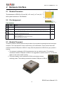
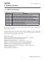
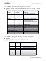
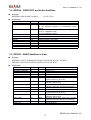
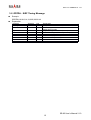
SR-92 Manual V1.0
GPS Engine Board Manual
SR-92
SIRF STAR Ⅲ
V 1.0
Easy to Use Ultra-High Performance
GPS Smart Antenna Module
With Power Control
Made in Taiwan
2008/08/08
[email protected]
www.dagamagps.com
FREE SERVICE HOT-LINE(FOR MAINLAND):400-820-1322
SR-92 Manual V1.0
Contents
1
2
3
Specifications subject to
change without prior notice!
Introduction ……….………………………………………………………………..... 1
1.1
1.2
OVERVIEW............................................................................................................ 1
MAIN FEATURES................................................................................................... 1
1.3
1.4
1.5
RECEIVER SPECIFICATIONS...................................................................................2
PROTOCOLS.......................................................................................................... 3
ANTENNA............................................................................................................. 3
Hardware Interface ………………………………………………………………..... 4
2.1
2.2
MODULE DIMENSION........................................................................................... 4
PIN ASSIGNMENT.................................................................................................. 4
2.3
2.4
2.4.1
MODULE PLACEMENT.......................................................................................... 4
POWER SAVING.....................................................................................................5
Power Saving of Trickle Power............................................................................5
2.4.2
2.4.3
2.4.4
Power Saving of Adaptive Trickle Power............................................................ 5
Power Saving of Push To Fix............................................................................... 5
Power Saving of Power Switch............................................................................ 6
Software Interface ………………………….......………………………………………7
3.1
3.2
NMEA OUTPUT MESSAGES................................................................................. 7
GPGGA - GLOBAL POSITIONING SYSTEM FIX DATA...........................................8
3.3
3.4
3.5
3.6
GPGLL - GEOGRAPHIC POSITION - LATITUDE / LONGITUDE............................... 8
GPGSA - GNSS DOP AND ACTIVE SATELLITES..................................................9
GPGSV - GNSS SATELLITES IN VIEW................................................................. 9
GPRMC - RECOMMENDED MINIMUM SPECIFIC GNSS DATA............................ 10
3.7
3.8
GPVTG - COURSE OVER GROUND AND GROUND SPEED................................... 10
GPZDA - SIRF TIMING MESSAGE..................................................................... 11
4
Electrical and Environmental Data ……………………………………………...…. 12
5
Application …………………………………………………………………………..... 13
SR-92 User’s Manual V1.0
1
SR-92 Manual V1.0
1 Introduction
1.1
Overview
SR-92 is a low-power, ultra-high performance, easy to use GPS smart antenna module based on
SiRF’s third generation single chip. Its low power consumption and high performance enables the
adoption of handheld applications. The slim design allows SR-92 to be placed on topside of the
housing to have best GPS signal reception. The 5-pin I/O interface is then connected to the main
board with either connector or wire soldering.
The integrated antenna design helps reduce the RF and EMI issues to minimum. Fast adoption and
high yield production becomes possible.
The power control feature is very convenient to turn on/off power via GPIO control pin. It’s
especially useful in cases such as to turn off power as the user just wants to watch a movie and
GPS function is not needed in the PMP case.
1.2
Main Features
Not only handheld but also any other GPS applications can share the following major features of
SR-92.
Easy adoption with best performance
Integrated antenna and EMC protection
Built-in backup battery allowing hot/warm starts and better performance
No external component demand, just connect and use.
Minimum RF and EMI efforts
Small size of 18 (W) x 21 (L) x 7 (H) (mm) with patch antenna of 18x18x4mm.
Fully implementation of ultra-high performance SiRF StarⅢ single chip architecture
High tracking sensitivity of -159dBm
Low power consumption of 40mA at full tracking
Hardware power saving control pin allowing power off GPS via GPIO
SR-92 could be arranged at best reception location inside housing
Firmware upgradeable for future potential performance enhancements
SR-92 User’s Manual V1.0
1
SR-92 Manual V1.0
1.3
Receiver Specifications
Features
Specifications
GPS receiver type
Horizontal Position Accuracy
20 channels, L1 frequency, C/A code
< 2.5m (Autonomous)
< 2.0m (WAAS)
(50% 24hr static, -130dBm)
Velocity Accuracy
<0.01 m/s (speed)
<0.01° (heading)
(50%@30m/s)
Time accuracy
1µs or less
TTFF (Time to First Fix)
Hot Start: 1s
(50%, -130dBm, autonomous)
Warm Start: 35s
Cold Start: 42s
Sensitivity
Tracking: –159dBm
(Autonomous)
Acquisition: -142dBm
Measurement data output
Update time: 1 second
NMEA output protocol: V.3.00
Baud rate: 4800 (default), 9600, 19200, 38400, 57600
bps (8-N-1)
Datum: WGS-84
Default: GGA, GSA, RMC, and GSV
Max. Altitude
Other options: VTG, GLL, ZDA, or SiRF binary
<18,000 m
Max. Velocity
<1,852 km/hr
SBAS Support
WAAS, EGNOS
Dynamics
<4g
Power consumption
40mA, continuous tracking mode
Power supply
3.3V
Dimension (single side)
18 (W) x 21 (L) x 7 (H) mm w/ 18x18x4 (mm) patch antenna
Operating temperature
-40°C ~ +85°C
Storage temperature
-40°C ~ +125°C
SR-92 User’s Manual V1.0
2
SR-92 Manual V1.0
1.4
Protocols
Both NMEA and SiRF binary protocols could be supported via serial UART I/O port – RXA/TXA.
The default supported protocol is NMEA protocol.
1. Serial communication channel
i.
No parity, 8-data bit, 1-stop bit (N-8-1)
ii.
User selectable factory set baudrate among 4800, 9600, 19200, 38400, and
57600 (default 4800) bps.
2. NMEA 0183 Version 3.00 ASCII output
1.5
i.
Default GGA (1 sec), GSA (1 sec), GSV (3 sec), RMC (1 sec)
ii.
Optional VTG, GLL, ZDA
Antenna
SR-92 has a built-in patch antenna of dimension 18x18x4mm.
To have the best performance, we suggest tuning the RF antenna together with product’s outside
shell of housing.
SR-92 User’s Manual V1.0
3
SR-92 Manual V1.0
2 Hardware Interface
2.1
Module Dimension
The dimension of SR-92 is 18 mm (W) x 21 mm (L) x 7 mm (H)
with a patch antenna of 18x18x4mm.
2.2
Pin Assignment
4
5-pin Interface
Pin
1
Name
GND
2
VCC
3
TX
Port A serial data output (GPS out); N-8-1, NMEA v3.00 output
4
RX
Port A serial data input (GPS in); N-8-1, accepts commands from external applications, e.g.
SiRFDemo.
Input
5
PWR_CTRL
Hardware controlled power saving pin.
If this function is used, it is usually connected to a GPIO pin of a micro-processor.
“Low”: for normal run
“High” or floating: turn off VCC for power saving
Tie it to low if this pin is not used.
Input
2.3
Ground
Function
I/O
Input
Power supply of 3.3 ~ 5.5 VDC
Input
Output
Module Placement
The SR-92 module could be placed on any location of your product’s housing that has best signal
reception. The 5-pin interface is then connected to your motherboard. There are two items that
extrude the bottom PCB plane of SR-92. It may affect the placement of SR-92 into your product’s
housing.
1. The antenna is soldered to SR-92 at the bottom via one soldering point. The soldering
extrudes the bottom PCB plane of SR-92. It is suggested to reserve a hole of ϕ = 2 mm and
depth of 1mm on the under housing.
2. The built-in battery is also soldered to SR-92 at the bottom via two
soldering points. The soldering extrudes the bottom PCB plane of SR-92.
SR-92 User’s Manual V1.0
4
SR-92 Manual V1.0
2.4
Power Saving
SR-92 supports various kinds of power saving mechanisms – Trickle Power, Adaptive
Trickle Power, Push To Fix, and power switch. The first three kinds of power saving
mechanisms are implemented in software and the power switch mechanism is
implemented in hardware.
2.4.1 Power Saving of Trickle Power
The trickle power saving mechanism is achieved by switching off and on CPU and RF at a
fixed time interval. The biggest time interval to report a position is 10 seconds. The on and
off ratio is configurable. This feature is useful for applications that need to report position
regularly while power saving is significant. This feature is done by firmware automatically if
this feature is enabled. The standard firmware does not turn on this feature. It could be
customized by request of MOQ.
2.4.2 Power Saving of Adaptive Trickle Power
The adaptive trickle power saving mechanism is basically the same as trickle power saving
mechanism with difference that it would not turn the power off if the signal quality is not
good enough for tracking. Thus, it keeps both benefits of performance and power saving
intelligently. This feature is done by firmware automatically if this feature is enabled. The
standard firmware does not turn on this feature. It could be customized by request of MOQ.
2.4.3
Power Saving of Push To Fix
The Push To Fix power saving mechanism will not report position data until a specified time
interval expires or triggered by external event. Typically, to keep the up to date position
data, it would wake up to collect ephemeris and almanac data every 30 minutes. The time
interval is also configurable. This mechanism is especially useful for applications that need
position data only on demand. This feature is done by firmware automatically if this feature
is enabled. The standard firmware does not turn on this feature. It could be customized by
request of MOQ.
SR-92 User’s Manual V1.0
5
SR-92 Manual V1.0
2.4.4
Power Saving of Power Switch
The Power Switch power saving mechanism will turn off not only the CPU and RF but also
the whole engine board. In the mean time, the backup battery will start to power GPS’s
RTC and internal memory for better performance.
The power saving is controlled by the external application via the control pin (PWR_CTRL;
pin 5). The engine board will be on if PWR_CTRL pin is low. It would be off if the pin is high
or floating. The designer has full control of the power supply status of the smart antenna.
The power saving is also more complete. Applications such as PMP navigator may prefer
to stop GPS while it just runs movie watching. There might be similar demand for different
applications. This mechanism is achieved by hardware and external control of pin
PWR_CTRL is required if this mechanism is used. Tie this pin to low if the mechanism is
not used.
SR-92 User’s Manual V1.0
6
SR-92 Manual V1.0
3 Software Interface
3.1 NMEA Output Messages
The NMEA-0183 Output Messages are shown as below:
NMEA Record
Descriptions
GPGGA
Global positioning system fixed data: time, position, fixed type
GPGLL
Geographic position: latitude, longitude, UTC time of position fix and status
GPGSA
GPS receiver operating mode, active satellites, and DOP values
GPGSV
GNSS satellites in view: ID number, elevation, azimuth, and SNR values
GPRMC
Recommended minimum specific GNSS data: time, date, position, course, speed
GPVTG
Course over ground and ground speed
GPZDA
PPS timing message (synchronized to PPS)
The SR-92 adopts interface protocol of National Marine Electronics Association's NMEA-0183 Version 3.00
interface specification. SR-92 supports 7 types of NMEA sentences (GPGGA, GPGLL, GPGSA, GPGSV,
GPRMC, GPVTG, and GPZDA).
The default output sentences are GPGGA, GPGSA, GPGSV, and GPRMC. The UART communication
parameters are 4800 bps, 8 data bits, 1 stop bit, and no parity. Other output sentences, baud rate, and
related configurations could be requested based on MOQ.
Single message example
$GPGGA,101229.487,3723.2475,N,12158.3416,W,1,07,1.0,9.0,M, , , ,0000*3E
$GPGLL,2446.8619,N,12100.2579,E,060725.000,A,A*7E
$GPGSA,A,3,05,02,26,27,09,04,15, , , , , ,1.8,1.0,1.5*11
$GPGSV,3,1,12,07,62,081,37,16,61,333,37,01,60,166,37,25,56,053,36*74
$GPGSV,3,2,12,03,43,123,33,23,32,316,34,14,17,152,30,20,16,263,33*78
$GPGSV,3,3,12,19,17,210,29,06,08,040,,15,06,117,27,21,05,092,27*7E
$ GPRMC,151229.487,A,3723.2475,N,12148.3416,W,0.13,309.62,120598,,,A*5F
$GPVTG,,T,,M,0.00,N,0.0,K,A*13
$GPZDA,060526.000,20,06,2006,,*51
SR-92 User’s Manual V1.0
7
SR-92 Manual V1.0
3.2 GPGGA - Global Positioning System Fix Data
Example
Explanation
$GPGGA,101229.487,3723.2475,N,12158.3416,W,1,07,1.0,9.0,M, , , ,0000*3E
Contents
Message ID
UTC Time
Example
$GPGGA
101229.487
Latitude
3723.2475
North/South
Longitude
N
12158.3416
East/West
Position Fix Indicator
W
1
Satellites Used
07
HDOP
MSL Altitude
Unit
Geoidal separation
Units
Age of Diff. Corr.
Diff. Ref. Station ID
checksum
<CR><LF>
1.0
9.0
M
Unit
Explanation
GGA protocol header
hhmmss.sss
hh: hour, mm: minute, ss: second
ddmm.mmmm
dd: degree, mm.mmmm: minute
N: North Latitude, S: South Latitude
dddmm.mmmm
dd: degree, mm.mmmm: minute
E: East Longitude, W: West Longitude
0: Fix not available or invalid,
1: GPS SPS Mode, fix valid,
2: Differential GPS, SPS Mode, fix valid,
3~5: Not supported,
6: Dead Reckoning Mode, fix valid
Number of satellites used in positioning
calculation (0 to 12)
Horizontal Dilution of Precision
meters
Meters
meters
M
Meters
Null fields when DGPS is not used
second
0000
*3E
End of sentence
3.3 GPGLL - Geographic Position - Latitude / Longitude
Example
$ GPGLL,2446.8619,N,12100.2579,E,060725.000,A,A*7E
Explanation
Contents
Message ID
Latitude
North/South
Longitude
East/West
UTC Time
Status
Mode Indicator
checksum
<CR><LF>
Example
$GPGLL
2446.8619
N
12100.2579
E
060725.000
A
A
*7E
Unit
Explanation
GLL protocol header
ddmm.mmmm
dd: degree, mm.mmmm: minute
N: North Latitude, S: South Latitude
dddmm.mmmm
dd: degree, mm.mmmm: minute
E: East Longitude, W: West Longitude
hhmmss.sss
hh: hour, mm: minute, ss: second
A: Data valid, V: Data invalid
A: Autonomous, D: DGPS, E: DR
End of sentence
SR-92 User’s Manual V1.0
8
SR-92 Manual V1.0
3.4 GPGSA - GNSS DOP and Active Satellites
Example
$GPGSA,A,3,05,02,26,27,09,04,15, , , , , ,1.8,1.0,1.5*11
Explanation
Contents
Message ID
Mode 1
Example
$GPGSA
A
Mode 2
3
Satellite used in solution
Satellite used in solution
…
PDOP
HDOP
VDOP
checksum
<CR><LF>
05
02
1.8
1.0
1.5
*11
Explanation
GSA protocol header
M: Manual—forced to operate in 2D or 3D mode
A: 2D Automatic—allowed to automatically switch
2D/3D
1: Fix not available
2: 2D (< 4 Satellites used)
3: 3D (> 3 Satellite s used)
Satellite on Channel 1
Satellite on Channel 2
Display of quantity used (12 max)
Position Dilution of Precision
Horizontal Dilution of Precision
Vertical Dilution of Precision
End of sentence
3.5 GPGSV - GNSS Satellites in View
Example
$GPGSV,2,1,07,07,79,048,42,02,51,062,43,26,36,256,42,27,27,138,42*71
$GPGSV,2,2,07,09,23,313,42,04,19,159,41,15,12,041,42*41
Explanation
Contents
Message ID
Number of messages
Message number
Satellites in view
Satellite ID number
Elevation
Example
$GPGSV
2
1
07
07
79
Unit
Azimuth
048
degrees
SNR (C/No)
42
dBHz
…
Satellite ID number
Elevation
27
27
degrees
Azimuth
138
degrees
SNR (C/No)
42
dBHz
checksum
<CR><LF>
*71
Explanation
GSV protocol header
Range 1 to 3
Range 1 to 3
Number of satellites visible from receiver
Channel 1 (Range 1 to 32)
Elevation angle of satellite as seen from
receiver channel 1 (00 to 90)
Satellite azimuth as seen from receiver
channel 1 (000 to 359)
Received signal level C/No from receiver
channel 1 (00 to 99, null when not tracking)
degrees
Channel 4 (Range 1 to 32)
Elevation angle of satellite as seen from
receiver channel 4 (00 to 90)
Satellite azimuth as seen from receiver
channel 4 (000 to 359)
Received signal level C/No from receiver
channel 4 (00 to 99, null when not tracking)
End of sentence
SR-92 User’s Manual V1.0
9
SR-92 Manual V1.0
3.6 GPRMC - Recommended Minimum Specific GNSS Data
Example
$GPRMC,151229.487,A,3723.2475,N,12148.3416,W,0.13,309.62,120598,,,A*5F
Explanation
Contents
Message ID
UTC Time
Example
$GPRMC
151229.487
Status
Latitude
A
3723.2475
North/South
Longitude
N
12148.3416
East/West
Speed over ground
Course over ground
W
0.13
309.62
Date
120598
Magnetic variation
Mode Indicator
checksum
Unit
knots
degrees
degrees
A
*5F
<CR><LF>
Explanation
RMC protocol header
hhmmss.sss
hh: hour, mm: minute, ss: second
A: Data valid, V: Data invalid
ddmm.mmmm
dd: degree, mm.mmmm: minute
N: North Latitude, S: South Latitude
dddmm.mmmm
dd: degree, mm.mmmm: minute
E: East Longitude, W: West Longitude
Receiver’s speed
Receiver’s direction of travel
Moving clockwise starting at due north
ddmmyy
dd: Day, mm: Month, yy: Year
This receiver does not support magnetic
declination. All “course over ground” data are
geodetic WGS84 directions.
A: Autonomous, D: D-GPS, N: Data not valid
A: Autonomous
M: Manual
D: DGPS
S: Simulation
E: Dead Reckoning
N: Data Invalid
End of sentence
3.7 GPVTG - Course over Ground and Ground Speed
Example
$GPVTG,309.62,T,,M,0.18,N,0.5,K,A*0F
Explanation
Contents
Message ID
Course over ground
Example
$GPVTG
309.62
Reference
Course over ground
Reference
Speed over ground
Unit
Speed over ground
Unit
Mode Indicator
T
Unit
degrees
degrees
M
0.18
N
0.5
K
A
knots
km/hr
Explanation
VTG protocol header
Receiver’s direction of travel
Moving clockwise starting at due north
(geodetic WGS84 directions)
True
Receiver’s direction of travel
Magnetic
Measured horizontal speed
Knots
Measured horizontal speed
km/hr
A: Autonomous, D: DGPS, E: DR
SR-92 User’s Manual V1.0
10
SR-92 Manual V1.0
checksum
<CR><LF>
*0F
End of sentence
SR-92 User’s Manual V1.0
11
SR-92 Manual V1.0
3.8 GPZDA - SiRF Timing Message
Example
$GPZDA,181813,14,10,2006,00,00*4A
Explanation
Contents
Message ID
UTC time
Example
$GPZDA
181813
Day
Month
Year
Local zone hour
Local zone minutes
checksum
<CR><LF>
14
10
2006
00
00
*4F
Unit
hour
minute
Explanation
ZDA protocol header
Either using valid IONO/UTC or estimated from
default leap seconds
Day according to UTC time (01 to 31)
Month according to UTC time (01 to 12)
Year according to UTC time (1980 to 2079)
Offset from UTC (set to 00)
Offset from UTC (set to 00)
End of sentence
SR-92 User’s Manual V1.0
12
SR-92 Manual V1.0
4 Electrical and Environmental Data
Electrical Data
Power Supply
3.3 ~ 5.5VDC
Power Consumption
(w/o antenna)
Backup Battery Supply
40mA/average tracking
Digital I/O
VIH: 2~3.15V, VIL: 0~0.85V
VOH: >2.1V, VOL< 0.72V
Protocols
NMEA (default), SiRF Binary
Nominal voltage: 3.0 V
Environmental Data
Operating temperature
-40 ~ 85℃
Storage temperature
-40 ~ 125℃
Vibration
5Hz to 500Hz, 5g
Shock
Half sine 30g/11ms
SR-92 User’s Manual V1.0
13
SR-92 Manual V1.0
5 Application
To have best performance, it is suggested to place SR-92 at the location of best RF signal
reception, say, the upper side of product housing. The motherboard is usually
perpendicular to the upper side housing. In this case, just connect the 5-pin to the
motherboard via connection wires.
Please note that the backup battery is already included in SR-92. You saved the space,
charging circuit and related materials.
To control the power of SR-92, connect the PWR_CTRL pin to a GPIO of micro-processor.
One can pull low it during normal run. To cut off the power of SR-92, pull high or just let it
floating. Tie the PWR_CTRL pin to low if the power saving control feature is not needed.
All Rights Reserved
SR-92 User’s Manual V1.0
14