1
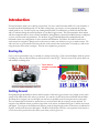
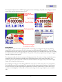
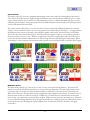
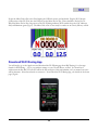
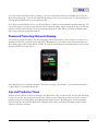
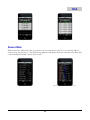
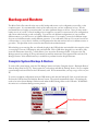
RLC ENTERPRISES, RACING DIVISION
Dash Logger User Manual – Micro Pod and Pro
This manual should be used for quick reference and on track use
for the Micro Pod and Pro units.
Copyright Notice. All materials copyright © 2012, R.L.C. Enterprises, Inc., all rights reserved.
Micro Pod and the Micro Pod Logo are Trademarks of R.L.C. Enterprises, Inc.
R.L.C. Enterprises Reserves the Right to Change Specifications without Notice.
Revision 2.6
February 29, 2012
Table of Contents
Uploading Race Log Files
CHAPTER 1- INTRODUCTION
Booting Up
Getting Around
Copying Log Files From A USB Stick To A
Race Logger
Deleting Log Files
Main Menu Screen
Copying Backup Log Files
Racing Screens
CHAPTER 7 – SYNCHRONIZED VIDEO
Sensor Screens
ChaseCam PDR Camera
Warning Screens
Connecting to the ChaseCam PDR
GLC Indicator Field
Verify Connection
Lap Times, Predictive and Split
Verify ChaseCam PDR Recording
Times
GoPro Camera
Stopwatch/Lap Counter
Verify The GoPro Camera
Shift Lights
Setup The GoPro Camera
Connecting to the GoPro Camera
CHAPTER 2 – USER PREFERENCES
LED Brightness
Touch Panel Calibration
CHAPTER 3 – CALIBRATING SENSORS
Throttle Calibration
Steering Calibration
Verify Connection
Sony/Canon Camera
Verify The Sony/Canon Camera
Connecting to the Sony/Canon Video Camera
Verify Connection
Removing Power
Brake Calibration
ChaseCam Camera
Gear Position Calibration
GoPro Camera
CHAPTER 4 – GPS
Sony/Canon Camera
Setting the Start/Finish Line
Downloading Synchronized Video Log File
Load a Saved Start/Finish Line
GoPro Camera
Save a Start/Finish Line
Sony/Canon Camera
Creating a GPS Track Map
Exact Track Map
Corrupt Synchronized Video File?
CHAPTER 8 – ADDING WIFI
GPS Lap Timer
Downloading Wi-Fi Racing App
GPS Predictive Lap Timer
Password Protecting/Network Naming
GPS Split Lap Timer
Lap and Predictive Times
GPS Connection Time
Sensor Data
CHAPTER 5 – RACE REPLAY
CHAPTER 9 – BACKUP & RESTORE
Replaying a Race
Complete System Backup & Restore
Replay Information Screen
Car Configuration
CHAPTER 6 – OFFLOADING RACE LOG
FILES
Ch.1
Introduction
First and foremost, thank you for buying our products. You are a valued customer and R.L.C. looks forward to a
mutually beneficial relationship with you. In order to help insure your success, we have prepared this getting
started guide for you. Use this step-by-step Getting Started Guide/User Manual to get started for the first time
and as a reference during the normal operation of your Race Logger system. This user manual has been written
with the assumption that you have correctly installed the wiring harness, connected and added sensors, configured
your car, and set certain user preferences. See the Race Logger Technical Manual for technical details and
information about car configuration or sensor creation and calibration. The Micro Pod and Pro units have a
touch screen for navigation. Simply touch on the screen to make your selection or to get to another screen. We
will cover how to get around the unit using only the touch screen in the section below. Generally you will not be
using the mouse at the track to navigate. A mouse is not required to get around.
Booting Up
Once you have powered the unit, you should see a startup screen (Fig 1). This screen will display while the system
is loading for a few seconds and then you will see the race screen (Fig 2). The race screen is the screen which you
will normally use during races.
Touch here to
navigate to another
screen.
Figure 1 - Startup Screen
Figure 2 – Race Screen
Getting Around
Navigating through the different screens and sub-screens of the race logger systems is easy; simply use the touch
screen on the Micro Pod or Pro unit to get around. You can also use the mouse that is included with the Micro
Pod Setup kit to navigate your way through your unit but you probably won’t be using the mouse at the track.
The user manual has been written to assume that you are at the track and do not have a mouse attached. To
navigate to the different screens, touch the top portion of the screen, as indicated in Figure 2, and the next screen
will appear. To navigate to the different sub-screens, touch the bottom right portion of the screen, as indicated in
Figure 4, and the next sub-screen will appear. The Micro Pod and Pro unit has a very responsive touch screen so
you do not need to press hard on the screen, even when you have gloves on.
1
Ch.1
There are four main screens on the RLC race loggers; the race screen (Fig 2), the qualify screen (Fig 3), the sensor
screen (Fig 4), and the main menu screen (Fig 5).
Stopwatch
Touch here to
navigate to another
screen.
Lap Counter
Gear Position
Figure 2 – Race Screen
Figure 3 – Qualify Screen
Tachometer Bar
Figure 4 – Sensor Screen
Figure 5 – Main Menu Screen
Touch here to navigate
to another sub-screen.
Racing Screens
There are three screens that a driver will use while the car is moving: the racing screen (Fig 2), the qualifying
screen (Fig 3), and the sensor screen (Fig 4). Each screen is used for slightly different purposes. To navigate to
the different screens touch on the top gauge bar, as indicated in Figure 2, on the Micro Pod or Pro unit. Touching
the tachometer bar will scroll through the screens. To get back to any screen, simply keep touching on the gauge
bar until the desired screen appears.
The racing screen (Fig 2) is the main screen used during an actual race. It consists of a large colorful tachometer,
numerical value of the tachometer, selectable gauges for displaying engine vitals, current speed (mph), gear
position, lap counter, and a stopwatch. If there is an alternate screen for the engine vitals, touch on the far right
engine vital to display the alternate sensor.
The qualifying screen (Fig 3) is used during qualification or any time you want to keep an eye on your lap times.
The qualification screen has everything the race screen has but adds current and best lap times to the bottom of
the screen. Knowing your best lap throughout qualification is extremely useful because you don’t have to wear
your tires out during qualify. You just stay out on the track as long as it takes to get a lap time you are satisfied
with.
2
Ch.1
Sensor Screens
The sensor screen (Fig 4) shows a graphical representation of the sensor with a real-time update of the sensor’s
value. Touch the sensor screen to toggle through the different sensor screens that are available (Fig 6-11). Some
sensor screens will have easy to follow, on-screen instructions on how to calibrate that particular sensor, see the
calibrating sensors chapter. This screen is also where the GPS information can be found, see GPS chapter below
for more information about the GPS.
The sensor screens visibly allow you to view the value of sensors and provide calibration options for common
sensors. For less common sensors you can use the generic sensor screens (Fig 10 and Fig 11). To toggle between
the different sensor screens, if the sensor was assigned a graphic, touch on the sensor screen box on the Micro
Pod or Pro unit (active area shown in Fig 4). The sensor screens toggle in a circle so you can always get back to
the sensor screen you want to view. When you toggle back to the race or qualify screen and back to the sensor
screen, the unit will remember which sensor you were viewing and come up displaying that sensors data. Below
are examples of some common sensor screens and the generic sensor screens provided on the RLC Race Loggers.
Figure 6 – EGT Sensor Screen
Figure 9 – Breaking Sensor Screen
Figure 7 – Steering and Throttle Sensor Screen
Figure 10 – Generic Sensor Screen
Main Menu Screen
Figure 8 – GPS Set Up Screen
Figure 11 – Generic Sensor Screen
The main menu screen (Fig 5) is the screen you use to set up your car and user preferences. This screen will
mainly be used in the technical manual when you set up your car configuration. The race replay function is the
only screen that you can access in the main menu without a USB device, such as the mouse, connected to the
Micro Pod or Pro unit. The race replay screen is explained in a later chapter in this manual. To access the rest of
the main menu screens you will have to plug in a USB device. We block the rest of the functions on the main
menu so that you cannot alter your car set up by accident. While out at the track, the only function you will need
to access is the file manager which has all your logged session files in it. Simply plug in your USB memory stick to
access the files, see the offloading race log files chapter below for directions on how to transfer your logged
session files.
3
Ch.1
Warning Screens
Warning screens appear when preset warning levels have been crossed. These levels are user definable and are set
during each sensor setup. Please see the technical manual on how to set the warning levels for each sensor. Two
levels of warnings are set, an initial warning level and a final warning level. The initial warning level is the value at
which you want to be alerted to a potential problem. When this value is reached it will blink the corresponding
gauge red as seen in Figure 12. The final warning level is the value at which the car should be pitted so that you
can investigate the problem. When this value is reached the entire screen will turn red (Fig 13) and requires the
driver to acknowledge the warning by touching the touch screen in order to override it and return to the racing
screen.
Figure 12 – Initial Warning
Figure 13 – Final Warning
GLC Indicator Field
The GLC indicator field is a useful tool for drivers to know whether you are connected to satellites, logging, or if a
camera is attached. The ‘G’ stands for GPS, it will blink on and off when it is connecting to satellites. It will be
orange when it first connects and change to green when it has connected to a differential satellite. The ‘L’ stands
for logging and it will turn green when the Micro Pod or Pro unit has started logging data and will turn off when it
stops logging. The ‘C’ stands for camera and it will blink on and off while the ChaseCam camera system is
powering on and stay green when the camera is ready to start recording.
Lap, Predictive, and Split Times
Lap times are displayed during the race and require no user intervention. Lap, predictive, and split lap times need
to be set up in the GPS screen. Please see the GPS chapter on how to set up the lap timers. Lap times, predictive
and split times are flashed on screen and remain on screen for a set amount of time (Fig 14, 15, and 16). The
amount of time a lap time stays on the screen is set by the user. The default time is 5 seconds, if you want to set a
different amount of time the lap time is displayed, please see the technical manual. Below the lap time is a value
that tells you if you were faster or slower than your fastest lap time. The predictive lap time displays the time
difference between your best lap time and your current lap time at that particular spot on the track. The split lap
time displays your time between the markers you set on the track and the time difference between your best time
and your current time. Lap times, predictive, and split lap times will only pop up in the race screen and the qualify
screen. They will not pop up if you are in the sensor screens.
4
Ch.1
Figure 14 – Lap Timer
Figure 15 – Predictive Lap Timer
Figure 16 – Split Lap Timer
Stopwatch / Lap Counter
The stopwatch and lap counter are displayed on the race and qualify screen (Fig 17). The lap counter keeps track
of number of completed laps you have made; it will increase every time you cross the start/finish line and
complete a lap. Please see the setting the start/finish line section below on how to set the start/finish line. This
feature allows you to see the lap number and time any section of a track independent of the system lap timer. You
can use the stopwatch to know how long you have been on the track and how long until the end of a timed race.
The stopwatch automatically starts when you reach logging speed.
Stopwatch
Even though the start watch automatically starts Lap Counter
when you start logging you can start the stop watch
manually as well. To start the stopwatch on a Micro
Pod or Pro unit, touch the stopwatch area. To stop
the stopwatch, touch the stopwatch area. To reset
the stopwatch, touch and hold the stopwatch area
for 3 seconds.
Figure 17 – Lap Counter and Stopwatch
Shift Lights
The shift lights are dual colored red/green lights and
are used as rpm/gear shift indicators. The shift
points & rpm levels are user programmable in the
car setup menu which is covered in the technical
manual. The LED display style (left-to-right, out-toin) is user-defined in the display setup menu.
Bright, Dual Colored
LED Shift Lights
Figure 18 – Micro Pod With Shift Lights
5
Ch.2
‘Touchscreen’ button (Fig 19). Figure 20 will appear;
follow the onscreen instructions and the touch
screen will be calibrated and saved. When finished,
press the ‘Save Car’ button (Fig 19). This procedure
can be repeated until the touch screen response is
acceptable, but this procedure should not have to be
performed very often if at all.
User Preferences
LED Brightness
The shift light LEDs have different brightness levels,
low, mid, and high, that the user can set. The Micro
Pod and Pro units are shipped with factory set low,
mid, and high brightness levels. If these levels are
not sufficient for you please contact RLC.
Adjustable Brightness!
When setting user preferences you must have a
mouse plugged into the USB port so that you are
able to fully access the main menu screen (Fig 5). To
set the brightness of the unit, navigate to the screen
setup screen. Touch on the top part of the LCD
until the main menu screen appears and press the
‘Screen Setup’ button (Fig 19). To select the
brightness level touch or click on the brightness level
box to reduce or increase the brightness level. The
brightness will scroll through low, mid, and high
settings. Both the LEDs and the LCD dim on the
Micro Pod and Pro units. Clicking the LED Scheme
box will change the pattern of the LED’s, according
to RPM. Current options include left-to-right & outto-in. Clicking the box will give you a preview of the
currently selected pattern.
Figure 19 - Screen Setup Screen
There is a quick way to change the LED brightness
on the Racing Screen. Simply press and hold on the
MPH area and you will see the LED brightness
change.
Touch Panel Calibration
Micro Pod and Pro units are calibrated in the factory,
but users have the option to recalibrate if necessary.
To calibrate your touch screen, simply touch the
Figure 20 – Touch Screen Calibration Screen
6
Ch.3
Calibrating Sensors
The sensors in this section have to do with the set up of the car and are the sensors that are most affected when
you make a change to your cars setup. Since these sensors need to be calibrated more regularly, we have made it
easy to do so. In order to calibrate these sensors you will have to be in the car and the unit must have been
correctly installed in the car along with the sensors. Whenever the car’s setup is changed, i.e. the tires are changed,
you must recalibrate the sensors that were affected by the change. The sensors must be recalibrated so that the
R.L.C. race logger will take correct data. To calibrate all these sensors you will need to navigate to the appropriate
sensor screen. To get to the sensor screens touch the top tachometer bar until you get to the sensor screen (Fig
4). Once the sensor screen has appeared click on the sensor box until the sensor you want to calibrate appears.
Please refer to Chapter 1 Getting Around.
Throttle Calibration
To calibrate the throttle sensor navigate to the steering and throttle sensor screen (Fig 21). Press and hold the
‘Calibrate Throttle’ button and follow the on-screen instructions to start throttle calibration. This screen will only
appear if you have a throttle position sensor installed.
Figure 21 - Throttle and Steering Calibration Screen
Steering Calibration
To calibrate the steering sensor navigate to the steering and throttle sensor screen (Fig 21). Press and hold the
‘Calibrate Steering’ button and follow the on-screen instructions to start steering calibration. This screen will only
appear if you have a steering position sensor installed.
7
Ch.3
Brake Calibration
To calibrate the brakes navigate to the brake sensor
screen (Fig 22). Press and hold the ‘Calibrate’ button
to start brake calibration. This screen will only
appear if you have one or two brake pressure sensors
installed.
Follow the on-screen instructions to complete brake
calibration.
Figure 22 - Brake Calibration Sub-screen
Gear Position Calibration
The R.L.C. race loggers have a calibration routine that can figure out the different number of gears in the car.
This is the only calibration routine that requires the car to be moving while calibrating. To calibrate the gear ratio,
your car must have a tachometer sensor installed. Start the calibration routine while the car is in the pit lane, press
and hold the ‘Set Gear’ button (Fig 23). A window will appear that will have you choose between manual and
automatic (Fig 24). We recommend that you choose the manual mode. Automatic mode should only be used if
you have a sequential gear shift or if your gears are not close together. However, if you can reach the touchscreen
you should use the manual mode because it will find your gears every time.
Figure 23 – Set Gears
Figure 24 – Select Gear Ration Mode
Figure 25 - Gear Position Calibration
When you click on the ‘Manual’ button another window with instructions will appear (Fig 25). This screen will tell
you which gear you are going to record next. Only press the ‘Set’ button when you are actually in that gear being
displayed. With the car in first gear, start driving around the track and press the ‘Set’ button on the screen to start
recording the data for first gear. You need to stay in first gear for at least ten seconds, a count down will appear
on the screen and then another window with the number 2 will appear on the screen. When you can, shift to
second gear and perform the same procedure. You need to do this for every gear. When you have finished
recording all your gears press the ‘Save’ button and you are done. Each gear that you record you need to stay in
that gear for at least ten seconds, you can stay in the gear as long as you want or shift to other gears in the
meantime. For example, if you are trying to record 5th gear and you won’t be able to get into 5th gear until a half
way around the track, don’t worry. Drive like normal, downshifts and up shifts, and when you get to the length of
8
Ch.3
track where you can hit 5th gear, then press the ‘Set’ button. You can always leave the window in Fig. 25 displayed
while you drive around the track and press the ‘Set’ button when you can get into the displayed gear.
When you click the ‘Automatic’ button (Fig 24) follow the on-screen instructions, you will need to drive the car
around the track for approximately 2 minutes. Make sure to use all gears, through their full range for equal
amounts of time. Avoid using the clutch and do not break tires loose during this calibration. When finished, the
Micro Pod or Pro unit will display the number of gears it found and give you the option to save or cancel the
calibration it found. If the information calculated was correct save the gear ratio information otherwise, cancel the
ratio calibration and retry.
If you change your gear ratios you will have to go through this calibration again so that the unit can find the gears
again. Simply follow the steps above, but instead of pressing and holding on the ‘Set Gear’ button, press and hold
on the gear being displayed. Note: The Micro Pod and Pro unit allows the user to save different car
configurations under different names. This means you can have different gear ratios saved under different names
so all you have to do is load in a new car configuration so you don’t have to go through the gear position
calibration every time you change your gears. Please see the technical manual for more details about car
configuration files.
Hold Here For
3 Seconds
Figure 23 - Gear Position Calibration
9
Ch.4
GPS
GPS is included with all Micro Pod and Pro units, which allow you to get exact track maps, lap times, predictive
times, and split times. Standard GPS units included with your Micro Pod or Pro units are the 20 Hz. We
recommend that you place the GPS antenna somewhere on the center line of your car (away from the engine
compartment or any type of electrical noise), in clear view of the sky, and horizontal or parallel to the sky.
When connecting the GPS for the first time it could take upwards of an hour to lock onto satellites and start
transmitting data, due to a significant change of position. When making a connection for the first time make sure
the antenna is in clear view of the sky and the cord is completely uncoiled. After the GPS has established a
connection for the first time, connecting to satellites can take as little as 5 seconds to a maximum of 1 minute.
While the GPS is trying to connect the ‘G’ in the indicator field will blink green but when the GPS has connected
the ‘G’ on the screen will stay orange and turn green when a differential signal has been attained.
If you would like to verify that the GPS is working and connected properly, you can either look for the
orange/green ‘G’ in the indicator field or navigate to the GPS screen (Fig 26). On the Micro Pod or Pro unit
touch the tachometer bar until the sensor/calibration screen appears (Fig 4), then touch inside the sensor box until
you get to the GPS screen (Fig 26). Refer to Chapter 1, Getting Around, for more exact instructions for
navigating through the screens. The GPS data is displayed in this screen; the number of satellites the GPS is
locked on to, signal quality, and the latitude and longitude of your location. The GPS unit will take a couple of
minutes to connect to the satellites. Make sure you are outside when trying to verify GPS, it won’t always work
inside. If there is an error connecting it will indicate that there is no GPS connected.
Figure 26- GPS Timing Setup Screen
Figure 27 - GPS Screen to Setup Start/Finish Line
Setting the Start/Finish Line
A start/finish line must be set on your unit so the pop up lap timer, lap counter, and predictive lap timer works
properly. You must be moving forward and on the track (not in the hot pits) when you set the start/finish.
Usually you set the start/finish line on your first lap around the track. Once the start/finish line has been set, your
unit will remember it until you drive a different track and/or set a different start/finish line. This start/finish lap
will also be recorded as your base lap for when the unit is in predictive mode. To read more about predictive lap
timing, see the GPS predictive lap timer section below.
10
Ch.4
To set the start/finish line, navigate to the GPS setup screen (Fig 26). By default, the unit is in predictive mode.
Hold the ‘Enter Setup’ button. Another screen will appear (Fig. 27) that allows you to set the start/finish line.
When your car passes the spot on the track that you want to mark as the start/finish line press the ‘Set’ button.
Make sure you drive a complete lap around the track so that your base lap for predictive lap timing will be
established. Once the start/finish line has been set, the unit will automatically switch to the qualify screen (Fig 3).
Load A Saved Start/Finish Line
If you have a start/finish line saved you can load it so you don’t have to set a one. To load a saved start/finish,
navigate to the GPS setup screen (Fig 26). By default, the unit is in predictive mode. Hold the ‘Enter Setup’
button. Another screen will appear (Fig. 27) that allows you to set or load a start/finish line. Press the ‘Load’
button. The Load Start/Finish screen will appear (Fig 28). Select the desired start/finish line from the list and
press the ‘Load’ button. The selected start/finish line will now be set. You will need to drive at least one
complete lap so the predictive lap timing can be set up. After the first complete lap has been driven, you will
receive lap and predictive times on the screen.
Figure 28 – Load A Start/Finish Line
Save A Start/Finish Line
RLC allows users to save start/finish lines so they can use them in the future. Use the steps in the Setting the
Start/Finish Line section above to set a start/finish line. To save the start/finish line that you just set please see
the Technical Manual.
Creating a GPS Track Map
GPS is the most accurate & precise way to map a track. Every lap that you take around the track is distinctive and
unique. Unlike mapping a track with G-Force, just a single lap will render an accurate map based on your exact
line you drove. G-Force requires that you make multiple laps and then the PC software will average your laps and
create a track map based on those averages. Each lap will look exactly the same and the data can be off as much
as 30 ft! With RLC, each lap will look different because each line you drive around the track is slightly different.
The data that is recorded from each lap is accurate to within inches. R.L.C. does not average and compress your
data to create a track map; instead our software creates a track map based on each individual lap. The Race
Analyzer software creates a track map based on how much of the track you drove on (Fig 29). The left side of the
11
Ch.4
track will be the leftmost line your car drove on the track and the right side will be the rightmost line your car
drove. The narrower the track means that you drove close to the same line every time you drove that part of the
track. Now when you analyze your data on the Race Analyzer software, each lap will appear within the track that
was created by your car. The track map that was created is specific to the data for that particular session. Each
session will render a different track map because your drive differently every time.
Figure 29 – Track Map
Exact Track Mapping
R.L.C. offers Exact Track mapping which is the most precise way to map a track. Exact Track allows you to see
your lines within the width of the actual track. We do this by driving the right and left sides of the track so that
you are able to get the exact widths everywhere along the track (Fig 30). When you load your log files in our Race
Analyzer software, your laps are shown within the width of the track. You can see the exact lines you drove
everywhere on the track and you are able to find the fastest line. You only have to create a track once and you
have the track forever. You can even check at R.L.C.’s website to see if the Exact Track map has already been
made and download it.
12
Ch.4
Figure 30 – Exact Track Map
Figure 31 – Exact Track Map, Close Up
To create an Exact Track map make sure that you have a differential GPS lock. You can check to see if you
have a differential lock by navigating to the GPS track mapping screen (Fig 32) and if you see differential you are
locked in, if not give it some more time. A differential lock will ensure that you get the most accurate track map.
Before you go out onto the track, like while in the hot pits, press and hold the ‘Start’ button. A different GPS track
mapping screen will appear prompting you to press ‘Start’ or ‘Cancel’ (Fig 33). Once you are in the track mapping
screen, drive out onto the track and place you tires as close to the edge of the track as you can (you choose which
side you want to drive first). When you are ready, press the ‘Start’ button; a screen will appear that displays the
distance traveled and the distance to the start (Fig 34). Drive the left side of the track. Drive past your initial
staring point and then cross over to the right side of the track. Again place your tires as close to the edge of the
track as possible and drive the right side of the track. Drive past your initial starting point and press the ‘Stop &
Save’ button and the Exact Track Map is saved. The car must travel in the same direction for each lap. If for any
reason you want to abort the track mapping press the ‘Cancel’ button.
You want to drive around the track as slow as you can. If you have the 5 Hz GPS you want to stay around 20-25
mph (32-40 kph) and with the 10 Hz GPS around 25-30 mph (40-48 kph). The slower that you drive the closer
together the GPS samples are, this creates a more accurate and smooth track map. The track map will be one of
the log files. Send the log file (.bin) to RLC Racing and they will create the Exact Track map so that you can use it
in the PC software. Make sure you include what track it is, the configuration (if there are alternates), website to the
track, and any additional information that may be helpful. RLC Racing will use this information and Google
Earth to add rumble strips, buildings, flag stations, bleachers, and any other track characteristics we can see. We
will send you the Exact Track map file (.map) and now you can analyze your data within the confines of the actual
widths of the track. You will have to drive one complete lap before the lap timer and predictive lap timer will
work.
13
Ch.4
Figure 32 - GPS Track Mapping Screen
Figure 33 - GPS Track Mapping Screen
Figure 34 - GPS Track Mapping Screen
GPS Lap Timer
GPS is used to measure lap times instead of a stationary beacon you have to place on the track. GPS is more
exact and it eliminates the need of buying an expensive lap timer. The GPS lap timer is automatically set up once
you set the start/finish line, which was covered in an above section. Now your lap time will pop up on your unit
every time your car crosses the start/finish line (Fig 35). Also displayed is the difference between you current lap
time and your fastest lap time. If your lap time is faster then it will be (-) in red and if the lap time is slower then it
will be (+) in green.
Figure 35– Lap Timer
GPS Predictive Lap Timer
Predictive lap timing is a great tool when you want to try new things on the track and need some instant feedback.
When the race logger is in predictive mode, it will inform you of the time difference at that current location on the
track between your current lap and your fastest lap (ever), so you know if things are helping or hurting (Fig 36). If
you are currently faster than your fastest lap then the time difference will be (-) in red and if you are currently
slower then it will be in (+) green.
14
Ch.4
Figure 36 – Predictive Lap Time
Figure 37 – Predictive Setup Screen
To set the predictive lap timer, navigate to the GPS set up screen (Fig 26). Touch the ‘Predictive’ button and
then press and hold the ‘Enter Setup’ button. Another screen will appear (Fig 37) that will prompt you to set or
load your start/finish line. If you already went through the steps to set or load a start/finish line and made a
complete lap, then you do not need to record a base lap. A base lap is needed so that the unit can set up the
markers needed for predictive lap timing. You can exit out of this screen by touching on the tachometer bar on
the top of the screen. If you would like to record a new base lap simply press and hold the ‘Enter Setup’ button
then press the ‘Reset Times’ button and drive a complete lap around the track. You can also establish a new base
lap by setting a new start/finish line and driving a complete lap. The reason that you may wish to record a new
base lap is if the weather conditions change and you want to reset your fastest lap. Your fastest lap is what your
predictive lap times are based off of so it makes sense to have a fastest lap for the current weather conditions.
Comparing laps from a sunny day to a rainy day doesn’t make sense.
GPS Split Lap Timer
The split lap timing feature on the RLC race loggers lets you divide up the track to work on specific sections to get
your lap times down. By setting markers, you can section off the parts of the track you want to work on. You can
set up to four markers on the track to make either two different sections or three consecutive sections. When the
unit is in split mode it will display the time it took to get through the markers you set and the difference between
your current time and your best time (Fig 38). If you were faster than your fastest time then the time difference
will be (-) in red and if you are currently slower then it will be in (+) green.
Figure 38 – Split Lap Time
Figure 39 – Split Setup Screen
15
Ch.4
To set the split lap timer, navigate to the GPS set up screen (Fig 26). Touch the ‘Split’ button then press and hold
the ‘Enter Setup’ button. Another screen will appear (Fig 39) that will allow you to set a split beacon. Press the
‘Set’ button once before and once after the section of track that you want to work on. You can choose to set all
four markers or just two. Now every time you cross the marker the time will start and it will stop when you cross
the next marker. Your time will flash up on the screen along with the time difference between your current run
and your fastest run. You can exit out of this screen by touching on the tachometer bar on the top of the screen.
GPS Connection Time
When connecting the GPS for the first time it could take upwards of an hour to lock onto satellites and start
transmitting data, due to a significant change of position. When making a connection for the first time make sure
the antenna is in clear view of the sky and the cord is completely uncoiled. After the GPS has established a
connection for the first time, connecting to satellites can take as little as 5 second to a maximum of 1 minute.
While the GPS is trying to connect the ‘G’ in the indicator field will blink green but when the GPS has connected
the ‘G’ on the screen will stay green.
To view how many satellites your GPS unit is connected to, navigate to the GPS setup screen on the Micro Pod
or Pro unit (Fig 26). This screen will show you how many satellites you are connected to and if you are connected
to the differential satellite. When the GPS initially connects, it will only be connected to maybe 4 satellites. As the
GPS units stays on it will connect to more satellites automatically.
16
Ch.5
Race Replay
Reviewing any logged session on your unit is easy to do with R.L.C.’s exclusive race replay function. It is useful
for quick, trackside replays when no laptop is available. The replay screen has a familiar VCR type control panel
that lets you playback, stop, step backwards, step forwards, and pause the replay session. While the unit is in
replay you can scroll through the different race screens and sensor screens so that you can view the data as it
happened on the track.
To replay a logged session navigate to the race replay screen by simply touching on the top tachometer bar unit
the race replay screen appears (Fig 40). You can always connect the mouse that was provided in your kit to make
selecting certain buttons easier but everything can be done without a mouse.
Filename Box
Summary Box
Replay Control Panel
Figure 40 - Race Replay Screen
The race replay screen (Fig 40) has a filename box, a summary box, and race replay controls. The filename box
contains all of the logged files that are available for replay. The summary box gives you the date, time elapsed, car
name, laps completed, and best lap time for the highlighted session. The race replay control panel controls how
fast or slow the replay plays; how the replay control panel works is described in the section below.
Replaying a Race
Select which file you would like to replay by
touching on the file. Once you have selected the
desired file touch the ‘On’ button. To start playback
on the Micro Pod or Pro unit you need to touch on
the top sensor bar which will bring up the playback
screen (Fig 41) and then press the play button.
Replay Control Panel
Figure 41 – Replaying a Race
17
Ch.5
While a race is being replayed it can be controlled through the control panel on the top left of the screen(Fig 41)
to fast forward, pause, or rewind the race. Simply touch on the action you want. While the unit is in replay you
can scroll through the different race screens and sensor screens by touching on the tachometer bar or in the
sensor box. Please refer to the getting around section on how to navigate through these screens.
The race replay control panel also has a ‘W’ or warning button and an ‘L’ or lap timer button. When the ‘W’ or
warning button is activated the warning screen will appear (Fig 42) and when the ‘L’ or lap timer button is
activated the lap timer will flash on screen (Fig 43). To view these screens, touch on the appropriate button.
Figure 42 –Warning Screen
Figure 43 – Lap Timer
When you want to stop the replay, navigate back to the race replay screen (Fig 40) by touching on the tachometer
bar. Once in the race replay screen touch the ‘Off’ button.
Replay Information Screen
The replay information screen is a sensor screen that
is only available during race replay (Fig 44). It is a
brief summary of sensors, speed, and time that is
useful during replay. Read the getting around
section on how to navigate to the sensor screen.
Again if you have to have a throttle position sensor
connected for the throttle portion of the race replay
screen to work.
Figure 44 – Replay Info Screen
18
Ch.6
Race Log Files
Each time you go out on the track the race logger creates a logged file session. The amount of data in the log file
depends upon the logging rate of each installed sensor. See the technical manual on how to set sampling rates on
installed sensors. These logged sessions can either be played back on your unit (Ch 6) or downloaded to your PC
to analyze the data with the RLC Race Analyzer. To transfer the logged session files from your Micro Pod or Pro
unit to a PC you only need to connect a USB memory stick, there are no extra cables to attach just the USB stick.
Make sure the car is not running before you upload, copy, or delete files from the Micro Pod or Pro unit. Each
time you offload a log file it makes a copy and stores it in a backup folder on the Micro Pod or Pro unit for future
use.
Uploading Race Log Files
To transfer a logged session from Micro Pod or Pro unit to a PC you will need the USB memory stick that was
included in the optional Micro Pod Setup kit but also available at your local office store. Insert the USB memory
stick into the connector on the harness. The race logger will scan the USB stick for logged files and compare
them to the log files on the race logger itself. If the race logger contains files that the USB stick does not it will
display the number of files found and a pop up window will prompt the user to copy all files, copy and delete files,
or cancel (Fig 45). The copy only option will scan the USB stick and copy all logged session files not already on
the USB stick. The copy and delete option (recommended) will copy all new logged session files over to the USB
stick and erase the file from the race logger itself. Choosing the option to copy and delete is a much faster way to
offload your logged session files. The cancel option will close this pop up window. You would choose this
option if you want to manually transfer files, see below. Select an option by pressing on the appropriate button.
With the logged sessions now on your USB stick, you can load them into the RLC Race Analyzer software and
study your data. You can also leave the USB stick plugged into the harness while you are out on the track. With
the USB stick plugged in, the logged session files will automatically download to the USB stick when the session is
done. Every time you offload a log file from the Micro Pod or Pro unit it will automatically create a backup file.
This backup file is stored in a backup file directory on the Micro Pod or Pro unit for future use. Please see the
section below on how to copy and offload a backup file form the Micro Pod or Pro unit.
Figure 45– USB Stick Plugged In
19
Ch.6
If you would like to copy the files over manually you will have to connect the USB hub so that you can connect
both the mouse and the USB memory stick. Navigate to the File Manager screen by touching on the top
tachometer bar until the main menu screen appears (Fig 7) then click the ‘File Manager’ button. With a mouse or
stylus select the ‘Log Files – Transfer To/From USB Stick’ option from the dropdown menu (Fig 46). Select the
log file you want to transfer to the USB memory stick from the ‘Local Logs’ section. When the log file is
highlighted, click the
button. The file will transfer from the race logger to the USB memory stick. Now you
can take that file and import it into the RLC Race Analyzer. If you want to copy over an entire folder and its
contents you can use
.
Dropdown Menu
Copy Single File
Figure 46 - File Manager Screen
Copying Log Files From a USB Stick to a Race Logger
Log files can also be copied from a USB stick to a Micro Pod or Pro unit. Using the same steps above select a file
that is already on a USB stick and click the
or
buttons.
Deleting Log Files
To delete a file from either a USB stick or from the
data logger, select the file to be deleted and press the
button. There is no undo for this operation so a
popup box will prompt the user for a final
confirmation (Fig 47).
Figure 47 – Deleting A File
20
Ch.6
Copying Backup Log Files
Every time you offload a log file from the Micro Pod or Pro unit it will automatically create a backup file. This
backup file is stored in a backup file directory on the Micro Pod or Pro unit for future use. To offload one or all
of these backup files click on the ‘Logging’ button. On the bottom right of the logging screen (Fig 48) you will see
a section showing you the number of backup files currently on your Micro Pod or Pro unit and how much space
they are taking up. Simply plug in the USB stick that was provided in the optional Micro Pod Setup kit and click
the ‘Copy to USB’ button. Your backup log files will start to copy onto your USB stick. With the logged sessions
now on your USB stick, you can load them into the RLC Race Analyzer software and study your data. You can
also choose to delete the backup files from your Micro Pod or Pro unit by clicking the ‘Delete All’ button.
Figure 48– Backup Log Files
21
Ch.7
Synchronized Video
R.L.C. Racing makes synchronized video easy! The Micro Pod units connect directly to GoPro, ChaseCam, and
certain Sony and Canon video cameras and remotely control them. The RLC data logger will control the camera
by turning it on and start recording when race dash starts to log data. When the RLC race logger stops logging
data it will send a signal to the camera to stop recording and turn off. You will never again have to worry about
turning the camera on, draining the battery, or pressing the record button; RLC does it all for you!
The Micro Pod units connect easily to the GoPro, ChaseCam, and Sony/Canon cameras with a simple video
adapter cable. The RLC race logger will help to conserve battery life by turning the camera on and off and
conserve memory space by starting and stopping recording only when you are out on the track. Now you can
concentrate on your driving because everything else is already being taken care of by your RLC data logger.
Synchronizing the video file to the data file is extremely easy with the Pro Race Analysis software. Since the RLC
race logger controls the GoPro or Sony/Canon camera, the two files are already semi-synchronized. Once you
synchronize the two files they are saved into one file and you never have to do it again. Now when you click
anywhere on the track map the video and data will jump to that exact position. Customers using a ChaseCam
camera do not have any manual synchronization to do because the data is already embedded into the video file.
If you have not installed your GoPro, ChaseCam PDR, or Sony/Canon camera please read the Technical
Manual on how to install, setup and connect it to the Micro Pod or Pro unit correctly.
ChaseCam PDR Camera
then plug into the back of the ChaseCam PDR (Fig
49). If you have the old style harness then plug the
cable that is labeled Video directly into the back of
the ChaseCam PDR. When plugging in cables,
make sure the car is turned off and there is no power
to the ChaseCam PDR or Micro Pod or Pro unit.
The ChaseCam PDR needs to have its own source
of power; again we recommend that you wire
directly to the battery, and needs to share the same
ground as the Micro Pod or Pro unit.
Connecting To The ChaseCam
PDR
Make sure that Micro Pod or Pro unit is off before
you connect to the ChaseCam camera. If you have
the new style harness a standard Ethernet cable is
used to connect the Micro Pod or Pro unit to the
ChaseCam PDR (do not use a cross over cable). If
you purchased your ChaseCam PDR from RLC
then the video cable was included, otherwise you can
either order a video cable from RLC or from a local
office supply store. Plug the video cable into the
connector on the harness that is labeled ‘Video’ and
Figure 49 – Micro Pod or Pro unit Connected to ChaseCam PDR
With the Micro Pod or Pro unit plugged into the
ChaseCam PDR the RLC unit will completely
22
Ch.7
control the camera; it starts recording when the
Micro Pod or Pro unit starts logging and stops
recording when it stops logging. There are no
special settings that you need to do on the Micro
Pod or Pro unit, it will automatically connect and
control the ChaseCam camera.
Verify ChaseCam PDR Recording
When you have successfully verified that your
ChaseCam PDR is connected to your Micro Pod or
Pro unit you need to verify that it is recording
properly. The Micro Pod or Pro unit will completely
control the ChaseCam PDR; it will tell the camera to
start recording when the RLC unit starts logging and
tell it to stop recording when the RLC unit stops
logging. On the race screen of the Micro Pod or Pro
unit you will see the GLC indicator. When the L
illuminates green this means that the RLC unit is
logging data (Fig 50). Check the light on the front of
the ChaseCam PDR, it should be flashing red to
indicate that it is recording (Fig 52).
Verify Connection
When you successfully set the ChaseCam PDR up
and have connected it to the Micro Pod or Pro unit
it is time to verify the connection. Start your engine
and look at the screen of the Micro Pod or Pro unit.
You will notice on the race screen of the Micro Pod
or Pro unit there is a GLC indicator right above the
MPH (Fig 50). When the unit recognizes that you
are connected to a ChaseCam camera the C will
blink on and off green until the camera is ready to
start recording. When the camera is ready to start
recording the C will stay illuminated green.
Figure 52 – ChaseCam PDR Light Red
GoPro Camera
The Micro Pod or Pro can interface with a GoPro
camera. It will turn it on and start recording when
the Micro Pod or Pro starts logging data and stop
recording when it stops logging data. If you are
using a GoPro camera with the Micro Pod or Pro
you will need to manually synchronize the video file
to the log file using the Pro Race Analysis software.
For more details about manual synchronization
please see the Pro Race Analysis software manual on
the website.
Figure 50 – GLC Indicator
Also look at the ChaseCam PDR. When it is ready
to start recording the light on the front will be solid
green (Fig 51).
Verify The GoPro Camera
There are 3 different models for the GoPro Hero
camera. The HD HERO 1080 with the HERO Bus
Port (Fig 53) is the correct model that will work with
the Micro Pod or Pro.
Figure 51 – ChaseCam PDR Light Green
23
Ch.7
need to get a video extension cable to lengthen the
connection (RLC sells a video extension cable).
Verify Connection
Apply power to the Micro Pod or Pro. You will
notice that the GoPro camera will turn on and it will
automatically turn off once the Micro Pod or Pro
has fully booted up. When the Micro Pod or Pro has
started logging data (the L in the GLC indicator field
will illuminate green) the GoPro camera will turn on
and start recording. When the Micro Pod or Pro has
stopped logging data (L will turn off) the GoPro will
stop recording and turn off.
Figure 53 – HD HERO 1080 Camera
Sony/Cannon Camera
The HERO Bus Port is where the CAB-VID-GP
(GoPro Camera Cable) that you purchased from
RLC will plug in. Note: You will need to router out
the back of the case to accommodate the cable.
The Micro Pod or Pro can interface with a Sony or
Canon video camera with a remote jack integrated
into the AV remote terminal. It will turn it on and
start recording when the Micro Pod or Pro starts
logging data and stop recording when it stops
logging data. If you are using a Sony or Canon video
camera with the Micro Pod or Pro you will need to
manually synchronize the video file to the log file
using the Pro Race Analysis software. For more
details about manual synchronization please see the
Pro Race Analysis software manual on the website.
Note: To connect to the Sony/Canon camera you
have to purchase a 10 pin LANC adapter cable, RLC
does not sell this cable.
Setup The GoPro Camera
The GoPro camera needs to be set to One Button
On mode. Please refer to the instruction manual
included with your GoPro camera on how to place it
in the One Button On mode. The instructions can
also be found at the GoPro website, visit
www.gopro.com/support.
Connecting To The GoPro
Camera
Verify The Sony/Canon Video Camera
You need to make sure that the Sony or Canon
video camera you are using has the remote jack
integrated into the AV remote terminal. To verify if
you camera has this feature please visit Sony or
Canon’s official website and look up your particular
camera’s specifications. It will be listed under the
Interface specifications.
Plug the CAB-VID-GP cable you purchased from
RLC into the back of the GoPro camera. Plug the
video cable on the Micro Pod or Pro harness into
the other end. Depending on which style harness
you have, you may need to purchase an Ethernet
cable to connect to the GoPro camera (a cross over
cable will not work). If you have the female video
plug on your harness (looks like a phone plug
receptacle) you will need to purchase an Ethernet
cable to connect the Micro Pod or Pro to the GoPro
camera. If you have the male video plug (looks like
an Ethernet plug) then it can simply be plugged
directly into the CAB-VID-GP. However, you may
24
Ch.7
Connecting To The Sony or
Canon Video Camera
ChaseCam Camera
Once the Micro Pod or Pro has stopped logging it
will tell the ChaseCam PDR to stop recording, again
the light on the front will turn to solid green. If you
do not let your Micro Pod or Pro stop logging
before power is removed, you will corrupt your
synchronized video file and you will not be able to
use it in the RLC Race Analysis Software.
Plug the CAB-VID-SC cable you purchased from
RLC into the AV remote terminal on the Sony or
Canon video camera. Plug the video cable on the
Micro Pod or Pro harness into the other end.
Depending on which style harness you have, you
may need to purchase an Ethernet cable to connect
to the Sony or Canon video camera (a cross over
cable will not work). If you have the female video
plug on your harness (looks like a phone plug
receptacle) you will need to purchase an Ethernet
cable to connect the Micro Pod or Pro to the Sony
or Canon video camera. If you have the male video
plug (looks like an Ethernet plug) then it can simply
be plugged directly into the CAB-VID-SC.
However, you may need to get a video extension
cable to lengthen the connection (RLC sells a video
extension cable).
GoPro Camera
Once the Micro Pod or Pro has stopped logging it
will send a pulse to the GoPro camera and it will
stop recording and turn off. If you do not let your
Micro Pod or Pro stop logging before power is
removed, it will never send the pulse to the GoPro
camera and it will continue to record until you
manually stop recording.
Sony/Cannon Camera
Once the Micro Pod or Pro has stopped logging it
will send a pulse to the Sony or Canon camera and it
will stop recording and turn off. If you do not let
your Micro Pod or Pro stop logging before power is
removed, it will never send the pulse to the Sony or
Canon camera and it will continue to record until
you manually stop recording.
Verify Connection
Apply power to the Micro Pod or Pro. When the
Micro Pod or Pro has fully booted up the C in the
GLC indicator file will illuminate green indicating
that it is connect to the Sony or Canon camera.
When the Micro Pod or Pro has started logging data
(the L in the GLC indicator field will illuminate
green) the Sony or Canon video camera will turn on
and start recording. When the Micro Pod or Pro has
stopped logging data (L will turn off) the Sony or
Canon video will stop recording and turn off.
Downloading Synchronized
Video Log File
ChaseCam Camera
When you are ready to download the synchronized
video log file so you can analyze your data in the Pro
Race Analysis software, you do so from the compact
flash card in the ChaseCam PDR recorder. It is a
.mpg file that you can play as a regular video file in a
Windows Media Player but if opened in the Pro
Race Analysis Software it will contain both the video
and the data. You do not have to download the log
file from the Micro Pod or Pro if you don’t want to
because the data is already contained in the video
file. It is the .mpg file from the compact flash card
in the ChaseCam PDR camera that you want to
Removing Power
When you have finished your session and are ready
to turn your engine off or remove power you must
wait for the Micro Pod or Pro unit to stop
logging first! The L in the GLC indicator field will
turn off when the Micro Pod or Pro has finished
logging (please see the Technical Manual on how to
set your logging preferences).
25
Ch.7
open in the PC software so you have synchronized
video file.
GoPro Camera
When you are ready to download the video file so
you can analyze your data in the Pro Race Analysis
software, you will need both the video file on the SD
card from the GoPro camera and the log file from
the Micro Pod or Pro. Once you are in the Pro Race
Analysis software you can use the tools to manually
synchronize the two files together. Please see the
Pro Race Analysis software manual for more details.
Sony/Canon Camera
When you are ready to download the video file so
you can analyze your data in the Pro Race Analysis
software, you will need both the video file on the SD
card from the Sony or Canon camera and the log file
from the Micro Pod or Pro. Once you are in the
Pro Race Analysis software you can use the tools to
manually synchronize the two files together. Please
see the Pro Race Analysis software manual for more
details.
Corrupt Synchronized Video
File?
If you find that your camera turned off accidentally
while out on the track or you removed power too
soon, your synchronized video file will be corrupt.
You cannot open it in the Race Analysis Software
but you can still view it as a standard video file.
The log file on the Micro Pod or Pro can always be
used for data analysis, even if the synchronized video
file is corrupted. The data (.bin) log file on the
Micro Pod or Pro only contains the data, not the
video. Use the USB memory stick included with the
Micro Pod or Pro to offload the log file.
26
Ch.8
Adding Wi-Fi
Wi-Fi Racing is an add on feature for the Micro Pod or Pro. With a simple Wi-Fi kit from RLC Racing you can
instantly broadcast the data being logged by the Micro Pod or Pro directly to an iTouch, iPhone, or iPad. In order
to use the Wi-Fi feature you need to get a code from RLC Racing. Please call RLC with the serial number of your
Micro Pod or Pro to get the code.
With the USB hub, USB mouse, and USB keyboard plugged in the Micro Pod or Pro unit; navigate to the
Wireless screen (Fig 62) by clicking on the top tachometer bar until the main menu screen appears (Fig 7) then
click the ‘Wireless’ button. Enter the Wi-Fi Racing code provided by RLC in the top box under Code Expires. If
you wish to password protect your data enter a passkey in the Wireless Passkey box, if not leave it set to 0. RLC
also gives you the option to name your car so it is easier to find it on the iTouch, iPhone, or iPad. Enter the name
you wish to call your car in the Wireless Car Name box. If you do not name your car it will appear as RLC-XXX
(serial number of your unit). When all the information is entered click the ‘Save Wireless Settings’ button. If you
code is correct the Changes Saved screen will appear (Fig 63) and there are instructions for you to follow.
Figure 63 – Wi-Fi Racing Code Entered
Figure 62 – Enter Wi-F Code
Click in the ‘Touch to Close’ area and your Wireless screen will now look like Figure 64, it will state that your code
is valid.
Figure 64 – Wi-Fi Racing Code Valid
27
Ch.8
Power the Micro Pod or Pro unit off and unplug the USB hub, mouse, and keyboard. Plug the Wi-Fi dongle
(USB portion of the Wi-Fi kit) into the USB port on the Micro Pod or Pro. Power the Micro Pod or Pro on.
When the Micro Pod or Pro unit powers on the Wi-Fi Racing indicator (WiFi symbol above the GLC indicator
field) will illuminate green (Fig 65). The Micro Pod or Pro is now ready to connect to an iTouch, iPhone, or iPad.
Figure 65 – Wi-Fi Racing Indicator
Download Wi-Fi Racing App
You will need to go to the Apple store and download the Wi-Fi Racing app from RLC Racing, it is a free app.
Search for WiFi Racing. . Go to your wireless settings on your iTouch, iPhone, or iPad. You should see a
wireless network like RLC-XX (the XX will be the last two digits of the serial number) or if you named your car it
will be that name. Select that network to connect to. Now launch the Wi-Fi Racing app, you should see the home
page (Fig 66).
Figure 66 – Wi-Fi Racing Home Page
28
Ch.8
You will see that under Data it will say ‘Waiting’, once it has successfully connected to the Micro Pod or Pro the
Data will say ‘Receiving’. Now you can watch the drivers data as they are out on the track. You will be able to see
their lap times, predictive times, speed, and sensor data.
Note: RLC recommends that you set your iTouch, iPhone, or iPad to not automatically join other networks. You
can do this when you connect to your unit in the Wi-Fi Networks setting. Simply switch the setting to Off for the
option to Ask To Join Networks. We also recommend placing the iTouch, iPhone, and iPad in Airplane mode
and to turn off any active apps like email, etc.
Password Protecting/ Network Naming
If you want to encrypt your data so that only the people with the password can view your data, you can do so on
the Micro Pod or Pro, you do this in the steps above. Remember, you now need to enter the password into the
Wi-Fi Racing app on the iTouch, iPhone, or iPad. To enter the password press the Settings button on the bottom
right hand corner of the app (Fig 67).
Figure 67 – Settings
Enter the password you created on the Micro Pod or Pro then press ‘Save Passkey’. You should now be able to
connect directly to your Micro Pod or Pro.
Lap and Predictive Times
With the iTouch, iPhone, or iPad is connected to the Micro Pod or Pro you can not only view the data and timing
live but you can also view any past lap time (Fig 68). While you are viewing the lap times you can also view the
predictive times for each lap and the speed through each beacon (Fig 69). By being able to view the predictive
times for each lap you can let the driver know what parts of the track you feel they need improvement or what
seemed to work best for them.
29
Ch.8
Figure 68 – Lap Times
Figure 69 – Predictive Beacons For Lap
Sensor Data
While connected to Micro Pod or Pro you can also view the sensor data live (Fig 70) or view the high and low
value from any past lap (Fig 71). The Wi-Fi Racing application will display all sensors connected to the Micro Pod
or Pro including the internal 3-Axis G-Force sensor.
Figure 70 – Live Sensor Data
Figure 71 – High and Low Sensor Data From Past Lap
30
Ch.9
Backup and Restore
The Micro Pod or Pro units allow the user to fully backup and restore a car’s configuration, sensor files, or the
complete system. It is recommended to back up the entire unit once you have completely set it up. We also
recommend that you backup your unit anytime you make significant changes to the car. Once you have made a
backup save it on your PC so that if anything were to happen to your unit you can restore all of its configurations
and sensors without having to redo everything. You can also save different configurations of your car under
different names so you don’t have to re-calibrate different sensors. For example, you may have different setups
for your car for different tracks, usually different gear ratios. You could make a back up of your car for each one
of these tracks so you just have to load the car configuration for that track and not have to re-calibrate sensors or
gear ratios. This procedure is also covered in more detail in the technical manual.
When backing up or restoring files you will need the plug in the USB hub that was included in the setup kit so that
you can plug in a mouse, USB memory stick, and keyboard. With a USB device plugged in you are able to fully
access the main menu screen (Fig 7) which allows you to access the file manager screen. Navigate to the File
Manager screen by touching on the top tachometer bar until the main menu screen appears then touch the ‘File
Manager’ button. Select which function you would like to perform from the drop down menu.
Complete System Backup & Restore
To make a full system backup, touch the ‘File Manager’ button and select ‘Complete System – Backup & Restore’
from the drop down list (Fig 52). Enter a name for your back up and click the ‘Backup’ button. Now a complete
system backup has been created on the USB memory stick. We recommend that you keep a copy of this on your
PC.
To restore a complete configuration insert the USB memory stick with the backup file (.bck) on it and select the
file from the USB stick area and click the ‘Restore’ button. The unit will automatically reboot. The backup file
needs to be in the System Backups Folder located under the RLC Racing folder on the USB stick. WARNING:
the entire car is overwritten during a restore process.
Enter Backup Name
Figure 52 - Full System Backup
31