1
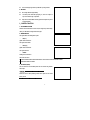
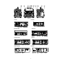
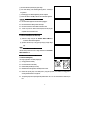
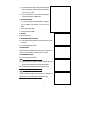
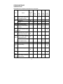
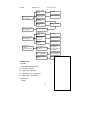
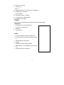
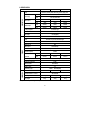
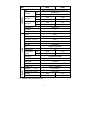
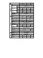
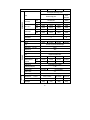
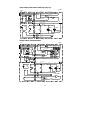
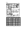
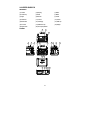
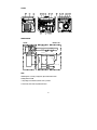
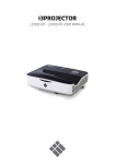
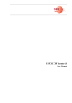
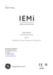
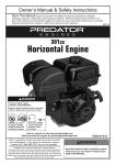
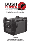
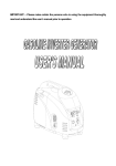
IMPORTANT
Please make certain that persons who are to use this equipment thoroughly read
and understand this user’s manual prior to operation
CONTENTS
1.SAFETY INFORMATION………………………………………………2
2.CONTROL FUNCTION……………………………………………3
3.PRE-OPERATION CHECK……………………………………………6
4.OPERATION…………………………………………………………7
5.PERIODIC MAINTENANCE…………………………………………10
6.TROUBLE SHOOTING………………………………………………13
7.STORAGE…………………………………………………………15
8.SPECIFICATIONS…………………………………………………16
9.WIRING DIAGRAM…………………………………………………21
10.INVERTER GENERATOR…………………………………………………24
1
! WARNING
PLEASE READ AND UNDERSTAND THIS MANUAL COMPLETELY BEFORE OPERATING THE MATCHINE.
─────────────────────────────
───
1 SAFETY INFORMATION
1 EXHAUST FUMES ARE POISONOUS
Never operate the engine in a closed area or it may cause unconsciousness and death within a short time. Operate
the engine in a well ventilated area.
2 FUEL IS HIGHLY FLAMMABLE AND POISONOUS
Always turn off the engine when refueling
Never refuel while smoking or in the vicinity of an open flame.
Take care not to spill any fuel on the engine or muffler when refueling.
If you swallow any fuel, inhale fuel vapor, or allow any to get in your eyes, see your doctor immediately. If any fuel
spills on your skin or clothing, immediately wash with soap and water and change your clothes.
When operating or transporting the machine, be sure it is kept upright. If it tilts, fuel may leak from the carburetor or
fuel tank.
3 ENGINE AND MUFFLER MAY BE HOT
Place the machine in a place where pedestrians or children are not likely to touch the machine.
Avoid placing any flammable materials near the exhaust outlet during operation.
Keep the machine at least 1 m ( 3 ft ) from buildings or other equipment, or the engine may overheat.
Avoid operating the engine with a dust cover.
4 ELECTRIC SHOCK PREVENTION
Never operate the engine in rain or snow.
Never touch the machine with wet hands or electrical shock will occur.
Be sure to ground (earth) the generator.
NOTE:
Use ground (earth) lead of sufficient current capacity.
Ground (earth) Lead
Diameter: 0.12mm (0.005 in)/ampere
EX: 10 Ampere Ù1.2mm (0.055 in)
5 CONNECTION NOTES
Avoid connecting the generator to commercial power outlet.
2
Avoid connecting the generator in parallel with any other generator.
6 BATTERY
No smoking while handing the battery.
The battery emits flammable hydrogen gas, which can explode if
exposed to electric arcing or open flame.
Keep the area well-ventilated and keep open flames/sparks away when
handing the battery
2 CONTROL FUNCTION
1 OIL WARNING SYSTEM
When the oil level falls below the lower level, the engine stops automatically.
Unless you refill with oil, the engine will not start again.
2 ENGINE SWITCH
The engine switch controls the ignition system.
“ON”(run)
Ignition circuit is switched on.
The engine can be started.
“OFF”(stop)
Ignition circuit is switched off.
The engine will not run.
“START”
Starting circuit is switched on.
The starter motor starts.
A EF1600L EF2600L EF4600L EF5200L EF6500L DY1500L DY2500L DY4500L DY5000L DY6500L
B EF6500LE DY5000LX DY6500LX
3 AC SWITCH (N.F.B.)
The AC switch turns off automatically when the load exceeds the generator
rated output.
CAUTION:
Reduce the load to within specified generator rated output if the AC switch
(N.F.B.) turn off.
3
DESCRIPTION
(1) Fuel tank
(2) Fuel tank cap
(3) Fuel cock
(4) Air filter cover
(5) Spark plug
(6) Muffler
(7) Choke lever
(8) AC socket
(9) Engine switch
(10) Ground (earth) terminal
(11) Oil filler cap
(12) Oil drain plug
(13) Recoil starter
(14) Fuel level gauge
(15) Oil warning light
(16) AC switch (N.F.B.)
(17) Voltmeter
(18) DC socket(Option)
(19) DC circuit breaker(Option)
(20) AC output select SW(Option)
(21)Pilot light
3
1
6
9
2
8
10
5
7
4
13
AC
ON
OFF
DC
+
!
ON
12
3
6
9
1
-
OFF
11
2
14
8 10
7
4
13
OFF
ON
FU EL: GA SOLINE(PETROL)
CO MBUSTIB LE: GASO LIN A
CAR BUR ANT: ESSENC E
CAU TION
BE SU RE TO FI LL C RANKCA SE WITH RECOMMENDED O IL BEFO RE USING .
FOR DETA ILED EXPLANATIO N, SEE TH E OWNER'S MANUAL.
DO NO T USE I NDO ORS DU E TO DANGER OF CARBON MON OXIDE POI SONIN G.
ATENTI ON
REMPLI R LE CARTER D'HU ILE RECOMMANDEE AVANT DEMARRAGE.
POU R L'EXPLICATI ON DETA ILLEE, VOI R LE MANUEL D'UTIL ISATEUR.
N E PAS UTI LI SER DAN S UN ENDRO IT FEAME A CAU SE DU RI SQUE D'EMPO ISONN EMENT DU GAZ.
12
11
4
1
6
2
8
AC SOCKET
AC
9
PI LOT LAMP
ENG. SW
.
10
5
3
7
13
DC PROTECTOR
ON
DC
!
OFF
ON
ON
OFF
AC PROTECTOR
12
DY1000L
+
OFF
DC SOCKET
-
11
DY1000LB
AC
!
ON
OFF
ON
-
ON
8
21
OFF
OFF
OFF
+
AC PROTECTOR
9
DC PROTECTOR
PI LOT LAMP
ON
DC
OFF
+
!
ENG. SW.
AC SOCKET
AC
ON
DC
16
DC SOCKET
-
9 16 10 21 18 19
8 19 18 10
DY1500L,DY2500L
DY6500LXT
1
0
ON
OFF
+
9
15
17
16
8
10
9 15
DY4500L,DY5000L
17
16
8
-
18 19 10
DY6500LX
1
0
ON
OFF
+
9
15
17
16
EF1600L, EF2600L
9 15 21
16
8
9
10
15
17
16
8
19
-
18
EF6600LE
9
8
5
15
17
8
16
10
3. PRE-OPERATION CHECK
NOTE:
Pre-operation checks should be made each time the generator is used.
1 CHECK ENGINE FUEL
Check fuel level at fuel level gauge.
If fuel level is low, refill with unleaded automotive gasoline.
Be sure to use the fuel filter screen on the fuel filter neck.
Recommended fuel: Unleaded gasoline.
Fuel tank capacity:
Model
Full
DY1000L, DY1000L1, DY1000LB,DY1500LI,DY1500LBI
EF1600L,EF2600L,DY1500L,DY2500L
4.8 liters
12 liters
DY4500L,DY5000L,DY6500L,DY6500LX, DY6500LXT
22 liters
EF4600L,EF5200L,EF66000L,EF6600LE
22 liters
WARNING:
Do not refill tank while engine is running or hot.
Close fuel cock before refueling with fuel.
Be careful not to admit dust, dirt, water or other foreign objects into fuel.
Wipe off spilt fuel thoroughly before starting engine.
Keep open flames away.
“F” Full, “E” Empty.
2 CHECK ENGINE OIL
Before checking or refilling oil, be sure the generator is put on a stable and level
surface with engine stopped.
Remove oil filler cap and check the engine oil level.
If oil level is below the lower level line, refill with suitable oil to upper level
line. Do not screw in the oil filler cap when checking oil level.
Change oil if contaminated.
Oil capacity
6
Model
Full
DY1000L, DY1000L1, DY1000LB,DY1500LI,DY1500LBI
EF1600L, EF2600LDY1500L, DY2500L
0.6 liters
DY4500L, DY5000L, DY6500L, DY6500LX, DY6500LXT
EF4600L, EF5200L, EF6600L, EF6600LE
0.4 liters
1.1 liters
1.1 liters
Recommended engine oil:
API Service “ SE” or “SF”, if not available, “SD”.
3 GROUND (Earth)
Make sure to ground (earth) the generator.
4. OPERATION
NOTE:
The generator has been shipped without engine oil. Fill with oil or it will not start.
1 STARTING THE ENGINE
NOTE:
Before starting the engine, do not connect the electric apparatus.
Turn the AC switch (N.F.B.) to “OFF”.
1.Turn the fuel cock lever to “ON”.
2.Turn the engine switch to “ON”
3.Turn the choke lever to the “│ │”position. Not necessary if the engine is
warm.
4.Pull the starter handle slowly until resistance is felt. This is the “Compression”
point. Return the handle to its original position and pull swiftly. Do not fully pull
out the rope. After starting, allow the starter handle to return to its original
position while still holding the handle.
5.Warm up the engine.
6.Turn the choke lever back to the operating position.
7.Warm up the engine without a load for a few minutes.
2 USING ELECTRIC POWER
1. AC APPLICATION (SINGLE VOLTAGE TYPE)
7
(a) Check the voltmeter or pilot lamp for proper voltage.
(b) Turn off the switch(es) of the electrical appliance(s) before connecting to
the generator.
(c) Insert the pulg(s) of the electrical appliance(s) into the receptacle.
(d) Turn the AC switch to The “ON” position and turn on the electric apparatus.
CAUTION:
Be sure the electric apparatus is turned off before plugging in.
Be sure the total load is within generator rated output.
Be sure the socket load current is within socket rated current.
To take out power from TWIST LOCK receptacle, insert the plug into
receptacle and turn clockwise to lock it.
2. AC APPLICATION (DUAL VOLTAGE TYPE)
(a) Select the voltage using the AC OUTPUT SELECT SWITCH in
accordance with the electrical appliance.
(b) Operate in the same way as step (a) through step (d) of single voltage
type.
NOTE:
Voltmeter always indicates the lower voltage whichever the AC OUTPUT
SELECT SWITCH is set.
3. DC APPLICATION (option)
This usage is applicable to 12V battery charging only.
110V
(a) Charging instruction for battery
220V
110V
110V
Disconnect the leads for the battery.
Make the battery fluid filler cap loose fully.
Fill distilled water to the upper limit, if the battery fluid is low level.
Measure the specific gravity for the battery fluid by using the hydrometer, and calculate the charging time in
AC OUTPUT
SELECT SW
220V
according with the table shown on right side.
The specific gravity for the fully charged battery shall be within 1.26 to 1.28. It is recommended to confirm every an
hour.
8
(b) Connect between the DC output socket and the battery terminals
using the charging leads. The leads shall be connected making
sure of the (+) and (-) polarity.
(c) The DC circuit protector is to be set to “ON” after confirming the
connection, if the protector is in “OFF” position.
3 STOPPING THE ENGINE
1. Turn off the power switch of the electric apparatus or unplug the
cord from receptacle of the generator. Turn the AC switch to
“OFF”.
2. Turn the engine switch to “OFF”.
3. Turn the fuel cock lever to “OFF”.
4 BATTERY
(for electric starting system)
1. REPLENISHING THE BATTERY FLUID
Check the fluid level. The level should be between the upper and lower
level marks.
Add only distilled water if necessary.
2. BATTERY STORE
Remove the battery and charge it. Store it in a dry place and recharge it once a
month. Do not store the battery in an excessively warm or cold place.
3. RECOMMENDED BATTERY
Recommended battery: 12V/26A·h
NOTE:
Clamp the red wire to the positive (+) terminal and the black wire to the
negative (-) terminal of the battery. Do not reverse these positions.
Be sure the battery is installed on the battery mount tray securely
NOTE:
In order to increase the longevity of your generator it is advantageous to
maintain a minimum load of approximately one third the rated output.
9
5.PERIODIC MAINTENANCE
1) MAINTENANCE CHART
Regular maintenance is most important for the best performance and safe operation.
PreItem
Remarks
Spark
Check condition adjust gap and
Plug
clean. Replace if necessary.
Engine
Check oil level
Oil
Replace
Air Filter
Clean. Replace if necessary.
Fuel Filter
Clean fuel cock filter. Replace if
Check and adjust when engine
Clearance
is cold.
Fuel Line
Check fuel hose for crack or
damage. Replace if necessary.
Exhaust
Check for leakage. Retighten or
System
replace gasket if necessary
Every
3
6
12
check
months
months
months
months
(daily)
or 20 Hr
or 50Hr
or100Hr
or 300Hr
Clean / replace if necessary.
Cooling
Every
1
Check muffler screen.
Carburetor Check choke operation
Every
operation
necessary
Valve
Initial
Check fan damage.
system
Starting
Check recoil starter operation.
system
Decarbon
More frequently if necessary.
i-zation
Fittings /
Check all fittings and fasteners
Fasteners
correct if necessary.
10
2 ENGINE OIL REPLACEMENT
1.
Place the machine on a level surface and warm up the engine for several
minutes. Then stop the engine.
2.
Remove the oil filler cap
3.
Place an oil pan under the engine. Remove the oil drain plug so that the
oil can be completely drained.
4.
Check the oil drain plug, gasket, oil filler cap and O-ring. If damaged
replace.
5.
Reinstall the oil drain plug.
6.
Add engine oil to the upper level.
Recommended engine oil:
API Service “ SE” or “SF”, if not available, “SD”.
CAUTION:
Be sure no foreign material enters the crankcase.
3 AIR FILTER
Maintaining an air cleaner in proper condition is very important. Dirt induced
through improperly installed, improperly serviced, or inadequate elements
damages and wears out engines. Keep the element always clean.
1. Take out the air cleaner, clean it well in kerosene and dry it.
2. After wetting the element by clean engine oil, squeeze it tight by hand.
3. Lastly, put the element in the case and install it securely.
CAUTION:
The engine should never run without the element; excessive piston and/or
cylinder wear may result.
4 CLEANING AND ADJUSTING SPARK PLUG
Standard electrode color: Tan Color
Standard Spark Plug: BPR4ES (NGK)
Spark Plug Gap: 0.7-0.8 mm (0.028-0.031 in)
11
5 FUEL COCK
1.
Stop the engine.
2.
Turn the fuel cock lever to “OFF”.
3.
Clean with solvent.
4.
Wipe off.
5.
Check the gasket. Replace it if damaged.
! WARNING
BE sure the fuel cock cup is tightened securely.
6 FUEL TANK FILTER
Clean with solvent.
Wipe off.
Fuel tank filter.
! WARNING
Be sure the tank cap is tightened securely.
7 MUFFLER SCREEN
! WARNING
The engine and muffler will be very hot after the engine has been run.
Avoid touching the engine and muffler while they are still hot with any part
of your body or clothing during inspection or repair.
1.
Remove the muffler protector and muffler screen.
2.
Clean the carbon deposits out of the muffler screen using a wire brush.
3.
Check the muffler screen. Replace it if damaged.
4.
Install the muffler screen and muffler protector.
Muffler protector
Muffler screen
12
6 TROUBLE SHOOTING
ENGINE TROUBLE SHOOTING
Condition
Probable Cause
Insufficient
compression
Corrective Action
Loose spark plug
Tighten plug properly
Loose cylinder
head bolt
Tighten bolt properly
Damaged gasket
Replace gasket
Fuel systems problems
Engine
won't start
No fuel supplied
to combustion
chamber
Low engine
output
Engine run
erratically
Insufficient
pulling speed for
starting rope
Pull rope sharply
Foreign matter in
fuel tank
Clean tank
Clogged fuel line
Clean fuel line with
dealer's advice
No fuel in tank
Supply fuel
Fuel shutoff not
open
Open valve
Electric systems
problems
Improper
spark
Sufficient
compression
Combustion
chamber supplied
with fuel
Spark plug dirty
with carbon or
wet with fuel
Remove carbon
or wipe up spark
plug
Damaged
spark plug
replace spark
plug
Faulty magneto
Prope
Spark
Improper
adjustment of
carburetor
Insufficient
pulling speed for
starting rope
Improper grade
of fuel used
Consult dealer
Pull rope
sharply
Check fuel
Overloading
Overheating
GENERATOR TROUBLE SHOOTING
13
Check the
working condition
Condition
Probable Cause
Corrective Action
Tripped circuit
breaker
Indicator light ON
No AC output
Reset
Poor Connection
or faulty lead
Check and Repair
Broken
Receptacle
Faulty circuit
breaker
Indicator light OFF
No AC output
Indicator light OFF
No DC output
Output power
available
abnormality exists
Check and Repair
Generator problem
Tripped circuit
breaker
Poor Connection
or faulty DC
power cord
Reset
Check and Repair
Generator
problem
Consult Dealer
Engine RPM set too
hight or low
No load for 60Hz
Set 3780rpm
No load for 50Hz
Set 3150rpm
Loose component
Locate and tighten
Internal generator
problem
Consult Dealer
1 Engine won’t start
1. Fuel systems
No fuel supplied to combustion chamber.
No fuel in tank….Supply fuel.
Clogged fuel line….Clean fuel line.
Foreign matter in fuel cock….Clean fuel cock.
clogged carburetor….Clean carburetor.
2 Engine oil system
Insufficient
14
Oil level is low….Add engine oil.
3
Electrical systems
Poor spark
Spark plug dirty with carbon or wet….Remove carbon or wipe spark plug dry.
Faulty ignition system….Consult dealer.
4. Compression insufficient
Worn out piston and cylinder….Consult dealer.
Loose cylinder head nuts….Tighten nuts properly.
Damaged gasket….Replace gasket.
7. STORAGE
Long term storage of your machine will require some preventive procedures to guard against deterioration.
1 DRAIN THE FUEL
1.
Drain the fuel tank, fuel cock, and carburetor float bowl.
2.
A cup of SAE 10W30 or 20W40 motor oil.
3.
Shake the tank.
4.
Drain off the excess oil.
2 ENGINE
5.
Pour in about one tablespoon of SAE 10W30 or 20W40 motor oil.
6.
Use the recoil starter to turn the engine over several times (with ignition
7.
pull the recoil starter until you feel compression.
8.
Stop pulling.
9.
Clean exterior of the generator and apply a rust inhibitor.
off).
10. Store the generator in a dry, well-ventilated place, with the cover place
over it.
11. The generator must remain in a vertical position.
15
8. SPECIFICATION
MODEL
DY1000L
Type
Max. Output
Rated Output
50Hz
220V,230V, 240V
60Hz
110V,120V,220V,240V,
50Hz
0.95kVA
0.95kVA
0.85kVA
60Hz
1.0kVA
1.0kVA
0.90kVA
50Hz
0.90kVA
0.9kVA
0.80kVA
60Hz
0.95kVA
0.95kVA
0.85kVA
Voltage Regulator
Condenser Type
Power Factor
1.0
DC Output
12V/10A(Option)
Model
MH82
Type
Air-cooled, 4 cycle, OHV, Gasoline Engine
Bore×Stroke
mm×mm
52×38
Displacement
80cc
Max. Output
2.4HP/3600rpm
ENGINE
Fuel
Regular Automobile Gasoline
Fuel tank Capacity
4.5 liters
Rated Continuous
50Hz
6.0 hours
6.0 hours
5.5 hours
Operation
60Hz
5.5 hours
5.5 hours
5.0 hours
Lubricating oil
Engine Oil SD Class or Higher
Lubricating oil Capacity
0.4 liter
Starting System
Recoil Starter
Ignition system
T.C.I.
Spark Plug: Type
DIMENSION
Net dimension
DY1000LB
Brushless, Revolving Field, Self-exciting, 2-poles, Single phase
AC Voltage
GENERATOR
DY1000L1
F6RTC
L×W×H
445×350×365
Overall dimension L×W×H
BPR-4ES(NGK)
415×320×360
440×320×360
460×365×385
Net Weight
28 Kg
26 Kg
30 Kg
Dry Weight
30 Kg
28 Kg
32 Kg
Specifications subject to change without prior notice.
16
MODEL
EF1600L
Type
Brushless, Revolving Field, Self-exciting, 2-poles, Single phase
AC Voltage
GENERATOR
EF2600L
Max. Output
Rated Output
50Hz
220V,230V,240V
60Hz
110V,120V,220V,240V,110/220V,120/240V
50Hz
1.5kVA
2.5kVA
60Hz
1.8kVA
3.0kVA
50Hz
1.3kVA
2.0kVA
60Hz
1.5kVA
2.5kVA
Voltage Regulator
Condenser Type
Power Factor
1.0
DC Output
12V/10A(Option)
Model
MZ175L
Type
Air-cooled, 4 cycle, OHV, Gasoline Engine
Bore×Stroke
mm×mm
68×50
Displacement
171cc
Max. Output
5.5HP/4000rpm
ENGINE
Fuel
Regular Automobile Gasoline
Fuel tank Capacity
12 liters
Rated Continuous
50Hz
12 hours
10 hours
Operation
60Hz
10 hours
8.5 hours
Lubricating oil
Engine Oil SD Class or Higher
Lubricating oil Capacity
0.6 liter
Starting System
Recoil Starter
Ignition system
T.C.I.
Spark Plug: Type
DIMENSION
Net dimension
F6RTC
BPR-4ES(NGK)
L×W×H
510×415×425 mm
Overall dimension L×W×H
525×430×460 mm
Net Weight
40 Kg
43 Kg
Dry Weight
42 Kg
45 Kg
Specifications subject to change without prior notice.
17
MODEL
EF4600L
Type
EF6600L
Max. Output
Rated Output
50Hz
220V,230V,240V
60Hz
110V,120V,220V,240V,110/220V,120/240V
50Hz
4.0kVA
4.5kVA
5.5kVA
5.5kVA
60Hz
4.5kVA
5.2kVA
6.5kVA
6.5kVA
50Hz
3.5kVA
3.8kVA
5.0kVA
5.0kVA
60Hz
4.0kVA
4.5kVA
5.5kVA
5.5kVA
Voltage Regulator
Condenser Type
Power Factor
1.0
DC Output
12V/10A(Option)
Model
MZ300L
Type
Bore×Stroke
ENGINE
MZ360L
mm×mm
78×63
85×63
Displacement
301cc
357cc
Max. Output
10.0HP/4000rpm
12.0HP/4000rpm
Regular Automobile Gasoline
Fuel tank Capacity
22 liters
Rated Continuous
50Hz
10.5 hours
9.2 hours
8.2 hours
8.2 hours
Operation
60Hz
9.0hours
8.5hours
7.0 hours
7.0 hours
Lubricating oil
Engine Oil SD Class or Higher
Lubricating oil Capacity
1.1 liter
Starting System
Recoil Starter
Ignition system
Net dimension
Recoil+Self
T.C.I.
Spark Plug: Type
DIMENSION
MZ360LE
Air-cooled, 4 cycle, OHV, Gasoline Engine
Fuel
EF6600LE
Brushless, Revolving Field, Self-exciting, 2-poles, Single phase
AC Voltage
GENERATOR
EF5200L
F6RTC
BPR-4ES(NGK)
L×W×H
670×510×510 mm
Overall dimension L×W×H
690×530×550 mm
Net Weight
75 Kg
75 Kg
82 Kg
88 Kg
Dry Weight
78Kg
78 Kg
84 Kg
90 Kg
Specifications subject to change without prior notice.
18
MODEL
DY1500L
Type
DY3000L
Max. Output
Rated Output
50Hz
220V,230V,240V
60Hz
110V,120V,220V,240V,110/220V,120/240V
1.5kVA
2.3kVA
3.0 kVA
4.0kVA
4.5kVA
60Hz
1.8kVA
2.8kVA
3.3 kVA
4.5kVA
5.2kVA
50Hz
1.3kVA
2.0kVA
2.5 kVA
3.5kVA
3.8kVA
60Hz
1.5kVA
2.3kVA
2.8 kVA
4.0kVA
4.5kVA
Condenser Type
Power Factor
1.0
DC Output
12V/10A(Option)
Model
HM168F
Type
ENGINE
mm×mm
HM182F
68×45
68×52
82×64
Displacement
163cc
196cc
337cc
Max. Output
5.5HP/4000rpm
Fuel
6.5HP/4000rp
m
1.1HP/4000rpm
Regular Automobile Gasoline
Fuel tank Capacity
12 liters
22 liters
Rated Continuous
50Hz
12 hours
11 hours
10 hours
10.5 hours
9.2 hours
Operation
60Hz
10 hours
9.5 hours
8hours
9.0 hours
8.5 hours
Engine Oil SD Class or Higher
Lubricating oil Capacity
0.6 liter
1.0 liter
Starting System
Recoil Starter
Ignition system
T.C.I.
Spark Plug: Type
Net dimension
DIMENSION
HM168FB
Air-cooled, 4 cycle, OHV, Gasoline Engine
Lubricating oil
DY5000L
50Hz
Voltage Regulator
Bore×Stroke
DY4500L
Brushless, Revolving Field, Self-exciting, 2-poles, Single phase
AC Voltage
GENERATOR
DY2500L
F6RTC
BPR-4ES(NGK)
L×W×H
545×425×440 mm
674×510×532 mm
Overall dimension L×W×H
560×440×460 mm
700×530×550mm
Net Weight
40 Kg
43 Kg
45 Kg
75 Kg
75 Kg
Dry Weight
42 Kg
45 Kg
48 Kg
78 Kg
78 Kg
Specifications subject to change without prior notice.
19
MODEL
DY6500L
DY6500LX
DY6500LXB
DY6500LXT
Revolving Field, Self-exciting, 2-poles,
Type
Brush
Brushless,Single phase
GENERATOR
AC Voltage
Max. Output
Rated Output
50Hz
220V,230V,240V
230/400
60Hz
110V,120V,220V,240V,110/220V,120/240V
240/416
50Hz
5.5kVA
5.5kVA
5.0kVA
5.5kVA
60Hz
6.5kVA
6.5kVA
5.5kVA
6.5kVA
50Hz
5.0kVA
5.0kVA
4.5kVA
5.0kVA
60Hz
5.5kVA
5.5kVA
5.0kVA
5.5kVA
Voltage Regulator
Power Factor
Condenser Type
A.V.R.
1.0
0.8
DC Output
12V/10A(Option)
Model
HM188F
Type
Bore×Stroke
HM188FE
mm×mm
ENGINE
HM188FE
88×64
Displacement
389cc
Max. Output
13.0HP/4000rpm
Regular Automobile Gasoline
Fuel tank Capacity
22 liters
22 liters
14 liters
22 liters
Rated Continuous
50Hz
10.5 hours
9.2 hours
8.2 hours
8.2 hours
Operation
60Hz
9.0hours
8.5hours
7.0 hours
7.0 hours
Lubricating oil
Engine Oil SD Class or Higher
Lubricating oil Capacity
Starting System
1.1 liter
Recoil Starter
Recoil+Self Starter
Ignition system
T.C.I.
Spark Plug: Type
Net dimension
N
HM188FE
Air-cooled, 4 cycle, OHV, Gasoline Engine
Fuel
DIMENSIO
Three phase
F6RTC
BPR-4ES(NGK)
L×W×H
670×510×510mm
910×520×680
699×510×532
Overall dimension L×W×H
700×530×550mm
990×580×820
720×530×550
155Kg
85 Kg
Net Weight
84 Kg
20
87 Kg
Dry Weight
87 Kg
90 Kg
165 Kg
9. WIRING DIAGRAM
Remark : Specifications subject to change without prior notice.
DY1000L DY1000LB DY1000L1
ENGI NE
CONTROL BOX
yel l ow/ gr een
SP
Engi ne
Swi t ch
r ed
bl ack/ whi t e
T. C. I .
ET
yel l ow/ gr een
GENERATOR
r ed
r ed
D
FC
MC
DC pr ot ect or
U1
r ed
REC
PL
MC
SC
U2
yel l ow/ gr een
bl ack
bl ack
Z1
bl ack
yel l ow
Z2
C
yel l ow
DY1500L, DY2500L EF1600L, EF2600L (Single Voltage Type)
C- BOX
E/ G
OS
BLACK
BLUE
BLACK
OSU
SP
YELLOW
YELLOW
BLACK/ WHI TE
BLACK/ WHI TE
RED
RED
PL
ENG. SW
BLACK/ WHI TE
YELLOW/ GREEN
T. C. I .
ET
YELLOW/ GREEN
G/ R
RED
D1
FC
MC
RED
AC SW
U1
RED
REC
V
SC
MC
U2
Z1
Z2
YELLOW/ GREEN
BLACK
BLACK
BLACK
YELLOW
C
YELLOW
21
88 Kg
DY4500L, DY5000L, DY6500L EF4600L, EF5200L(Single Voltage Type)
C- BOX
E/ G
OS
BLACK
BLUE
BLACK
OSU
SP
YELLOW
YELLOW
BLACK/ WHI TE
BLACK/ WHI TE
RED
RED
PL
ENG. SW
BLACK/ WHI TE
YELLOW/ GREEN
T. C. I .
ET
YELLOW/ GREEN
G/ R
RED
D1
AC SW
U1
MC
FC
RED
RED
REC
V
MC
SC
U2
REC
BLACK
YELLOW/ GREEN
BLACK
Z1
BLACK
YELLOW
Z2
C
YELLOW
DY5000LX, DY6500LX , DY6500LXB, EF6600LE
C- BOX
E/ G
OS
BLACK
BLUE
YELLOW
YELLOW
BLACK
OSU
BLACK/ WHI TE
RED
PL
BLACK/ WHI TE
ENG. SW
BLACK/ WHI TE
BLACK BLACK RED RED
WHI TE
WHI TE
OFF
ON
START
YELLOW/ RED
SP
RED
D3
RED
BLACK/ WHI TE
T. C. I .
RED
YELLOW/ RED
FUSE
M
SR
RED/ WHI TE
+
RED
RED
RED
RED/ WHI TE
-
BATTERY
ET
YELLOW/ GREEN
G/ R
RED
D1
FC
MC
U1
AC SW
RED
REC
V
SC
MC
U2
Z1
Z2
RED
RED
REC
BLACK
YELLOW/ GREEN
BLACK
BLACK
BLACK
YELLOW
C
YELLOW
DC SOCKET
RED
DC
D2
BLACK
22
CB
BLACK
DY6500LXT
C- BOX
E/ G
OS
BLACK
BLUE
YELLOW
BLACK
OSU
YELLOW
BLACK/ WHI TE
PL
BLACK/ WHI TE
ENG. SW
BLACK/ WHI TE
RED
BLACK BLACK RED RED
WHI TE
WHI TE
OFF
ON
START
YELLOW/ RED
SP
RED
D3
RED
BLACK/ WHI TE
T. C. I .
RED
YELLOW/ RED
FUSE
M
SR
RED/ WHI TE
+
RED
RED
RED
RED/ WHI TE
-
BATTERY
ET
YELLOW/ GREEN
G/ R
V
U
ai r s wi t c h
V
W
AC socket
N
r ot or
exci t at i on
wi ndi ng
sampl i ng wi ndi ng
t hr ee gr oups of
mai n wi ndi ng
AC socket
A
V
R
DC SOCKET
RED
D2
DC
Symbol
E/G
BLACK
Parts Name
Engine
Symbol
CB
Parts Name
BLACK
Symbol
Parts Name
G/R
Generator
C-BOX
Control box
ENG.SW Engine stop switch
MC
AC winding
AC SW
AC switch
OS
Oil level gauge
SC
Auxiliary winding
V
Voltmeter
OSU
Oil warning unit
FC
Field winding
REC
AC socket
T.C.I.
T.C.I. unit
DC
Charge winding
CB
DC Circuit break
SP
Spark plug
D1
Rectifier
D2
Rectifier
PL
Oil pilot lamp
D3
Rectifier
M
Starter motor
SR
Starter relay
23
10. INVERTER GENERATOR
DESCRIPTION
(1) Fuel tank
(2) Spark plug
(3) Air filter
(4) Fuel tank cap
(5) Handle
(6) Muffler
(7) Engine
(8) Generator
(9) Inverter
(10) Choke lever
(11) Fuel cock
(12) Governor
(13) Recoil starter
(14) Oil drain plug
(15) Oil filler cap
(16) AC socket
(17) MalfunctIion Lamp
(18) Pilot light
(19) Engine switch
(20) Ground (earth) terminal
DY1500LBI
1
2
3
4
5
6
7
8
9
10 11
HOT EXHAUST
ON
!
1.E xhaust ga s contains poisonous
2.Do not use in po orly ven itlated
3.Do not touch with wet hands
4.Po tential dange r of explo sionor ifre
5.St op engine when r efueli ng
6.Ke ep flammable things away
7.Ch eck engine o il before each start.
P lease r ead the u ser's ma nual prio r tooperation
OFF
DY1500LB
A IR CLE A NE R MA N
I TENANCE
CLEAN ELEMENT EVERY 5 0 HOURS (EVERY 1 0 HOURS UNDER
DUSTY CON DIT O
I N).
WASH INH G
I HFL ASH-PO N
I T SO LVENT.
SQUEEZ E DRY, T HEN DIP IN CL EAN ENDINE OIL AND SQUEEZE
OUT EXCESS OIL .
14 15
!
CAUTI ON
ATTENTI ON
CHECK FOR SPI LLED FUEL OR FUEL LEAKS.
ST OP THE ENGI NE BEFORE REFUELI NG.
CONTROLER QU' I L N' Y ANI FUI TE NI ESSENCE REPANDUE SUR
L' APPAREI L. ARRETEZ LE MOTEUR AVANT DE REFAI RE LE PL EI N.
16
17 18 19 20
ON
!
1.Exhaust gas contains poisonous
2.Do not use in poorly ventilated
3.Do not touch with wet hands
4.Potential danger of explosion or fire
5.St op engine when refueling
6.Keep flammable things away
7.Check engine oil before each start.
P lease read the user's manual prior to operation
OFF
DY1500LB
24
12
13
DY1500LI
11
9
1
6
19
4
8
16
20
2
AC
DC
!
18
14
15 17
WIRING DIAGRAM
ENGI NE
CONTROL BOX
yel l ow/ gr een
ENG. SW
SP
r ed
bl ack/ whi t
T. C. I .
ET
yel l ow/ gr een
r ed
r ed
yel l ow/ gr een
GENERATOR
I NVERTER
r ed
socket
PL
bl ack
bl ack
bl ack
yel l ow
mal f unct i on l amp
yel l ow
NOTE:
While the light turn on, showing no output power, please switch off the machine.
Probably problem and settle:
1. Output voltage over to tolerance, Protector works. Try to restart.
2. Short-current, Check circuit, solve problem then restart
25
10
3
7
13
SPECIFICATION
GENERATOR
MODEL
DY1500LI
Type
High frequency permanent magnet generator
Max. Output
1.5kVA
1.2kVA
Rated Output
1.2kVA
1.0kVA
AC Voltage
110/220/240
Frequency
50Hz
60Hz
Phase
ENGINE
60Hz
cosφ=1.0
Degree of Protection
IP23
Model
MH82
Type
Air-cooled, 4 cycle, OHV, Gasoline Engine
Bore×Stroke
mm×mm
52×38
Displacement
80cc
Max. Output
2.4HP/3600rpm
Fuel
Regular Automobile Gasoline
Fuel tank Capacity
4.8 liters
Rated Continuous Operation
6.0 hours
Lubricating oil
Engine Oil SD Class or Higher
Lubricating oil Capacity
0.4 liter
Starting System
Recoil Starter
Ignition system
T.C.I.
Spark Plug: Type
DIMENSION
50Hz
single
Power Factor
DY1500LBI
BPR-4ES(NGK)
Net dimension
L×W×H
445×350×365
Overall dimension
L×W×H
460×365×385
Net Weight
23Kg
24Kg
Dry Weight
25 Kg
26 Kg
Specifications subject to change without prior notice.
26