1
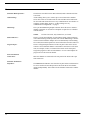
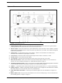
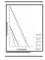
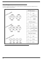
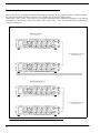
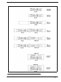
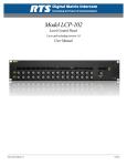
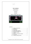
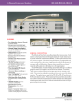
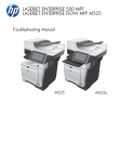
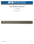
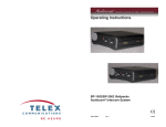
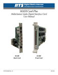
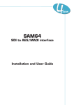
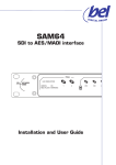
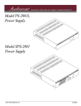
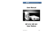
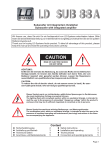
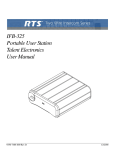
PS-20
Power Supply
User Manual
9350-6786-100 Rev E
April 2009
PROPRIETARY NOTICE
SHIPPING TO THE MANUFACTURER
The product information and design disclosed herein were originated by
and are the property of Bosch Security Systems, Inc. Telex reserves all
patent, proprietary design, manufacturing, reproduction, use and sales
rights thereto, and to any article disclosed therein, except to the extent
rights are expressly granted to others.
All shipments of product should be made via UPS Ground, prepaid (you
may request from Factory Service a different shipment method). Any
shipment upgrades will be paid by the customer. The equipment should
be shipped in the original packing carton. If the original carton is not
available, use any suitable container that is rigid and of adequate size. If
a substitute container is used, the equipment should be wrapped in paper
and surrounded with at least four (4) inches of excelsior or similar
shock-absorbing material. All shipments must be sent to the following
address and must include the Proof of Purchase for warranty repair.
Upon completion of any repair the equipment will be returned via
United Parcel Service or specified shipper, collect.
COPYRIGHT NOTICE
Copyright 2009 by Bosch Security Systems, Inc. All rights reserved.
Reproduction, in whole or in part, without prior written permission from
Bosch is prohibited.
WARRANTY NOTICE
See the enclosed warranty card for further details.
CUSTOMER SUPPORT
Technical questions should be directed to:
Customer Service Department
Bosch Security Systems, Inc.
12000 Portland Avenue South
Burnsville, MN 55337 USA
Telephone: 800-392-3497
Fax: 800-323-0498
Factory Service: 800-553-5992
RETURN SHIPPING INSTRUCTIONS
Customer Service Department
Bosch Security Systems, Inc. (Lincoln, NE)
[email protected]
Telephone: 402-467-5321
Fax: 402-467-3279
Factory Service: 800-553-5992
Factory Service Department
Bosch Security Systems, Inc.
8601 Cornhusker Hwy.
Lincoln, NE 68507 U.S.A.
Attn: Service
This package should include the following:
Part No.
Description
90007854000
US Power Cord
Qty
or
90007854100
Euro Power Cord
1
or
90007854200
UK Power Cord
90107854000
Final Assy, PS-20
1
550006100
Power Cord
1
93506786100
User Manual
1
38110387
Warranty Statement
1
Please include a note in the box which supplies the company name,
address, phone number, a person to contact regarding the repair, the type
and quantity of equipment, a description of the problem and the serial
number(s).
THE LIGHTNING
FLASH AND
ARROWHEAD WITHIN
THE TRIANGLE IS A
WARNING SIGN
ALERTING YOU OF
“DANGEROUS
VOLTAGE” INSIDE THE
PRODUCT.
CAUTION: TO REDUCE THE RISK
OF ELECTRIC SHOCK, DO NOT
REMOVE COVER. NO USERSERVICABLE PARTS INSIDE.
REFER SERVICING TO
QUALIFIED SERVICE
PERSONNEL.
THE
EXCLAMATION
POINT WITHIN THE
TRIANGLE IS A
WARNING SIGN
ALERTING YOU OF
IMPORTANT
INSTRUCTIONS
ACCOMPANYING
THE PRODUCT.
SEE MARKING ON BOTTOM/BACK OF PRODUCT
WARNING:TO PREVENT FIRE OR ELECTRICAL SHOCK HAZARD, DO NOT EXPOSE
THIS PRODUCT TO RAIN OR MOISTURE.
This product is AC only
Table
of
Contents
INTRODUCTION ........................................................................................................................................ 3
Description ................................................................................................................................................................3
Features .....................................................................................................................................................................4
Reference View ..........................................................................................................................................................5
Specifications .............................................................................................................................................................6
Installation .................................................................................................................................................................7
MECHANICAL INSTALLATION .....................................................................................................................................................7
ELECTRICAL INSTALLATION .......................................................................................................................................................7
USING TWO PS-20S AND AUDIO LINKING TWO-WAY COMMUNICATIONS .....................................................................................7
Channel Configuration ............................................................................................................................................10
Termination Impedance ...........................................................................................................................................12
Configuration Diagrams .........................................................................................................................................14
OPERATION AND MAINTENANCE ...................................................................................................... 15
Power-up Indications ..............................................................................................................................................15
Fault Indications .....................................................................................................................................................15
Monitor Output ........................................................................................................................................................15
Mode Selection Switch .............................................................................................................................................15
Termination Impedance Switch ...............................................................................................................................15
Program Input .........................................................................................................................................................16
Maintenance ............................................................................................................................................................16
SAFETY CONSIDERATIONS .......................................................................................................................................................16
ACCESS ...................................................................................................................................................................................16
PS-20 QUICK START ................................................................................................................................ 17
CHAPTER 1
Introduction
Description
The PS-20 is a complete and independent power supply, with the added features of two- and four-channel operation,
monitoring, 2-channel program input, audio linking and three-mode of operation: RTS 2-channel, RTS 4-channel and
Clear-Com mode.
The PS-20 features two channels of communication where both channels are wet, meaning there is power on each channel
(RTS 2-channel mode). In RTS 4-channel mode, the audio signals and DC exist on the same wire, unlike in Clear Com mode,
where the audio and power are on separate lines. Where the PS-15 has power on CH 1 only, power is on both CH 1 and CH 2
on the PS-20.
The PS-20 has a 3-pin XLR (male) connector on the front of the system, where a user can connect to the power supply and
monitor activity on CH 1 or CH 2 (see Figure 1 on page 5). In Clear-Com mode, only channel one (1) is heard. A user station
or beltpack is required to use a headset with this feature.
A single PS-20 Power Supply can power up to 50 user stations (depending on the model and combination - see specifications).
If still more user stations or beltpacks are needed, two PS-20 Power Supplies can be joined together to double the power
capability.
A pair of standard stereo plug connectors are available on the back of the power supply to connect two PS-20 power supplies
through audio linking.
The PGM IN (3-pin XLR female) connector can be used to send Audio to CH 1 and/or CH 2 (for example, a radio station that
users can listen to while they work).
3
Features
Selectable Mode Operation -
The PS-20 is selectable between RTS 2-channel, RTS 4-channel and ClearCom mode.
Audio Linking -
Audio Linking allows you to connect up to two PS-20s with a standard
stereo cable. There is an Audio Link for CH1 and CH2 and an Audio Link
for CH3 and CH4 connection for two way communications. To learn how to
configure Audio Linking, Figure 2, “Audio Linking Two-way
communication configuration.,” on page 8
Monitoring -
The 3-pin XLR Monitoring Output connector allows the user to monitor a
channel or channels. A user station or beltpack is required to use a headset
with this feature.
NOTE:
In Clear-Com mode, only channel one (1) is heard.
Status Indicators -
There is a green status indicator for each channel. Each of these indicators
will remain lit during normal operation, but will turn RED during a channel
current overload condition. Output current is automatically reduced during
an overload, and normal operation is restored when the overload is removed.
Program Input -
There is a Program Input connector on the rear panel. This can be used to
connect a device that both channel 1 and channel 2 can listen to at the same
time (for example, a radio). A Channel Select switch on the front panel
assigns the program to either or both channels. A Level control adjusts the
program level to the intercom channel.
Intercom Channels
Connections -
Intercom channels are connected to the rear panel of the PS-20 with 3-pin
XLR connectors.
Selectable Termination
Impedance -
4
The IMPEDANCE SELECT switch on the rear panel allows each channel to
be set for 200 ohm or 400 ohm operation. Select 200 Ω for each channel
operated independently. Select 400 Ω for each channel connected to another
channel.
Reference View
FIGURE 1.
PS-20 Reference View
1.
Channel Indicator LEDs - Provides a visual indication of the channel DC power. You will see a green LED for
normal operation and a red LED when there is an overload or short circuit.
2.
Monitor Output - Front panel connection for system administrator to listen (can talk as well) to channel 1, channel 2
or both. This is a 3-pin XLR (male). In Clear-Com mode, only channel one (1) is heard. A user station or beltpack is
required to use this feature.
3.
Channel Select - Use the channel switch to select channel 1, channel 2 or both channels. The channel select
determines which channel the Program Input is connected
4.
Level Control - Controls the volume of the program output selected: channel 1, channel 2, or both.
5.
ON/OFF switch - Powers the PS-20 power supply.
6.
AC Connection - This unit accepts any input power in the range of 90 to 240 VAC, 50 to 60 Hz.
7.
Mode Selection Switch - Allows you to select between RTS 2 channel, RTS 4 channel or Clear-Com modes of
operation. For more on Modes of Operation, see “Mode Selection Switch” on page 15.
8.
Termination Impedance Switch - Allows you to select between either 200Ω or 400Ω. 400Ω impedance termination
is most commonly used when connecting two channels on two different PS-20s together.
9.
PGM IN - A 3-pin XLR (female) connection allows the user to put a program source (i.e., a radio) on the channels.
10.
Output Connectors - Channel 1 and Channel 2 Output connectors can be configured to work in RTS-TW 2-channel,
RTS-TW 4-channel, or Clear-Com mode. These are 3-pin XLR (male).
11.
Audio Link CH1&2 and CH3&4 - Connects up to two PS-20s together. For more information, see Figure 2 on
page 8.
12.
Rubber Adhesive Feet - The unit can be rack-mounted or can use feet for desktop usage. For more information on
rack mounting options, see Figure 7 on page 13.
5
Specifications
General
AC Input
Input Voltage:
90 to 240 VAC, 50 to 60 Hz
Output Voltage:
28 VDC to 32 VDC
Output Current:
1.80 Amps Maximum per channel
Termination Impedance:
Selectable 200 Ω / 400 Ω
< 0.2 V
Program Input Levels:
Nominal +2 dBu
Balanced, High Impedance >10 kΩ
Two-Wire Output Levels:
Nominal 30 VDC
Unbalanced, selectable 200 Ω / 400 Ω
Monitor Output:
Nominal Gain of 0 dB for 1000 mVRMS input level on the program input. 30
VDC nominal, 100 mA maximum.
Audio Link
Connections
Common for Audio and DC
30 VDC and Mixed Audio Channel 1
30 VDC and Mixed Audio Channel 2
Type: 3-pin XLR male (RTS 4-channel Mode)
Common for Audio and DC
30 VDC and Mixed Audio Channel 1 or 3
Mixed Audio Channel 2 or 4
Type: 3-pin XLR male (Clear-Com Mode)
Common for Audio
30 VDC
Mixed Audio Channel 1 or 2
Program Input
Common
Balanced Audio + Input
Balanced Audio - Input
Audio Link
Input 1/4” Stereo Phono Jack
Tip:
Channel 1
Ring: Channel 2
Sleeve: Ground
Output 1/4” Stereo Phono Jack
Tip:
Channel 3
Ring: Channel 4
Sleeve: Ground
6
Type: 3-pin XLR male (RTS 2-channel Mode)
Pin 1
Pin 2
Pin 3
Common for Audio and DC
30 VDC and Mixed Audio Channel 1
30 VDC and Mixed Audio Channel 2
Pin 1
Pin 2
Pin 3
Common for Audio and DC
30 VDC and Mixed Audio Channel 1
Mixed Audio Channel 2
Type: 3-pin XLR male (Clear-Com Mode)
Pin 1
Pin 2
Pin 3
Common for Audio
30 VDC
Mixed Audio Channel 1
Environmental
Operating Temperature
0° C - 50° C (32° F to 122 ° F)
Storage
Humidity
Dimensions and Finish
Height
1.72 inches (44 mm) - 1 RU
Width
8.186 inches (207.9 mm)
Weight
Under 5lbs.
Finish
Thermoplastic front panel, Aluminum case, RTS light gray paint - black silk
screen.
Mounting - MCP Style rack kit or (included rubber adhesive feet).
Type: 3-pin XLR female
Pin 1
Pin 2
Pin 3
Monitor Output
0 to 95%, non-condensing
Type: 3-pin XLR male (RTS 2-channel Mode)
Pin 1
Pin 2
Pin 3
Hot
Neutral
Earth Ground
-40° C to 70° C (-40° F to 158° F)
Nominal input 2 dBu with a Gain of 0 dB
Pin 1
Pin 2
Pin 3
Pin 1
Pin 2
Pin 3
Type: 3-pin XLR male (RTS 4-channel Mode)
Ripple:
Pin 1
Pin 2
Pin 3
Type: Universal AC Plug
Approvals and Listings
CE (Comformité Européenne)
UL (Underwriters Laboratory)
CSA (Canadian Standards Associations)
WEEE (Waste Electrical and Electronics Equipment)
ROHS (Restriction of Hazardous Substances)
Installation
Mechanical Installation
The PS-20 Power Supply can be rack mounted or used free standing. For rack configurations, see Figure 7, “Rack Mount
Configurations for the PS-20.,” on page 13. Allow room for cable connections.
Electrical Installation
Connecting Intercom Stations
NOTE: When connecting intercom stations, do not exceed the power supply capacity, either for channel 1, channel 2 or both.
Power supply capacity is graphically illustrated in Figure 3 on page 9.
Connect intercom channels to the output connectors on the rear panel, see Figure 8, “Configuration Diagrams,” on page 14
Using two (2) PS-20s and Audio Linking 2-way communications
When using the Audio Linking configuration, you can connect two (2) PS-20s, to double the load capacity of a channel so
more user stations can be added.
Pin out assignments are as follows:.
Input 1/4” Stereo Phono Jack
Link 1/2
Tip:
Channel 1
Ring: Channel 2
Sleeve: Ground
Output 1/4” Stereo Phono Jack
Link 3/4
Tip:
Channel 3
Ring: Channel 4
Sleeve: Ground
7
FIGURE 2.
Audio Linking Two-way communication configuration.
Program Inputs
A program source may be connected to the PROGRAM INPUT connector on the rear panel. Pin assignments are as follows:
Pin 1 = common/ground
Pin 2 = balanced audio +input
Pin 3 = balanced audio -input
To connect an unbalanced program source, do the following:
1.
Connect pin 3 to pin 1.
2.
Connect program ground to pin 1 and program + to pin 2.
AC Power
Plug the AC power cord into the PS-20 and into an AC mains outlet.
NOTE:
8
The PS-20 is capable to run at 90 to 240 VAC, therefore, operation at 100-110 volts or 200-220 volts does not require
any modification or change. Refer to “Maintenance” on page 16.
FIGURE 3.
A-
Total of two channels
with speaker stations
without call lights
B-
Total of two channesl
with speaker stations
with call lights
C-
One channel speaker
stations without call
lights
D-
One channel speaker
stations with call
lights
E-
One channel with
MRT327 and/or 8
Ohm speaker
Capacity Graph
9
Channel Configuration
The PS-20 is capable of three different modes of operation, RTS-TW 4-channel mode, RTS-TW 2-channel mode, and
Clear-Com 2-channel mode (see Figure 4).
FIGURE 4.
10
Channel Configuration
FIGURE 5.
Intercom and PGM Channel Settings
11
Termination Impedance
When connecting two (2) channels on a PS-20, the termination switch must be set to 400Ω to account for double termination.
By setting the termination impedance at 200Ω over two channels, the power load would decrease to
100Ω (1/200 + 1/200 = 2/200 = 1/100). However, by setting the termination switch to 400Ω when operating over two channels
the impedance to each channel is increased to 200Ω (1/400 + 1/400 = 2/400 = 1/200). For more information on cable wiring,
see Figure 4 on page 10.
FIGURE 6.
12
Termination Impedance Configuration Diagram
FIGURE 7.
Rack Mount Configurations for the PS-20.
13
Configuration Diagrams
FIGURE 8.
14
Configuration Diagrams
CHAPTER 2
Operation and Maintenance
Power-up Indications
Turn on the Power switch. During normal operation, the two CHANNEL STATUS indicators should be lit green.
Fault Indications
If there is a fault on a channel, the CHANNEL STATUS indicator for that channel will turn RED. Possible causes of a fault
include: over voltage, over current, short circuit to ground or severe brown-outs.
Monitor Output
Use the monitor output to monitor channel 1, channel 2, or both channels at the same time.
RTS 4-channel mode - You can only monitor channels 1 and 2.
Clear-Com mode - You can only monitor channel 1.
NOTE:
A user station or beltpack is required to use this feature.
Mode Selection Switch
The PS-20 has a three-position mode selection switch where you can choose the mode in which to operate. You can choose
between RTS-TW 2-channel mode, RTS-TW 4-channel mode or Clear-Com mode. For channel configuration information, see
“Channel Configuration” on page 10.
Termination Impedance Switch
Termination Impedance is necessary when two channels of power are connected (whether between two PS20s, or on the same
unit). When connecting channels, the termination switch should be set at 400Ω, so it equals 200Ω on each channel.
For more information on termination impedance, see “Termination Impedance” on page 12.
15
Program Input
If a program source is connected to the PROGRAM INPUT connector on the back of the PS-20, it may be routed to either
CH1, CH2 or both using the CHANNEL SELECT switch. Use the LEVEL control to adjust the program level on the selected
channel.
NOTE:
In 4-channel mode, the program input is routed to CH2, CH4, or both. For more information, see Figure 5 on
page 11.
Maintenance
Safety Considerations
Service should be performed only by qualified service personnel.
Any adjustment, maintenance, and repair of the opened equipment while any power or voltage is applied should be avoided as
much as possible, and should be carried out only by a skilled person who is aware of the hazard involved.
It is possible for capacitors inside the equipment to still be charged even if the equipment has been disconnected from its
power source.
Access
To get inside the Modle PS-20, remove the screws on the top and bottom covers. Slide covers off toward the back of the unit.
16
CHAPTER 3
PS-20 Quick Start
This quick start is to be used to get your PS-20 unit initially set and running. Further configuration may be needed for more advanced
operation.
On the back of the PS-20 unit:
NOTE: On the front of the PS-20 unit, verify the Power Switch in turned OFF.
1. Connect the supplied power cord to the unit, and then plug the unit into the desired power outlet.
2.
3.
4.
5.
6.
Select the mode in which you want the unit to operate, CC (Clear-Com), RTS/4 (RTS 4-channel), or RTS/2 (RTS 2-channel).
For an overview of the channel modes, see Figure 4, “Channel Configuration,” on page 10.
Select the Termination Impedance, either 200Ω or 400Ω.
Using Figure 8 on page 14, configure the external devices you want to use with the PS-20 unit.
If using an external audio source you want both channel 1 and channel 2 to hear, connect the device using the Program input connection
on the back of the PS-20 unit.
Turn the PS-20 ON.
17