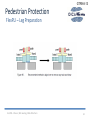
1
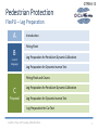
GTR9-8-13
FlexPLI Manual
FlexPLI Preparation before Car Testing
04.09.2013
GTR9-8-13
Pedestrian Protection
FlexPLI – Leg Preparation
A
Introduction
Fitting Flesh
B
current
language
Leg Preparation for Pendulum Dynamic Calibration
Leg Preparation for Dynamic Inverse Test
Fitting Flesh and Covers
C
Proposal
Leg Preparation for Pendulum Dynamic Calibration
Leg Preparation for Dynamic Inverse Test
Leg Preparation for Car Test
IG GTR9 – Phase 2, 8th meeting, OICA office Paris
2
GTR9-8-13
Pedestrian Protection
FlexPLI – Leg Preparation
Introduction
• To ensure repeatability and reproducibility of FlexPLI test results certification and
testing shall be carried out always under the same conditions
• Preparation of FlexPLI is only defined in User Manual for
Pendulum Testing (Item 7.3) and for Inverse Testing (Item 8.5)
• Also for car testing the setup of FlexPLI must always be in the same standardized testing
conditions
• Preparation for vehicle testing may not invalidate FlexPLI verification
• Additional proposal for step-by-step procedure for fitting flesh and covers
to FlexPLI
IG GTR9 – Phase 2, 8th meeting, OICA office Paris
3
GTR9-8-13
Pedestrian Protection
FlexPLI – Leg Preparation
Leg Preparation for Pendulum Dynamic Calibration
3.3.5
Fitting flesh
On the day of the test or for certification the flesh covers are fitted over the leg. To simplify the fitting of the flesh
system all the covers should be laid on the bench in reverse order of assembly. Place the large outer cover on the
bench with lettering face down. Lay 6 strips of Velcro tape over with fluffy side down, then place the rubber buffer
sheet assembly 133-5020 over the strips. The large rubber part goes to the top of the leg; this is the opposite end to
where the zipper on the outer cover starts. Adjust the tape so that all the Velcro strips line up with the six markers on
the rubber see Figure 73. Lay Thigh 2 and Leg 2 covers over, with the two knee end inside arrows pointing towards
each other allowing a gap for the knee area then do the same with Thigh 1 and leg 1 covers. Place the leg assembly
onto the laid out flesh covers with thigh (femur) section over thigh covers and leg (tibia) over leg covers with the leg
assembly on its side. Fit the black plastic protective end covers to the ends of the leg with 4x M5 BHCS.
IG GTR9 – Phase 2, 8th meeting, OICA office Paris
4
GTR9-8-13
Pedestrian Protection
FlexPLI – Leg Preparation
Leg Preparation for Pendulum Dynamic Calibration
3.3.5
Fitting flesh
Do up the zippers on Thigh 1 and Leg 1 making sure each zipper is positioned on the side of the leg, in the area of the
shoulder bolts. Turn the leg over and do up the Thigh 2 and Leg 2 zippers making sure these zippers are on the opposite
side to the first. No zipper should be at the back or the front of the leg or it will interfere with the flat surface of the
launcher plate or sustain damage due the impact.
Wrap the rubber buffer assembly tightly around the leg using the six Velcro straps. The thick wider part of the rubber
system fits just above the top of the femur knee block. See Figure 74, there are markers on the rubber showing the exact
position for the Velcro. It is important that the fluffy side of the Velcro is to the outside otherwise the outer cover cannot
be stretched over due to grip from the eye side of the Velcro.
To get a tight fit with the Velcro it is easier to get someone to pull the rubber sheet around the leg while you are locking
the Velcro.
Finally pass any off board wires or disconnect through any holes in the outer cover if applicable and wrap the outer cover
around the leg. The outer cover is zipped up from the bottom of the leg to make zipper fitting easier. If Messring onboard
DAS is being used just one wire will exit the leg just below the knee if that position is used. It may be necessary to cut a
hole for this wire. Once the zipper is completely zipped up lay the zipper Velcro tag over to protect zipper and to prevent
zipper coming undone.
IG GTR9 – Phase 2, 8th meeting, OICA office Paris
5
GTR9-8-13
Pedestrian Protection
FlexPLI – Leg Preparation
Leg Preparation for Pendulum Dynamic Calibration
3.3.5
Fitting flesh
IG GTR9 – Phase 2, 8th meeting, OICA office Paris
6
GTR9-8-13
Pedestrian Protection
FlexPLI – Leg Preparation
Leg Preparation for Pendulum Dynamic Calibration
7.3
Leg Preparation for Pendulum Dynamic Calibration
•
•
Step 1:
Step 2:
•
Step 3:
•
Step 4:
•
Step 5:
•
Step 6:
•
Step 7:
Check the eight M8 set screws shown in Figure 88 are tightened to 8 Nm
After 60 vehicle tests remove the knee blue front covers and check the 4x M8 button head screws
attaching the legs are tightened to 8 Nm;
Check the four stop cable clearances passing through the femur are set to 9.1 mm and 10.3 on the tibia.
See Figure 89 a special tool 133-5112 is used for this;
Check knee blocks are aligned to ensure knee is not twisted or in a shear condition before the test.
Using two equal height blocks push down on the back of the knee for y direction and also on one side
of the knee for x direction as shown in Figure 90. A straight edge can be used to double check alignment
after any adjustment on two sides
Check all segment screws and side aluminum shoulder screws are tightened to 3 Nm. The impact covers
would need removal to check front segment screws;
Remove the aluminum launch guide (Figure 47 item 18, Part Nr 133-5103,) U shaped bracket fitted to
the top of the femur along with the black protective cover (Figure 54 item 28, Part Nr 133 - 5516);
Attach the ballast weight (Part Nr 133-8436) as shown in Figure 91 to the top of the femur using two
M8 x 50 long cap head screws;
User Manual Page 86 f.
IG GTR9 – Phase 2, 8th meeting, OICA office Paris
7
GTR9-8-13
Pedestrian Protection
FlexPLI – Leg Preparation
Leg Preparation for Pendulum Dynamic Calibration
7.3
Leg Preparation for Pendulum Dynamic Calibration
•
Step 8:
•
Step 9:
Remove the black protective cover (Part Nr 133 – 5516) from the tibia bottom and attach the
Pivot Hinge (Part Nr 133-8418) as shown in Figure 92 using four M6 x 18 long screws.
See next step in section 7.4 for rig preparation. The checking and adjustment of the pendulum Impact
lock (Part 133–8423) must be done with a bare leg without the suit. Check the Impact block is adjusted
to the specification, fit the suit according to the instructions in section 3.3.5 allowing for the electrical
wires to exit at the end of the Pivot Hinge at the top of the (upside down) leg. The leg is now ready to
be hung on the rig.
User Manual Page 86 f.
IG GTR9 – Phase 2, 8th meeting, OICA office Paris
8
GTR9-8-13
Pedestrian Protection
FlexPLI – Leg Preparation
Leg Preparation for Pendulum Dynamic Calibration
7.5
Running a test
•
Step 1:
•
Step 2:
Hook up the sensors on the Data Acquisition System (DAS) and check the
sensor polarities (Section 2.3.2 and Figure 16) by flexing the leg.
Fit the suit according instruction in section 3.3.5 allowing for the electrical
wires to exit at the end of the Pivot Hinge at the top of the (upside down) leg.
The leg is now ready to be hung on the rig.
Fit the leg to the pivot block on the rig using the M10 Socket Head Shoulder
Screw (SHSS). Route the disconnect wire as required out of the end of the
tibia or below the knee depending on type of DAS and tape up to the rig so
that it does not interfere with the free swing motion of the leg when tested.
If using off board DAS the wires are routed out of the top of the leg.
With the leg hanging down vertically, start up and initiate the DAS and set the
DAS such that the sensors are zeroed to zero sensor output in this position.
Important: The leg sensors are zeroed in the vertical impact position before
lifting to 15 degree above horizontal.
•
Step 3:
•
Step 4:
?
Flexing Leg after alignment
during preparation?
Suit fit already described
in item 7.3 – leg
preparation
User Manual Page 90 f.
IG GTR9 – Phase 2, 8th meeting, OICA office Paris
9
GTR9-8-13
Pedestrian Protection
FlexPLI – Leg Preparation
Leg Preparation for Pendulum Dynamic Calibration
7.5
Running a test
•
Step 5:
•
Step 6:
The leg is lifted up to the release mechanism and held in position using the steel wire rope loop
attached to the ballast weight. The rope has been made so that the angle of the leg before release is 15°
above the horizontal. Check once more the angle with a digital inclinometer on the back of the knee.
The steel rope is tied to the ballast weight via an eye bolt, which can be used for fine height adjustment.
Arm the DAS system and release the leg. The trigger for data collection can be from the accelerometer
on the leg, started manually or from a speed gate. After initial impact the leg will continue to bounce,
where possible the leg should be caught or stopped to prevent this. The springs in the knee and the
elastic response from the rubber flesh create a strong rebound. If there is any doubt about safety allow
the leg to bounce after impact.
If a test is to be repeated the leg should rest for 45 minutes minimum before repeating.
If another flesh set is used the test does not need to wait 45 minutes.
User Manual Page 90 f.
IG GTR9 – Phase 2, 8th meeting, OICA office Paris
10
GTR9-8-13
Pedestrian Protection
FlexPLI – Leg Preparation
Leg Preparation for Dynamic Inverse Test
8.5
Leg Preparation for Dynamic Inverse Test
•
Step 1:
Check the eight M8 set screws shown in Figure 88 are tightened to 8 Nm
•
Step 2:
after 60 vehicle tests remove the knee front covers and check the 4x M8
button head screws attaching the legs are tightened to 8 Nm
•
Step 3:
Check the four stop cable clearances passing through the femur are set to 9.1 mm
and 10.3 on the tibia. See figure 89 a special tool 133-5112 is used for this.
•
Step 4:
Check knee blocks are aligned to ensure knee is not twisted or in a shear condition before the test. Using two
equal height blocks push down on the back of the knee for y direction and also on one side of the knee for x
direction as shown in Figure 90. A straight edge can be used to double check alignment after any adjustment
•
Step 5:
Check all segment screws and side aluminum shoulder screws are tightened to 3 Nm
•
Step 6:
Hook up the sensors on the Data Acquisition System (DAS) and check the sensor polarities (Section 2.3.2 and
figure 16) by flexing the leg
?
Polarity check must not be done
repeatedly before each test
IG GTR9 – Phase 2, 8th meeting, OICA office Paris
User Manual Page 94
11
GTR9-8-13
Pedestrian Protection
FlexPLI – Leg Preparation
Leg Preparation for Dynamic Inverse Test
8.5
Leg Preparation for Dynamic Inverse Test
•
Step 7:
Fit inner flesh system as described in 3.3.5
•
Step 8:
Check all wires are correctly positioned to avoid damage and any exit wires are restrained
•
Step 9:
Fit the outer skin cover.
User Manual Page 94
IG GTR9 – Phase 2, 8th meeting, OICA office Paris
12
GTR9-8-13
Pedestrian Protection
FlexPLI – Leg Preparation
Leg Preparation for Dynamic Inverse Test
8.6
Running a Dynamic Inverse Test
• Step 1:
• Step 2:
• Step 3:
…
…
With the leg hanging down vertically, start up and initiate the DAS and set the
DAS such that the sensors are zeroed to zero sensor output in this position.
Important: The leg sensors are zeroed in the vertical impact position.
Arm the DAS system and release the linear guided impactor. The trigger for data
collection can be from the accelerometer on the leg, contact switch or from a
speed gate
• Step 4:
If a test is to be repeated the leg should rest for 45 minutes minimum before repeating.
If another flesh set is used the test does not need to wait 45 minutes.
User Manual Page 95
IG GTR9 – Phase 2, 8th meeting, OICA office Paris
13
GTR9-8-13
Pedestrian Protection
FlexPLI – Leg Preparation
Leg Preparation for Pendulum Dynamic Calibration
3.3.5
Fitting Flesh an Covers
On the day of the test or for certification the flesh covers are fitted over the leg.
To simplify the fitting of the flesh system all the covers should be laid on the bench in reverse order of assembly.
N3:
N2:
N1:
R2:
R1:
Neoprene, outer cover
Neoprene, second layer *
Neoprene, first layer *
Rubber, second layer
Rubber, first layer
* suffix F = femur part, suffix T = tibia part
Section 11-3-99 of Blue Book: Attachment 99
IG GTR9 – Phase 2, 8th meeting, OICA office Paris
14
GTR9-8-13
Pedestrian Protection
FlexPLI – Leg Preparation
Leg Preparation for Pendulum Dynamic Calibration
3.3.5
Step 1:
Fitting Flesh an Covers
Place the large outer cover (N3) on the bench with lettering face down. Lay 6 strips of Velcro tape over
with fluffy side down, then place the rubber buffer sheet assembly 133-5020 over the strips
(R1, R2 (2sheets), R1). The large rubber part goes to the top of the leg; this is the side where
the hanger for dynamic testing is attached. Adjust the tape so that all the Velcro strips line up with the
six markers on the rubber see Figure 73. Lay Thigh 2 and Leg 2 covers (N2F, N2T) over, with the two knee
end inside arrows pointing towards each other allowing a gap for the knee area then do the same with
Thigh 1 and leg 1 covers (N1F, N1T) .
IG GTR9 – Phase 2, 8th meeting, OICA office Paris
15
GTR9-8-13
Pedestrian Protection
FlexPLI – Leg Preparation
Leg Preparation for Pendulum Dynamic Calibration
3.3.5
Step 2:
Fitting Flesh an Covers
Place the leg assembly onto the laid out flesh covers with thigh (femur) section over thigh covers and
leg (tibia) over leg covers with the leg assembly.
Following position of the rubber and neoprene sheets shall be finally ensured:
• the lower edge of the rubber parts R1 and the femur neoprene parts (N1F, N2F) shall align with
the upper end of the knee block
• the recess of the rubber parts R2 shall align with the upper end of the knee block
• The upper edge of the tibia neoprene parts (N1T, N2T) shall align with the lower end of the
knee block
• The outer cover N3 shall be centered to the leg assembly without hangers and ballast weights
Step 3:
Fit the black plastic protective end covers to the ends of the leg with 4x M5 BHCS for inverse and
car testing.
Step 4:
Do up the zippers on Thigh 1 and Leg 1 making sure each zipper is positioned on the side of the leg, in
the area of the shoulder bolts.
IG GTR9 – Phase 2, 8th meeting, OICA office Paris
16
GTR9-8-13
Pedestrian Protection
FlexPLI – Leg Preparation
Leg Preparation for Pendulum Dynamic Calibration
3.3.5
Fitting Flesh an Covers
Step 5:
Turn the leg over and do up the Thigh 2 and Leg 2 zippers making sure these zippers are on the opposite
side to the first. No zipper should be at the back or the front of the leg or it will interfere with the flat
surface of the launcher plate or sustain damage due the impact.
Step 6:
Wrap the rubber buffer assembly tightly around the leg using the six Velcro straps. The thick wider part
of the rubber system fits just above the top of the femur knee block. See Figure 74, there are markers
on the rubber showing the exact position for the Velcro. It is important that the fluffy side of the Velcro
is to the outside otherwise the outer cover cannot be stretched over due to grip from the eye side of
the Velcro. To get a tight fit with the Velcro it is easier to get someone to pull the rubber sheet around
the leg while you are locking the Velcro.
Step 7:
Finally pass any off board wires or disconnect through any holes in the outer cover if applicable.
For Pendulum testing allowing for the electrical wires to exit at the end of the Pivot Hinge at the top of
the (upside down) leg.
For Inverse testing and car testing check all wires are correctly positioned to avoid damage and any exit
wires are restrained.
IG GTR9 – Phase 2, 8th meeting, OICA office Paris
17
GTR9-8-13
Pedestrian Protection
FlexPLI – Leg Preparation
Leg Preparation for Pendulum Dynamic Calibration
3.3.5
Step 8:
Fitting Flesh an Covers
Wrap the outer cover around the leg. The outer cover is zipped up from the bottom of the leg to make
zipper fitting easier. If Messring onboard DAS is being used just one wire will exit the leg just below the
knee if that position is used. It may be necessary to cut a hole for this wire. Once the zipper is
completely zipped up lay the zipper Velcro tag over to protect zipper and to prevent zipper coming
undone..
IG GTR9 – Phase 2, 8th meeting, OICA office Paris
18
GTR9-8-13
Pedestrian Protection
FlexPLI – Leg Preparation
Leg Preparation for Pendulum Dynamic Calibration
7.3
•
•
•
Step 1:
Step 2:
Step 3:
•
Step 4:
•
Step 5:
•
Step 6:
•
Step 7:
•
Step 8:
Leg Preparation for Pendulum Dynamic Calibration
Check alignment of upper an lower knee covers (133-5304, 133-5305)
Check the eight M8 set screws shown in Figure 88 are tightened to 8 Nm
After 60 vehicle tests remove the knee blue front covers and check the 4x M8 button head screws
attaching the legs are tightened to 8 Nm;
Check the four stop cable clearances passing through the femur are set to 9.1 mm and 10.3 on the tibia.
See Figure 89 a special tool 133-5112 is used for this;
Check knee blocks are aligned to ensure knee is not twisted or in a shear condition before the test.
Using two equal height blocks push down on the back of the knee for y direction and also on one side
of the knee for x direction as shown in Figure 90. A straight edge can be used to double check alignment
after any adjustment on two sides
Check all segment screws and side aluminum shoulder screws are tightened to 3 Nm. The impact covers
would need removal to check front segment screws;
Remove the aluminum launch guide (Figure 47 item 18, Part Nr 133-5103,) U shaped bracket fitted to
the top of the femur along with the black protective cover (Figure 54 item 28, Part Nr 133 - 5516);
Attach the ballast weight (Part Nr 133-8436) as shown in Figure 91 to the top of the femur using two
M8 x 50 long cap head screws;
IG GTR9 – Phase 2, 8th meeting, OICA office Paris
19
GTR9-8-13
Pedestrian Protection
FlexPLI – Leg Preparation
Leg Preparation for Pendulum Dynamic Calibration
7.3
Leg Preparation for Pendulum Dynamic Calibration
•
Step 9:
•
Step 10:
•
Step 11:
Remove the black protective cover (Part Nr 133 – 5516) from the tibia bottom and attach the
Pivot Hinge (Part Nr 133-8418) as shown in Figure 92 using four M6 x 18 long screws.
See next step in section 7.4 for rig preparation. The checking and adjustment of the pendulum Impact
lock (Part 133–8423) must be done with a bare leg without the suit. Check the Impact block is adjusted
to the specification,
Fit the flesh and skin covers as described in 3.3.5 allowing for the
electrical wires to exit at the end of the Pivot Hinge at the top of the (upside down) leg.
The leg is now ready to be hung on the rig.
IG GTR9 – Phase 2, 8th meeting, OICA office Paris
20
GTR9-8-13
Pedestrian Protection
FlexPLI – Leg Preparation
Leg Preparation for Pendulum Dynamic Calibration
7.5
Running a test
•
•
Step 1:
Step 2:
•
Step 3:
Hook up the sensors on the Data Acquisition System (DAS)
Fit the leg to the pivot block on the rig using the M10 Socket Head Shoulder
Screw (SHSS). Route the disconnect wire as required out of the end of the
tibia or below the knee depending on type of DAS and tape up to the rig so
that it does not interfere with the free swing motion of the leg when tested.
If using off board DAS the wires are routed out of the top of the leg.
With the leg hanging down vertically, start up and initiate the DAS and set the
DAS such that the sensors are zeroed to zero sensor output in this position.
Important: The leg sensors are zeroed in the vertical impact position before
lifting to 15 degree above horizontal.
IG GTR9 – Phase 2, 8th meeting, OICA office Paris
21
GTR9-8-13
Pedestrian Protection
FlexPLI – Leg Preparation
Leg Preparation for Pendulum Dynamic Calibration
7.5
•
Step 4:
•
Step 5:
•
Step 6:
Running a test
The leg is lifted up to the release mechanism and held in position using the steel wire rope loop
attached to the ballast weight. The rope has been made so that the angle of the leg before release is 15°
above the horizontal. Check once more the angle with a digital inclinometer on the back of the knee.
The steel rope is tied to the ballast weight via an eye bolt, which can be used for fine height adjustment.
Arm the DAS system and release the leg. The trigger for data collection can be from the accelerometer
on the leg, started manually or from a speed gate. After initial impact the leg will continue to bounce,
where possible the leg should be caught or stopped to prevent this. The springs in the knee and the
elastic response from the rubber flesh create a strong rebound. If there is any doubt about safety allow
the leg to bounce after impact.
Detach leg from rig and remove skin and flesh after each test
If a test is to be repeated the leg should rest for 30 minutes minimum before repeating.
If another flesh set is used the test does not need to wait 30 minutes.
IG GTR9 – Phase 2, 8th meeting, OICA office Paris
22
GTR9-8-13
Pedestrian Protection
FlexPLI – Leg Preparation
Leg Preparation for Dynamic Inverse Test
8.5
Leg Preparation for Dynamic Inverse Test
•
Step 1:
Check alignment of upper and lower knee covers (133-5304, 133-5305)
•
Step 2:
Check the eight M8 set screws shown in Figure 88 are tightened to 8 Nm
•
Step 3:
after 60 vehicle tests remove the knee front covers and check the 4x M8
button head screws attaching the legs are tightened to 8 Nm
•
Step 4:
Check the four stop cable clearances passing through the femur are set to 9.1 mm
and 10.3 on the tibia. See figure 89 a special tool 133-5112 is used for this.
•
Step 5:
Check knee blocks are aligned to ensure knee is not twisted or in a shear condition before the test. Using two
equal height blocks push down on the back of the knee for y direction and also on one side of the knee for x
direction as shown in Figure 90. A straight edge can be used to double check alignment after any adjustment
•
Step 6:
Check all segment screws and side aluminum shoulder screws are tightened to 3 Nm
IG GTR9 – Phase 2, 8th meeting, OICA office Paris
23
GTR9-8-13
Pedestrian Protection
FlexPLI – Leg Preparation
Leg Preparation for Dynamic Inverse Test
8.5
Leg Preparation for Dynamic Inverse Test
•
Step 7:
Fit the flesh and skin covers as described in 3.3.5.
Check all wires are correctly positioned to avoid damage and any exit wires are restrained
•
Step 8:
Hook up the sensors on the Data Acquisition System (DAS) as applicable
IG GTR9 – Phase 2, 8th meeting, OICA office Paris
24
GTR9-8-13
Pedestrian Protection
FlexPLI – Leg Preparation
Leg Preparation for Dynamic Inverse Test
8.6
Running a Dynamic Inverse Test
• Step 1:
• Step 2:
• Step 3:
…
…
With the leg hanging down vertically, start up and initiate the DAS and set the
DAS such that the sensors are zeroed to zero sensor output in this position.
Important: The leg sensors are zeroed in the vertical impact position.
Arm the DAS system and release the linear guided impactor. The trigger for data
collection can be from the accelerometer on the leg, contact switch or from a
speed gate
Conduct test
Remove outer skin cover and inner flesh system after each test
• Step 4:
• Step 5:
• Step 6:
If a test is to be repeated the leg should rest for 30 minutes minimum before repeating.
If another flesh set is used the test does not need to wait 30 minutes.
IG GTR9 – Phase 2, 8th meeting, OICA office Paris
25
GTR9-8-13
Pedestrian Protection
FlexPLI – Leg Preparation
Leg Preparation for Car testing
9.2
Leg Preparation for Car testing
• Step 1:
• Step 2:
Check alignment of upper an lower knee covers (133-5304, 133-5305)
Check knee block alignment (no twist, no shear) with straight edge (Figure 90)
Align if necessary
Fit the flesh and skin covers as described in 3.3.5
Check all wires to be in position and restraint
Hang assembled Legform in the launch apparatus
Initiate DAS and zero sensors with leg hanging down vertically in launch apparatus
Conduct test
Remove outer Skin and flesh after each test
• Step 3:
•
•
•
•
Step 4:
Step 5:
Step 6:
Step 7:
If a test is to be repeated the leg should rest for 30 minutes minimum before repeating.
If another flesh set is used the test does not need to wait 30 minutes.
User Manual Page 94
IG GTR9 – Phase 2, 8th meeting, OICA office Paris
26
GTR9-8-13
Pedestrian Protection
FlexPLI – Leg Preparation
Thank you for your attention
On behalf of OICA, provided by:
Winfried Schmitt, BMW
Jan Wilsman, BMW
Thomas Kinsky, OPEL
Klaus Rathje, Daimler
Leonhard Ferdinand, Porsche
IG GTR9 – Phase 2, 8th meeting, OICA office Paris
27
GTR9-8-13
Pedestrian Protection
FlexPLI – Leg Preparation
BACK-UP
IG GTR9 – Phase 2, 8th meeting, OICA office Paris
28
GTR9-8-13
Pedestrian Protection
FlexPLI – Leg Preparation
IG GTR9 – Phase 2, 8th meeting, OICA office Paris
29
GTR9-8-13
Pedestrian Protection
FlexPLI – Leg Preparation
Check alignment of upper an lower knee covers (133-5304, 133-5305)
IG GTR9 – Phase 2, 8th meeting, OICA office Paris
30
GTR9-8-13
Pedestrian Protection
FlexPLI – Leg Preparation
IG GTR9 – Phase 2, 8th meeting, OICA office Paris
31
GTR9-8-13
Pedestrian Protection
FlexPLI – Leg Preparation
IG GTR9 – Phase 2, 8th meeting, OICA office Paris
32