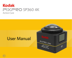
Download User Manual - kodakpixpro.com
Transcript
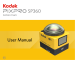
Action Cam
SP360
User Manual
Before You Start
Declaration of Conformity
Responsible Party: JK Imaging Ltd.
Address: JK Imaging Ltd., 17239 So. Main Street, Gardena, CA 90248 USA
JK Imaging Europe, 71 Clarendon Road, Watford, WD17 1DS, UK
Company Website: http://kodakpixpro.com
About this Manual
Thank you for purchasing this product. Please read this manual carefully and keep it in a safe place for future reference.
JK Imaging Ltd. reserves all rights of this document. No part of this published manual may be reproduced, transmitted, transcribed, stored in a retrieval system or
translated into any language or computer language, in any form, by any means, without the prior written permission of JK Imaging Ltd..
All trademarks mentioned in this manual are used for identification purposes only and are properties of their respective owners.
This manual provides you with instructions on how to use your new KODAK PIXPRO Action Cam. Every effort has been made to ensure that the contents of this manual
are accurate; however JK Imaging Ltd. reserves the right to make changes without notice.
Throughout this manual,
indicates the useful information, "
Page number" indicates an introduction to the contents on this page.
1
INDUSTRY CANADA
This device complies with Canadian RSS-210.
This device complies with Industry Canada license-exempt RSS standard (s).Operation is subject to the following two conditions: (1) this device may not cause
interference, and (2) this device must accept any interference, including interference that may cause undesired operation of the device.
Radiation Exposure Statement:
This product complies with the Canadian portable RF exposure limit set forth for an uncontrolled environment and is safe for intended operation as described in this
manual. Additional RF exposure reduction can be achieved if the product can be kept as far as possible from the user body or set the device to lower output power if such
function is available.
For Customers in Europe
This symbol [crossed-out wheel bin WEEE Annex IV] indicates separate collection of electrical waste and electronic equipment in the European countries. Please do
not throw the equipment into domestic refuse. Please use the return and collection systems available in your country for proper, safe disposal of this product.
“CE” mark indicates that this product complies with the European requirements for safety, health, environment and customer protection. “CE” marked cameras are
intended for sales in Europe.
Europe – EU Declaration of Conformity
This device complies with the essential requirements of the R&TTE Directive 1999/5/EC.
The following test methods have been applied in order to prove presumption of conformity with the essential requirements of the R&TTE Directive 1999/5/EC:
- EN 60950-1: 2006+A11:2009 +A1:2010 +A12:2011
Safety of Information Technology Equipment
- EN 50566: 2013
Product standard to demonstrate compliance of radio frequency fields from handheld and body-mounted wireless communication devices used by the general public (30
MHz — 6 GHz)
- EN 62209-2: 2010
Human exposure to radio frequency fields from handheld and body mounted wireless communication devices — Human models, instrumentation, and procedures
Part 2: Procedure to determine the specific absorption rate (SAR) for wireless communication devices used in close proximity to the human body (frequency range of
30 MHz to 6 GHz)
- EN 300 328 V1.8.1 : 2012
Electromagnetic compatibility and Radio spectrum Matters (ERM); Wideband Transmission systems; Data transmission equipment operating in the 2.4 GHz ISM band
and using spread spectrum modulation techniques; Harmonized EN covering essential requirements under article 3.2 of the R&TTE Directive.
- EN 301 489-1 V1.9.2: 2011
Electromagnetic compatibility and Radio Spectrum Matters (ERM); Electro Magnetic Compatibility (EMC) standard for radio equipment and services; Part 1: Common
technical requirements.
- EN 301 489-17 V2.2.1:2012
Electromagnetic compatibility and Radio spectrum Matters (ERM); Electro Magnetic Compatibility (EMC) standard for radio equipment and services; Part 17: Specific
conditions for 2.4 GHz wideband transmission systems and 5 GHz high performance RLAN equipment.
2
For Customers in the U.S.A.
Federal Communication Commission Interference Statement
This device complies with Part 15 of the FCC Rules. Operation is subject to the following two conditions: (1) This device may not cause harmful interference, and (2) this
device must accept any interference received, including interference that may cause undesired operation.
This equipment has been tested and found to comply with the limits for a Class B digital device, pursuant to Part 15 of the FCC Rules. These limits are designed to provide
reasonable protection against harmful interference in a residential installation. This equipment generates, uses and can radiate radio frequency energy and, if not installed
and used in accordance with the instructions, may cause harmful interference to radio communications. However, there is no guarantee that interference will not occur in a
particular installation. If this equipment does cause harmful interference to radio or television reception, which can be determined by turning the equipment off and on, the
user is encouraged to try to correct the interference by one of the following measures:
- Reorient or relocate the receiving antenna.
- Increase the separation between the equipment and receiver.
- Connect the equipment into an outlet on a circuit different from that to which the receiver is connected.
- Consult the dealer or an experienced radio/TV technician for help.
FCC Caution: Any changes or modifications not expressly approved by the party responsible for compliance could void the user's authority to operate this equipment.
This transmitter must not be co-located or operating in conjunction with any other antenna or transmitter.
Radiation Exposure Statement:
This product complies with the FCC portable RF exposure limit set forth for an uncontrolled environment and is safe for intended operation as described in this manual.
Additional RF exposure reduction can be achieved if the product can be kept as far as possible from the user body or set the device to lower output power if such function
is available.
Packaging: Please follow local regulations for the recycling of packaging.
Batteries: Please dispose of used batteries at designated collection centers.
3
Safety Notes
Product Notes:
• Do not disassemble or attempt to repair the product by yourself.
• Do handle the product properly. This product may be damaged if dropped, punctured or crushed.
• Avoid directly touching the lens element, please use professional lens cleaning paper together with lens cleaning agents to wipe the lens and keep the lens clean.
• Do not use corrosive, alcoholic or organic-solvent-containing cleaners to wipe this product.
• Do not use or store this product in high temperature environment.
• Do not expose the lens to strong light sources (e.g. daylight, etc.) for extended periods of time.
• Do not use or store the product in a strong magnetic field environment.
• If the product is quickly transferred from a low temperature environment to a high temperature environment, water condensation may occur in the product due to
physical changes. In this case, it is recommended to wait until the product returns to room temperature before you turn it on.
• If a photo or video cannot be played back due to improper operation by user, the Company shall assume no liability or responsibility for compensation.
• Store the product in a dry and clean environment when you are going to store the product for a long period of time.
Battery Notes:
• Please use a battery that is the same type as the one included.
• If the battery overheats during charging or use, stop charging or use immediately. Turn off the product, remove the battery carefully, and wait until it cools down.
• Please keep the battery contacts clean and dry.
• Please install the battery according to the positive and negative markings on the battery compartment. Never force it into the battery compartment.
• If battery fluid leaks into the product, please contact your retailer. If battery fluid leaks onto your skin, rinse your skin immediately with clean water and seek for medical
attention.
• To prevent the battery from being damaged, do not drop the battery, impact it with heavy objects or scratch it with sharp objects.
• Do not let the battery be in contact with metal objects (including coins) in order to avoid short circuiting, discharging, excessive heating, or possible leakage.
• Do not heat the battery or throw it into a fire in order to avoid a possible explosion.
• Remove the battery if it will be stored for a long period of time.
• Do not store the battery in high temperature environment.
• Using the battery in cold environment will result in a much lower performance.
• Do not attempt to disassemble the battery by yourself.
• Please dispose the battery properly according to local laws and regulations (national or regional).
Memory Card Notes
• The memory card referred to in this manual is a microSD card or microSDHC card.
• Please keep the memory card clean and dry.
• When inserting a memory card, make sure the notch direction of the card matches the notch direction of the memory card mark near the card slot. Do not force the
memory card into the card slot.
• Before using a brand new memory card, please format the memory card first.
• A photo or video taken with the product will be stored in the folder that is automatically generated on the memory card. Do not store photos or videos that are not taken
using the product in these folders in case that the files cannot be normally recognized in playback.
4
• Directly editing the data on memory card is not recommended. Copy the data to your computer disk before editing is recommended.
• Please turn the product off before removing the memory card. Otherwise, the memory card could be damaged.
• When the product is stored for a long period of time, please backup the data on the memory card and remove the memory card.
Other
Notes:
• Do not disconnect the power or turn the product off during firmware updating process. Doing so may cause incorrect data to be written and the product may not power
on later.
• When using your product on an airplane, observe the relevant rules specified by the airline.
• Due to the limitations of manufacturing technology, the LCD may have a few dead or bright pixels. These pixels do no affect the quality of the photos or videos.
• If the LCD screen is damaged, please pay close attention to the liquid crystal in the screen. If any of the following situations arise, kindly take the recommended actions
immediately as indicated below:
1. If liquid crystal comes in contact with your skin, please wipe your skin with a dry cloth, wash with soap thoroughly, and rinse with plenty of clean water.
2. If liquid crystal gets into your eye, flush your eye with plenty of clean water immediately for at least 15 minutes. Please also seek for medical assistance.
3. If liquid crystal is swallowed incautiously, immediately rinse your mouth with clean water and try to induce vomiting. Please also seek for medical assistance.
Waterproof
Notes:
• This product is splashproof for the purposes of daily activities. Before use, please make sure to firmly tighten the lens cover, lock the battery cover, and tightly close the
side cover.
• Any scratches, cracks, or small foreign objects (such as sand or hair) attached to the rubber ring inside of the side cover will affect the efficacy of splashproof function.
Before use, please check whether the waterproofing rubber is damaged or contaminated with a foreign object before closing the side cover. When there is a foreign
object on the waterproofing rubber and its adjacent surfaces, please use a clean, lint-free dry cloth to clean it. If there are any scratches or cracks, immediately go to a
service center for maintenance and obtain a replacement waterproofing rubber.
• Before using the product in water, please make sure you place it inside the waterproof housing first. It can be submerged to no more than 60 meters (196 feet) under the
water at a temperature not exceeding 40 °C. The product can maintain its waterproof performance for up to 4 hours at the depth of 60 meter(196 feet) under the water.
• Do not open the waterproof housing when submerged in water.
• Do not directly open the side cover or battery cover, nor should you remove the lens cover when the product accidentally comes into contact with water. Please turn off
the power and wipe it with a clean, dry, lint-free cloth before opening the battery cover and side cover in order to remove the battery and the memory card.
• When opening the battery cover and the side cover, if there are water droplets on the surfaces located between the interior and the body, please make sure to wipe
them off.
• After using the product in the presence of sand, mud or other foreign matter, please rinse it with clean water (please make sure to firmly tighten the lens cover, lock the
battery cover, and close the side cover tightly before rinsing). After rinsing, wipe it with a clean, dry, lint-free cloth.
Waterproof
/ Dustproof / Shockproof/ Freeze-proof:
• Installing the lens cover, JIS / IEC waterproof grade 5 (IPX5).
• Installing the lens cover, JIS / IEC dustproof grade 6 (IP6X).
• Installing the lens cover, height for shockproof rating is 2.0m.
• Suitable temperature range for freeze proof capability is -10°C and above.
5
Contents
Before You Start.......................................................................................................................................1
Safety Notes.............................................................................................................................................4
Contents...................................................................................................................................................6
Getting Ready..........................................................................................................................................8
Accessories Included.................................................................................................................................................8
Kodak PIXPRO SP360 View.....................................................................................................................................9
Mounting / Removing Lens Cover...........................................................................................................................10
Installing Battery...................................................................................................................................................... 11
Installing Memory Card............................................................................................................................................12
Charging the Battery................................................................................................................................................13
Configuration and Operation..................................................................................................................15
Main Screen Display Introduction............................................................................................................................15
Power On / Off.........................................................................................................................................................16
Start-up for language, date and time.......................................................................................................................16
Introducing the Menu
General Settings
Movie Settings
Still Image Settings
Modes Introduction
........................................................................................................................................17
.................................................................................................................................................................. 18
.................................................................................................................................................................... 19
............................................................................................................................................................... 21
...........................................................................................................................................22
6
V-Eye mode
....................................................................................................................................................................... 23
Wi-Fi mode
......................................................................................................................................................................... 23
Movie mode
........................................................................................................................................................................ 26
Snap Shot Photo mode
Loop recording mode
Time Lapse mode
Burst mode
...................................................................................................................................................... 26
.......................................................................................................................................................... 26
............................................................................................................................................................... 27
......................................................................................................................................................................... 27
About network monitoring.......................................................................................................................28
Account registration.................................................................................................................................................28
Download and use PIXPRO V-Eye..........................................................................................................................31
Using Interfacing....................................................................................................................................44
Micro USB interface.................................................................................................................................................44
Charging......................................................................................................................................................................................... 44
Using an external power supply...................................................................................................................................................... 44
Data transmission........................................................................................................................................................................... 44
Micro HDMI interface...............................................................................................................................................45
Appendices.............................................................................................................................................46
Specifications..........................................................................................................................................................46
Prompts and Warning Messages.............................................................................................................................48
Trouble Shooting.....................................................................................................................................................50
Special Accessories...............................................................................................................................51
7
Getting Ready
Accessories Included
Your product box should contain the product you purchased along with the following accessories. If anything is missing or appears to be damaged, please contact your
retailer. (The AC Adapter style will vary according to the power requirement from different countries or regions. Below picture is for reference only)
Rechargeable Li-ion battery
Glass lens cover
(installed on the product when
leaving factory)
Quick S
Battery charger
AC adapter
Protective cover
Carrying case
tart Gu
ide
Quick start guide
Micro USB cable
Cleaning cloth
STOP
Warranty card
Service card
8
Kodak PIXPRO SP360 View
1
2 3
12
11
10
10
2
Status indicator
4
4
8
9
Glass lens cover
ideo recording button /
V
Shooting button / OK button
3
7
6
5
8
1
NFC mark
5
Menu button / Direction button (lower)
6
ower button / Mode button /
P
Direction button (upper)
7
LCD
8
Microphone
9
Tripod socket
10
Buzzer
11
Side cover
12
Location hole
13
Battery cover
14
Battery cover lock
13
14
9
Mounting / Removing Lens Cover
Removing lens cover:
Mounting lens cover
Turn the lens cover according to the illustrated direction until it separates from the
SP360.
Turn and firmly tighten the lens cover according to the illustrated direction.
The lens cover protects the lens from being damaged (dustproof, shockproof and splashproof). Using the lens cover will not influence the image and video quality.
Before mounting the lens cover, make sure the lens surface is clean and dry. Always use a clean, lint-free dry cloth to clean the lens before shooting or recording so it
will not affect the photo or video quality.
When the SP360 is exposed to extreme temperature differences condensation may form inside of the lens cover. If this happens, remove the lens cover, and clean it
with a soft, dry, lint-free cloth, and then reinstall the lens cover.
If the SP360 will not be used for a period of time, always put the protective cover on it. (as shown in the figure).
10
Installing Battery
1. Open the battery cover
2. Insert the battery
Push the battery cover lock from "LOCK" to "OPEN" along the direction of arrow ① ,
push the battery cover along the direction of arrow ② , and open the battery cover
along the direction of arrow ③ .
Insert the battery into the battery compartment along the direction of arrow ④ (note
the location of the + and - symbols)
4
3
2
1
2
Gently pull the tape upward to remove the battery. When inserting the battery,
please do not fold the tape underneath the battery.
3. Close the battery cover
Align the battery cover over the battery compartment as shown and set it in place
in the direction of arrow ⑤ . Close the battery cover along the direction of arrow ⑥ ,
and push the battery cover lock from "OPEN" to "LOCK" along the direction of arrow
⑦.
5
6
6
7
11
Installing Memory Card
Open the side cover, then insert the memory card into the card slot (note the direction of the memory card gap), push the bottom end of the memory card with a fingertip
into the slot completely, and then close the side cover.
A memory card (microSD / microSDHC) is optional and is not included in the product package. It needs to be purchased separately. Please use an original memory
card which is Class 6 or higher and has a capacity of 4GB to 32GB.
To remove your memory card, open the side cover, gently press the memory card to eject it and remove it carefully.
The product will automatically turn off if the memory card is inserted or extracted when the product is on.
12
Charging the Battery
Please use the battery charger or AC adapter to charge the battery in an ambient temperature ranging from 10 ˚C to 35 ˚C.
Charging the battery with a battery charger:
1. Place the battery into the battery charger according to the direction illustrated. Use the Micro USB cable to connect the battery charger and the AC adapter, and then
plug the AC adapter into an electrical outlet.
2. The indicator light will turn red while charging. The indicator light becomes green means charging is complete.
When charging the battery for the first time or after a long period of storage, please make sure that the charging time is no less than four hours.
Charging the Action Cam with an AC adapter or an external power supply (vehicle power supply, portable power supply, etc):
1. Place the battery into the Action Cam.
2. Use the Micro USB cable to connect the Action Cam to the AC adapter first, then plug the AC adapter into the power outlet. Or, use the Micro USB cable to connect the
Action Cam to an external power supply (vehicle power supply, portable power supply, etc).
3. "Charging ..." shown on the LCD screen indicates the battery charging has begun.
4. The indicator light will become orange while it’s charging. (The Action Cam will automatically shut down after charging is complete.)
Charging will stop after pressing down the
button while charging.
If the Action Cam was set to the Loop recording mode before shutdown, it will automatically start up and start recording when a Micro USB cable is connected to the
Action Cam and an AC adapter (or to an external power supply). (For example: when the Action Cam is connected to a vehicle power supply, it will start and record
automatically when the automobile starts. It will also stop recording, save the files, and power off one minute after the automobile shuts down.)
13
Charging the Action Cam with a computer:
1. Place the battery into the Action Cam.
2. Use the Micro USB cable to connect the Action Cam to a computer (while the computer is on).
3. The indicator light will become orange while charging and will turn off automatically after charging is complete.
14
Configuration and Operation
Main Screen Display Introduction
Main screen displays under Wi-Fi mode
Main screen displays under other modes
2
3
4
5
1
8
1.Mode
7
6
4. Battery status
Movie mode
5. Motion detection (On)
/
Loop recording mode
6. Remaining recording time:
/
/
/
/
/
Time Lapse mode
Number of remaining shots:
none
:("+9999" will be displayed when it exceeds the
none
7. Unfold mode
Burst mode
Dome /
Memory card /
3. Movie size: Internal memory
/
/
/
Photo size:
mm:ss /
maximum available display number) /
Snap Shot Photo mode
2.
hh:mm /
/
/
/
/
/
/
Front /
Seg (Segment) /
Ring
8. Recorded time / photos ("+9999" will be displayed when it exceeds the maximum
available display number)
/
/
15
Power On / Off
Power on:
When the power is off, press and hold the
button for more than one second to turn on the product.
Power off:
When the power is on, press and hold the
button for more than one second to turn off the product.
If the product cannot be powered on / off normally, you can remove the battery from the action cam to force it to power off.
Start-up for language, date and time
1. Press and hold the
button to turn on the product. When starting for the first time, the display will show the date and time setting screen, "Y M D hh:mm:ss".
2. The item to be adjusted will be highlighted with a black background color, press the
3. After adjusting the "minute" value, press the
or
button to adjust the value, press the
button to confirm.
button to enter the Wi-Fi main screen.
16
Introducing the Menu
1. In the main screen (except for Wi-Fi mode), press the
button to enter the first-level menu interface, press the
or
button to select the item, and press the
button to enter the corresponding secondary level menu interface.
In Movie mode/Loop recording mode / Time lapse mode can enter
In Snap Shot Photo mode/Burst mode can enter
Movie Settings and
Still Settings and
General Settings.
General Settings.
2. Press the
or
button to select the item, press the
button to confirm and to enter the tertiary menu interface(highlighted with a black background color).
3. Press the
or
button to select the item, press the
button to confirm and to back to the secondary level menu interface.
4.Select
5.Select
, press the
button to return to the first-level menu interface.
, press the
button to return to the main screen.
First Level Menu
Movie Settings
Still Settings
Unfold mode
Unfold mode
Movie size
Photo size
Power off
White balance
Date / Time
Time Lapse
Loop recording
Secondary Level Menu
General Settings
Volume
Format
Motion detection
Reset settings
Wind cut
FW version
White balance
17
General Settings
Volume
/
Format
Set the volume of the product.
Format can clear all data stored in the memory card or the internal memory.
There are 2 options:
•
Enable
•
Off
When a memory card is inserted, only the card can be formatted. If you need to
format the internal memory, remove the memory card first.
There are 2 options:
Power off
/
•
Off
•
Cancel
, press the
button to start formatting, and return to the
secondary level menu interface after finishing.
Reset settings
There are 2 options:
60 seconds
Confirm
If select
When this function is enabled, if there are no actions taken within a set time frame
(except while recording or connected to Wi-Fi), the product will automatically shut
down.
•
•
Reset settings can recover all product settings to the factory defaults (except for date
and time).
There are 2 options:
Date / Time
•
Confirm
•
Cancel
Set the date and time of the product.
If select
1. The display shows the date and time setting screen, "Y M D hh:mm:ss";
secondary level menu interface after finishing.
, press the
button to start resetting, and return to the
2. The item to be adjusted will be highlighted with a black background color,
press the
or
button to adjust the value, press the
button to
confirm;
3. After adjusting the "minute" value, press the
level menu interface.
button to enter the secondary
FW version
FW version can display the current version. Press the
button to return to the
secondary level menu interface.
When a new version is stored in the memory card, the firmware can be updated.
There are 2 options in the update firmware interface:
Confirm
•
•
Cancel
If select
, press the
button to start updating, and the product will
automatically shut down after finishing.
If the low battery warning is shown, charge the battery before updating the
firmware.
18
Movie Settings
Unfold mode (for Movie mode / Loop recording mode / Time Lapse
mode)
1
* indicates that the selection is unavailable in the Time Lapse modes.
*2 indicates that the selection is unavailable in the Loop recording modes.
Select from several different viewing effects.
If such a movie size is set while in Movie mode, the movie size will be
There are 5 options:
automatically set to
1
•
Dome *
•
Front *
2
•
Seg (Segment) *
Time Lapse modes.
3
* means it does not support electronic image stabilization (EIS).
1
1
•
Ring *
•
Panorama *
(1080P30) when switching to Loop recording or
(480P120) High speed movie:
• The product shoots ultra high speed movies, and plays back with normal
30fps speed, in order to capture visually indistinguishable moments easily.
1
*1 indicates that the default movie size corresponding to this option is
(1440P30).
• The maximum recordable time is 60 seconds, when the time reaches 60
seconds, the product will automatically stop recording.
• The sound cannot be recorded.
•M
otion detection will not work in this mode.
2
* indicates that the default movie size corresponding to this option is
(1080P30).
Movie size (for Movie mode / Loop recording mode / Time Lapse
mode)
Set video resolution.
There are 10 options:
•
1920×1080(30fps)
•
1440×1440(30fps) *
3
•
1072×1072(30fps) *
3
•
1072×1072(30fps)(EIS)
•
1280×960(50fps) *
•
1280×960(30fps)
•
1280×720(60fps) *
•
1280×720(30fps)
•
848×480(60fps) *
•
1
1
1 2
848×480(120fps) *
*
1 2
*
Corresponding table for Movie size and Unfold mode: (O means "available", X
means "not available")
1920×1080(30fps)
X
O
X
X
X
1440×1440(30fps)
O
X
O
O
O
1072×1072(30fps)
O
X
O
O
O
1072×1072(30fps)(EIS)
O
X
O
O
O
1280×960(50fps)
X
O
X
X
X
1280×960(30fps)
X
O
X
X
X
1280×720(60fps)
X
O
X
X
X
1280×720(30fps)
X
O
X
X
X
848×480(60fps)
X
O
X
X
X
848×480(120fps)
X
O
X
X
X
19
Time Lapse (for Time Lapse mode)
2. The display will show the
There are 6 options:
•
1 second
•
2 seconds
•
5 seconds
•
10 seconds
•
30 seconds
•
60 seconds
(960P50) or
1
(720P60) or
4. Press the
(480P60) or
(480P120) cannot be selected.
There are 2 options:
•
10 minutes
(480P60) or
(480P120) cannot be selected when the Motion detection is enabled.
Wind cut refers to the reduction of noise caused by wind.
There are 2 options:
Loop recording mode:
• button again to stop recording and detecting.
Wind cut (for Movie mode / Loop recording mode / Time Lapse
mode)
Loop recording (for Loop recording mode)
5 minutes
2
① Indicates the total time of recording
② Indicates the total time from enable the Motion detection
• Motion detection will not work in this mode.
•
button to activate. If the
3. The product will stop recording when there is no change in the image within
10 seconds. When the image changes again, the product will start recording
automatically, and a new video file will be generated after each pause and
restart.
Time Lapse mode:
• icon. Press the
product detects moving objects, it will automatically start recording
(480P120) cannot be selected.
•
Enable
•
Off
White balance (for Movie mode / Loop recording mode / Time Lapse
mode)
• Motion detection will not work in this mode.
White balance means that the user adjusts the color temperature under different
light sources to ensure that the colors are reproduced correctly.
Motion detection (for Movie mode)
Motion detection means that if the product detects moving objects entering into
the view, it will automatically start recording. During the recording process, if there
is no moving object detected for 10 continuous seconds, the recording will pause
automatically.
There are 2 options:
There are 5 options:
•
Auto white balance
•
Daylight
•
Off
•
Cloudy
•
Enable
•
Fluorescent
•
Underwater
1. Enter the tertiary menu interface of Motion detection, select
, and return to
the main screen.
20
Still Image Settings
White balance(for Snap Shot Photo mode / Burst mode)
Unfold mode(for Snap Shot Photo mode / Burst mode)
White balance means that the user adjusts the color temperature under different
light sources to ensure that the colors are reproduced correctly.
Select from several different viewing effects.
There are 5 options:
There are 5 options:
1
•
Dome *
•
Front *
•
Seg (Segment) *
•
Ring *
•
Panorama *
2
1
1
1
1
.
2
.
* indicates that the default photo size corresponding to this option is
* indicates that the default photo size corresponding to this option is
•
Auto white balance
•
Daylight
•
Cloudy
•
Fluorescent
•
Underwater
Photo size(for Snap Shot Photo mode / Burst mode)
Set photo resolution.
There are 3 options:
•
3264×3264(1:1)
•
2592×1944(4:3)
•
1920×1080(16:9)
Corresponding table for Photo size and Unfold mode: (O means "available", X
means "not available")
O
X
O
O
O
X
O
X
X
X
X
O
X
X
X
21
Modes Introduction
In the main screen display, press the
button to switch modes.
7 modes are available: V-Eye mode
, Wi-Fi mode
Time Lapse mode
Wi-Fi mode
, Burst mode
, Movie mode
, Snap Shot Photo mode
, Loop recording mode
,
.
: THE ACTION CAM MUST BE SET TO Wi-Fi MODE IN ORDER TO BE CONNECTED TO AND OPERATED FROM A PC OR A SMART DEVICE.
If the Action Cam is switched to other modes (V-Eye mode / Movie mode / Snap Shot Photo mode / Loop recording mode / Time Lapse mode / Burst mode) after
Wi-Fi is connected to a PC or a smart device, the Wi-Fi function will automatically turn-off at the Action Cam. IF YOU WANT TO HAVE A CONSISTENT Wi-Fi
CONNECTION BETWEEN THE ACTION CAM AND YOUR DEVICE, PLEASE KEEP THE ACTION CAM SET TO Wi-Fi MODE.
22
V-Eye mode
Network monitoring setting.
For details of operation, see
28.
Wi-Fi mode
Download and Install App
●Smart Device:
Download the App installation package (App name: PIXPRO SP360)
to your smart device from the path below, and install it by following the instructions on the
interface.
For Android devices, search and download the App "PIXPRO SP360" in Google play, and install it by following the instructions on the interface.
For iOS devices, search and download the App "PIXPRO SP360" in App store, and install it by following the instructions on the interface.
●PC:
Download Application "PIXPRO SP360" (for PC) installation package
on the interface.
Americas
/
from the official website, and install it on your computer by following the prompts
Europe
http://kodakpixpro.com/Americas/
support/downloads.php
http://kodakpixpro.com/Europe/
support/downloads.php
Please review the following items before your first connection:
1. Please do not use in places having high intensity magnetic field, electrostatic and electric wave interference (for example near a microwave oven), which may
cause failure in receiving signals.
2. Please do not use Wi-Fi or NFC connection functionality on a plane.
3. To maintain in connection, please keep SP360 within 20 meters (65 feet) without signal shielding interference.
4. SP360 and the smart device can only be connected one to one.
5. SP360 and PC only can be connected one to one.
6. Your smart device operating system version needs to be iOS 7 or higher, or Android 4.0 or higher. iPad mini1 / iPad 2 / iPhone 4s and earlier models (any
systemversions) do not support this App.
7. Your computer operating system version needs to be Mac OS X10.10/10.9/10.8 or Window 8/7.
23
Connect Action Cam to smart device (or PC) with Wi-Fi.
When in Wi-Fi mode, press the
If you wish to disconnect, press the
button to immediately disconnect and exit
button to select
Wi-Fi mode.
button. After pressing the
, press the
or
button to enter the wait for the
connection interface. If you would like to exit WiFi completely, press the
1. Action Cam:
button.
Check SSID (Service Set Identifier) (PIXPRO-SP360_XXXX) and password
(initial password: 12345678) indicated on the label in the battery compartment
button to switch to Wi-Fi
of the Action Cam. In the main interface, press the
mode. The Action Cam will enter the waiting for connection interface after starting
Wi-Fi connection one second later:
4. Smart Device or PC:
When connected via Wi-Fi, you can tap the App icon
start it; or double-click the App icon
If you wish to turn off Wi-Fi, press the
or not to turn off Wi-Fi. After pressing the
press the
button in order to choose whether
or
button to select
button to exit Wi-Fi mode.
2. Smart Device or PC:
Enable Wi-Fi mode, it will automatically search the nearby Wi-Fi hotspots. Select
the one with the same SSID (PIXPRO-SP360_XXXX) and input the password.
3. Action Cam:
When the Wi-Fi connection is successful, enter the Wi-Fi connection interface.
,
/
on the smart device to
on the desktop of the computer
to start it.
5. Action Cam:
When the App is connected to the Action Cam the App connected interface will
appear.
If you wish to disconnect, press the
button to select
, press the
button. After pressing the
or
button to enter the wait for the
connection interface.If you would like to exit WiFi completely, press the
button.
24
Connect Action Cam to smart device with NFC
When recording is started via the App, the Recording interface will appear on
1. Enable NFC mode on your smart device.
the Action Cam.
2. Use your smart device to slightly touch the NFC mark on the Action Cam; if
the smart device has a prompt tone or vibration, it means the connection is
successful.
3. The APP will open automatically on your smart device.
The NFC feature will only be available when your smart device's screen is
unlocked.
If you wish to stop recording, you can do so using the APP or by pressing the
button disconnect. After pressing the
press the
or
button to select
,
button to enter the wait for the connection interface.
After having a successful connection of your smart device with an Action Cam,
if you use a different Action Cam to touch the same smart device, the previous
connection will be replaced.
If the Wi-Fi connection is cut off while recording, the Action Cam will continue to
record and enter the connectionless recording interface. If you wish to stop the
recording, press the
button to select whether or not to stop recording. After
pressing the
button to select
or
, press the
button to enter
the wait for the connection interface.
The Wi-Fi will automatically disconnect if you do not touch the smart device
screen within three minutes after starting to record. However, the Action Cam
will continue recording.
25
Movie mode
Enables video recording. It is suitable for recording in most conditions.
Operation method:
Press the
button to start recording. Repress the
button to stop recording.
Snap Shot Photo mode
Enables photo shooting. It is suitable for recording in most conditions.
Operation method:
Press the
button for photo.
Loop recording mode
Loop recording allows for the recording of independent segments of movies according to selected time length from the beginning of recording. The product will
continually record movies of the length selected until the record button is pressed to end recording. When the memory card is full, the product will overwrite the recorded
files starting from the first movie circularly.
Operation method:
Press the
button to start recording. Repress the
button to stop recording.
Loop recording functionality can only be activated when a memory card is inserted.
26
If the Action Cam was set to the Loop recording mode before shutdown, it will automatically start up and start recording when a Micro USB cable is connected to the
Action Cam and an AC adapter (or to an external power supply). (For example: when the Action Cam is connected to a vehicle power supply, it will start and record
automatically when the automobile starts. It will also stop recording, save the files, and power off one minute after the automobile shuts down.)
Time Lapse mode
Time Lapse enables the recording of an interval of time, and splices the frames together to present a condensed video which usually requires a long period of time to
complete.
Operation method:
Press the
button to start recording. Repress the
button to stop recording.
1
① indicates that the current countdown seconds
Sound cannot be recorded in this mode.
Burst mode
Enables ten photos to be captured continuously before auto pause.
Operation method:
Press the
button, it will stop after 10 photos are taken.
27
About network monitoring
By installing the dedicated application PIXPRO V-Eye
on the smart device, remote monitoring of SP360 can be achieved via a network.
Account registration
Register your account on the official website. The registration URL is as follow:
https://uid.kodakpixpro.com/Americas/cameras/actioncamera/sp360/monitoring/php/index.php
Registration process:
1-1 Account application
UID Accounts
【13B31NSYS3CYZ71Z111A】
1-2 Enter the serial number SN
1-3 Enter the user information
1-4 Remind of successful application
UID (user identity), precautions:
1.Fields marked with * are required;
2.You may find the SN on the battery chamber of the action cam;
3.For safety management, one UID can only be bound with one SN (corresponds to a unique one DV). Never disclose the account information and
UID password to others.
28
Login process:
1.Log in with the registered account.
2.Click [Log In] to enter the [UID Table List] screen:
① to view the UID information under this account;
② to set the UID sharing (enter the recipient’s E-mail address and click [SAVE ALL] to share); the same one SP360 may be connected to 2 smart
devices simultaneously;
③ You may choose to log out a UID.
29
Password changing process:
1. Click on [Lost your password?]
2. Enter the account and verification code
5. Log in and reset the password
3. Send the new password to your E-mail
4. Log in your E-mail and get the
link for password resetting
30
Download and use PIXPRO V-Eye
Download and install APP
Download the App installation package (App name: PIXPRO V-Eye)
to your smart device from the path below, and install it by following the instructions on the
interface.
For Android devices: Search and download the App "PIXPRO V-Eye" in [Google Play], and install it by following the instructions on the interface.
The system version of your smart device shall be Android 4.2 or higher.
For iOS devices: Apps are still under development.
Upon successful installation, an icon
will appear on the screen of the smart device.
31
Operation procedure
Step 1:
Smart device end
Enable the network connection of the smart device.
Step 2:
Smart device end
2-1 Open the App
2-2 Log in with the registered account
2-3 Select a device *1
Inactive device
Account Email
Device Setup
PIXPRO SP360
Set Device Name
S/N-A071234567
Password
PIXPRO SP360
2-5 Connection prompt screen
12:30
PIXPRO SP360
Select connecting device
Log In
2-4 Enter the setting menu
12:30
12:30
12:30
Device Setup
Please check the following conditions of the
DV before connection:
•Please confirm that the picture shooting mode
of the DV is in the “V-Eye Mode” so that the
connection of the APP can be activated
(Figure A).
Enter UID Password
S/N-A071234568
(A)
PIXPRO SP360
S/N-A071234569
•Please confirm that the UID information in the
DV has been cleared if the DV needs to be
re-connected.
PIXPRO SP360
S/N-A071234566
Clear the UID information: DV mode/
V-Eye mode/Menu/Yes
PIXPRO SP360
No Account?
S/N-A071234565
Sign Up Now.
Next
Next
Log In
*1: Select the action cam of which the SN has been registered. For SN, see
28.
32
Step 3:
Action cam end
1. Select the V-Eye mode
2. Press the button
3. Press
or
, and press the
to select sphere
button to confirm.
Round V-Eye
mode (1:1) or square
Front V-Eye
mode (16:9).
again to confirm (turn to connect screen automatically if there is no operation within 5 seconds).
33
Step 4:
Smart device end
4-1If no camera names are
displayed, pull down to refresh.
4-2Select the camera to connect
(PIXPRO-SP360_XXXX).
4-4If connection is successful, the setting of
UID and Wi-Fi hotspot are complete.
4-5 Reminder of
successful setting*4
12:30
12:30
12:30
12:30
Select connecting device
4-3Enter the initial
password (12345678)
12:30
Connection Settings
Select connecting device
Sport Cam Camera Name
PIXPRO SP360_XXXX
PIXPRO SP360_0001
ease enter the WiFi password
•Please disconnect PIXPRO device from phone
(or tablet) then connect PIXPRO device and
phone (or tablet) to Internet to watch the
content of the connected DV.
ABCDEFGH
12345678
PIXPRO-SP360-0002
Setting Successful!
A0712345678
PIXPRO SP360_XXXX
Create UID Password
Show Password
PIXPRO-SP360-0003
*2
Wi-Fi Setting
PIXPRO-SP360-0004
SSID
Connect
nn
PIXPRO-SP360-0005
suggestion
PIXPRO-SP360-0006
q w e
a
?123
suggestion
stion
r
t
y
u
i
d
f
g
h
j
z
x
c
v
b
n m
*2:The user must remember the UID password:
2.1.While sharing the UID, the settings must be shared to the
user to be shared;
2.2.After reinstalling the App, it needs to be entered again.
*3:Touch the
to select your router or directly enter the name
of Wi-Fi SSID and the corresponding password.
*3
o p
s
Enter SSID Password
suggestion
k
l
Save
Next
If connection failed, touch the
to turn back to step 4-2. *5
*5:Causes for connection
failure screen:
Connecting to KODAK Camera Name...
5.1.Whether the connection
between your smart
device and network is
normal;
5.2.Whether the smart
device and password
are correct.
※ SP360 Wi-Fi just can support WPA2 (Wi-Fi Protected Access
II ), but cannot support WPA (Wi-Fi Protected Access).
*4: After setting is completed, the Wi-Fi connection between the
smart device and camera disconnected automatically, and the
camera automatically connects to the router set in *3.
34
Step 5:
Action cam end
When successfully connected to the smart device, the action cam displays:
Connection successful screen. At this point, press the
After pressing
or
button and select
button may erase the action cam’s UID (user identity) information.
, pressing
button may erase all the remote settings (UID/UID password/router
& SSID password).
When failed to connect to the smart device, the action cam displays:
Connection failed [Error1]:
* SSID of the target router not found
* Action cam’s SSID setting incorrect
* Router’s SSID changed
* Router powered off or router failed
* Router too distant to receive signal
35
Connection failed [Error2]:
* SSID of the target router found but connection failed (or action cam’s SSID password setting incorrect)
* Router’s SSID changed
Connection failed:
* Please check whether your router has successfully connected with your internet.
On the connection successful or failed screen, press
button to disconnect. After pressing
or
to select
, pressing
again to enter the waiting for connection screen.
In the V-Eye mode, press
button to interrupt connection directly and exit the V-Eye mode.
36
Step 6:
Smart device end
6-1Select the connection
34.
as set in *3 on
6-2Select the activated
action cam *6
6-3 Monitoring screen
12:30
Select connecting device
12:30
PIXPRO SP360
Active device
PIXPRO SP360_XXXX
S/N-A0712345678
Inactive device
PIXPRO SP360
S/N-A0712345677
PIXPRO SP360 S/N-A0712345676
PIXPRO SP360
S/N-A0712345675
[email protected]
PIXPRO SP360
S/N-A0712345674
*6: The devices successfully set will be moved to the list of [Active device].
Step 7:
Smart device end
7-1 Monitoring screen:
3
At this point, such functions as real-time monitoring, screenshot and motion detection recording are available.
12:30
PIXPRO SP360
4
1.Image output direction adjustment
2.Monitoring screen
3.Menu
4.Device switching
2
5.Screenshot:
Capture the original image sent from the action cam.
1
5
Intelligent devices capture storage paths: SD Card \com.pixpro.veye\Image of Remote veye\Named after
the date of the folder
[email protected]
37
7-2 Size of screenshot and file:
V-Eye mode
Mode
Monitoring range without recording Monitoring range during recording Screenshot size Original size of action cam file
Round V-Eye
1024×1024 (6~8fps)
512×512 (6~8fps)
512×512
1440×1440 (30fps)
Front V-Eye
640×360 (15fps)
640×360 (15fps)
640×360
1920×1080 (30fps)
7-3 Motion detection recording (action cam end)
Save files and record data of the latest period in loop recording mode.
① After switching to the V-Eye mode, the camera automatically enables the motion detection and sends the monitored images to the smart
device.
② Motion detection + 5-minutes loop recording: start recording upon detection of moving object;
If any moving object is detected in the last 10 seconds within 5 minutes after recording, the next 5-minute loop recording starts;
If no moving object is detected in the last 10 seconds within 5 minutes after recording, recording will stop in 5 minutes.
③ When memory capacity is insufficient, earlier files will be deleted automatically.
38
Set the default connection device
The device marked with
is the default connection device. After opening the App, the system will automatically connect to this device.
12:30
12:30
Select connecting device
Select connecting device
Active device
Active device
PIXPRO SP360
PIXPRO SP360
S/N-A071234567
S
S/N-A071234567
PIXPRO SP360 PIXP
PIXPRO SP360 S/N-A071234566
S/N-A
S/N-A071234566
Inactive device
Inactive device
PIXPRO SP360
PIXPRO SP360
S/N-A071234568
S/N-A071234568
PIXPRO SP360 PIXPRO SP360 S/N-A071234565
S/N-A071234565
PIXPRO SP360
PIXPRO
XPRO SP360
Set "@" as your favorite, to
S/N-A071234564
make it your default connection
S/N-A071234564
Change device name
1.Touch the device to be changed.
2.Select [Set Device Name] to modify.
3.Re-enter the name to be changed.
The changed device name will be stored only on the App end, and it will not be saved after re-installing App.
12:30
Select connecting device
Active device
12:30
12:30
Change Device Name
PIXPRO SP360
PIXPRO SP360
Set Device Name
PIXPRO SP360
S/N-A071234567
Inactive device
Active device
My Home-F1
My Home-F1
Enter UID Password
S/N-A071234567
Inactive device
Reset Device (UID Info)
PIXPRO SP360
PIXPRO SP360
S/N-A071234568
S/N-A071234568
Save
av
PIXPRO SP360 S/N-A071234566
PIXPRO SP360
S/N-A071234565
PIXPRO SP360
12:30
Select connecting device
suggestion
1
2
3
q w e
a
S/N-A071234564
?123
PIXPRO SP360 suggestion
ge tion
r
4
t
5
y
6
7
u
i
8
9
0
o p
s
d
f
g
h
j
z
x
c
v
b
n m
,
S/N-A071234566
suggestion
k
l
PIXPRO SP360
S/N-A071234565
PIXPRO
XPRO SP360
SP360
S/N-A071234564
Update Successful!
.
39
Enter password
Touch the device not activated to edit the setting.
Upon setting, the device will be automatically moved to the device list.
12:30
Select connecting device
Active device
12:30
12:30
Enter UID Password
PIXPRO SP360
PIXPRO SP360
Set Device Name
PIXPRO SP360
12345678
Enter UID Password
S/N-A071234567
ABCDEFGH
Inactive device
Reset Device (UID Info)
12345678
PIXPRO SP360
S/N-A071234568
PIXPRO SP360 S/N-A071234566
PIXPRO SP360
S/N-A071234565
PIXPRO SP360
S/N-A071234564
Save
Reset UID information
1.Touch the activated device.
2.Touch [Reset Device (UID Info)] to erase UID information.
After erasing the UID information, the device will be moved to the list of non-activated devices automatically.
12:30
12:30
Select connecting device
Active device
PIXPRO-SP360_0001
Set Device Name
PIXPRO SP360
S/N-A071234567
Inactive device
PIXPRO SP360
S/N-A071234568
PIXPRO SP360 S/N-A071234566
PIXPRO SP360
S/N-A071234565
PIXPRO SP360
S/N-A071234564
12:30
Select connecting device
Inactive device
PIXPRO SP360
Enter UID Password
Reset Device
Device (UID
(UID Info)
Info)
Reset
S/N-A071234567
PIXPRO SP360
S/N-A071234568
PIXPRO SP360
S/N-A071234566
PIXPRO SP360
S/N-A071234565
PIXPRO SP360
S/N-A071234564
Reset Successful!
40
Smart device switching
1.Touch the activated device to establish connection.
to switch to the device list.
2.Touch
3.Select the device to change and touch it to switch to the current device connection.
12:30
Select connecting device
PIXPRO SP360
Active device
12:30
PIXPRO SP360-0001
Active device
PIXPRO SP360
PIXPRO SP360
S/N-A071234567
S/N-A071234567
PIXPRO SP360 -0001
PIXPRO SP360 -0001
S/N-A071234566
S/N-A071234566
Inactive device
Inactive device
PIXPRO SP360
PIXPRO SP360
S/N-A071234568
S/N-A071234568
PIXPRO SP360 PIXPRO SP360 S/N-A071234565
S/N-A071234565
[email protected]
[email protected]
PIXPRO SP360
PIXPRO SP360
S/N-A071234564
S/N-A071234564
Log Out
1.Touch
12:30
12:30
Select connecting device
About
to enter menu.
Click [About] to display the current information.
2.Select [Log Out].
12:30
Menu
PIXPRO-SP360_0004
12:30
12:30
12:30
PIXPRO SP360
Menu
Select connecting device
Log Out
ut
,QDFWLYH'HYLFH
Log Out
Aboutt
About
ou 61$
3,;35263
About
App for Android
v 1.0.0
3,;35263
61$
©2015 by JK Imaging Ltd.
All Rights Reserved.
3,;35263.
61$
For More Information
www.kodakpixpro.com
3,;35263.
61$
3,;35263.
[email protected]
[email protected]
61$
41
Re-set the UID password
The current action cam’s UID-password/SSID /SSID –password has been set.
In any of the following cases, the device will be displayed as not activated:
① Reinstall APP after it is unloaded.
② Reinstall APP after changing smart device.
③ [Reset Device (UID Info)] operation is carried out on the APP end.
Enter password for the device shared from other account
Re-enter password
12:30
Inactive device
Inactive device
PIXPRO SP360
Device Setup
PIXPRO SP360
ABCDEFGH
Enter UID Password
12345678
ABCDEFGH
PIXPRO SP360
S/N-A071234568
12345678
S/N-A071234568
PIXPRO SP360
S/N-A071234567
Set Device Name
PIXPRO SP360
Enter UID Password
PIXPRO SP360
12345678
S/N-A071234567
12:30
12:30
Select connecting device
Enter UID Password
PIXPRO SP360
Select connecting device
12:30
12:30
12345678
PIXPRO SP360
PIXPRO SP360
S/N-A071234566
S/N-A071234566
PIXPRO SP360
PIXPRO SP360
S/N-A071234565
S/N-A071234565
PIXPRO SP360
S/N-A071234564
PIXPRO SP360
S/N-A071234564
Save
Save
The device in the [Active device] list shows connection failure screen:
A
12:30
Select connecting device
Active device
Select connecting device
Active Device
PIXPRO SP360
S/N-A071234567
Connection timeout!
S/N-A071234567
S/N-A071234566
Inactive device
PIXPRO SP360
S/N-A071234568
PIXPRO SP360 S/N-A071234565
12:30
Select connecting device
Active Device
PIXPRO SP360
PIXPRO SP360 B
12:30
• Please check your device & share
Inactive
Device
power
has been started.
• Your device or router settings may
PIXPRO
SP360
have changed, or not completed UID
settings.
S/N-A071234568
3,;35263
UID Password Error!
61$
Inactive
Device
• UID
Password with your DV device
does not match, please re-enter the
correct UID Password.
3,;35263
61$
• You currently cannot connect to a
PIXPRO
SP360
network or
your Internet
connection
has failed.
S/N-A071234566
3,;35263.
• Network transmission congestion
has caused
the network to timeout
PIXPRO
SP360
and disconnect.
S/N-A071234565
PIXPRO SP360
61$
OK
S/N-A071234565
OK
PIXPRO SP360
PIXPRO SP360
PIXPRO SP360
S/N-A071234564
S/N-A071234564
S/N-A071234564
S/N-A071234564
42
Causes for connection failure screen A:
① The action cam cannot be connected to the network (handle as per Error1 or Error2 on the action cam
36)
② Reset operation is carried out on the action cam end.
12:30
12:30
Device Setup
Select connecting device
Inactive device
Please check the following conditions of the
DV before connection:
PIXPRO SP360
•Please confirm that the picture shooting mode
of the DV is in the “V-Eye Mode” so that the
connection of the APP can be activated
(Figure A).
S/N-A071234567
PIXPRO SP360
S/N-A071234568
(A)
PIXPRO SP360
S/N-A071234566
•Please confirm that the UID information in the
DV has been cleared if the DV needs to be
re-connected.
PIXPRO SP360
S/N-A071234565
Re-connect the camera
device. For details, refer
3337.
Clear the UID information: DV mode/
V-Eye mode/Menu/Yes
PIXPRO SP360
S/N-A071234564
Next
Next
Causes for connection failure screen B:
Device’s UID password is changed.
12:30
12:30
Select connecting device
Active device
PIXPRO-SP360_0001
Set Device Name
PIXPRO SP360
S/N-A071234567
Inactive device
PIXPRO SP360
S/N-A071234568
PIXPRO SP360 S/N-A071234566
PIXPRO SP360
S/N-A071234565
PIXPRO SP360
S/N-A071234564
12:30
Select connecting device
Inactive device
12:30
Enter UID Password
PIXPRO SP360
PIXPRO SP360
Enter UID Password
Reset Device
Device (UID
(UID Info)
Info)
Reset
12345678
S/N-A071234567
ABCDEFGH
PIXPRO SP360
S/N-A071234568
12345678
PIXPRO SP360
S/N-A071234566
PIXPRO SP360
S/N-A071234565
PIXPRO SP360
S/N-A071234564
Reset Successful!
Save
43
Using Interfacing
Micro USB interface
Charging
13
Using an external power supply
In case of low battery power, or when a long-term power supply is needed, an external power supply (AC adapter, vehicle power supply, portable power supply or other
power unit) can be used instead of a battery. At this time, the setting of functions, photography, and other operations can be performed.
When powered on, use the Micro USB cable to connect the Action Cam to an external power supply. When connected with an external power supply, "
" will be
displayed on the LCD.
When powered off, use the Micro USB cable to connect the Action Cam to the external power supply. Press and hold the
external power supply, "
button to power on. When connected to an
" will be displayed on the LCD.
Requirements for the external power supply: output power of 5 V, output current of 1 A.
When powered on with a battery inserted, press and hold the
button to shut down and it starts to charge the battery.
If the Action Cam was set to the Loop recording mode before shutdown, it will automatically start up and start recording when a Micro USB cable is connected to the
Action Cam and an AC adapter (or to an external power supply). (For example: when the Action Cam is connected to a vehicle power supply, it will start and record
automatically when the automobile starts. It will also stop recording, save the files, and power off one minute after the automobile shuts down.)
Data transmission
Use the Micro USB cable to connect the Action Cam to a computer and copy files from the Action Cam to the computer.
The steps are as follows:
1. Use the Micro USB cable to connect a computer (the computer should be on) to the Action Cam. During the connection, the Action Cam will display "Connecting ...", and
the computer will automatically detect the Action Cam.
2. Open the Action Cam folder on the computer to copy your files to the computer. After the transmission is completed, please unplug the USB cable in a safe manner
according to the computer's settings.
44
3. The Action Cam will automatically shut down when the Micro USB cable is unplugged.
The Action Cam supports Windows 8/7 and Mac OS X (V10.6.8~V10.10) systems.
If there is a memory card inserted into the Action Cam, only the files in the memory card will be read. If you want to read files in the internal memory, please remove
the memory card before connecting to the computer.
A folder called “SCN” is automatically generated in memory card in the process of video storage; please delete this folder after deleting the video files to save more
space capacity.
Micro HDMI interface
The Action Cam can play back videos and photos on a TV through a Micro HDMI cable.
Set up as follows:
1. Use Micro HDMI cable (to be purchased separately) to connect an HDMI-compliant TV and the Action Cam (the Action Cam and the TV need to be powered on);
2. "Connecting ..." will be displayed on the Action Cam. After the connection is successful, files in the internal memory or the memory card will be displayed on the TV.
3. Press the
or
button to browse the files.
4. When a video file appears on the screen, press the
button to start playback, press the
button to rewind, press the
button to fast forward, and press the
button again to pause playback.
When the Action Cam is connected to the TV while powered off, press and hold the
button to power on.
45
Appendices
Specifications
Design and specifications are subject to change without notice.
Image Sensor
Lens
Anti-Handshake
Type
1/2.33" MOS
Effective Pixels
16.36 Megapixels
Total Pixels
17.52 Megapixels
Focal Length
0.805mm
Equivalent to 35mm film
8.25mm
F number
F2.8
Lens Construction
7 groups 9 elements
Optical Zoom
Fix Focus, 214 Degree
Focusing Range
50cm~∞
Electronic Image Stabilization
Photo size
10M : 3264×3264(1:1)
5M : 2592×1944(4:3)
2M : 1920×1080(16:9)
Movie size
1920×1080(30fps)
1440×1440(30fps)
1072×1072(30fps)
1072×1072(30fps)(EIS)
1280×960(50fps)
1280×960(30fps)
1280×720(60fps)
1280×720(30fps)
848×480(60fps)
High Speed Movie : 848×480(120fps)
Photo
Exif 2.3 (JPEG)
Movie
MP4 [Image: H.264; Audio: AAC(Stereo)]
Number of Recording Pixels
File Format
Modes
Wi-Fi, Movie, Shooting, Loop recording, Time Lapse, Burst
46
Splashproof
Equivalent to JIS/IEC IPX5(Body)
Shockproof
Up to 2m
Dustproof
Equivalent to JIS/IEC (IP6X)
Freeze-proofing
-10°C
LCD
1.0 inch TN LCD
Level Gauge
2-axis
ISO Sensitivity
Auto (100~800)
Exposure Metering Method
Artificial Intelligence AE (AiAE)
Exposure Control Method
Program AE
Burst
Supported
White balance
Auto (AWB), Daylight, Cloudy, Fluorescent, Underwater
Recording Media
Internal Memory: Approx. 8MB
microSD/microSDHC Card (Up to 32GB Support) [MMC Card Not Supported]
Language
English
Interface
USB 2.0 (Micro 5 pin USB) , HDMI (Type D)
Wi-Fi
Supported(802.11b/g/n)
NFC
Supported
Remote Viewfinder
Supported (via smart device)
Power
Rechargeable Li-ion Battery LB-080, 3.6V 1250mAh, In-Action Cam Charging
Shooting Capability (Battery
Performance)
Approx. 350Shots (Based on CIPA Standards) Approx. 160min for Video (@1080p/30fps)
Operation Environment
Temperature: -10 ~ 40°C, Humidity: 0 ~ 90%
Dimensions (W×H×D)
Approx.41.1×50.0×52.1mm (excluding glass lens cover) (Based on CIPA Standards)
Weight
Approx. 103g (Body Only)
47
Prompts and Warning Messages
Message
Description
There are too many files which may cause a delay to power on.
When pressing the
button for shooting, the memory card cannot be accessed
because there are too many folders.
When turning on the product or pressing the
button, the product detects that the
memory card is out of capacity.
When turning on the product or pressing the
button, the product detects that the
internal memory is out of capacity.
Processing mode
After copying the files to the computer,
choose to delete or format.
After copying the files to the computer,
choose to delete or format.
After copying the files to the computer,
choose to delete or format.
Use memory card.
The memory card still cannot be recognized after format.
An error occurs when reading the memory card.
Interruption is encountered during shooting or recording so it cannot be shooting or
recording any further.
Format the memory card.
The internal memory still cannot be recognized after format.
An error occurs when reading the internal memory.
Interruption is encountered during shooting or recording so it cannot be shooting or
recording any further.
Format the internal memory.
When a memory card lower than Class 6 is used to record a HD or above movie, the
writing speed is too slow and recording will not continue.
Please select a Class 6 memory card or
above.
Too many files in the "SCN" folder of the memory card.
Format the memory card.
When the internal memory fails to record Loop recording, the writing speed will slow down
and recording will not continue.
Use memory card.
48
Message
Description
Processing mode
File processing (saving, formatting, etc.) time exceeds 2 seconds.
User should do nothing.
Connecting to the computer USB.
The display will disappear after connection
is successful.
Connecting to the HDMI device.
A warning for low battery before shutting down automatically.
The firmware cannot be updated when power is insufficient.
Charge or replace with a new battery.
Updating firmware.
User should do nothing. The product will
turn off automatically after the update is
completed.
The product will automatically shut down when the battery temperature becomes too high.
Remove the battery carefully when the
product is shut down. The battery will be
good to use again after cooling down.
49
Trouble Shooting
Problem
Product does not turn on
Possible causes
The battery has been depleted.
Solution
Charge the battery.
The battery is installed incorrectly.
Please follow the charging instructions in the manual
to install the battery.
Blurred images
There is dirt on the lens or the glass lens cover.
Clean with a clean, lint-free dry cloth.
Failed to connect Wi-Fi
Wrong password entered.
Please re-enter the password. If you have forgotten
the changed password, you can use the reset function
to restore the password (initial password: 12345678)
Slow Wi-Fi connection
There are too many programs running simultaneously
on the smart device.
Please close other unnecessary programs running on
the smart device.
50
Special Accessories
There are different options of SP-360 accessories available. Accessory bundles vary per retailer. To purchase additional accessories separately, please contact your local
retailer customer service support, or visit http://kodakpixpro.com for more customer service details.
Before using (especially in water or strenuous activity), please pay attention to make sure the product is tightly secured to prevent damage or loss of the product.
Please ensure that the adhesive surface is clean before using double-sided adhesive accessories. Dirt, grease, or other foreign matter will reduce the effectiveness of
the double-sided adhesive. The double-sided adhesive is not easy to remove after sticking. Please take into account the position and angle of sticking before doing it.
After fully assembling the accessories, please make sure the screw and pre-tightening handle are in the proper position and fully secure.
For ease of assembly, please line up the marks on the base and pre-tightening handle per the diagrams below.
Pre-tightening nut
Mark
51
Standard Housing: For use with other accessories when waterproofing is not required
Installation method:
1. First, insert the adapter into the bottom of the standard housing before using the
set screw to tighten.
Adapter
Set screw
2. Place the Action Cam inside the standard housing, and press the lock downward
until it locks tightly.
Lock
52
Waterproof Housing: F
or use with other accessories underwater, in rain, on the seashore, or in other circumstances where waterproofing is
required
Installation method:
1. First, insert the adapter into the bottom of the waterproof
housing before using the set screw for tightening.
Adapter Set screw
2. Remove the Action Cam's glass lens cover , place the Action Cam into the waterproof housing,
put in the anti-fog inserts, and press the lock downward until it locks tightly.
Lock Anti-Fog Inserts
Before using the Action Cam in a wet environment, please be sure to put it inside the waterproof housing first. Also, it should not be submerged to a depth greater
than 60 m (196 feet) underwater.
Anti-fog inserts absorb moisture. Please make sure it is dry before use (heat it in a 150°C oven for around 5 minutes). Each anti-fog insert can be reused up to 4
times.
53
Flat Adhesive Mount:For tacking onto a skateboard or other flat
objects
Curved Adhesive Mount:For tacking onto a helmet or other curved
objects
Installation method:
There are two types of adhesive mounts: flat and curved. You may select based on the shape of the object to be
used.
Both types can be assembled in the same way, take the adhesive mount (flat) as an example:
1. Assemble the adhesive mount or the waterproof housing (
52 /
53).
2. Tie one end of the rope to the adhesive mount and the other end to the standard or waterproof housing.
3. Assemble the adapter, pre-tightening the nut and adhesive mount according to the direction illustrated in the
picture. First press the adapter into the adhesive mount and then rotate and tighten the pre-tightening nut.
4. Tack the double-sided adhesive at the bottom of the adhesive mount to the object to be used.
The double-sided adhesive is disposable. It should be replaced by a new one after being peeled off.
Adapter
Pre-tightening nut
Adhesive Mount
Double-sided adhesive
54
Bar Mount: For mounting on bicycle handlebars, sailing masts, and other tube-like objects
Installation method:
1. Assemble the standard or waterproof housing. (
52 /
53).
2. Set the bar clamp to the handlebar and rotate the screws to tighten.
3. Assemble the adapter, pre-tightening nut and bar clamp in accordance with the
direction illustrated in the picture. First press the adapter into the bar clamp and
then rotate and tighten the pre-tightening nut.
Bar Clamp
Screw
Adapter
Pre-tightening nut
Bar Clamp
55
Suction Cup Mount: For attachment to automotive windshields (or smooth surfaces)
Installation method:
1. Assemble the standard or waterproof housing (
52 /
53).
2. Assemble the adapter, pre-tightening nut and suction mount in accordance with the direction
illustrated in the picture. Press the adapter into the suction mount before rotating and
tightening the pre-tightening nut.
3. First, clean the suction mount and the windshield before attaching
the suction cup to the windshield. Press down the handle to attach it
to the windshield.
Adapter
Pre-tightening nut
Handle
Suction Mount
56
Vented Helmet Strap Mount-A: For mounting on hollow objects like bicycle helmets
Installation method:
1. Align the locator pole on the mount to the locator hole on the Action Cam, and
align the screw on the mount to the Action Cam's tripod socket. Turn the screw
with a coin or similar shape object to tighten.
2. Spread out the band before threading both ends into the helmet. Thread both
ends of the band into the buckle, and then press down on the buckle clamp.
3
Buckle
2
Band
1
Buckle clamp
57
Vented Helmet Strap Mount-B: For mounting on hollow objects like bicycle helmets
Installation method:
1. Align the mount’s locator hole with the Action Cam's locator hole and align the
screw on the mount with the Action Cam's tripod socket. Turn the thumb screw to
tighten.
2. Spread out the band before threading both ends into the helmet. Thread both
ends of the band into the buckle, and then press down on the buckle clamp.
Buckle
Band
Buckle clamp
58
Head Strap Mount: For wearing on one’s head
Installation method:
1. Assemble the standard or waterproof housing (
52 /
53).
2. Insert the base of the standard or waterproof housing to the mount before using the set screw to tighten.
3. Place the band around your head and tighten appropriately.
59
Surfboard Adhesive Mount: To be tacked onto watersports equipment like surf boards
Plane Support (Large)
Plane Support (Small)
Installation method:
1. Assemble the waterproof housing (
53).
2. Tie one end of the rope to the plane support (small), and the other end to the waterproof housing.
3. Assemble the adapter, pre-tightening nut and plane support (large) in accordance with the direction
illustrated in the picture. Press the adapter into the plane support (large) before rotating and tightening the
pre-tightening nut.
4. Tack the double-sided adhesive onto the bottom of the plane support (large) and attach the plane support
(small) to the object to be used.
The double-sided adhesive is disposable. It should be replaced with a new one after being peeled off.
Adapter
Pre-tightening nut
Plane Support (Large)
60
Quick Clip: suitable to be clipped on a belt or harness
Installation method:
1. Align the locator pole on the Quick Clip to the locator hole on the Action Cam, and align the screw of the Quick Clip to the Action Cam tripod mounting hole, and screw it
in to tighten.
2. Clip the clip onto a belt.
Extended Arm:
You can add one or two extended arms (except head strap mount) to each kit, to provide more flexibility to adjust the mounting angle of the Action Cam.
Supported accessories: Flat Adhesive Mount, Curved Adhesive Mount, Bar Mount, Suction Cup Mount, Surfboard Adhesive Mount.
Extended Arm
61
Licensed
Product
The Kodak trademark and trade dress are used under license from Kodak.
© 2014 JK Imaging Ltd. All Rights Reserved.
JK Imaging Ltd., 17239 So. Main Street, Gardena, CA 90248 USA
JK Imaging Europe, 71 Clarendon Road, Watford, WD17 1DS, UK
http://kodakpixpro.com
Ver. 6


