1
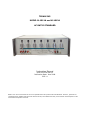
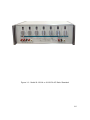
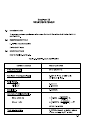
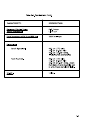
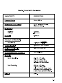
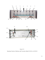
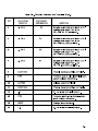
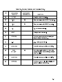
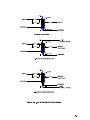
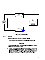
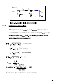
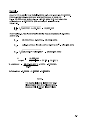
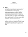
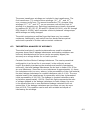
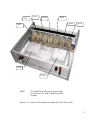
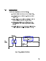
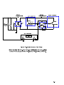
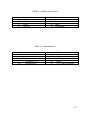
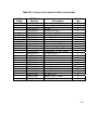
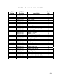
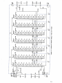
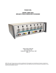
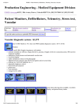
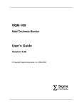
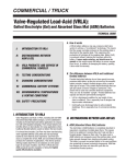
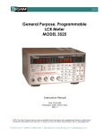
TEGAM INC.
MODEL M-1011A and M-1012A
AC RATIO STANDARD
Instruction Manual
PN# M-1011A-840-01
Publication Date: June 2008
REV. A
TEGAM INC.
MODEL M-1011A and M-1012A
AC RATIO STANDARD
Instruction Manual
PN# M-1011A-840-01
Publication Date: June 2008
REV. A
NOTE: This user’s manual was as current as possible when this product was manufactured. However, products are
constantly being updated and improved. Because of this, some differences may occur between the description in this
manual and the product received.
Figure 1-1. Model M-1011A or M-1012A AC Ratio Standard
1-0
15
1
2
14
13
3
12
4
11
5
10
17
6
7
9
8
18
16
19
20
26
21
25
24
23
22
Figure 3-1.
Operating Controls, Switches, and Terminals, Model M-1011A or M-1012A
3-0
Section III
CONTROLS, SWITCHES, AND TERMINALS
3.1
INTRODUCTION
This section contains functional descriptions of all Model M-1011A and
Model M-1012A controls, switches, and terminals. The location and
purpose of the controls, switches and terminals are the same for the
two AC ratio standard instruments.
3.2
CONTROLS, SWITCHES, AND TERMINALS
All external controls, switches, and terminals of the Model M-1011A
and M-1012A are located on the front and back panels. Their location
is identified by numbers in Figure 3-1, and their function described in
Table 3-1.
Table 3-1. Controls, Switches, and Terminals
1
PANEL/DIAL
MARKING
0 TO X
REFERENCE
DESIGNATOR
S1
2
-1 TO X
S2
3
-1 TO X
S3
KEY
FUNCTION
Decade switch that provides 1
X 10-1 voltage ratio steps from
0 to 10 X 10-1 (x) (11
positions).
Decade switch that provides 1 x
10-2 voltage ratio steps from -1
to 10 x 10-2 (x) (12 positions).
Decade switch that provides 1 x
10-3 voltage ratio steps from 1 to 10 x 10-3 (x) (12
positions).
3-1
Section IV
INSTALLATION
4.1
UNPACKING
No special handling or unpacking procedures are required. After
unpacking, inspect units for any evidence of damage.
4.2
BENCH OPERATION
The AC ratio standard is shipped ready for use as a bench-operated
instrument. A folding support that is attached to the feet under the front
of the instrument may be pulled down to elevate the front of the instrument
for ease of operation.
4.3
RACK MOUNTING
Rack mounting, option 11, (TEGAM part number OPT-11) is available at extra
cost. Option 11 consists of a set of adapter brackets and attaching screws that
permits mounting the AC ratio standard into a standard 19 inch rack. To
prepare the instrument for rack mounting, proceed as follows:
4.4
a.
Remove the six screws that attach the four feet and
folding support to the bottom of the instrument. Retain
the screws, feet and support for future use.
b.
Attach one rack mounting bracket (Part No. 964729-003-1) to
each side of the instrument using two 10-32 X 3/8” flat head
screws (Part No. 964064-263) and three 6-32 x 3/8” flat head
screws (Part No. 964064-028) in each bracket. Note that you will need
to remove the two 6-32 screws securing the side frame to the front
panel to install the new 6-32x3/8” flat head screw.
OPERATING POWER
No operating power is required, however, excitation voltage is required during
operation, refer to Tables 2-1 and 2-2.
4-1/4-2
Section V
OPERATION
5.1
INTRODUCTION
Instructions for operating the AC ratio standard models are presented in this
section. Refer to Section III for descriptions of the operating controls, switches,
and terminals. Refer to Section IV for installation information.
5.2
CONNECTING TO THE AC RATIO STANDARD
Three output circuit configurations are available to the user. All configurations
have the same direct input connection and provide in-phase output voltage.
Choice of output circuit is controlled by which terminals are used. Refer to Figure
5-1 for abbreviated schematics of the three Ratio Standard configurations.
5.3
OPERATION
5.3.1 General
A typical application of the Ratio Standard is shown in Figure 5-2. The output
of the Ratio Standard is compared to the output of the unit under test using
a phase-sensitive null indicator such as a phase angle voltmeter, TEGAM Model
PAV-4. When the in-phase components of the two outputs are exactly equal, the
phase angle voltmeter indicates a null. The input-to-output voltage ratio of the
unit under test may then be read from the settings of the Ratio Standard.
Additional applications are available from the factory.
5-1
CAUTION
Make certain the input voltage does not
contain a dc component. DC currents of
more than a few microamperes will cause
saturation of the input winding. If dc
voltage is accidentally applied to the unit,
degauss the unit as outlined in the
maintenance section, Paragraph 7.3.
c.
Make connections to the OUTPUT and COMMON terminals.
Refer to Figure 5-1, “Standard Configuration”.
CAUTION
Do not apply voltage across the output
terminals.
d.
Turn the input voltage source ON.
e.
Set the standard controls to the desired ratio or to the
setting required to obtain a null. When a null has been
obtained, the FUSE toggle switch may be thrown to the
OUT position to provide a more accurate null measurement.
f.
When a final null is obtained, the input-to-output voltage
ratio of the unit under test may then be read from the
switch settings of the standard.
CAUTION
After the ratio reading has been recorded,
the FUSE toggle switch should be returned
to the IN position for input circuit protection.
5-4
Section VI
THEORY OF OPERATION
6.1
GENERAL
The AC Ratio Standard consists of seven tapped transformer windings and
seven rotary switches. Refer to the Schematic Diagram, Figure 9-1. A
portion of the input voltage is selected from each tapped winding and these
portions are added together to form the output voltage.
The full input voltage is applied across the INPUT and COMMON terminals
and thus across the decade portion of the input (10-1) winding. The
10-1 winding and each of the remaining windings (10-2 through 10-7) are
precisely tapped to provide 12 equal subwindings that will provide 12
precise voltage outputs. S1 has eleven positions. The lower wiper arm
of S1 can select any of eleven voltages from 0 to 1.0 volts in precise
0.1 input voltage ratio steps. The two wiper arms of switch S1, separated
by one position, applies precise 0.1 voltage portions of the 10-1 winding
across the decade portion of the 10-2 winding. The lower wiper arm of S2,
which has 12 positions, selects a -0.01 to 0.1 portion of the input voltage
selected by switch S1. The process continues through the seven windings
until the final and smallest portion is selected by switch S7.
The input winding between the INPUT terminal and the 1.1 terminal
provides a precise 0.1 step-up on the input voltage. The total voltage
between the 1.1 terminal and the COMMON terminal is precisely 1.1 times
the input voltage. The input winding between the COMMON terminal and the
-.1 terminal supplies a voltage with an amplitude precisely 0.1 times the
input voltage and 180 degrees out of phase. The voltage between the
COMMON terminal and the -.1 terminal is therefore -0.1 times the input
voltage.
6-1
The seven transformer windings are included in two transformers. The
first transformer (T1) contains three windings (10-1, 10-2, and 10-3)
on a common toroid core. The second transformer (T2) contains three
windings (10-4, 10-5, and 10-6) on one common core and the final 10-7
winding on a separate core. Switching transients are virtually eliminated
by resistors R1, R3, R5, R7, R9 and R11 (Model M-1011A), and R1 through
R20 (Model M-1012A), which maintain continuity between voltage steps
while settings are being changed.
The switch contacts are multileaf type that have very low contact
resistance. Additionally, each switch has four decks that are paired
and wired in parallel to further reduce contact resistance.
6.2
THEORETICAL ANALYSIS OF ACCURACY
Theoretical analysis of a perfect autotransformer used for stepdown
purposes shows that if leakage inductances and winding resistance are
uniformly distributed and the turns can be accurately tapped, the
accuracy as a voltage divider for no load is perfect.
Consider first the effects of leakage inductance. The most symmetrical
configuration in so far as flux is concerned, is the uniformly wound
toroid. By suitably interleaving the windings and carefully maintaining
uniformity, the total leakage inductances can be kept to under 10% of the
air core inductance. Since the air core inductance is approximately 1/μ times
the inductance with iron core, where μ is the permeability of the core material,
the total leakage inductance to coupled inductance ratio is 1/10μ. The core
material used in the transformers is supermalloy which has a guaranteed
initial permeability of 100,000. The leakage to coupled inductance ratio
is therefore approximately .0001%. Since this figure represents the ratio
of voltage dropped in the leakage inductance to total voltage, the error
in the transformer due to non-distributed leakage inductance will not
exceed this, if the leakage inductance per turn does not vary by more
than ±100%. This condition can be met with suitable techniques of
interleaving the windings.
6-2
Non-distributed winding resistance has much the same effect as nondistributed leakage inductance. If the effects of winding capacities are
neglected, the winding resistance is most important at low frequencies since
the exciting impedance of the transformer is directly proportional to
frequency. Since the exciting impedance is fairly reactive, the voltage
dropped in the winding resistance will be almost in quadrature with the input
and consequently any non-distributed resistance will cause some phase error
as well as magnitude error. The fact that this error voltage is in quadrature
makes the magnitude error extremely small and for all practical purposes
negligible. Typical figures might be .000001% for small ratios and even less
for larger ratios. Phase angles from this cause would be approximately .01
milliradians at low frequencies and small ratios, decreasing for larger ratios.
At higher frequencies distributed capacitance becomes important. It causes
voltage drops in the leakage inductance and winding resistance which are not
uniformly distributed due to the transformer action. Like the effects of
winding resistance, the errors caused by the capacitance are mainly in
quadrature and so cause phase shift at low ratios. Typical values for this
phase shift are:
Less than .05 milliradians for frequencies below 1 kHz and
Ratios above .1 for low voltage – high frequency units.
Less than .05 milliradians for frequencies below 200 Hz and
ratios above .1 for high voltage low frequency units.
Phase angle due to this cause is almost directly proportional to frequency for
any particular ratio down to frequencies where the non-distributed resistance
takes over.
Another source of error is voltage drop due to exciting current in the leads to
the transformer. This effect may be minimized by using heavy connecting
leads or treating the transformer as a four terminal impedance. The internal
wiring of the transformers contributes to this error. These effects are worst
at higher frequencies, above the self-resonant frequencies of the
transformers.
6-3
Section VII
MAINTENANCE
7.1
GENERAL
Since AC Ratio Standards are passive devices, a minimum maintenance
is required. With the exception of cleaning switch contacts, no
maintenance on a regularly scheduled basis is required. Moving parts
are lubricated at the factory and should require no further lubrication.
7.2
SWITCH CONTACTS
During Calibration Intervals, clean switch contacts with a good grade
of solvent such as alcohol or acetone. Relubricate contacts with a small
amount of light lubricant.
7.3
DEGAUSSING
If dc voltage is accidently applied to the input terminals, degauss
the unit as follows:
a.
Connect a 1K resistor in series with the INPUT terminal.
b.
By means of a variac or other suitable voltage control,
apply a 60 Hz signal between the open end of the 1K
resistor and the COM terminal.
c.
Starting with the voltage control at zero, increase
voltage to 40 V rms.
d.
Slowly decrease the voltage to zero. The period of time
to reduce the voltage from 40 V rms to zero should be
between 10 to 15 seconds.
7-1
S106
S105
S104
S103
S102
S107
S101
T102
T101
NOTE:
The Model M-1012A is the same except
for the size of T1 and T2 and the model
number.
Figure 7-1. Location Of Components, Model M-1011A (Top View)
7-2
7.4
CALIBRATION CHECK
Provided that the AC Ratio Standard is kept in a normal laboratory
environment, the unit should only require a calibration check every
three years. Under more severe conditions, the calibration period must
be shortened.
This section includes two tests: an input impedance test and a
simplified ratio accuracy test. Refer to Table 7-1 for a list of test
equipment required.
Table 7-1 Test Equipment Required
NOMENCLATURE
PART NUMBER
OR MODEL
AC Ratio
Standard
Model M-1011A
or Model M1012A
Bridge
Transformer
Null Indicator
Model ST248
(TEGAM)
Model PAV-4 or
equivalent
Decade
Resistance Box
DVM
Switch
Audio Oscillator
APPLICATION
Provides
comparison
standard for
ratio test.
Provides signal
isolation.
Provides means
of comparing
output voltage.
Provides
voltage divider
network.
Measuring
voltages
Check voltage
divider
network.
AC Voltage
Source
RANGE
1.111111 to
-0.111111 ratios
ACCURACY
Per National
Institute of
Standards
Calibration Test
120 Vac, 400 cps
(maximum)
1 megohm range
±0.5%
2%
SPDT
20 Hz to 20KHz 0
to 45 VRMS
7-3
7.4.2
Ratio Accuracy Test
This procedure uses a Model M-1011A or M-1012A AC Ratio
Standard as a reference. To test the ratio accuracy proceed as
follows:
a.
Use test setup shown in Figure 7-3.
b.
Set input signal frequency to 400 Hz.
c.
Apply an input voltage of 10 V AC as indicated on
Voltmeter V1.
d.
Set the Model M-1011A or M-1012A AC Ratio
Standard reference controls for an output reading
of 0.0000000.
e.
Adjust unit under test controls until the Null
Indicator indicates a null.
f.
Compare the ratio indicated by the unit under test
against the ratio indicated by the reference
standard. The two ratios shall agree within the
“Accuracy of Indicated Ratio” listed in Table 2-1.
g.
Repeat steps “e” through “f” for each switch
position of the reference Standard (0.1111111,
0.2222222, etc.).
7-5
Section VIII
REPLACEABLE PARTS
8.1
INTRODUCTION
This section includes all pertinent data necessary to locate, identify,
and procure additional parts for the equipment. Parts are listed alphanumerically by reference symbol and include all replaceable electronic
items. Satisfactory replacement may be made with either the listed
component or an exact replacement of the parts (s) removed from the
equipment.
8.2
ORDERING INFORMATION
The following instructions will aid in ordering parts:
a.
Address all inquires or orders to:
CUSTOMER SERVICE DEPARTMENT
TEGAM, Inc.
10 Tegam Way,
Geneva, Ohio 44041
b.
Include the following information:
1. Model and Serial Number of instrument.
2. Assembly Reference Symbol Number (i.e. A1A1).
3. Reference Designation Number (i.e. C1).
4. TEGAM Part Number.
5. Description (as shown on Parts List).
c.
Packing
No special handling or packing procedures are required. It
is suggested you pack the instrument in a crash resistant
box.
8-1
8.3
PARTS LIST USE
The Table of Contents at the front of the manual lists the Parts List
Tables, related assemblies, and location. The following paragraphs
describe the use and meaning of the four columns included in the Parts
List starting with Table 8-3.
a.
Reference Designation, Column 1
The Reference Designation column contains an
alpha-numeric listing of parts as they appear on the
equipment chassis, illustration, or schematic. The
reference designation identifies the parts as to their
component function in the instrument. Refer to
Table 8-1.
b.
TEGAM Part Number, Column 2
The TEGAM Part Number column contains the part
number as designated by TEGAM.
c.
Description, Column 3
The Description column contains the identification of
component parts, including all pertinent specifications.
When the description column is used for a reference
symbol for which no part exists, “NOT USED”, is placed
in the column. In these instances, column 2 is left blank.
Refer to Table 8-2 on abbreviations that are used in the
Parts List.
d.
Total Quantity, Column 4
The total quantity used of each Part Number listed.
8-2
TABLE 8-1. Reference Symbols
A
C
F
K
L
Assembly
Capacitor
Fuse
Relay
Inductor
R
S
T
W
XF
Resistor
Switch
Transformer
Cable
Fuse Holder
TABLE 8-2. Abbreviations
A
AC
Desig.
Hz
k
Mfr
Ampere
Alternating Current
Designator
Hertz
Thousand (103)
Manufacturer
mH
No.
Ref.
V
W
%
Millihenry
Number
Reference
Volts
Watts
±% if sign not shown
8-3
TABLE 8-3. Parts List for Model M-1011A
Ref.
Desig.
F1, F2
XF1, XF2
S8
TEGAM
Part No.
104561-001
203052-001
203076-001
203077-001
203078-001
203192-001
404444-001
404499-001
966050-001
964003-028
964003-045
964006-005
964025-005
964025-006
964064-028
964066-004
964066-005
6093-001
100564-001
203040-001
924000-022
924001-001
941018-001
941018-002
941018-003
951036-027
6113-002
203079-001
964003-028
964003-029
964024-005
Description
Bezel
Chassis
Bracket, Cover
Cover, Slide
Cover, Top
Trim
Dial
Knob
Frame, Side
Screw, Mach. PH 6-63X3/8
Screw, Mach. PH 8-32X1/2
Hex Nut 6-32
Washer .312 OD
Washer .375
Screw, Mach. 6-32x3/8
Washer, Lock #6
Washer, Lock #8
Rear Panel Sub. Assy.
Washer
Rear Panel
Fuse, 1.5 amphere
Fuse Holder
Binding Post, Red
Binding Post, White
Binding Post, Black
Toggle Switch
Bottom Cover Assy.
Bottom Cover
Screw, Mach. PH 6-32x3/8
Screw, Mach. PH 6-32x7/16
Screw, Mach. FH 4-40x7/16
Total
Qty.
2
1
2
2
1
2
7
7
2
4
8
3
7
8
26
7
8
1
2
1
2
2
4
2
2
1
1
1
2
4
6
8-4
TABLE 8-3. Parts List for Model M-1011A (continued)
Ref.
Desig.
T1
T2
S1 thru S7
R5, R7
R9, R11
R1, R3
TEGAM
Part No.
964025-005
964066-004
964118-104
006148-001
1985-002
1986-002
203044-001
402180-001
945001-021
945001-041
964005-009
964006-011
6115-001
100564-001
104556-001
203002-001
203053-001
941018-001
941018-002
941018-003
964006-006
964025-006
964066-005
Description
Washer Flat .312 ID
Washer, Spring Lock #6
Tilt Bail
Switch Sub. Assy.
Transformer, Toroid
Transformer, Toroid
Switch Bracket
Rotary Switch
Resistor, Composition
47 ohms, 10%, 1/2W
Resistor, Composition
2.2K ohms, 10%, 1/2W
Lockwasher 3/8 Int. Tooth
Hex Nut 3/8-32
Front Panel Assy.
Washer
Front Panel
Bracket
Window
Binding Post, Red
Binding Post, White
Binding Post, Black
Hex Nut 8-32
Washer, Flat .375OD
Washer, Spring Lock #8
Total
Qty.
6
6
1
1
1
1
1
7
4
2
7
7
1
2
1
2
7
4
2
2
4
4
4
8-5
TABLE 8-4. Parts List for Model M-1012A
Ref.
Desig.
F1, F2
XF1, XF2
S8
TEGAM
Part No.
104561-001
203052-001
203076-001
203077-001
203078-001
203192-001
404444-001
404499-001
966050-001
964003-028
964003-045
964006-005
964025-005
964025-006
964064-028
964066-004
964066-005
6093-001
100564-001
203040-001
924000-022
924001-001
941018-001
941018-002
941018-003
951036-027
6113-002
203079-001
964003-028
964003-029
964024-005
Description
Bezel
Chassis
Bracket, Cover
Cover, Slide
Cover, Top
Trim
Dial
Knob
Frame, Side
Screw, Mach. PH 6-63X3/8
Screw, Mach. PH 8-32X1/2
Hex Nut 6-32
Washer .312 OD
Washer .375
Screw, Mach. 6-32x3/8
Washer, Lock #6
Washer, Lock #8
Rear Panel Sub. Assy.
Washer
Rear Panel
Fuse, 1.5 amphere
Fuse Holder
Binding Post, Red
Binding Post, White
Binding Post, Black
Toggle Switch
Bottom Cover Assy.
Bottom Cover
Screw, Mach. PH 6-32x3/8
Screw, Mach. PH 6-32x7/16
Screw, Mach. FH 4-40x7/16
Total
Qty.
2
1
2
2
1
2
7
7
2
4
8
3
7
8
26
7
8
1
2
1
2
2
4
2
2
1
1
1
2
4
6
8-6
TABLE 8-4. Parts List for Model M-1012A (continued)
Ref.
Desig.
T1
T2
S1 thru S7
R5, R7
R9, R11
R1, R3
TEGAM
Part No.
964025-005
964066-004
964118-104
006144-001
1859-001
1860-001
203044-001
402180-001
945001-021
945001-041
964005-009
964006-011
M-1012A-051
100564-001
M-1012A-330
203002-001
203053-001
941018-001
941018-002
941018-003
964006-006
964025-006
964066-005
Description
Washer Flat .312 ID
Washer, Spring Lock #6
Tilt Bail
Switch Sub. Assy.
Transformer, Toroid
Transformer, Toroid
Switch Bracket
Rotary Switch
Resistor, Composition
47 ohms, 10%, 1/2W
Resistor, Composition
2.2K ohms, 10%, 1/2W
Lockwasher 3/8 Int. Tooth
Hex Nut 3/8-32
Front Panel Assy.
Washer
Front Panel
Bracket
Window
Binding Post, Red
Binding Post, White
Binding Post, Black
Hex Nut 8-32
Washer, Flat .375 OD
Washer, Spring Lock #8
Total
Qty.
6
6
1
1
1
1
1
7
4
2
2
7
1
2
1
2
7
4
2
2
4
4
4
8-7
Section IX
SCHEMATIC DIAGRAMS
9.1
INTRODUCTION
Section IX contains a Schematic Diagram for the Models
M-1011A and M-1012A AC Ratio Standard instruments.
9-1/9-2