1
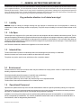
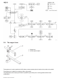
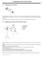
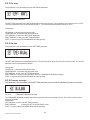
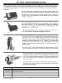
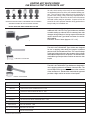
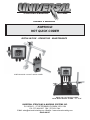
STENCILING & MARKING
SYSTEMS
OWNER’S MANUAL
KORTHO-D
HOT QUICK CODER
INSTALLATION - OPERATION - MAINTENANCE
KORTHO HQCD-100 HOT QUICK CODER
HQCD-100 HOT QUICK CODER
WITH BENCH MOUNT STAND - 12” X 18”
UNIVERSAL STENCILING & MARKING SYSTEMS, INC.
P.O. BOX 871 - ST. PETERSBURG, FLORIDA 33731 USA
PH: (727) 894-3027 FAX: (727) 821-7944
E-Mail: [email protected] Website: www.universal-marking.com
HQCD-08127
1
KORTHO Hot Quick Coder Manual
TABLE OF CONTENTS
Preface
Specifications
HQCD-100
1.
General Instructions Before Use
Liability
Life Span
Intended Use
Environment
Operational Personnel
2.
General Introduction
The Hot Quick Coder
The Control Box
The Control Panel
The Support Arm
3.
Safe Use
General Safety Measures
Explanation of attached Stickers
4.
Installation Of The Hot Quick Coder
Assembly instructions
Connection instructions
Requirements
5.
Preparing the Hot Quick Coder
Applying the Text Material
Adjusting the Position of the Hot Quick Coder
Preparation for use
6.
Operation of the Hot Quick Coder
Powering up
Printer Mode
Parameter / Message Screens
7.
The Hot Quick Coder During Use
Changing the Text Head
Replacing the Ink Roll
8.
Deactivating The Hot Quick Coder
Stopping printing for a short time
Stopping printing for a longer time
9.
Maintenance And Cleaning
Maintenance
Cleaning
10.
Print Quality Problems
Text Head does not move
Text Head moves but no print or only partial print visible
Printing too thick
The Text Head is not heating up
11.
Technical Data
Technical Data Hot Quick Coder
Technical Data Control Box for the Hot Quick Coder
12.
Connection Diagrams
Control Box Electrical Connection Diagram
Signal Device: Checking Wiring Connection
Setting the Hot Quick Coder to the correct mains voltage (110/220V)
13.
Troubleshooting
○
○
○
○
○
○
○
○
○
○
○
○
○
○
○
○
○
○
○
○
○
○
○
○
○
○
○
○
○
○
○
○
○
○
○
○
○
○
○
○
○
○
○
○
○
○
○
○
○
○
○
○
○
○
○
○
○
○
○
○
○
○
○
○
○
○
○
○
○
○
○
○
○
○
○
○
○
○
○
○
○
○
○
○
○
○
○
○
○
○
○
○
○
○
○
○
○
○
○
○
○
○
○
○
○
○
○
○
○
○
○
○
○
○
○
○
○
○
○
○
○
○
○
○
○
○
○
○
○
○
○
○
○
○
○
○
○
○
○
○
○
○
○
○
○
○
○
○
○
○
○
○
○
○
○
○
○
○
○
○
○
○
○
○
○
○
○
○
○
○
○
○
○
○
○
○
○
○
○
○
○
○
○
○
○
○
○
○
○
○
○
○
○
○
○
○
○
○
○
○
○
○
○
○
○
○
○
○
○
○
○
○
○
○
○
○
○
○
○
○
○
○
○
○
○
○
○
○
○
○
○
○
○
○
○
○
○
○
○
○
○
○
○
○
○
○
○
○
○
○
○
○
○
○
○
○
○
○
○
○
○
○
○
○
○
○
○
○
○
○
○
○
○
○
○
○
○
○
○
○
○
○
○
○
○
○
○
○
○
○
○
○
○
○
○
○
○
○
○
○
○
○
○
○
○
○
○
○
○
○
○
○
○
○
○
○
○
○
○
○
○
○
○
○
○
○
○
○
○
○
○
○
○
○
○
○
○
○
○
○
○
○
○
○
○
○
○
○
○
○
○
○
○
○
○
○
○
○
○
○
○
○
○
○
○
○
○
○
○
○
○
○
○
○
○
○
○
○
○
○
○
○
○
○
○
○
○
○
○
○
○
○
○
○
○
○
○
○
○
○
○
○
○
○
○
○
○
○
○
○
○
○
○
○
○
○
○
○
○
○
○
○
○
○
○
○
○
○
○
○
○
○
○
○
○
○
○
○
○
○
○
○
○
○
○
○
○
○
○
○
○
○
○
○
○
○
○
○
○
○
○
○
○
○
○
○
○
○
○
○
○
○
○
○
○
○
○
○
○
○
○
○
○
○
○
○
○
○
○
○
○
○
○
○
○
○
○
○
○
○
○
○
Parts Lists, & Diagrams
○
○
○
○
○
○
○
○
○
○
○
○
○
○
○
○
○
○
○
○
○
○
○
○
○
○
○
○
○
○
○
○
○
○
○
○
○
○ ○
○
○
○
○
○
○
○
○
○
○
○
○
○
○
○
○
○
○
○
○
○
○
○
○
○
○
○
○
○
○
○
○
○
○
○
○○
○
○
○
○
○
○
○
○
○
○
○
○
○
○
○
○
○
○
○
○
○
○
○
○
○
○
○○
○○
○○
○○
○○
○○
○○
○○
○○
○
○
○
○
○
○
○
○
○
○
○
○
○
○
○
○
○
○
○
○
○
○
○
○
○
○
○
○
○
○
○
○
○
○
○
○
○
○
○
○
○
○
○
○
○
○
○
○
○
○
○
○
○
○
○
○
○
○
○
○
○
○
○
○
○
○
○
○
○
○
○
○
○
○
○
○
○
○
○
○
○
○
○
○
○
○
○
○
○
○
○
○
○
○
○
○
○
○
○
○
○
○
○
○
○
○
○
○
○
○
○
○
○
○
○
○
○
○
○
○
○
○
○
○
○
○
○
○
○
○
○
○
○
○
○
○
○
○
○
○
○
○
○
○
○
○
○
○
○
○
○
○
○
○
○
○
○
○
○
○
○
○
○
○
○
○
○
○
○
○
○
○
○
○
○
○
○
○
○
○
○
○
○
○
○
○
○
○
○
○
○
○
○
○
○
○
○
○
○
○
○
○
○
○
○
○
○
○
○
○
○
○
○
○
○
○
○
○
○
○
○
○
○
○
○
○
○
○
○
○
○
○
○
○
○
○
○
○
○
○
○
○
○
○
○
○
○
○
○
○
○
○
○
○
○
○
○
○
○
○
○
○
○
○
○
○
○
○
○
○
○
○
○
○
○
○
○
○
○
○
○
○
○
○
○
○
○
○
○
○
○
○
○
○
○
○
○
○
○
○
○
○
○
○
○
○
○
○
○
○
○○
○
○
○
○
○
○○
○
○
○
○
○
○
○○
○
○
○
○
○
○
○
○
○
○
○
○
○
○
○○
○
○
○
○
○
○
○
○
○
○
○
○
○
○
○
○
○
○
○
○
○
○
○
○
○
○○
○
○
○
○
○
○
○
○
○○
○
○
○
○
○
○
○
○
○
○
○
○
○
○
○
○
○
○
○
○
○
○
○
○
○○
○
○
○
○
○
○
○
○
○○
○
○
○
○
○
○
○
○
○○
○
○
○
○
○
○
○
○
○
○○
○
○
○
○
○
○ ○
○
○
○
○
○
2
○
○
○
○
○
○
○
○
○
○
○
○
○
○
○
○
○
○ ○
○
○
○
○
○
○ ○
○
○
○
○
○
○
○
○
○
○ ○
○
○
○
○
○
○
○
○
○
○
○
○
○
○
○
○
○
○
○
○
○
○
○
○
○
○
○
○
○
○
○
○
○
○
○
○
○
○
○
○
○
○
○
○
○
○
○
○
○
○
○
○
○
○
○
○
○
○
○
○
○
○
○
○
○ ○
○
○
○
○
○
○
○
○
○
○
○
○
○
○
○
○
○
○
○
○
○ ○
○
○
○
○
○
○
○
○
○
○ ○
○
○
○
○
○
○
○
○
○
○ ○
○
○
○
○
○
○
○
○
○
○
○
○
○
○
○
○
○
○
○
○
○
○
○
○
○
○
○
○
○
○
○
○
○
○
○
○
○
○
○
○
○
○
○
○
○
○
○
○
○
○
○
○
○
○
○
○
○
○
○
○
○
○
○
○
○
○
○
○
○
○
○
○
○
○
○
○
○
○
○
○
○
○
○
○
○
○
○
○
○
○
○
○
○
○
○
○
○
○
○
○
○
○
○
○
○
○
○
○
○
○
○
○
○
○
○
○
○
○
○
○
○
○
○
○
○
○
○
○
○
○
○
○
○
○
○
○
○
○
○
○
○
○
○
○
○
○
○
○
○
○
○
○
KORTHO Hot Quick Coder Manual
○
○
○
○
14.
○
○
○
○
○
○
○
○
○
○
○
○
○
○
○
○
○
○
○
○
○
○
○
○
○
○
○
○
○
○
○
○
○
○
○
○
○
○
○
○
○
○
○
○
○
○
○
○
○
○
○
○
○
○
○
○
○
○
○
○
○
○
○
○
○
○
○
○
○
○
○
○
○
○
○
○
○
○
○
○
○
○
○
○
○
○
○
○
○
○
○
○
○
○
○
○
○
○
○
○
○
○
○
○
○
○
○
○
○
○
○
○
○
○
○
○
○
○
○
○
○
○
○
○
○
○
○
○
○
○
○
○
○
○
○
○
○
○
○
○
○
○
○
○
○
○
○
○
○
○
○
○
○
○
○
○
○
○
○
○
○
○
○
○
○
○
○
○
○
○
○
○
○
○
○
○
○
○
○
○
○
○
○
○
○
○
○
○
○
○
○
○
○
○
○
○
○
○
○
○
○
○
○
○
○
○
○
○
○
○
○
○
○
○
○
○
○
○
○
○
○
○
○
○
○
○
○
○
○
○
○
○
○
○
○
○
○
○
○
○
○
○
○
○
○
○
○
○
○
○
○
○
○
○
○
○
○
○
○
○
○
○
○
○
○
○
○
○
○
○
○
○
○
○
○
○
○
○
○
○
○
○
○
○
○
○
○
○
○
○
○
○
○
○
○
○
○
○
○
○
○
○
○
○
○
○
○
○
○
○
○
○
○
○
○
○
○
○
○
○
○
○
○
○
○
○
○
○
○
○
○
○
○
○
○
○
○
○
○
○
○
○
○
○
○
○
○
○
○
○
○
○
○
○
○
○
○
○
○
○
○
○
○
○
○
○
○
○
○
○
○
○
○
○
○
○
○
○
○
○
○
○
○
○
○
○
○
○
○
○
○
○
○
○
○
○
○
○
○
○
○
○
○
○
○
○
○
○
○
○
○
○
○
○
○
○
○
○
○
○
○
○
○
○
○
○
○
○
○
○
○
○
○
○
○
○
○
○
○
○
○
○
○
○
○
○
○
○
○
○
○
○
○
○
○
○
○
○
○
○
○
○
○
○
○
○
4
5
5
5
5
5
6
6
7
8
9
10
11
11
12
13
13
14
15
16
17
21
21
22
22
23
23
24
24
25
25
26
26
○
○
○
3
○
○
○
○
27
28
28
29
31
PREFACE
The Kortho Hot Quick Coder can be used on almost any material and surface. Whether you make 10,000 or
100,000 prints a day, the Kortho Hot Quick Coder offers the perfect solution for a variety of coding applications.
The unit accommodates up to three lines of text in a maximum printing area of 12 x 24 mm. The unique springloaded jumping head, with its “butterfly touch”, allows you to make perfect prints on moving products.
The Kortho Hot Quick Coder utilizes hot ink technology to provide clean, sharp, nearly instant dry impressions at
a high rate of speed. Ink rolls, which are dry to the touch at room temperature, are preheated prior to use in the
self-contained heating system. When hot, the ink in the roll becomes fluid and is then ready for operation. During
production, a spare roll can be stored in the unit’s preheat chamber to keep it ready for immediate use. Ink rolls
are available in black, white, red, yellow, green & blue and are supplied in convenient six-pack boxes.
CODER SPECIFICATIONS
The specification section includes a drawing of the Hot Quick Coder with the basic dimensions, the net weight,
print area, max printing & product speed, electrical specifications & working pressure.
KORTHO Hot Quick Coder Manual
3
SPECIFICATIONS
KORTHO HQCD-100 HOT QUICK CODER
11.558”
(294 mm)
8.951”
(227 mm)
7.562”
4.21”
(192 mm)
(107 mm)
Hot Quickcoder
7.404”
(188 mm)
6
4
2
8
0
BAR
5.429”
10
STOP
(138 mm)
START
(MOUNTING
HOLES)
TEST
0.175” DIA. (4.45 mm)
4 MOUNTING HOLES
11.83”
(300 mm)
13.87”
3.64”
(352 mm)
(92 mm)
.95”
3.58”
(24 mm)
.99”
(25 mm)
.50”
(6.4 mm)
7.28”
(91 mm)
Print Area:
Printing Speed Max:
Product Speed Max:
Working Pressure:
KORTHO Hot Quick Coder Manual
(6.4 mm)
0.472” X 0.945” - (12 x 24 mm)
300 Prints/min.
196 Ft./min. - (60m/min.)
56 PSI - (4 bar)
Electrical:
Electrical:
Coder Weight:
Control Weight:
4
110-130 VAC/1 A.
220-240 VAC/0.5 A.
3.75 Lbs. - (1.7 Kg,)
4.41 Lbs. - (2 Kg.)
1 - GENERAL INSTRUCTIONS BEFORE USE
The KORTHO, Hot Quick Coder was manufactured to exacting standards and every available step has been taken to assure
your complete satisfaction. It is most important, however, that the instructions contained in this manual are read and carefully
followed for best results. Failure to do so may result in unsatisfactory performance, damage to the equipment and personal
injury. Read through this user’s manual carefully before putting the Hot Quick Coder into use for the first time. Follow the order
indicated precisely when carrying out any of the actions described in this manual.
Pay particular attention to all stated warnings!
1.1
Liability
KORTHO accepts no liability for damage resulting from the improper or uninformed use of the equipment or caused by
maintenance or other work being carried out improperly. They also accept no liability for the normal wear-and-tear of the
product.
1.2
Life Span
The life span of the equipment is five years with normal use and compliance with the indicated maintenance periods. The life
span can be negatively influenced by improper/uninformed use of the equipment or improper maintenance, repair or modification.
No claims for guarantee or compensation for damages will be accepted in such instances. The Hot Quick Coder does not
contain any harmful substances or materials and can be scrapped or recycled at the end of its life span. The Ink Rolls should
be treated as small chemical waste.
N.B. The above statement is based on the legislation in force as at mid 1995.
1.3
Intended Use
The Hot Quickcoder-D printers are industrial printers and are designed to print directly on substrates.
Normal use means use under normal conditions as described in this manual.
The printer may not be used in areas, which have a fire or explosion hazard.
1.4
Environment
The environment in which the Hot Quick Coder may be installed must comply with a number of requirements relating to
humidity, temperature and vibrations.
The relative humidity should be between 10 and 90% (non-condensing).
The ambient temperature should be between 41 and 113°F.
The Hot Quick Coder may not be used in any areas having a fire or explosion hazard.
The Hot Quick Coder should be installed in a low vibration location.
1.5
Operational Personnel
Operators are qualified when they have read and understand this manual. A specific preliminary training is not required.
Technicians that carry out repairs and technical maintenance on the printer equipment should have secondary technical
education or comparable technical level of knowledge through practical experience.
Installation or servicing of the printer must only performed by qualified personnel of Korthofah BV or a local distributor,
which is designated by Korthofah BV. For customer installations authorisation must be obtained from Korthofah BV or a
local distributor, which is designated by Korthofah BV.
KORTHO Hot Quick Coder Manual
5
2 - GENERAL INTRODUCTION
The Hot Quick Coder (henceforth HQC) has been developed to apply small texts of one to three lines (max. line length 25 mm)
on a production line. The applications vary from loose products to a continuous product (e.g. packaging film).
The text can be applied to a stationary or a moving product. The maximum permitted product speed is 195 Feet/min. approx.
250 impressions per minute can be produced.
! WARNING:
After using the HQC, it cannot simply be deactivated. For the correct procedure read section 8 “Deactivating the Hot Quick
Coder”
2.1
The Hot Quick Coder
The code to be printed is applied to an exchangeable text
head via text characters or blocks. The text head is inked
with a Ink Roll which only delivers the inked (wax-based) at
high temperature. The Ink Roll is kept at temperature in the
heating ring of the HQC.
1 Preheating
2 Ink Roll
3 Text head
2.2
The Control box
A good print quality is achieved with a correct combination of stamping time, stamping pressure, temperature of the text head
and the setting of any counter-pressure plate.
1
2
3
4
17
5
16
4
6
6
2
8
0
BAR
10
15
7
14
8
13
11
9
10
12
KORTHO Hot Quick Coder Manual
6
1.
2.
3.
4.
5.
6.
7.
8.
9.
10.
11.
12.
13.
14.
15.
16.
17.
Control box
Control panel
Stop Key
LCD display
Cursor keypad (up, down, left, right)
Start key
Test key
strain relief
strain relief
Printer connection
Supply connection
power cord
Power switch
Printer fitting
air gauge
Supply pressure fitting
air regulator
2.2.1 Print Cycle
The purpose of the printer is to print an image on a substrate.
The print cycle is initiated with a trigger signal. This trigger must be generated by a host machine or a photocell, which
detects the product or special mark on the substrate.
2.2.2 User Interface
The user interface consists of two parts, the control panel and the menu structure of operator menus.
2.3
The Control Panel
The Control box contains a Control Panel with which specific functions can be performed such as switching the HQC on and
off and setting the print parameters. The Control Panel can also be used to issue a test print signal.
4
6
Hot Quickcoder
8
2
0
10
BAR
STOP
START
TEST
The cursor keys positioned below the LCD display on the control panel are used to navigate through the control box’s
screen menus.
Three command keys, STOP, START and TEST are provided.
The STOP key sets the printer in the stop-mode. In stop-mode the printing is stopped and “STOP” is displayed on the
LCD-display.
The START key sets the printer in run-mode and “RUN” is displayed on the LCD-display. The printer now accepts trigger
pulses from the host machine, if the alarm is not set.
The TEST key is only enabled in stop-mode. Press this key to make one test print. A test print will only be made if the
alarm signal is not set.
2.3.1 Indicator Icons
The Indicator icons on the LCD display, are provided to show the status:
Œ
‹
‰
T-icon: Indicates that the trigger input is set. And in RUN mode the print cycle will start.
P-icon: Indicates that the printer is printing.
H-icon:Indicates that the heating elements are switched on. This icon is flashing until the set temperature is reached.
KORTHO Hot Quick Coder Manual
7
2.4
The support arm
1 Support arm
2 Counter-pressure plate
The support arm is used to position the HQC and any counter-pressure plate in relation to the product to be printed.
The support arm is suitable for moving the HQC to any position.
The exceptionally short stamping time makes it possible to print directly onto a moving product without further
modifications.
KORTHO Hot Quick Coder Manual
8
3 - SAFETY USE
3.1
General Safety Measures
This product is designed to conform to all current directives, and their relevant harmonized standards, of the European
Council. It is important that the precautions indicated in this manual are strickly followed.
CE Machinery Directive (98/37/EC)
EN 292-1:1991 Safety of machinery - Basic concepts, general principles for design - Part 1 :Basic terminology, methodology.
EN 292-2:1991EN 292-2/A1:1995 Safety of machinery - Basic concepts, general principles for design - Part 2 :Technical
principles and specifications (with Amendment 1).
EMC Directive (89/336/EEC)
EN 55022 :1998EN 55022/A1:2000EN 55022/A2:2003Information Technology Equipment - Radio disturbance characteristics. Limits and methods of measurement (with Amendment 1).
EN 55024 :1998
EN 55024/A1:2001
EN 55024/A2:2003 Information Technology Equipment - Immunity characteristics. Limits and methods of measurement
(with Amendment 1).
EN 61000-3-2:2000 Electromagnetic compatibility.
(EMC) - Part 3-2: Limits - Limits for harmonic current emissions (equipment input current up to and including 16 A per
phase)(with Amendments 1 and 2).
EN 61000-3-3:1995EN 61000-3-3/A1:2001 Electromagnetic compatibility.
(EMC) - Part 3-3: Limitation of voltage changes, voltage fluctuations and flicker in public low-voltage supply systems for
equipment with rated current 16 A per phase and not subject to conditional connection
Low Voltage Directive (72/23/EEC)
EN 60950-1:2000 Safety of information technology equipment
3.1.1
Power supply
~ 220 / 240 V
~ 110 / 130 V
50 / 60 Hz
For safe operation, the power cable to the control box must be connected to a properly grounded single-phase supply of
the appropriate voltage. The power supply must comply with the power supply information that is written on the serialnumber label (located on the back of the control box.
Verify that no significant potential difference exists between the single-phase ground supply of the printer and the frame
ground of the host machine.
Note:
All external equipment that is connected to the control box interface must be double insulated to qualify the whole
installation as a separated extra-low voltage (SELV, Class II) system.
The wire colour code for the supply cable is:
BROWN for Line (L)
BLUE for Neutral(N)
GREEN/YELLOW for Protective Earth (PE)
When installing or servicing the equipment ensure that the host machine is stopped.
KORTHO Hot Quick Coder Manual
9
3.1.2 Precautions before power-up
Check at every printer power-up if all these connections are secured:
1. The mains power plug. (X1).
2. The printer cable. (X2).
3. The cable/conduit (X3/X4) between the control box and the coding unit.
3.1.3 Precautions when opening the control box
WARNING:
·
·
·
·
·
ALWAYS disconnect the power to the printer before removing any connectors or covers.
Switch the printer off.
Remove the plug from the mains power supply.
DO NOT operate the printer when any cover is removed.
DO NOT LEAVE tools, screws or other parts inside the control box when re-assembling the equipment.
3.1.4 Anti-static precautions
The printed circuit boards are static sensitive devices, which can be damaged if they are touched without the necessary
electrostatic discharge (ESD) precautions being taken. The ESD precautions involve the use of a grounded wrist strap and/
or conductive work mat.
During installation, servicing and handling of the printed circuit boards , the printed circuit boards must be protected from
electrostatic discharges.
3.2
Explanation of attached stickers
Various warning symbols are attached to the Hot Quick Coder.
Here is an explanation of the symbols on the stickers.
General danger
Danger due to
high temperature
Coding unit remains hot
for awhile after use
Maximum adjustable
pressure
KORTHO Hot Quick Coder Manual
10
Danger due to
high voltage parts
Voltage requirements
~ 220 / 240 V
~ 110 / 130 V
50 - 60 Hz
4 - INSTALLATION OF THE HOT QUICK CODER
4.1
Assembly instructions
Options for coding lengths of film
Options for coding products
During assembly ensure that sufficient space is left around the coder to replace the Ink Roll and to change the text head. If
necessary, set up the coder so that it revolves. The dimensional sketches are included in Appendix D.
1.
2.
3.
4.
5.
6.
7.
Mark the desired position of the holes for assembling the support (2.75” C-C). When determining the position, take
account of the fact that the text head (in the marked position) should ultimately be located approx. 5/64” - 1/8” from the
product surface to be printed (figure 7b).
Drill the mounting holes for the support (diameter 17/64”).
Assemble the support with 1/4” bolts (x2).
Fix the coder to the support.
Mark the desired position of the holes for assembling the Control box.
Drill the mounting holes for the Control box (3/16” diameter).
Assemble the Control box with #8 Screws and nuts (x4).
4.2
Connection instructions
! WARNINGS:
Before opening the control of the Hot Quick Coder, it should first be disconnected from the power. This is done by removing
the main power cable from the Control box.
Only a GROUNDED cable may be used for connecting the equipment
1.
2.
3.
4.
5.
6.
7.
Disconnect the printer from the voltage by removing the main power cable from the Control Box.
Open the Control box.
Check that the desired power supply is set correctly. (see appendix C).
Connect a sensor to supply the print command. The connection points and settings of the switch and jumpers are
given in appendix C.
Connect the power and control cable to the coding part.
Connect the Control box to the compressed air supply (setting approx. 58 psi) via the reducing valve.
Connect the HQC to a grounded connection.
KORTHO Hot Quick Coder Manual
11
4.3
Requirements
Provided by the customer:
·
·
·
Power: 115 or 230VAC, 50-60Hz (see fig. 4.1 for total power consumption).
A trigger-signal output of the host machine (print).
Sufficient space for installation and operation.
Optional:
·
A stop-signal input of the host machine (printer alarm).
Name
Type
VA (max)
Control box
HQC-D
10
Coding unit
HQC-D
100
Power consumption / type
The total power consumption is the sum of the control box and coding unit consumption.
Note:
Refer to Appendix B, ‘Connections’, ‘Electrical diagram I/O’ for the connection options.
4.3.1 Fuse values
SW 1
F1
F2
F3
F4
230 VAC
1 AT
1.6 AT
300m AT
500m AT
115 VAC
2 AT
3.15 AT
500m AT
500m AT
KORTHO Hot Quick Coder Manual
12
5 - PREPARING THE HOT QUICK CODER
5.1
Applying the text material
The text head has a printing area of 17 x 20 mm or 17 x 25 mm. The printing area has a specially shaped profile. The text
characters have the same profile on the reverse. The text characters are applied to the text head with a simple printing
movement.
The ‘blank space’ in the text characters on the same “line” should be completely filled with space characters.
5.2
Adjusting the position of the Hot Quick Coder
1
2
3
4
5
Crossing clamp
Adjusting ring
Hinge joint
Text head
Product
The HQC should be positioned such that the text head (5) is located in the position shown 2 to 3 mm from the surface to be
coded.
Activate the “HEAD-OUT” button (8) on the Control Panel (see section 5.1). This will fix the text head holder in the outermost
position.
Position the text head in the holder (see section 6.1).
Position the Hot Quick Coder so that the text head is located 2 to 3 mm from the surface to be coded.
Lock the crossing clamp (1).
Place the adjusting ring (2) against the underside of the crossing clamp.
Adjust the hinge joint (3) so that the product will be coded evenly. If necessary, reset the height.
Activate the “HEAD-IN” button (7) on the Control Panel (see section 5.1). The text head moves in.
A fine adjustment is available as an option. This can be used to adjust the distance to the product simply and accurately.
KORTHO Hot Quick Coder Manual
13
! WARNINGS:
Failure to observe the requisite heating up time of ±15 mins. leads to irrevocable damage to the text material and the
Ink Roll!
Failure to remove the handle from the text head can damage the HQC.
5.3
Preparation for use
1
2
3
4
1.
2.
3.
4.
5.
6.
7.
8.
9.
10.
11.
13.
Preheating chamber
Coding part
Text head holder
Handle
Take the text head and prepare it for use by applying the desired text material (see section 5.2).
Connect the system to the Control box by pressing the ON button.
Activate the HEAD-OUT button on the Control Panel (see section 5.1). This fixes the text head in the outermost
position.
Place the text head in the text head holder.
Remove the handle (4) by twisting it out of the text head.
Place a Ink Roll in the coding part (2) of the HQC; the cartridge must be pushed in until it clicks.
Activate the HEAD-OUT button on the Control box (see section 5.1).
Set the temperature adjustment on the Control box (section 5) to position 8 which sets the temperature to approx.
275°F.
Take account of 15 to 20 minutes’ heating up time.
Activate the START button on the Control box (see section 5.1).
Activate the supply of products.
Adjust the print quality further in accordance with the instructions in section 6.2.
Place a Ink Roll in the preheating chamber (1). This heats up a new Ink Roll during production so as to avoid
undesirable loss of production.
KORTHO Hot Quick Coder Manual
14
6 - OPERATION OF THE HOT QUICK CODER
This part describes the functions and procedures for operating the printer.
6.1
Powering up
1.
2.
3.
Check by visual inspection for damage of the printer.
Check if all of the relevant cables are connected.
Switch the control box on. The program boots while the printer type is displayed.
HOT QUICKCODER
Fig. 5.1 Firmware for Printer type message
4. After 3 seconds the Stop mode menu appears.
STOP 25…C
Fig. 5.2 STOP MODE menu
5. Proceed with step 10, if the parameters does not have to change.
Press the RIGHT ARROW to browse through the parameters and alter the desired parameter. Refer to section 5.3.
Parameter / message screens’ and Appendix C, ‘Quick reference’.
The parameter browse sequence is:
PRESET, SET DELAY, SET TEMP, SET TIME,
FIRMWARE message, SET LCD CONTRAST, SET ALARM, EXT.BUSY.
6. Press the STOP key to return to the STOP MODE menu.
7. Press the TEST key to make a test print.
8. Check the print quality and change the SET TIME and/or SET TEMP parameter if necessary (step 5).
Note:
The print pressure is also important for the print quality.
9. Press the START key to enter the RUN MODE menu.
RUN ###…C
Fig. 5.3 RUN MODE menu
Press the RIGHT ARROW to browse through the parameters and alter the desired parameter while in run mode.
Refer to section 5.3, ’Parameter / message screens’ and Appendix C, ‘Quick reference’.
The parameter browse sequence is:
SET DELAY, SET TEMP, SET TIME,
FIRMWARE message, SET LCD CONTRAST, SET ALARM, EXT.BUSY.
10. Press the STOP key to stop printing and enter the STOP MODE menu.
KORTHO Hot Quick Coder Manual
15
6.2
Printer mode
6.2.1 Stop mode
This menu is accessible from any screen (except error) by pressing the STOP key.
‹Œ STOP ‰ 25…C
STOP MODE MENU, with all possible indicator icons
In this mode the trigger signal will be ignored, but a TEST key press will make a test print. The current temperature is
represented by ### °C
Press button:
RIGHT ARROW: to shift to the PRESET LIST.
TEST: to make a test print.
START: to enter the RUN MODE MENU, the printer is now standby.
In this mode the following indicator icons can be displayed:
Œ
‹
‰
T-icon: Indicates that the trigger input is set (in this mode the trigger signal will be ignored).
P-icon: Indicates that the printer is printing (in this mode only by pressing the TEST key).
H-icon: Indicates that the heating elements are switched on. This icon is flashing until the set temperature is reached.
6.2.2 Run mode
This menu is only accessible from the STOP MODE menu by pressing the START key.
‹Œ RUN ‰ ###…C
RUN MODE MENU, with all possible indicator icons
In this mode the TEST key will be ignored. The current temperature is represented by ### °C.
Press button:
RIGHT ARROW: to shift to the SET DELAY parameter.
STOP: to return to the STOP MODE MENU and stop printing.
In this mode the following indicator icons can be displayed:
Œ
‹
‰
T-icon: Indicates that the trigger input is set (in this mode only by a trigger pulse).
P-icon: Indicates that the printer is printing (in this mode the TEST key will be ignored).
H-icon: Indicates that the heating elements are switched on. This icon is flashing until the set temperature is reached.
KORTHO Hot Quick Coder Manual
16
6.3
Parameter / message screens
6.3.1 Preset list
This list is only accessible from the STOP MODE menu.
PRESET #
PRESET LIST, the active preset is displayed
The printer can store 8 different presets. A preset is a collection of predefined parameter values. The parameter values of
the active preset can be altered by changing the desired parameter. The current preset list is represented by #.
Press button:
UP ARROW: to increase the PRESET LIST number.
DOWN ARROW: to decrease the PRESET LIST number.
LEFT ARROW: to shift to the STOP MODE MENU.
RIGHT ARROW: to shift to the SET DELAY parameter.
STOP: to return to the STOP MODE MENU.
6.3.2 Set delay
This parameter is only accessible from the RUN MODE menu or the PRESET list
SET DELAY: #.##s
SET DELAY parameter
The SET DELAY parameter delays the print after a trigger signal is received. The delay has a range from 0.00 to 2.00
seconds. The current parameter value is represented by #.##s.
Press button:
UP ARROW: to increase the parameter value.
DOWN ARROW: to decrease the parameter value.
LEFT ARROW: to shift to the PRESET LIST (stop mode) or the RUN MODE MENU (run mode).
RIGHT ARROW: to shift to the SET TEMP parameter.
STOP: to return to the STOP MODE MENU and stop printing.
KORTHO Hot Quick Coder Manual
17
6.3.3 Set temp
This parameter is only accessible from the SET DELAY parameter
SET TEMP: ###…C
Fig. 5.8 SET TEMP parameter
The SET TEMP parameter is the desired temperature of the print element. The temperature has a range from 0 to 165°C.
The current parameter value is represented by ### °C. The recommended temperature setting is 135°C.
Press button:
UP ARROW: to increase the parameter value.
DOWN ARROW: to decrease the parameter value.
LEFT ARROW: to shift to the SET DELAY parameter.
RIGHT ARROW: to shift to the SET TIME parameter.
STOP: to return to the STOP MODE MENU and stop printing.
6.3.4 Set time
This parameter is only accessible from the SET TEMP parameter
SET TIME: ##.#ms
Fig. 5.9 SET TIME parameter
The SET TIME parameter is the desired print time. The print time has a range from 5.0 to 50.0 milli-seconds. The current
parameter value is represented by ##.#ms.
Press button:
UP ARROW: to increase the parameter value.
DOWN ARROW: to decrease the parameter value.
LEFT ARROW: to shift to the SET TEMP parameter.
RIGHT ARROW: longer than two seconds to shift to the FIRMWARE VERSION message.
STOP: to return to the STOP MODE MENU and stop printing.
6.3.5 Firmware message
This parameter is only accessible from the SET TIME parameter (press the RIGHT ARROW longer than two seconds).
HQC V#.#.###
Fig. 5.10
FIRMWARE VERSION message
The FIRMWARE VERSION message shows the printer type and current firmware version. The current version is represented by V#.#.###.
Press button:
LEFT ARROW to shift to the SET TIME parameter.
RIGHT ARROW
to shift to the SET LCD CONTRAST menu.
STOP to return to the STOP MODE MENU and stop printing.
KORTHO Hot Quick Coder Manual
18
6.3.6 Set LCD contrast
This parameter is only accessible from the FIRMWARE message.
SET LCD CONTRAST
Fig. 5.11
SET LCD CONTRAST menu
In the SET LCD CONTRAST menu the LCD contrast can be changed.
Press button:
UP ARROW: to darken the LCD contrast, keep pressed until the desired contrast is set.
DOWN ARROW: to lighten the LCD contrast, keep pressed until the desired contrast is set
LEFT ARROW: to shift to the FIRMWARE VERSION message.
RIGHT ARROW: to shift to the SET ALARM parameter.
STOP: to return to the STOP MODE MENU and stop printing.
6.3.7 Set alarm
This parameter is only accessible from the SET LCD CONTRAST menu.
SET ALARM: *****
SET ALARM parameter
The SET ALARM parameter is the desired temperature alarm setting. The temperature alarm has four possible settings;:
OFF, ±5°C, ±10°C or ±15°C. The current parameter value is represented by *****.
The temperature range (±5°C, ±10°C or ±15°C) is related to the SET TEMP parameter. If the actual temperature is outside
the current temperature range the alarm is set, the printer stops printing and an error message is displayed.
Press button:
UP ARROW: to browse upwards through the settings.
DOWN ARROW: to browse downwards through the settings.
LEFT ARROW: to shift to the SET LCD CONTRAST menu.
RIGHT ARROW: to shift to the EXT.BUSY parameter.
STOP: to return to the STOP MODE MENU and stop printing.
6.3.8 Ext.busy
This parameter is only accessible from the SET ALARM parameter.
EXT.BUSY: #.##s
EXT.BUSY parameter
The busy signal is not present in the Hot Quickcoder hardware.
The EXT.BUSY parameter extends the busy signal. The extended busy time has a range from 0.00 to 2.50 seconds. The
current parameter value is represented by #.##s.
Press button:
UP ARROW: to increase the parameter value.
DOWN ARROW: to decrease the parameter value.
LEFT ARROW: to shift to the SET ALARM parameter.
STOP: to return to the STOP MODE MENU and stop printing.
19
KORTHO Hot Quick Coder Manual
6.3.9 User settings
Fill in this table with the values found by setting the printer parameters.
Use the table, as a reference, to set the printer parameters when the memory is reset to the default values.
Keep the table nearby, when calling the helpdesk of your local distributor.
FIRMWARE
V
•
PRESET
•
1
2
3
4
0.00 - 2.50s
x
x
x
x
PARAMETER
RANGE
5
6
7
8
SET DELAY
0.00 - 2.00s
SET TEMP
0 - 165°C
SET TIME
5.0 - 50.0ms
SET ALARM
OFF, + 5°C, + 10°C, + 15°C
EXT. BUSY
0.00 - 2.50s
x
x
x
x
PARAMETER
RANGE
SET DELAY
0.00 - 2.00s
SET TEMP
0 - 165°C
SET TIME
5.0 - 50.0ms
SET ALARM
OFF, + 5°C, + 10°C, + 15°C
EXT. BUSY
Printer parameters
Fill in this table and keep nearby, when calling the helpdesk of your local distributor.
Manufacturer host machine, type
Control box, serial number
Coding unit, serial number
Production plant
Production line
Type of substrate (product)
Production / print rate
Cycles / min
Ambient temperature (min, max)
°C (min) /
Printer environment information
KORTHO Hot Quick Coder Manual
20
°C (max)
7 - THE HOT QUICK CODER DURING USE
7.1
Changing the text head
Texts can be changed particularly quickly by changing the text head.
!
WARNINGS:
If the text head is removed during normal operation, it’s temperature is approximately 120°C!
Failure to remove the handle from the text head can damage the HQC.
1.
2.
3.
4.
5.
6.
7.
8.
9
10.
11.
Stop the supply of products.
Remove the product under (or in front of) the HQC or turn the HQC in its entirety away from the belt.
Activate the HEAD-OUT button on the Control Panel.
Twist the handle into the text head.
Use the handle to extract the text head from the text head holder.
Use the handle to position the (new) text head in the text head holder (check for blockages).
Twist the handle out of the text head.
Activate the HEAD-IN button on the Control Panel. This moves the text head back into neutral position.
Allow the new text head to reach operating temperature (approx. 2 minutes).
Replace the product under (or in front of) the HQC or turn the HQC in its entirety back towards the belt.
Start the supply of products.
7.2
Replacing the Ink Roll
If the print becomes less legible, the Ink Roll should be replaced. Replace the used roll with a roll which has already been
brought up to the correct temperature in the preheating chamber of the HQC.
!
WARNINGS:
Failure to follow the rules below when replacing an Ink Roll leads to damage to the text material, the Ink Roll and the
HQC itself!
The temperature of the text head is approximately 248°F!
1.
2.
3.
4.
5.
6.
7.
8.
9.
10.
11.
Activate the STOP button on the Control Panel.
Stop the supply of products;
Activate the HEAD-OUT button on the Control Panel;
Extract the used Ink Roll from the coding part of the HQC;
Remove the new Ink Roll from the preheating chamber;
Slide the new Ink Roll into the coding part of the HQC; the cartridge must be pushed in until it clicks;
Replace the removed product under (or in front of) the HQC;
Activate the HEAD-IN button on the Control Panel;
Activate the START button on the Control Panel.
Restart the supply of products;
Place a new Ink Roll in the preheating chamber.
KORTHO Hot Quick Coder Manual
21
8 - DEACTIVATING THE HOT QUICK CODER
8.1
Stopping printing for a short time
If the HQC is deactivated for a short time (during a break), the STOP button on the Control Panel should be pressed. The
thermostat part of the Control box continues to operate normally. When production is resumed, the START button on the
Control Panel must be pressed and the HQC is ready for immediate use.
8.2
Stopping printing for a longer time
If the HQC is deactivated for a longer time (several days):
1.
2.
3.
4.
5.
6.
7.
Stop the supply of products;
Activate the HEAD-OUT button on the Control Panel;
Remove the Ink Roll from the coding part of the HQC;
Activate the HEAD-IN button on the Control Panel. This moves the text head back into neutral position;
Now switch off the HQC using the OFF button on the Control Panel;
If necessary, remove the air pressure from the system;
If desired, resume the supply of products;
When the system is started up again, you should take account of the requisite heating up time of 15 to 20 minutes
!
WARNING:
Failure to observe the requisite heating up time of +15 minutes leads to irrevocable damage to the text
material and the Ink Roll!
KORTHO Hot Quick Coder Manual
22
9 - MAINTENANCE AND CLEANING
! WARNINGS:
Whenever the HQC is cleaned it should first be completely disconnected from the main power by removing the main plug
from the Control box (see figure 5)
Under no circumstances must the HQC be cleaned with water.
9.1
Maintenance
It is recommended to have the HQC system checked and/or reconditioned periodically. The recommended frequency is once
every two years depending on the degree of use of the HQC. No special tools are needed for carrying out maintenance work.
9.2
Cleaning
The HQC can best be cleaned using a dry brush. The control box can best be cleaned using a cleaner that will not damage
the plastic.
KORTHO Hot Quick Coder Manual
23
10 - PRINT QUALITY PROBLEMS
10.1
Text head does not move
POSSIBLE CAUSE
1.
Still in preheating mode.
(STOP status).
ACTION
Activate the START button on the Control Panel (normal
operation, see also 5.1.1).
2.
No air pressure.
Check reducing valve on the Control box.
3.
No supply voltage.
Measure the voltage on the 115V AC terminals in the command
box voltage.
4.
Fuse blown.
Check the fuses (on the PCB) in the Control box and replace if
blown (coil and/or system power not illuminated).
5.
Magnetic valve defective.
Replace the magnetic valve.
6.
Wire broken in the supply
and/or control cable.
Disconnect the system from the power and the cables. Test the
power cable and control cable. (heating & sensor). If necessary,
replace the power and control cable.
(see electrical connection diagram appendix C).
10.2
Text head moves but no printing or partial printing visible
POSSIBLE CAUSE
1.
Temperature too low.
2.
Stamping time too short.
ACTION
Set temperature to a higher value
Set stamping time to a higher value
Adjust the counter-pressure plate or HQC.
3.
Counter-pressure plate / product
far from the text head of the HQC.
4.
Check that the text material is not worn or that the (loose)
characters are varying in height. If necessary replace the block
or the characters
Fault in the text material.
Adjust the HQC in relation to the product to be coded.
Check the Ink Roll and replace if necessary.
5.
The HQC is out of alignment
with the product to be printed.
6.
The Ink Roll is empty (exhausted).
7.
The Ink Roll does not turn.
KORTHO Hot Quick Coder Manual
Check the position of the transport spring and adjust it if
necessary.
24
10.3
Printing too thick
ACTION
POSSIBLE CAUSE
1.
Temperature too high.
Set temperature to a lower value.
2.
Stamping time too long.
Set stamping time to a lower value.
3.
Text head too close to product.
Adjust distance if necessary to 2-3 mm.
10.4
The text head is not heating up
POSSIBLE CAUSE
ACTION
1.
Fuse blown.
Replace the fuse (accessible from outside).
2.
Wire broken in the supply.
Check the control cable and the main power cable for short
circuit or breakage. If necessary replace the power and control
cable (see electrical connection diagram appendix C).
3.
Sensor is broken or defective.
Test the sensor at points 1 and 2 of the connector on the HQC
(first disconnect the supply and control cable). The correct value
is 220 kOhm at 77°F. Replace the cable if the value deviates
more than 10%.
4.
Heating element defective.
Test the heating element at points 3 and 4 of the or short circuited
connector on the HQC (first disconnect the supply and control
cable). The correct value is 825 kOhm at 77°F. Replace the cable
if the value deviates more than 10%.
KORTHO Hot Quick Coder Manual
25
11 - TECHNICAL DATA
11.1
Technical data Hot Quick Coder
Mass of coding part [kg]
Mass of Control box [kg]
Length of supply and control cable [m].
Maximum printing area [mm x mm]
Maximum printing speed [prints/min]
Maximum product speed [m/min]
Operating pressure [bar]
Temperature range text head [°C]
Supply voltage (50/60Hz) [V AC]
Air consumption
Power consumption [Watt]
2
2.3
2.5
12 x 20 or 12 x 24
300
60
±4
80 - 160
110 / 220 V AC ±10% 50-60 Hz
0.3 ltr. at 4 bar.
110 max.
11.2 Setting the HQC to the correct main voltage (110/220V)
SW 1 is located on the PCB at the center of the box. This is used to select whether the Control box should operate on 115 V
AC or 230 VAC. This therefore depends on the available main voltage. This is set as standard to 115 VAC.
11.2.1 Trigger Signal from Parent Equipment
Connect the 24 VDC Signal in to: TRG/PNP (MINIMUM 15MS)
Connect the Common to: GND
Dip Switch settings: 1 = ON
2 = OFF
11.2.2 HQC-100-MST - MICRO-SWITCH TRIGGER
Set HQCD switch setting for NPN:
1 = ON
2 = OFF
BLACK
WHITE
KORTHO Hot Quick Coder Manual
26
TRG/NPN
GND
11.2.3 HQC-100-FPT - FOOT PEDAL TRIGGER
Set HQCD switch setting for NPN:
1 = ON
2 = OFF
BLACK
TRG/NPN
WHITE
GND
11.2.4 HQC-100-PCT-D - DIGITAL PHOTOCELL TRIGGER
Set HQCD switch setting for NPN:
1 = ON
2 = OFF
BROWN
+24V
BLACK
TRG/NPN
BLUE
GND
PINK
GND
11.2.5 HQC-100-PCT-LR - LONG RANGE PHOTOCELL TRIGGER
Set HQCD switch setting for NPN:
1 = ON
2 = OFF
BROWN
WHITE
BLUE
GRAY
BLACK
KORTHO Hot Quick Coder Manual
27
+24V
TRG/NPN
GND
NOT USED
NOT USED
12 - Connection Diagrams
12.1
Control Box Electrical Connection Diagram
KORTHO Hot Quick Coder Manual
28
TROUBLESHOOTING
1.1
Error 001
ERROR 001 ###…C
A too high or too low print temperature is detected.
The print temperature must be in between -10 to 200°C.
The actual temperature is displayed, here represented as ###°C
1.1
Error 002
Occurs only in the stop or run mode.
1.1.1 -20°C
ERROR 002 -20…C
The temperature sensor circuit is short circuited or the PT1000 sensor is defect.
1.1.1 300°C
ERROR 002 300…C
The temperature sensor circuit is open circuited or the PT1000 sensor is not connected or defect.
1.1
Error 003
Occurs only at system boot.
1.1.1 -20°C
ERROR 003 -20…C
The temperature sensor circuit is short circuited or the PT1000 sensor is defect.
KORTHO Hot Quick Coder Manual
29
TROUBLESHOOTING
1.1.1 300°C
ERROR 003 300…C
The temperature sensor circuit is open circuited or the PT1000 sensor is not connected or defect.
1.1
Error 004
Occurs only if the SET ALARM parameter is set.
ERROR 004 ###…C
The temperature alarm is activated.
A too high or too low print temperature deviation from the SET TEMP parameter value (±5°C, ±10°C or ±15°C) has
occurred.
The actual print temperature is displayed, here represented as ###°C.
1.1
Error 016
ERROR 016 ###…C
The print temperature algorithm does not detect a temperature change while the heating elements are switched on.
Perhaps the heating element(s) or PT1000 sensor are not connected or defect, the fuses F1/F2 are blown or the heating
circuit is defect.
The actual detected print temperature is displayed, here represented as ###°C.
1.1
LCD screen is not lit
Check the fuses F1, F2, F3 and F4. See Installation chapter.
KORTHO Hot Quick Coder Manual
30
HOT QUICK CODER TRIGGERING DEVICES
The print cycle of the HQC-100 Hot Quick Coder can be initiated or “triggered” in a number of ways, including
a foot pedal switch, production line mounted microswitch or a variety of photocells. Universal offers the following standard triggering systems in kit form which includes all the required hardware and complete installation
instructions.
The Foot Pedal Trigger is designed for manual initiation of the marking cycle.
This triggering device is commonly used when the coder is bench mounted
and products are manually placed under the marking head for imprinting.
The HQC-100-FPT Kit includes a Foot Pedal Switch, an 8 Foot Cable and
installation instructions.
The HQC-100-MST Micro-Switch is a contact trigger used to initiate the
print cycle of the HQC. This unit is permanently mounted to the production
line and has a 2.5” long trip lever with a low (2.5 Oz.) operating force. Body
Dimensions: 2.1” x 1.55” x 0.84”.
The HQC-100-MST Kit includes a Microswitch, Dust Proof Enclosure, 6
Foot Cable, Mounting Screws and installation instructions.
The HQC-100-PCT-D is a compact NPN, intelligent reflective beam photocell which is used for non-contact triggering of the HQC marking cycle.
This photocell features both automatic and manual calibration options, digital
readout, and a sensing range of up to 11.81” (300mm). This sensor excels
in applications where product shape, color variations and even clear packaging materials can cause other photocells to fail. Body Dimensions: 1.4”
x 0.785” x 0.48”.
The HQC-100-PCT-D Kit includes the Photocell, Mounting Bracket, 6 Foot
Cable and installation instructions. IP-67 Rated for harsh, wet environments.
The HQC-100-PCT-LR is a compact, long range retro-reflective Photocell which is which is used for non-contact triggering of the HQC marking
cycle. This unit has an effective range up to 10 feet and is rated for harsh
environments and suitable for installation in wet areas. Body Dimensions:
2.6” x 1.21” x 0.48”.
The HQC-100-PCT-LR Kit includes the Photocell, mounting bracket, 6
foot cable and 3” diameter reflector. (Not recommended for sensing clear
plastic or glass containers.)
PART NUMBER
DESCRIPTION
HQC-100-FPT
FOOT PEDAL TRIGGER KIT
HQC-100-MST
MICRO-SWITCH TRIGGER KIT
HQC-100-PCT-D
PHOTOCELL TRIGGER KIT
HQC-100-PCT-LR
PHOTOCELL TRIGGER KIT - LONG RANGE
KORTHO Hot Quick Coder Manual
31
KORTHO HOT QUICK CODER
INK ROLLS & TEXT PLATE PARTS LIST
Ink rolls, which are dry to the touch at room temperature,
are preheated prior to use in the self-contained heating system. The Hot Quick Coder utilizes hot ink technology to
provide clean, sharp, nearly instant dry impressions at a
high rate of speed. When hot, the ink in the roll becomes
fluid and is then ready for operation. A spare roll can be
stored in the unit’s preheat chamber during production to
keep it ready for immediate use.
INK ROLLS ARE SUPPLIED IN CONVENIENT SIX-PACK BOXES
AND ARE AVAILABLE IN THE FOLLOWING COLORS:
BLACK, BLUE, RED, WHITE, GREEN AND YELLOW.
Additional HQC-100-FTH Flat Type Holders are available
to enable setting up codes off line for extremely fast code
changes during production. Having a spare eliminates the
need to let the active Type Holder cool down for comfortable handling.
Print Area: 12mm x 24mm (Approx: 0.5” x 1.0”)
FLAT TYPE HOLDER - 4 RIB
The HQC-100-THCONCAVE Type Holders are designed
for use in applying codes along the length of cylindrical
parts such as round bottles and cans. The concave shape
of this type holder conforms to the curvature of the cylinder
and enables multiple lines to be printed. The ribbed rubber
mat hold the type and provides a cushion to ensure a clear
imprint
CONCAVE TYPE HOLDER
The HQC-100-THCONVEX Type Holders are designed for
use in applying codes to the bottoms of aerosol cans. The
convex shape of the type holder conforms to the curvature
of the can bottom. A ribbed rubber mat holds the type and
provides a slight cushion to ensure a clear imprint.
CONVEX TYPE HOLDER
PART NUMBER
DESCRIPTION
HQC-6-BK
S-11 BLACK HOT QUICK CODER INK ROLLS - 6/PK
HQC-6-BL
S-12 BLUE HOT QUICK CODER INK ROLLS - 6/PK
HQC-6-RD
S-14 RED HOT QUICK CODER INK ROLLS - 6/PK
HQC-6-WH
S-15 WHITE HOT QUICK CODER INK ROLLS - 6/PK
HQC-6-GR
S-17 GREEN HOT QUICK CODER INK ROLLS - 6/PK
HQC-6-YL
S-16 YELLOW HOT QUICK CODER INK ROLLS - 6/PK
HQC-100-FTH
FLAT TYPE HOLDER - 4 RIB
HQC-100-THCONCAVE CONCAVE TYPE HOLDER
HQC-100-THCONVEX
CONVEX TYPE HOLDER
KORTHO Hot Quick Coder Manual
32
KORTHO HIGH-TEMP RIBtype ® SILICONE TYPE
®
The KORTHO Hot Quick Coder utilizes High-Temp RIBtype Silicone type. This interchangeable ribbed type is
available in a variety of sizes as shown below. The High-Temp rubber type is for the KORTHO Hot Quick Coder
only. All boxed sets contain an assortment of characters, including punctuation, in varying quantities. The chart
below shows the quantity of each character in our listed boxed sets.
A + ASSORTMENT
CHARACTER
A
B
C
D
E
F
G
H
I
J
K
L
M
N
O
P
Q
R
S
T
U
V
W
X
Y
Z
QUANTITY IN SET
7
5
5
5
7
5
5
5
5
5
5
5
5
7
5
5
3
5
5
5
5
5
5
3
3
5
CHARACTERS
Å
Ä
Ö
Ü
Æ
Ø
1
2
3
4
5
6
7
8
9
0
.
,
-
/
QUANTITY IN SET
2
2
2
2
2
2
2
2
2
2
2
2
2
2
2
2
1
3
1
1
C + ASSORTMENT
FIGURES
1
2
3
4
5
6
7
8
9
0
.
,
-
/
QUANTITY IN SET
9
9
9
9
9
9
9
9
9
9
2
3
2
2
STYLE NO.
*TYPE FACE HEIGHT
2/8
2 mm = 5/64”
2/10
2.5 mm = 3/32”
2/12
3 mm = 1/8”
2/14
3.5 mm = 9/64”
2/16
4 mm = 5/32”
2/20
5 mm = 3/16”
LETTER TYPE SAMPLE
FIGURE TYPE SAMPLE
* TYPE FACE HEIGHTS ARE APPROXIMATE
®
KORTHO HIGH-TEMP RIBtype SILICONE TYPE
STYLE NO.
STOCK NO.
A+ ASSORTMENT
STOCK NO.
C+ ASSORTMENT
2/8
UR-28A+
UR-28C+
2/10
UR-210A+
UR-210C+
2/12
UR-212A+
UR-212C+
2/14
UR-214A+
UR-214C+
2/16
UR-216A+
UR-216C+
2/20
UR-220A+
UR-220C+
KORTHO Hot Quick Coder Manual
33
HQCD-814532 - KORTHO DIGITAL HOT QUICK CODER
CONTROL BOX ASSEMBLY
16
23
22
21
16
24
20
19
18
17
16
15
1
14
2
13
12
2
3
4
KORTHO Hot Quick Coder Manual
5
6
7
8
10
9
34
11
HQCD-814532 - KORTHO DIGITAL HOT QUICK CODER
CONTROL BOX PARTS LIST
KEY NO.
PART NUMBER
QTY. REQD.
1
HQCD-814418
1
POWER PCB HQC-D
2
HQCD-152877
2
HOSE NIPPLE M5 X 4MM
3
HQCD-165098
2
COUPLING UNIT HOSE
4
HQC-160564
1
3/2 MAGNETIC VALVE 1/8 - 1, 5-24 VDC
5
HQCD-321758
1
COUPLING 1/8”
6
HQCD-165142
1
DIMINISHING COUPLING - 1/8 X 1/8 K
7
HQCD-161557
1
KNEE JOINT 6 X 1/8”
8
HQC-156517
1
PRESSURE GAUGE 0-10 BAR 1/8 “
9
HQC-152765
1
FILTER - REDUCTION UNIT 1/8”
10
HQCD-165139
1
KNEE JOINT 6 X M5
11
HQC-152819
1
REDUCING COUPLING 1/8XM5
12
HQC-814841
1
CORD BLACK HQC / HP
13
HQCD-814838
1
CORD BLUE HQC / HP
14
HQCD-165101
1
SWITCH CONTROL BOX HQC / HP
15
HQCD-814825
1
CHASSIS PART MAINS VOLTAGE
16
HQC-160481
12
17
HQCD-814771
1
CHASSIS PART CONTROL BOX
18
HQC-158632
2
COUPLING NUT PG 9
19
HQCD-321704
1
TOP CONTROL BOX HP / HQC / KWP
20
HQCD-321732
1
BOTTOM CONTROL BOX
21
HQCD-814867
1
EARTH WIRE PCB HQC / HP
22
HQC-811869
1
POWER CORD, 115 VAC
23
HQCD-814434
1
PCB FRONT PLATE BOX
24
HQCD-814879
1
CONTROL CABLE PCB HQC / HP
DESCRIPTION
ROUND HEAD COUNTER SUNK SCREW 3 X 8 ST.
Fuse Specifications for 115 VAC 60 Hz Systems
PART NUMBER
FUSE
HQCD-USMS-FI
F1
DESCRIPTION
2 A (5X20) S FUSE
3.15 A (5 X 20) S FUSE
F2
HQC-155972
F3
HQCD-USMS-F3-F4
500 mA (5 X 20) S FUSE
F4
HQCD-USMS-F3-F4
500 mA (5 X 20) S FUSE
KORTHO Hot Quick Coder Manual
35
HQCD-815007 - KORTHO DIGITAL HOT QUICK CODER
PRINT HEAD ASSEMBLY & PARTS LIST
1
3
2
DESCRIPTION
KEY NO.
PART NUMBER
1
HQC-154782
1
CLAMPING SCREW, M8 x 35MM
2
HQC-154755
1
WASHER, 8MM
3
HQC-159399
8
SCREW, M5 X 10MM - BUTTON HEAD
KORTHO Hot Quick Coder Manual
QTY. REQD.
36
HQC-803399 - KORTHO HOT QUICK CODER
FORK ASSEMBLY & PARTS LIST
2
3
5
4
1
6
KEY NO.
PART NUMBER
QTY. REQD.
1
HQC-803399
1
FORK ASSEMBLY, HQC
2
HQC-304764
1
FORK, PRINT HEAD
3
HQC-156454
1
WASHER, M4 X 3 SS
4
HQC-118087
1
BEARING
5
HQC-151699
1
SCREW, M4 X 12 SS
6
HQC-154318
1
SET SCREW, M4 X 10 SS
KORTHO Hot Quick Coder Manual
DESCRIPTION
37
HQC-809238 - KORTHO HOT QUICK CODER
AIR CYLINDER ASSEMBLY
1
2
3
10
9
6
5
4
11
8
7
12
13
16
14
17
17
15
18
19
22
21
KORTHO Hot Quick Coder Manual
20
38
23
HQC-809238 - KORTHO HOT QUICK CODER
AIR CYLINDER PARTS LIST
KEY NO.
PART NUMBER
QTY. REQD.
1
HQC-809238
1
AIR CYLINDER ASSEMBLY, HQC-AT - COMPLETE
2
HQC-809422
1
CYLINDER BOTTOM ASSEMBLY. - HQC
3
HQC-160659
1
STRAIGHT TUBE COUPLING, M5 X 6
4
HQC-156389
1
BUFFER RING, HQC
5
HQC-158127
1
RETURN SPRING, AIR CYLINDER
6
HQC-151451
1
HEX NUT, M8 X 1 SS
7
HQC-163071
1
WASHER
8
HQC-304859
1
BUSHING, DRIVING BLOCK
9
HQC-319365
1
BOTTOM, CYLINDER - HQC
10
HQC-156377
1
RETAINING RING, CYLINDER BOTTOM - HQC
11
HQC-151814
1
PISTON GASKET RING 16X9X2, 1MM
12
HQC-802518
1
PISTON, HQC
13
HQC-809419
1
DRIVING BLOCK, HQC
14
HQC-315919
1
DRIVING BLOCK, HQC
15
HQC-315808
1
SPRING HOLDER, HQC
16
HQC-159654
1
SET SCREW, SPRING HOLDER - M4 X 6
17
HQC-317587
1
SPRING, INK ROLL INDEX
18
HQC-151702
1
SCREW, M4 X 16 SS
19
HQC-118087
1
BEARING
20
HQC-151798
1
LOCK WASHER, M4 X 1 SS
21
HQC-151699
1
SCREW, M4 X 12 SS
22
HQC-151798
1
LOCK WASHER, M4 X 1 SS
23
HQC-810851
1
DRIVING BLOCK/SPRING HOLDER ASSEMBLY - COMPLETE
KORTHO Hot Quick Coder Manual
DESCRIPTION
39
HQC-809855 - KORTHO HOT QUICK CODER
TEXT PLATE HOLDER ASSEMBLY & PARTS LIST
2
4
3
5
1
KEY NO.
PART NUMBER
QTY. REQD.
1
HQC-809855
1
TEXT PLATE HOLDER ASSEMBLY, HQC - COMPLETE
2
HQC-802801
1
GUIDE BRACKET
3
HQC-809842
1
TEXT PLATE HOLDER, HQC
4
HQC-126572
2
COMPRESSION SPRING
5
HQC-304818
4
SCREW, PRINTING HEAD
6
HQC-304999
1
SPRING CLIP, PRINTING HEAD
KORTHO Hot Quick Coder Manual
DESCRIPTION
40
6
KORTHO HQC-100 HOT QUICK CODER
CAM HOLDER & PARTS LIST
1
2
KEY NO.
PART NUMBER
QTY. REQD.
1
HQC-316454
1
CAM HOLDER, HQC
2
HQC-802941
1
ECCENTRIC BRASS PLUG WITH BALLBEARING
KORTHO Hot Quick Coder Manual
DESCRIPTION
41
HQCD-814994 - KORTHO DIGITAL HOT QUICK CODER
HEATING ELEMENT ASSEMBLY
GROUND
HEATING ELEMENT
SENSOR
KORTHO Hot Quick Coder Manual
42
HQC-809477 - KORTHO HOT QUICK CODER
MOUNTING BRACKET ASSEMBLY & PARTS LIST
2
1
3
5
4
6
7
9
8
10
12
11
KEY NO.
PART NUMBER
QTY. REQD.
1
HQC-316034
1
CROSS CLAMP BLOCK - HQC
2
HQC-158897
1
HANDLE, M8 X 25 - HQC
3
HQC-153478
1
CLAMPING SCREW, M8 X 20
4
HQC-315992
1
MOUNTING ARM - HQC
5
HQC-153452
1
LOCK WASHER, M8 X 1
6
HQC-155174
1
SOCKET HEAD CAP SCREW, M8 X 25
7
HQC-316664
1
MOUNTING STUD - HQC
8
HQC-154429
1
SOCKET HEAD CAP SCREW, M6 X 25
9
HQC-316062
1
PLATEN - HQC
10
HQC-315989
1
MOUNTING COLUMN - HQC
11
HQC-316018
1
MOUNTING BASE - HQC
12
HQC-809464
1
SHAFT COLLAR & HARDWARE KIT
KORTHO Hot Quick Coder Manual
DESCRIPTION
43