1
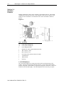
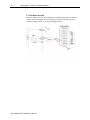
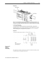
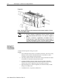
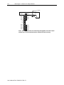
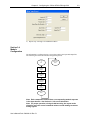
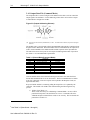
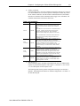
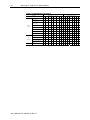
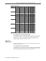
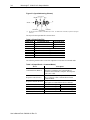
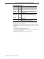
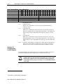
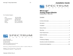
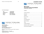
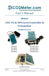
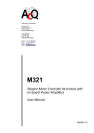
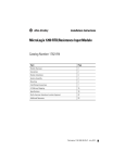
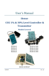
User’s Manual Pub. 0300246-01 Rev. B 1762 8 Channel Analog Output Module Catalog Number: 1762sc-OF8 ii MicroLogix™ 1200 8 Ch Output Module Important Notes 1. Please read all the information in this owner’s guide before installing the product. 2. The information in this owner's guide applies to hardware Series A and firmware version 1.00 or later. 3. This guide assumes that the reader has a full working knowledge of the relevant processor. Notice The products and services described in this owner's guide are useful in a wide variety of applications. Therefore, the user and others responsible for applying the products and services described herein are responsible for determining their acceptability for each application. While efforts have been made to provide accurate information within this owner's guide, Spectrum Controls assumes no responsibility for the accuracy, completeness, or usefulness of the information herein. Under no circumstances will Spectrum Controls be responsible or liable for any damages or losses, including indirect or consequential damages or losses, arising out of either the use of any information within this owner's guide or the use of any product or service referenced herein. No patent liability is assumed by Spectrum Controls with respect to the use of any of the information, products, circuits, programming, or services referenced herein. The information in this owner's guide is subject to change without notice. Limited Warranty Spectrum Controls warrants that its products are free from defects in material and workmanship under normal use and service, as described in Spectrum Controls literature covering this product, for a period of 1 year. The obligations of Spectrum Controls under this warranty are limited to replacing or repairing, at its option, at its factory or facility, any product which shall, in the applicable period after shipment, be returned to the Spectrum Controls facility, transportation charges prepaid, and which after examination is determined, to the satisfaction of Spectrum Controls, to be thus defective. This warranty shall not apply to any such equipment which shall have been repaired or altered except by Spectrum Controls or which shall have been subject to misuse, neglect, or accident. In no case shall the liability of Spectrum Controls exceed the purchase price. The aforementioned provisions do not extend the original warranty period of any product which has either been repaired or replaced by Spectrum Controls. User’s Manual Pub. 0300246-01 Rev. B iii Table of Contents IMPORTANT NOTES ............................................................................................................................................ II NOTICE .............................................................................................................................................................. II LIMITED WARRANTY .......................................................................................................................................... II CHAPTER 1 MODULE OVERVIEW ..................................................................................................................... 1‐1 SECTION 1.1 GENERAL DESCRIPTION .............................................................................................................................. 1‐1 SECTION 1.2 INPUT TYPES AND RANGES ......................................................................................................................... 1‐1 SECTION 1.3 DATA FORMATS ....................................................................................................................................... 1‐1 SECTION 1.4 HARDWARE FEATURES .............................................................................................................................. 1‐2 1.4.1 LED Indicator ............................................................................................................................................. 1‐2 SECTION 1.5 SYSTEM OVERVIEW ................................................................................................................................... 1‐3 1.5.1 Module Power‐up ..................................................................................................................................... 1‐3 1.5.2 Module Operation ..................................................................................................................................... 1‐4 CHAPTER 2 INSTALLATION AND WIRING .......................................................................................................... 2‐1 SECTION 2.1 COMPLIANCE TO EUROPEAN UNION DIRECTIVES ............................................................................................. 2‐1 2.1.1 EMC Directive ............................................................................................................................................ 2‐1 2.1.2 Low Voltage Directive ............................................................................................................................... 2‐1 SECTION 2.2 POWER REQUIREMENTS ............................................................................................................................ 2‐1 SECTION 2.3 GENERAL CONSIDERATIONS ........................................................................................................................ 2‐2 2.3.1 Hazardous Location Considerations .......................................................................................................... 2‐2 2.3.2 Prevent Electrostatic Discharge ................................................................................................................ 2‐3 2.3.3 Remove Power .......................................................................................................................................... 2‐3 2.3.4 Selecting a Location .................................................................................................................................. 2‐3 SECTION 2.4 MOUNTING ............................................................................................................................................. 2‐3 2.4.1 Minimum Spacing ..................................................................................................................................... 2‐4 2.4.2 DIN Rail Mounting .................................................................................................................................... 2‐4 2.4.3 Panel Mounting ........................................................................................................................................ 2‐5 SECTION 2.5 SYSTEM ASSEMBLY ................................................................................................................................... 2‐5 SECTION 2.6 FIELD WIRING CONNECTIONS ...................................................................................................................... 2‐6 2.6.1 Wiring Diagram ........................................................................................................................................ 2‐7 2.6.2 Wiring the Finger‐Safe Terminal Block ..................................................................................................... 2‐9 2.6.3 Terminal Door Label .................................................................................................................................. 2‐9 SECTION 2.7 MODULE INDICATORS .............................................................................................................................. 2‐10 CHAPTER 3 CONFIGURING THE 1762SC‐OF8 USING RSLOGIX 500 ..................................................................... 3‐1 SECTION 3.1 THINGS YOU SHOULD KNOW ...................................................................................................................... 3‐1 SECTION 3.2 MODULE MEMORY MAP ........................................................................................................................... 3‐1 SECTION 3.3 ADD MODULE TO LOGIX 500 ...................................................................................................................... 3‐2 SECTION 3.4 MODULE CONFIGURATION......................................................................................................................... 3‐3 3.4.1 Output Data File (Command Mode) ......................................................................................................... 3‐4 3.4.2 Output Data File (Normal Run Mode) ....................................................................................................... 3‐7 SECTION 3.5 MODULE STATUS ...................................................................................................................................... 3‐7 3.5.1 Input Data File (Command Mode) ............................................................................................................ 3‐7 3.5.2 Input Data File (Normal Run Mode) .......................................................................................................... 3‐9 SECTION 3.6 CONFIGURATION LADDER SAMPLE ............................................................................................................. 3‐10 APPENDIX A MODULE SPECIFICATIONS ............................................................................................................ A‐1 User’s Manual Pub. 0300246-01 Rev. B iv MicroLogix™ 1200 8 Ch Output Module PREFACE Read this preface to familiarize yourself with the rest of the manual. This preface covers the following topics: Who should use this manual How to use this manual Related publications Conventions used in this manual Rockwell Automation support Who Should Use This Manual Use this manual if you are responsible for designing, installing, programming, or troubleshooting control systems that use Allen-Bradley I/O and/or compatible controllers, such as MicroLogix 1100 or 1200. How to Use This Manual As much as possible, we organized this manual to explain, in a task-by-task manner, how to install, configure, program, operate and troubleshoot a control system using the 1762sc-OF8. Related Documentation The table below provides a listing of publications that contain important information about Allen-Bradley PLC systems. Document Title MicroLogix™ 1200 User Manual MicroLogix™ 1200 Technical Data MicroLogix 1200 and MicroLogix 1500 Programmable Controllers Instruction Set Reference Manual Allen-Bradley Programmable Controller Grounding and Wiring Guidelines Document Number 1762-UM001 1762-TD001 1762-RM001 1770-4.1 If you would like a manual, you can: Download a free electronic version from the internet at www.theautomationbookstore.com Purchase a printed manual by: o Contacting your local distributor or Rockwell Automation representative o Visiting www.theautomationbookstore.com and placing your order o Calling 1.800.963.9548 (USA/Canada) or 001.330.725.1574 (Outside USA/Canada) User’s Manual Pub. 0300246-01 Rev. B v Conventions Used in This Manual The following conventions are used throughout this manual: Bulleted lists (like this one) provide information not procedural steps. Numbered lists provide sequential steps or hierarchical information. Italic type is used for emphasis Bold type identifies headings and sub-headings ! Attention Are used to identify critical information to the reader User’s Manual Pub. 0300246-01 Rev. B vi MicroLogix™ 1200 8 Ch Output Module User’s Manual Pub. 0300246-01 Rev. B Chapter 1 Module Overview This chapter describes the 1762sc-OF8 output module. The module provides 8 analog output channels that can be configured for current or voltage. Included is information about: General description Output types and ranges Data Formats Hardware Features System overview and module operation Section 1.1 General Description The output module supports current and voltage type outputs. The module converts the digital value stored in each channel’s output command word to an analog current or voltage signal. Each output channel is individually configured via software for a specific output type, data format, and provides open-circuit or short-circuit detection and indication. Section 1.2 Input Types and Ranges The tables below list the output types and their associated ranges. Voltage Selection -10V to +10V 0 to +5V 0 to +10V 1 to +5V Current Selection 0 to 20mA 4 to 20mA Range (V dc) - 11.0 to + 11.0 0.0 to 5.5 0.0 to +11.0 0.0 to +5.5 Range (mA) 0 to 20.4 3.92 to 20.4 Section 1.3 Data Formats For each module the data can be configured for: Engineering units Scaled-for-PID Raw/proportional data Percent of full range User’s Manual Pub. 0300246-01 Rev. B 1-2 MicroLogix™ 1200 IO 8 Ch Output Module Section 1.4 Hardware Features Module configuration is done via the controller’s programming software. The module configuration is stored in the memory of the controller. Refer to your controller’s user manual for more information. The illustration below shows the module’s hardware features. Figure 1-1 Item Description 1a Upper panel mounting tab 1b Lower panel mounting tab 2 Power diagnostic LED 3 Module door with terminal identification label 4 Bus connector (male) 5 Bus connector cover 6 Flat ribbon cable with bus connector (female) 7 Terminal block 8 DIN rail latch 9 Pull loop 1.4.1 LED Indicator The 1762 output module uses a single green LED to show operational status of the module. The LED will illuminate solid when the PLC is in run mode and the module properly configured. If the module is not properly configured, or if the PLC is not in run mode, the LED will blink rapidly. The following blink codes are the only exception: User’s Manual Pub. 0300246-01 Rev. B Chapter 1: Module Overview 1-3 Table 1-1 (LED Blink Codes) Blink Code Description 1 Rapid Blink PLC not in run mode, or no valid module configuration present Solid Module is in run mode (Normal Operation) 3 Factory calibration in progress 4 Factory calibration invalid 5 Module is in command mode Section 1.5 System Overview The module communicates to the controller through the bus interface. The module also receives 5 and 24V dc power through the bus interface. 1.5.1 Module Power-up At power-up, the module performs a check of its internal circuits, memory, and basic functions. During this time, the module status LED remains off. If no faults are found during power-up diagnostics, the module status LED blinks rapidly waiting for command mode. After power-up checks are complete, the module waits for command mode and then valid channel configuration data. If an invalid configuration is detected, the module generates a configuration error and remains in command mode. Once the module is properly configured and enabled, it continuously converts the output command value to a proportional analog output signal. Each time a channel command value is read by the output module, that data value is tested by the module for an over-range or under-range condition. If such a condition is detected, a unique bit is set in the channel status word. The channel status word is described in section 3.5.2 Input Data File. Using the module image table, the controller reads the two’s complement binary converted input data from the module. This typically occurs at the end of the program scan or when commanded by the control program. If the controller and the module determine that the data transfer has been made without error, the data is used in the control program. 1 All outputs are disabled until the PLC goes into run mode and the module receives a valid configuration. User’s Manual Pub. 0300246-01 Rev. B 1-4 MicroLogix™ 1200 IO 8 Ch Output Module 1.5.2 Module Operation When the module receives a new command value from the output image, the module’s circuitry converts the digital value to an analog current/voltage signal using a DAC (Digital to Analog Converter). See the block diagram below. User’s Manual Pub. 0300246-01 Rev. B Chapter 2 Installation and Wiring This chapter will cover: Compliance to European union directives Power requirements General considerations Mounting Field wiring connections Module Indicators Section 2.1 Compliance to European Union Directives This product is approved for installation within the European Union and EEA regions. It has been designed and tested to meet the following directives. 2.1.1 EMC Directive The 1762sc-OF8 module is tested to meet Council Directive 89/336/EEC Electromagnetic Compatibility (EMC) and the following standards, in whole or in part, documented in a technical construction file: IEC 61000-6-4 Electromagnetic compatibility (EMC) - Part 6-4: Generic standards - Emission standard for industrial environments IEC 61000-6-2 Electromagnetic compatibility (EMC) – Part 6-2: Generic standards – Immunity for industrial environments This product is intended for use in an industrial environment. 2.1.2 Low Voltage Directive This product is tested to meet Council Directive 73/23/EEC Low Voltage, by applying the safety requirements of EN 61131-2Programmable Controllers, Part 2 – Equipment Requirements and Tests. For specific information required by EN61131-2, see the appropriate sections in this publication, as well as the following Allen-Bradley publications: Industrial Automation, Wiring and Grounding Guidelines for Noise Immunity, publication 1770-4.1 Automation Systems Catalog, publication B113 Section 2.2 Power Requirements The module receives power through the bus interface from the +5V dc/+24V dc system power supply. The maximum current drawn by the module is shown in the table below. User’s Manual Pub. 0300246-01 Rev. B 2-2 MicroLogix™ 1200 IO 8 Ch Output Module 5 VDC 24 VDC 30 mA 250 mA @ 18.7V, 195mA @ 24V Use the table below to determine the maximum number of OF8 modules that can be installed in a MicroLogix system. Table 2-1 Controller ML1100 ML1200 (24pt.) ML1200 (40pt.) ML1400 (ALL) Max 5V Bus Current (mA) 800 400 600 1500 Max 24V Bus Current (mA) 700 350 500 1500 Max # of OF8 Modules 3 1 2 6 Section 2.3 General Considerations 1762 I/O is suitable for use in an industrial environment when installed in accordance with these instructions. Specifically, this equipment is intended for use in clean, dry environments Pollution degree 22 and to circuits not exceeding Over Voltage Category II3(IEC 60664-1)4. 2.3.1 Hazardous Location Considerations This equipment is suitable for use in Class I, Division 2, Groups A, B, C, D or nonhazardous locations only. The following WARNING statement applies to use in hazardous locations. ! Attention EXPLOSION HAZARD Substitution of components may impair suitability for Class I, Division 2. Do not replace components or disconnect equipment unless power has been switched off or the area is known to be nonhazardous. Do not connect or disconnect components unless power has been switched off or the area is known to be non-hazardous. This product must be installed in an enclosure. All wiring must comply with N.E.C. article 501-4(b). 2 Pollution Degree 2 is an environment where, normally, only non-conductive pollution occurs except that occasionally a temporary conductivity caused by condensation shall be expected. 3 Over Voltage Category II is the load level section of the electrical distribution system. At this level transient voltages are controlled and do not exceed the impulse voltage capability of the product’s insulation. 4 Pollution Degree 2 and Over Voltage Category II are International Electrotechnical Commission (IEC) designations. User’s Manual Pub. 0300246-01 Rev. B Chapter 2: Installation and Wiring 2-3 2.3.2 Prevent Electrostatic Discharge ! Attention Electrostatic discharge can damage integrated circuits or semiconductors if you touch analog I/O module bus connector pins or the terminal block on the input module. Follow these guidelines when you handle the module: Touch a grounded object to discharge static potential. Wear an approved wrist-strap grounding device. Do not touch the bus connector or connector pins. Do not touch circuit components inside the module. If available, use a static-safe work station. When it is not in use, keep the module in its static-shield bag. 2.3.3 Remove Power ! Attention Remove power before removing or inserting this module. When you remove or insert a module with power applied, an electrical arc may occur. An electrical arc can cause personal injury or property damage by: Sending an erroneous signal to your system’s field devices, causing unintended machine motion Causing an explosion in a hazardous environment Electrical arcing causes excessive wear to contacts on both the module and its mating connector and may lead to premature failure. 2.3.4 Selecting a Location Reducing Noise Most applications require installation in an industrial enclosure to reduce the effects of electrical interference. Analog inputs are highly susceptible to electrical noise. Electrical noise coupled to the analog inputs will reduce the performance (accuracy) of the module. Group your modules to minimize adverse effects from radiated electrical noise and heat. Consider the following conditions when selecting a location for the analog module. Position the module: Away from sources of electrical noise such as hard-contact switches, relays, and AC motor drives Away from modules which generate significant radiated heat. Refer to the module’s heat dissipation specification. In addition, route shielded, twisted-pair analog input wiring away from any high voltage I/O wiring. Section 2.4 Mounting ! Attention Do not remove protective debris strip until after the module and all other equipment near the module is mounted and wiring is complete. Once wiring is complete and the module is free of debris, carefully remove protective debris strip. Failure to remove strip before operating can cause overheating. User’s Manual Pub. 0300246-01 Rev. B 2-4 MicroLogix™ 1200 IO 8 Ch Output Module 2.4.1 Minimum Spacing Maintain spacing from enclosure walls, wireways, adjacent equipment, etc. Allow 50.8 mm (2 in.) of space on all sides for adequate ventilation, as shown: Figure 2-1 Note: 1762 expansion I/O may be mounted horizontally only. ! Attention During panel or DIN rail mounting of all devices, be sure that all debris (metal chips, wire strands, etc.) is kept from falling into the module. Debris that falls into the module could cause damage when power is applied to the module. 2.4.2 DIN Rail Mounting The module can be mounted using the following DIN rails: 35 x 7.5 mm (EN 50 022 - 35 x 7.5) or 35 x 15 mm (EN 50 022 - 35 x 15). Before mounting the module on a DIN rail, close the DIN rail latch. Press the DIN rail mounting area of the module against the DIN rail. The latch will momentarily open and lock into place. Use DIN rail end anchors (Allen-Bradley part number 1492-EA35 or 1492-EAH35) for environments with vibration or shock concerns. User’s Manual Pub. 0300246-01 Rev. B Chapter 2: Installation and Wiring 2-5 Figure 2-2 Note: For environments with extreme vibration and shock concerns, use the panel mounting method described below, instead of DIN rail mounting. 2.4.3 Panel Mounting Use the dimensional template shown below to mount the module. The preferred mounting method is to use two M4 or #8 Pan Head screws per module. M3.5 or #6 Pan Head screws may also be used, but a washer may be needed to ensure a good ground contact. Mounting screws are required on every module. Figure 2-3 Section 2.5 System Assembly The expansion I/O module is attached to the controller or another I/O module by means of a ribbon cable after mounting as shown below. User’s Manual Pub. 0300246-01 Rev. B 2-6 MicroLogix™ 1200 IO 8 Ch Output Module Figure 2-4 Note: Use the pull loop on the connector to disconnect modules. Do not pull on the ribbon cable. EXPLOSION HAZARD In Class I, Division 2 applications, the bus connector must be fully seated and the bus connector cover must be snapped in Attention place. In Class I, Division 2 applications, all modules must be mounted in direct contact with each other as shown on page 24. If DIN rail mounting is used, an end stop must be installed ahead of the controller and after the last 1762 I/O module. ! Section 2.6 Field Wiring Connections Consider the following when wiring your system: General Power and output wiring must be in accordance with Class 1, Division 2 wiring methods, Article 501-4(b) of the National Electric Code, NFPA 70, and in accordance with the authority having jurisdiction. The analog common (COM) is not connected to earth ground inside the module. All terminals are electrically isolated from the system. To ensure optimum accuracy for voltage type outputs, limit overall cable impedance by keeping all analog cables as short as possible. Locate the I/O system as close to your voltage type sensors or actuators as possible. Digital and analog power must be supplied by an Isolated Secondary Limited Energy Low Voltage source. Use Belden™ 8761, or equivalent, shielded wire. User’s Manual Pub. 0300246-01 Rev. B Chapter 2: Installation and Wiring 2-7 USE SUPPLY WIRES SUITALE FOR 20°C ABOVE SURROUNDING AMBIENT ! Attention ! Attention UTILISER DES FILS D’ALIMENTATION QUI CONVIENNENT A UNE TEMPERATURE DE 20°C AU-DESSUS DE LA TEMPERATURE AMBIANTE Grounding This product is intended to be mounted to a well-grounded mounting surface such as a metal panel. Additional grounding connections from the module’s mounting tabs or DIN rail (if used) are not required unless the mounting surface cannot be grounded. Under normal conditions, the drain wire (shield) should be connected to the metal mounting panel (earth ground). Keep shield connection to earth ground as short as possible. Ground the shield drain wire at one end only. The typical location is as at the module end. If it is necessary to connect the shield drain wire at the module end, connect it to earth ground using a panel or DIN rail mounting screw. Refer to Industrial Automation Wiring and Grounding Guidelines, AllenBradley publication 1770-4.1, for additional information. Noise Prevention Route field wiring away from any other wiring and as far as possible from sources of electrical noise, such as motors, transformers, contactors, and ac devices. As a general rule, allow at least 15.2 cm (6 in.) of separation for every 120V of power. Routing field wiring in a grounded conduit can reduce electrical noise. If field wiring must cross ac or power cables, ensure that they cross at right angles. If noise persists for a device, try grounding the opposite end of the cable shield or ground both ends of the shield. 2.6.1 Wiring Diagram Refer to the following wiring diagrams for field wiring connections. Figure 2-5 (Wiring Diagram) User’s Manual Pub. 0300246-01 Rev. B 2-8 MicroLogix™ 1200 IO 8 Ch Output Module Shield RTN 0 RTN 1 RTN 2 RTN 3 OUT 0 Load OUT 1 + - OUT 2 OUT 3 NC NC RTN 4 RTN 5 RTN 6 RTN 7 OUT 4 OUT 5 OUT 6 OUT 7 Note: All return terminals are electrically tied together, but each output should use its own associated return terminal for best accuracy. User’s Manual Pub. 0300246-01 Rev. B Chapter 2: Installation and Wiring 2-9 2.6.2 Wiring the Finger-Safe Terminal Block Figure 2-6 ! Attention Be careful when stripping wires. Wire fragments that fall into a module could cause damage when power is applied. Once wiring is complete, ensure the module is free of all metal fragments. When wiring the terminal block, keep the finger-safe cover in place. 1) Refer to section 2.6.1for proper field wiring connections. 2) Route the wire under the terminal pressure plate. You can use the stripped end of the wire or a spade lug. The terminals will accept a 6.35 mm (0.25 in.) spade lug. See Figure 2-6. 3) Tighten the terminal screw making sure the pressure plate secures the wire. Recommended torque when tightening terminal screws is 0.904 Nm (8 in-lbs). 4) After wiring is complete, remove the debris shield. 2.6.3 Terminal Door Label A removable, write-on label is provided with the module. Remove the label from the door, mark your unique identification of each terminal with permanent ink, and slide the label back into the door. Your markings (ID tag) will be visible when the module door is closed. See figure below. User’s Manual Pub. 0300246-01 Rev. B 2-10 MicroLogix™ 1200 IO 8 Ch Output Module Figure 2-7 (Door Label) Section 2.7 Module Indicators The 1762 output module uses a single green LED to show operational status of the module. The LED will illuminate solid when the PLC is in run mode and the module properly configured. If the module is not properly configured, or if the PLC is not in run mode, the LED will blink rapidly. The following blink codes are the only exception: Table 2-2 (LED Blink Codes) Blink Code Description 5 5 Rapid Blink PLC not in run mode, or no valid module configuration present Solid Module is in run mode (Normal Operation) 3 Factory calibration in progress 4 Factory calibration invalid 5 Module is in command mode All outputs are disabled until the PLC goes into run mode and the module receives a valid configuration. User’s Manual Pub. 0300246-01 Rev. B Chapter 3 Configuring the 1762sc-OF8 Using RSLogix 500 This chapter covers the following subjects: Things you should know Module memory map Add module to Logix 500 Module configuration Module status Configuration Ladder Sample Section 3.1 Things You Should Know This chapter describes how to configure the OF8 module for the MicroLogix 1100, 1200 and 1400 system using RSLogix 500 programming software. Section 3.2 Module Memory Map The module uses 8 input words and 8 output words for input data and configuration. The following figure describes the data mapping for the module. Figure 3-1 (Module Memory Map) Read Input Image I:0 to I:7( 8 words) (Input Data) Write Output Image O:0 to O:7 (8 words) (Configuration or Output Data) User’s Manual Pub. 0300246-01 Rev. B 1762sc-OF8 3-2 MicroLogix™ 1200 IO 8 Ch Output Module Section 3.3 Add Module to Logix 500 The following procedure describes how to add the OF8 module to the RSLogix 500 programming software. 1.) Create a new RSLogix 500 project and select either a Micro 1100, 1200, or 1400 processor. 2.) Double-click “I/O Configuration” from the project tree. 3.) Select the first empty slot and then double-click the “Other—Requires I/O Card Type ID” option, from the I/O configuration screen. 4.) Enter the module profile data as shown in the figure below and click “OK”. User’s Manual Pub. 0300246-01 Rev. B Chapter 3: Configuring the 1762sc-OF8 for RSLogix 500 3-3 5.) Repeat steps 1 through 4 for additional modules. Section 3.4 Module Configuration The OF8 module is configured using a process that employs the input and output files. The following flow chart describes the configuration process. Transition To Run Module Enters Run Mode Unlock Command Issued Write Configuration Data Issue Load Configuration Command Issue Exit Command 600 ms Delay Note: Each command issued will have a corresponding module response in the input data file. See Section 3.5.1 for more information. Note: For proper operation, during the 600 ms delay, the output words should be set to the correct command values to avoid sending erroneous analog signals. User’s Manual Pub. 0300246-01 Rev. B 3-4 MicroLogix™ 1200 IO 8 Ch Output Module 3.4.1 Output Data File (Command Mode) The output data file is used to configure each channel for the OF8 as well as control the output signal of each channel. Use the addressing scheme below to locate the 8 output words needed to configure the module. Figure 3-2 (Output Addressing Scheme) (1) I/O located on the controller (embedded I/O) is slot 0. I/O added to the controller (expansion I/O) begins with slot 1. The module enters a special mode called Command Mode when the PLC transitions from Program mode to Run mode. When the module enters Command Mode, the output file is used to send commands to the module and the module responds via the input data file. The table below shows the layout for each output word during both modes of operation. See Table 3-6 for command mode response data. Table 3-1 (Normal Mode/Command Mode) Output Word O:e.0 O:e.1 O:e.2 O:e.3 O:e.4 O:e.5 O:e.6 O:e.7 Output File Normal Run Mode Channel 0 Data Word Channel 1 Data Word Channel 2 Data Word Channel 3 Data Word Channel 4 Data Word Channel 5 Data Word Channel 6 Data Word Channel 7 Data Word Command Mode Command Data Word 1 (Ch0 & 1)6 Data Word 2 (Ch2 & 3)6 Data Word 3 (Ch4 & 5)6 Data Word 4 (Ch6 & 7)6 Fixed Word 1 (0xCDEF) Fixed Word 2 (0xFEDC) Fixed Word 3 (0x5A5A) Once the module detects the transition from Program to Run it waits until the Fixed Words and Command code are set to valid values. The first command must be Unlock. If an error is detected, a non-zero response will be placed in the Response Code (see Input Data File table). Keep in mind the module is constantly polling the output file as it is updated by the controller. The module will validate each command using the following three step process: 1) Validate Fixed Words 1-3: These words must always be valid during Command Mode. An error will be posted in the Response Code until these are correct. Commands will not be validated and processed until these words are set correctly. The fixed words are posted above in Table 3-1. 6 See Table 3-3 (Data Words 1 through 4) User’s Manual Pub. 0300246-01 Rev. B Chapter 3: Configuring the 1762sc-OF8 for RSLogix 500 3-5 2) Validate Command: If the Fixed Words are valid, the Command word will be checked. If it is not set to a valid command, an error will be reported. Initially the module only checks for the Unlock command. After the Unlock command is detected, the module must detect a transition in the Command word to trigger a new command. The available commands are listed in the table below. Table 3-2 (Commands) Command Value Unlock 0xFFF0 Clear Command 0xFF00 Load Config 0xFFF1 Exit 0xFF80 Description This MUST be the first command issued after entering Command Mode. If not, an error will be posted. Data Words are ignored when the module enters command mode.. The module does not need to detect a command transition to Unlock. It simply waits for the Fixed Words to be valid and Unlock command set. This command is ignored if issued multiple times (Response Code will be 0). Once Command Mode is unlocked it remains unlocked until it has been successfully configured and the Exit command issued. Clears the command buffer to allow a command to be reissued. Since the module only knows a command is issued when the Command word changes, the only way to re-issue a command is to cause a transition. This command gives the user a null command to do that. The response is always 0. No other action is taken with this command. Data Words 1-4 must contain valid channel configuration data for all channels. See Data Words table below. Configuration will be validated. An error will be posted for the first invalid channel configuration found. If the configuration is invalid, the configuration info in the Data Words may be modified but to re-issue the Load Config, the Clear Command must be issued first. Delay 600ms then enter run state with configuration. The delay begins after the response. If configuration is not valid, the module will remain in Command Mode until a valid configuration is entered. 3) Data Words 1-4: If the command requires valid data in the Data Words, they are validated and a response is placed in the Response Code register (i.e. Word I:e.1). See section 3.5.1 for a description of each response code. The following table lists the possible configuration settings for each of the 8 channels. Each Data Word contains two channel configurations. See Table 3-1 for Data Word layout. User’s Manual Pub. 0300246-01 Rev. B 3-6 MicroLogix™ 1200 IO 8 Ch Output Module Table 3-3 (Data Words 1 through 4) To Select Channels 1, 3, 5, or 7 15 Output Type 14 13 12 11 4 to 20 mA 9 0 8 0 0 to 20 mA 0 0 -10 to 10 V 0 1 0 to 10 V 0 1 to 5 V 0 to 5 V Reserved Channel Disabled Data Format Channels 0, 2,4 or 6 10 0 7 6 5 4 3 2 0 1 0 0 0 1 0 0 1 0 0 1 0 1 1 0 1 1 1 0 0 1 0 0 1 0 1 1 0 1 1 1 0 1 1 0 1 1 1 1 1 1 Scaled for PID 0 0 0 0 Engineering Units 0 1 0 1 Percent Range Raw/Proportional Data 1 0 1 0 1 1 1 1 Unused User’s Manual Pub. 0300246-01 Rev. B 0 0 0 0 0 0 Chapter 3: Configuring the 1762sc-OF8 for RSLogix 500 3-7 Table 3-4 (Data Format) Output Range 4..20mA 0..20mA +/-10V 0 to 5V 0 to 10V 1 to 5V Output Value 20.40 mA Condition High Limit Raw/Prop 32767 EU 20400 PID 16793 % FS 10250 20.00 mA High Range 31176 20000 16383 10000 4.00 mA Low Range -32450 4000 0 0 3.92 mA Low Limit -32768 3920 -82 -50 20.40 mA High Limit 32767 20400 16711 10200 20.00 mA High Range 31482 20000 16383 10000 0.00 mA Low Limit/Range -32768 0 0 0 11.00 V dc High Limit 32767 11000 17202 11000 10.00 V dc High Range 29788 10000 16383 10000 -10.00 V dc Low Range -29788 -10000 0 -10000 -11.00 V dc Low Limit -32768 -11000 -819 -11000 5.50 V dc High Limit 32767 5500 18021 11000 5.00 V dc High Range 26809 5000 16383 10000 0.00 V dc Low Range -32768 0 0 0 0.00 V dc Low Limit -32768 0 0 0 11.00 V dc High Limit 32767 11000 18021 11000 10.00 V dc High Range 26809 10000 16383 10000 0.00 V dc Low Range -32768 0 0 0 0.00 V dc Low Limit -32768 0 0 0 5.50 V dc High Limit 32767 5500 18431 11250 5.00 V dc High Range 26809 5000 16383 10000 1.00 V dc Low Range -20853 1000 0 0 0.00 V dc Low Limit -32768 000 -4096 -2500 3.4.2 Output Data File (Normal Run Mode) The output data file is used to configure each channel for the OF8 as well as control the output signal of each channel. Use the addressing scheme shown in Figure 3-2 above. In normal run mode, output words 0 through 7 control the analog output signal for channels 0 through 7 respectively. See Table 3-1 above. Section 3.5 Module Status Input data for the OF8 consists of status information, channel configuration information and module configuration status. 3.5.1 Input Data File (Command Mode) In command mode, the input data file returns module configuration status used during the configuration process. Refer to section 3.4.1 for more information regarding command mode. Use the addressing scheme below to locate the 8 input words. User’s Manual Pub. 0300246-01 Rev. B 3-8 MicroLogix™ 1200 IO 8 Ch Output Module Figure 3-3 (Input Addressing Scheme) (1) I/O located on the controller (embedded I/O) is slot 0. I/O added to the controller (expansion I/O) begins with slot 1. The layout for the input data file is shown below. Table 3-5 (Input Data File) Input Word Normal Run Mode Command Mode I:e.0 General Status Word 0 Command Echo I:e.1 Output Status Word 1 (ch 0-3) Response Code I:e.2 Output Status Word 2 (ch 4-7) Response Channel I:e.3 Echo Config (ch 0-1) I:e.4 Echo Config (ch 2-3) I:e.5 Echo Config (ch 4-5) I:e.6 Echo Config (ch 6-7) I:e.7 Not Used The following table describes each of the input data words when in command mode. Table 3-6 (Input Words - Command Mode) Word Description Matches Command Word 0 (i.e. O:e.0). When this word matches the Command Word, Command Echo (Word 0) it indicates the command is complete. The Response Code is now valid. Non-zero is an error (see Response Codes). Response Code (Word 1) This is valid only when Command Echo matches Command Word. If Response Code error, indicates which channel. Response Channel (Word 2) Only applies to commands that involve channels. Echo of Data (Word 1) Chan 1 Config Chan 0 Config Echo of Data (Word 2) Chan 3 Config Chan 2 Config Echo of Data (Word 3) Chan 5 Config Chan 4 Config Echo of Data (Word 4) Chan 7 Config Chan 6 Config Not Used (Word 7) User’s Manual Pub. 0300246-01 Rev. B Chapter 3: Configuring the 1762sc-OF8 for RSLogix 500 3-9 Table 3-7 (Response Codes) Name Value Description Success 0x0000 The command was completed successfully. Invalid Command 0xF001 An invalid command code was issued. A command was issued before the Unlock was Locked 0xF002 given. One or more Fixed Words invalid. The module will Invalid State 0xF003 remain in its previous state until all of the words are set correctly. A configuration for one of the channels is invalid. Invalid Config 0xF004 Check Response Channel to determine which one. First error detected is displayed. An attempt was made to exit Command Mode before a configuration was loaded. Either load the No Config 0xF005 default config or manually enter a configuration for all channels. Calibration is invalid. Module requires factory Invalid Cal 0xF006 calibration before it can be configured. Note: Response codes are not be considered valid until the Command Echo matches the issued command. Note: Response codes will remain valid after the Exit command until the timeout expires. After that, normal Input File operation takes over. Words 02 are status. 3.5.2 Input Data File (Normal Run Mode) In normal run mode, the input data file displays general module status, channel status and an echo of each channel configuration. Use the addressing scheme in Figure 3-3 to locate the 8 input words. User’s Manual Pub. 0300246-01 Rev. B 3-10 MicroLogix™ 1200 IO 8 Ch Output Module Table 3-8 (Input Words - Normal Run Mode) Word Bit 15 14 13 12 11 10 9 8 7 6 5 4 3 2 1 0 General Status (Word 0) I:e.0 - S7 S6 S5 S4 S3 S2 S1 S0 Output Status (Word 1) I:e.1 - LD3 U3 O3 - LD2 U2 O2 - LD1 U1 O1 - LD0 U0 O0 Output Status (Word 2) I:e.2 - LD7 U7 O7 - LD6 U6 O6 - LD5 U5 O5 - LD4 U4 O4 Echo Config (Word 3) <Ch 1 Config>7 <Ch 0 Config>7 7 Echo Config (Word 4) <Ch 2 Config>7 <Ch 3 Config> 7 Echo Config (Word 5) <Ch 5 Config> <Ch 4 Config>7 7 Echo Config (Word 6) <Ch 7 Config> <Ch 6 Config>7 Not Used (Word 7) 0x0000 - = Not used. Bit set to 0. S<x> = General status bit. If a bit is set (1) then there is an error associated with that channel (i.e. under/over range). U<x> = Under range flag. When set to 1, indicates the output word value set by the user is below the defined Low Range value (see Output Data Format table). The channel will output voltage or current (depending on the range type) to the Low Limit value. O<x> = Over range flag. When set to 1, indicates the output word value set by the user is above the defined High Range value (see Output Data Format table). The channel will output voltage or current (depending on the range type) up to the High Limit value. LD<x> = Load Error. If the channel is configured for voltage mode, this bit indicates a short circuit. If the channel is configured for current mode, open circuit is indicated. The error bit is cleared (0) at the time the condition is cleared. Section 3.6 Configuration Ladder Sample The following ladder sample demonstrates how to configure the module when the PLC transitions from Program to Run, using the process described in Section 3.4. ! Attention 7 Use the “Command” bit (B3:0/0) in the following ladder sample as a condition before any instruction that writes data to one of the 8 module output words. Failure to do so can result in the module rejecting the configuration and not going into run mode (i.e. a rapid blinking module status LED). See Table 3-3 (Data Words 1 through 4) User’s Manual Pub. 0300246-01 Rev. B Chapter 3: Configuring the 1762sc-OF8 for RSLogix 500 User’s Manual Pub. 0300246-01 Rev. B 3-11 3-12 MicroLogix™ 1200 IO 8 Ch Output Module User’s Manual Pub. 0300246-01 Rev. B Chapter 3: Configuring the 1762sc-OF8 for RSLogix 500 User’s Manual Pub. 0300246-01 Rev. B 3-13 3-14 MicroLogix™ 1200 IO 8 Ch Output Module User’s Manual Pub. 0300246-01 Rev. B Appendix A Module Specifications General Specifications Specification Value Dimensions 90 mm (height) x 87 mm (depth) x 40 mm (width) height including mounting tabs is 110 mm 3.54 in. (height) x 3.43 in. (depth) x 1.58 in. (width) height including mounting tabs is 4.33 in. Approximate Shipping Weight (with carton) 279g (0.615 lbs.) Storage Temperature -40°C to +85°C (-40°F to +185°F) Operating Temperature -20°C to +60°C (-4°F to +140°F) Operating Humidity Operating Altitude 5% to 95% non-condensing 2000 meters (6561 feet) Operating: 10 to 500 Hz, 5G, 0.030 in. max. peak-topeak Operating: 30G 30 mA at 5V dc Max 250 mA @ 18.7V, 195mA @ 24V 4.9W Total Max Distance rating of 6. Maximum number of modules by controller type: Max 5V Max 24V Bus Bus Max # of Controller Current Current Modules ML1100 800 700 3 ML1200 400 350 1 (24pt.) ML1200 600 500 2 (40pt.) ML1400 1500 1500 6 None Up to two wires of size #14-#22 AWG (solid) or #16#22 AWG (stranded) To ensure proper operation and high immunity to electrical noise, always use Belden 8761 (shielded, twisted pair) or equivalent wire for voltage and current sensors Vibration Shock Bus Current Draw (max.) Heat Dissipation Maximum number of modules on the bus Fusing Wire Size Wire Type Isolation Channel to Rack Channel to Channel Module Power LED Vendor I.D. Product Type User’s Manual Pub. 0300246-01 Rev. B 707 VDC for 1 minute (withstand voltage) Return lines are connected together. No isolation between channels. On: indicates power is applied and module not faulted. See Section 1.4.1 for more information. 58 10 A-2 MicroLogix™ 1200 IO 8 Ch Output Module Specification Product Code Agency Certification Hazardous Environment Class Radiated and Conducted Emissions Electrical /EMC: ESD Immunity (IEC61000-4-2) Radiated Immunity (IEC61000-4-3) Fast Transient Burst (IEC61000-4-4) Surge Immunity (IEC61000-4-5) Conducted Immunity (IEC61000-4-6) 8 Value 21 C-UL listed (under CSA C22.2 No. 142) UL 508 listed CE compliant for all applicable directives Class I, Division 2, Hazardous Location, Groups A, B, C, D (ISA 12.12.01, C-UL under CSA C22.2 No. 213) Operating Temperature Code T6 EN55011 The module has passed testing at the following levels: 4 kV contact, 8 kV air, 4 kV indirect 10 V/m, 80 to 1000 MHz, 80% amplitude modulation, +900 MHz keyed carrier 2 kV, 5 kHz 1 kV galvanic gun 10V, 0.15 to 80 MHz8 Conducted Immunity frequency range may be 150 kHz to 30 MHz if the Radiated Immunity frequency range is 30 MHz to 2700 MHz. User’s Manual Pub. 0300246-01 Rev. B Appendix A: Specifications Output Specifications Specification Accuracy - Voltage Outputs Accuracy - Current Outputs Output Resolution (at 25C) Voltage Output Current Output Differential Nonlinearity Output Ripple Output Impedance Output Load Maximum Output Inductive and Capacitive Load Output Settling Time Output Channel glitch Output Protection Short Circuit Protection User’s Manual Pub. 0300246-01 Rev. B Description System accuracy at 25° C: ± 20 mV maximum System accuracy at -20-60°C: ± 50 mV maximum System accuracy at 25° C: ± 50 uA maximum System accuracy at -20-60°C: ± 75 uA maximum In RAW mode 400µV per bit average when using RAW format in ±10V range and 0-10V range 185µV per bit average when using RAW format in 0-5 or 1-5V ranges 380nA per bit when using RAW format for all current ranges ±1 LSB <15mV ripple for voltage or current Current: >1Megohm, Voltage: <1 ohm Current: 0 ohm min, 500 ohm max, Voltage: >=1k ohm at 10V output (10 mA), includes wire resistance. 0.1mH 1µF <1ms to 63% of full scale Current mode = < ± 1V for 20ms at maximum load Voltage mode = < ± 0.4V for 20ms and < ±- 1V for 1.5ms with 1k ohm load ±24V @25dec C for 1 minute on any channel, with any range and value Yes, continuous. (IEC 1131-2 requirement) with any range and value A-3 A-4 MicroLogix™ 1200 IO 8 Ch Output Module User’s Manual Pub. 0300246-01 Rev. B A L Addressing ∙ 3‐4, 3‐7, 3‐9 LED ∙ 1‐2, 2‐10 Low Voltage Directive ∙ 2‐1 B M block diagram ∙ 1‐4 C Memory Map ∙ 3‐1 Mounting DIN ∙ 2‐4 Panel ∙ 2‐5 Configuration ∙ 3‐4 N D Data Format ∙ 1‐1 Door Label ∙ 2‐9 E EMC Directive ∙ 2‐1 G Noise ∙ 2‐3, 2‐7 O Output Type ∙ 1‐1 P Power Requirements ∙ 2‐1 power‐up ∙ 1‐3 Grounding ∙ 2‐7 S H Hazardous Location ∙ 2‐2 Slot number ∙ 3‐4 Slot Number ∙ 3‐8 Spacing Minimum ∙ 2‐4 I Input Data ∙ 3‐7 W Wiring Diagram ∙ 2‐7 User’s Manual Pub. 0300246-01 Rev. B User’s Manual Pub. 0300246-01 Rev. B Getting Technical Assistance Note that your module contains electronic components which are susceptible to damage from electrostatic discharge (ESD). An electrostatic charge can accumulate on the surface of ordinary plastic wrapping or cushioning material. In the unlikely event that the module should need to be returned to Spectrum Controls, please ensure that the unit is enclosed in approved ESD packaging (such as static-shielding / metalized bag or black conductive container). Spectrum Controls reserves the right to void the warranty on any unit that is improperly packaged for shipment. RMA (Return Merchandise Authorization) form required for all product returns. For further information or assistance, please contact your local distributor, or call the Spectrum Controls technical Support at: USA - 425-746-9481 Declaration of Conformity Available upon request User’s Manual Pub. 0300246-01 Rev. B ©2009, Spectrum Controls, Inc. All rights reserved. Specifications subject to change without notice. The Encompass logo and ControlLogix are trademarks of Rockwell Automation. Corporate Headquarters Spectrum Controls Inc. P.O. Box 6489 Bellevue, WA 98006 USA Fax: 425-641-9473 Tel: 425-746-9481 Web Site: www.spectrumcontrols.com E-mail: [email protected] User’s Manual Pub. 0300246-01 Rev. B