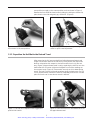
1
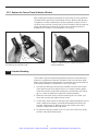
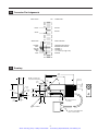
Artisan Technology Group is your source for quality
new and certified-used/pre-owned equipment
• FAST SHIPPING AND
DELIVERY
• TENS OF THOUSANDS OF
IN-STOCK ITEMS
• EQUIPMENT DEMOS
• HUNDREDS OF
MANUFACTURERS
SUPPORTED
• LEASING/MONTHLY
RENTALS
• ITAR CERTIFIED
SECURE ASSET SOLUTIONS
SERVICE CENTER REPAIRS
Experienced engineers and technicians on staff
at our full-service, in-house repair center
WE BUY USED EQUIPMENT
Sell your excess, underutilized, and idle used equipment
We also offer credit for buy-backs and trade-ins
www.artisantg.com/WeBuyEquipment
InstraView REMOTE INSPECTION
LOOKING FOR MORE INFORMATION?
Visit us on the web at www.artisantg.com for more
information on price quotations, drivers, technical
specifications, manuals, and documentation
SM
Remotely inspect equipment before purchasing with
our interactive website at www.instraview.com
Contact us: (888) 88-SOURCE | [email protected] | www.artisantg.com
850F Series Linear Actuators User’s Manual
1.0
Introduction
This manual describes the operation of Newport 850F Series Linear
Actuators. When purchased with a Newport controller, the 850F is fully
compatible with the MotionMaster family of controllers and the PMC200
Series controllers. If you have purchased the 850F for use with your existing Newport controller, please read carefully the section below listing your
controller for compatibility and upgrade information.
2.0
Description
The 850F actuator incorporates a versatile design which can be configured
with travel limits from as little as approximately 1/32 inch to 2 inches
(0.8mm - 50mm), enabling it to be used on a wide variety of Newport translation stages and mirror mounts. Mechanical limit switches cut motor
power preventing accidental over-travel. The actuator incorporates a manual actuation knob for coarse adjustment (with the motor power off).
To provide accurate motion, the actuator’s 3/16 inch diameter plunger is
non-rotating. The standard gearbox ratio actuator can produce a maximum
thrust in excess of 25 pounds (11 kg); but, when operating continuously
over many cycles, the maximum load is rated at 18 pounds (8kg).
The actuator’s internal structure is a precision-rolled leadscrew with a
pitch of 32.3885 threads per inch. The pitch of the leadscrew has been
chosen to provide exactly .05µm encoder resolution when combined with
the standard gearbox ratio (see table section 3.4). Production variations
about this average figure can be compensated by Newport controllers via
software commands allowing the user to limit cumulative, monotonic inaccuracies to within 0.005%. A non-rotating low friction Turcite nut engages
the leadscrew and pushes the plunger. A brass half-nut is used to trigger a
travel limit in the extended position while the lead screw nut trips the
limit at full retraction. The limit switches are repeatable to approximately
40µm.
CAUTION
If the actuator encounters a hard stop within its range of travel
(a translation stage’s or mirror mount’s end of travel for example), a slip clutch releases to prevent damage to the gearhead.
The clutch is designed to slip just below the motor’s maximum
torque. The motor should be stopped as soon as possible to
prevent overheating in this high torque condition.
1
Artisan Technology Group - Quality Instrumentation ... Guaranteed | (888) 88-SOURCE | www.artisantg.com
These actuators are powered by a low inertia DC motor to provide smooth
movement with low acoustic and mechanical noise. Submicron resolution
is obtained with a precision-rolled and electropolished stainless steel leadscrew driven through a low backlash reduction gear. The overall drive
train backlash of ~15µm can be compensated by Newport controllers. Bidirectional repeatability to 1.0 µm can be achieved through this feature.
The motor has an ironless-rotor to permit fast response due to its low
inertia. The brushes are precious-metal plated for long life. The factory
lubrication has a vapor pressure of 10-6 Torr at 25°C.
2.1
Controller Interfaces
The 850F Series actuators incorporate many new features, such as travel
limit switches and manual actuation, not found in previous Newport actuators like the 850, 850A, and 850B Series. Additionally, since the 850F uses a
higher torque motor, the servo parameters required for smooth operation
are different than for previous actuators. For these reasons, controllers
sold before the introduction of the 850F may not be compatible and will
require a special interface adapter. Some controllers have been phased out
and are not supported for the 850F.
2.1.1 MM1000DC/DCS750
The MM1000DC Controller/Driver (formerly DCS750) has been phased out
and is not supported to drive 850F Series actuators.
2.1.2 MM2000 PC Card Motion Controller
The MM2000 controller drives up to four 850F actuators via Newport’s
Universal Interface Box (UIB) P/N 21463-01 and using firmware version 1.4
or later. The controller firmware version may be displayed by using the VE
command. (Note that since the actuators are using the computer’s internal
power supply, there is a limitation of 2 axes which may move simultaneously. Future versions of the UIB will incorporate an external power supply for applications requiring 3 or more axes of simultaneous movement.)
The UIB provides relays to cut motor power for manual knob use and
firmware version 1.4 or later provides commands to properly enable manual positioning and keep track of encoder counts during a manual move.
The UIB may be purchased as an option when ordering an MM2000 controller and the proper version of the firmware is assured. To upgrade an
existing MM2000 controller with firmware version 1.4 or earlier, the UIB
must be purchased separately. The existing firmware may be used with
the following work around for manual actuation. When sending the
MOTOR OFF (MF) command, the I/O bits on the UIB which control the
power relays must be toggled manually using the DEFINE BITS (BO),
CLEAR BITS (CB), and SET BITS (SB) commands. Refer to the MM2000
user manual and the data sheet included with the UIB for more details.
Caution
Failure to manually toggle the I/O bits on the UIB for controllers
with firmware version 1.4 or earlier will leave power applied to
the motor after the MOTOR OFF command has been issued. Do
2
Artisan Technology Group - Quality Instrumentation ... Guaranteed | (888) 88-SOURCE | www.artisantg.com
not try to manually adjust actuator position with power applied
to the motor or damage will result to the gearhead. Manual
positioning should not require more torque to turn the knob
with the actuator cable attached than with it unplugged. If
you’re unsure about the effort required, unplug the actuator to
compare the feel of the knob before proceeding.
2.1.3 MM2000RX Rack Mounted PC Card Controller
Existing MM2000RX controllers are incompatible with the 850F. Factory
upgrades may be done on a special request basis. New MM2000RX controllers may be purchased to be compatible with the 850F on a special
request basis. Please call Newport for the latest information.
2.1.4 MM3000 Motion Controller/Driver
The MM3000 is completely compatible with the 850F Series actuators. All
that is required is to configure the controller with the proper driver card
and adjust the servo parameters per the specifications included in the
controller documentation.
2.1.5 MM4000 Motion Controller/Driver
The MM4000 is completely compatible with the 850F series actuators. All
that is required is to configure the controller with the proper driver card
and adjust the servo parameters per the specifications included in the
controller documentation.
2.1.6 PMC100 Single Axis Controller
Existing PMC100 controllers are incompatible with 850F actuators. Please
call Newport for the latest information regarding upgrades for the
PMC100.
2.1.7 PMC200/PMC200-P Dual Axis Controller
PMC200 Series Controllers using version 3.1 or earlier firmware are incompatible with 850F Series actuators and require an upgrade. The firmware
version is displayed on power up. Please call Newport for the latest information regarding upgrades. PMC200 Series Controllers using version 4.0 or
later are compatible with the 850F Series actuators and include the proper
interface to handle the limit switches and manual knob. Servo parameters
may be set by selecting type 850F in the controller setup menu. There is
also a menu to toggle motor power off for manual positioning. An adapter
cable (P/N 21731-01) must be ordered for each 850F actuator.
3
Artisan Technology Group - Quality Instrumentation ... Guaranteed | (888) 88-SOURCE | www.artisantg.com
Caution
Failure to toggle motor power off before attempting to manually
position the 850F will result in damage to the motor gearhead.
Manually positioning should not require more torque to turn
the knob with the actuator attached than with it unplugged. If
you are unsure about the effort required, unplug the actuator to
compare the feel of the knob before proceeding.
2.1.8 PMC400 Multi-Axis Controller/Driver
The PMC400 Controller/Driver has been phased out and is not supported
to drive 850F Series actuators.
2.1.9 Non-Newport Controllers
If you are using a non-Newport controller/driver please refer to the connector pinout provided. Note that in order to utilize the manual knob feature, power must be removed from the motor (open circuit). Failure to do
so properly may result in dynamic braking on the motor and cause
damage to the gearhead, invalidating your warranty.
3.0
Installation, Set-up, and Operation
The actuators are shipped in sturdy, foam-cushioned boxes. Please inspect
the actuators and/or controllers immediately and notify the carrier if damage is obvious. The actuator includes extra flat head case screws, a
wrench to access the travel limit adjustment and a retaining nut for actuator mounting.
3.1
Setting the Travel Limits
Before mounting the 850F actuator, follow the directions below to adjust
the travel limits such that the actuator will trigger one of its limit switches
before encountering any external hard stop such as the end of travel of a
translation stage. Failure to do this may result in damage to the actuator
and/or the stage. Actuators are shipped with the travel limit set to less
than 1/2 inch (12mm) to prevent accidental over-travel in most instances.
3.1.1 Remove the Coarse Travel Indicator Window
Find a clean flat surface to disassemble the actuator. (Tapped hole optical
tables are not recommended since many of the parts are small and may
drop into the table). Using the manual knob, adjust the actuator to the
4
Artisan Technology Group - Quality Instrumentation ... Guaranteed | (888) 88-SOURCE | www.artisantg.com
zero position as read on the coarse position scale as shown in Figure 1.
Remove the four #2-56 flat head screws holding the indicator window lid,
place them to the side and gently pry off the lid. (Figure 2)
Figure 1 - Remove the indicator window lid with
the actuator in the zero position.
Figure 2 - Approximate travel range markings
assist in quick travel adjustment.
3.1.2 Reposition the Half-Nut to the Desired Travel
After removing the lid, laser marked lines indicating approximate travel
ranges can be seen. Remove the half nut by lifting it from the lead screw.
Note its orientation with respect to the lead screw since it only fits one
way. (Figure 3) Approximate travel is set by replacing the half nut onto the
lead screw with its center scribe mark aligned to one of the markings on
the actuator body. (Figure 4) These marks are only an aid to determining
travel. The half nut may be placed anywhere along the lead screw. For full
2 inch (50mm) travel, remove the half nut completely and store it in a safe
place for future use in case shorter travel is desired.
Figure 3 - The half nut’s ramped corner triggers the
positive limit switch.
Figure 4 - Place the half nut on the leadscrew to set
the approximate travel.
5
Artisan Technology Group - Quality Instrumentation ... Guaranteed | (888) 88-SOURCE | www.artisantg.com
3.1.3 Replace the Coarse Travel Indicator Window
After inspecting the half-nut placement to ensure that it is fully seated on
the lead screw, replace the lid and tighten the four #2-56 screws. Be sure
to tighten the screws completely for proper operation (Figures 5 & 6). If
the lid is loose, the half nut may ride up off of the lead screw at the end of
travel and defeat the purpose of the limit switch resulting possibly in
damage to the actuator or the equipment it is moving.
Figure 6 - Tighten all four screws securely for
proper operation.
Figure 5 - Replace the actuator lid, after seating
the half nut on the lead screw.
3.2
Actuator Mounting
The actuator may be mounted using either the 3/8 inch brass mounting
sleeve or by attachment using the clearance holes in the actuator body.
When using the brass mounting sleeve, the actuator may be mounted to a
wide variety of Newport components in one of four ways:
1. Unscrew the retaining nut and insert the 850F into the mount. Either
use a spanner wrench to tighten the nut, or if space permits, gently
rotate the actuator body while holding the nut stationary with the fingers or a small screwdriver to tighten the whole assembly.
2. When the mount has a set screw, the retaining nut is not used. Just
insert the actuator and tighten the set screw.
3. In rare cases, when neither of the above two mounting methods can be
used, it might be necessary to partially disassemble the device the
actuator is being used in. When access to the retaining nut side is
reached, simply follow method #1 above.
4. For panel mounting in panels up to 1/2” thick, drill a 3/8” hole. Insert
actuator and tighten retaining nut.
6
Artisan Technology Group - Quality Instrumentation ... Guaranteed | (888) 88-SOURCE | www.artisantg.com
3.3
Manual Operation
The 850F is equipped with a knob for manual coarse positioning (except
low speed versions, 850F-LS). Approximate position in both inches and
millimeters can be read using the scales on the window and the scribe
mark on the lead screw nut. A small amount of resistance should be felt
when turning the knob. This is a result of back driving the gearhead motor
assembly and is normal. Attempt to turn the knob smoothly, avoiding
abrupt starts and stops, to minimize the chance of damaging the motor
gearhead. Power to the motor must be off while executing a manual move
or damage may result to the gearhead. If excessive resistance is felt while
trying to turn the manual knob, then check to verify motor power is off. If
you are still unsure, disconnect the actuator cable completely and compare the turning resistance. It should be approximately the same as when
the cable is attached with the motor power off.
Caution
As long as the cable remains attached, the encoder count is preserved and when power is reapplied to the motor, the new
encoder count is updated to be the current position in the controller. Incompatible and non-Newport controllers which do not
properly implement this feature may cause the actuator to jump
to a previous position upon power on and this may result in
damage to the attached equipment if a crash occurs.
3.4
High- and Low-Speed Versions
850F actuators are also available with two alternate speed ranges. This is
accomplished through use of different gearbox ratios and motors with different torque characteristics as listed below.
Model
Standard Speed
850F, 850F-VC
High Speed
850F-HS
Low Speed
850F-LS
Gearbox
Motor
Relative
Speed
Encoder
Resolution
261.409912:1
1624
1x
.05µm
22.0335039:1
1624
~12x
.59321µm
1669.99476:1
1516
~1⁄6x
.00783µm
PMC200 Series Controllers accommodate the differing gear ratios via the
“special” actuator coupling ratio parameter. The procedure for setting this
parameter is documented in your controller’s manual. The coupling ratio
can be calculated by the following simple formula:
Coupling Ratio = 20,000 * gear ratio /262
That is, a standard speed actuator has a coupling ratio of 20,000. Highspeed actuators have a coupling ratio of 1,685.8. Low-speed actuators have
a coupling ratio of 127,768.4. The units of the coupling ratio parameter are
encoder-quadratures-per-millimeter.
For MotionMaster controllers, use the CO command to compensate for the
differing gearhead ratios.
7
Artisan Technology Group - Quality Instrumentation ... Guaranteed | (888) 88-SOURCE | www.artisantg.com
Caution
Actuators with gearhead ratios greater than 485:1 are more susceptible to damage when crashed into a hard stop. For high
gearhead ratios, the motor’s momentum appears to be extremely high when moving at full speed. The mechanical limit switches will prevent a crash due to over-travel, but will not prevent
the actuator from hitting a hard stop within the travel range
(the end of run on a translation stage or mirror mount for example). Be sure to adjust the travel limits (Section 3.1) such that
the limit switches are activated before the actuator reaches the
end of stage travel. A slip clutch has been implemented in the
drive train to minimize the probability of damage if a hard stop
is encountered, but special care should be taken to avoid crashing the actuator.
3.5
Vacuum Compatible Versions
Standard speed 850F actuators can be ordered to operate cleanly within a
vacuum environment. The following describes the alterations that make
the standard actuators vacuum compatible.
The high vacuum model of the 850F Series Linear Actuator, model 850F-VC
incorporates the following features:
1. Six foot Teflon-coated cable from actuator attached to six foot standard
cable.
2. Unanodized aluminum body without label.
3. No fastener sealing compound.
4. The window material is removed.
5. Special lubricant with vapor pressure of 10-6 Torr at 39°C.
6. Vented motor/gearhead/encoder cavities.
4.0
Maintenance and Service
This section describes maintenance and adjustment procedures which
may be performed by the user.
Caution
Do not attempt to adjust the actuator mechanical assembly in
any way other than outlined above (See Setting the Travel
Limits). Any attempt to disassemble the actuator will cause a
misalignment. Call the factory before you try to adjust, repair,
or alter any of the 850F Series actuators without factory-provided instructions. Any unauthorized attempts to adjust, repair, or
alter the actuators or controllers will invalidate your
warranty.
No scheduled maintenance is required for this product. The actuator
should be cared for and handled as any fine instrument. Keep the unit
clean and free of moisture, solvents, or other foreign matter.
Sometimes general wear and tear can cause the actuator’s performance to
degrade, indicating a need for service. Very often such problems as the
actuator moving on its own and the actuator lacking thrust can be
corrected by adjusting your controller’s servo parameters.
8
Artisan Technology Group - Quality Instrumentation ... Guaranteed | (888) 88-SOURCE | www.artisantg.com
Connector Pin Assignments
WIRE COLOR
1
2
3
4
5
6
7
8
9
10
11
12
13
14
15
16
17
18
19
20
21
22
23
24
25
BLACK
WHITE
NC
NC
NC
NC
NC
SHIELD GND
NC
ORANGE
GRAY
YELLOW
GREEN
RED
BLUE
NC
NC
NC
MOTOR +
MOTOR –
SHIELD GROUND
FORWARD LIMIT SWITCH
REVERSE LIMIT SWITCH
CHANNEL A
CHANNEL B
+5 - +12V DC (5ma @ 5V DC)
GROUND
Drawing
CBORE CLR HOLE FOR
1/4-20 (M6) CAP SCREW
0.25
(6.4)
0.31(7.9)
0
MM
IN
5
10
15
20
25
30
35
0
.25
.5
.75
1.0
40
50
1.38
(35.1) 1.00
(25.4)
φ 0.75
(19.1)
1.25
φ 0.187
(4.8)
0.88 MIN
(22.4)
2" TRAVEL
(50)
2.0
2.09 (53.1)
φ 0.59
(15)
φ 0.375
(9.5)
0.52
(13.2)
45°
0.63
(16)
45
0.88
(22.4)
4.84
(122.9)
3.25
(82.6)
1.75
6.0
CONNECTION
PIN
NC
NC
NC
NC
1.5
5.0
0.13
(3.3)
0.44
(11.2)
0.63
(16)
8-32 (M4) CLR HOLE
2 PLACES
3/8-40 THREAD
25 PIN D TYPE CONNECTOR
WITH 12 FOOT CABLE
9
Artisan Technology Group - Quality Instrumentation ... Guaranteed | (888) 88-SOURCE | www.artisantg.com
7.0
Service Form
(Photocopy and return to Newport)
Newport Corporation
U.S.A. Office: 714/ 863-3144
FAX: 714/ 253-1800
Name
RETURN AUTHORIZATION #
Company
(Please obtain prior to return of item)
Address
Country
Date
P.O. Number
Phone Number
Item(s) Being Returned:
Model #
Serial #
Description:
Reason for return of goods (please list any specific problems)
Please complete the below, as appropriate.
List all control settings and describe problem:
(Attach additional sheets as necessary)
Show a block diagram of your measurement system including all instruments connected (whether power is turned
on or not). Describe signal source. If source is a laser, describe output mode, peak power, pulse width, repetition
rate and energy density.
Where is the measurement being performed?
(factory, controlled laboratory, out-of-doors, etc.)
What power line voltage is used?
Frequency?
Variation?
Variation?
Ambient Temperature?
°F. Rel. Humidity?
Other?
Any additional information. (If special modifications have been made by the user, please describe below).
10
Artisan Technology Group - Quality Instrumentation ... Guaranteed | (888) 88-SOURCE | www.artisantg.com
Artisan Technology Group - Quality Instrumentation ... Guaranteed | (888) 88-SOURCE | www.artisantg.com
WORLDWIDE HEADQUARTERS
NEWPORT CORPORATION
1791 Deere Avenue
Irvine, CA 92606
(In U.S.): 800-222-6440
Tel: 714-863-3144
Fax: 714-253-1680
INTERNET
[email protected]
BELGIUM
Tel: 016 402927
Fax: 016 40 2227
GERMANY
Tel: 06151 3621 0
Fax: 06151 362150
ITALY
Tel: 02 924 5518
Fax: 02 923 2448
NETHERLANDS
Tel: 030 6592111
Fax: 030 6592120
SWITZERLAND
Tel: 01 744-50-70
Fax: 01 744-50-77
CANADA
In Canada: 800-267-8999
Tel: 905-567-0390
Fax: 905-567-0392
TAIWAN
Tel: 2-506 2366
Fax: 2-507 9268
FRANCE
Tel: 01 60916868
Fax: 01 60916869
UNITED KINGDOM
Tel: 01635 521757
Fax: 01635 521348
I
FI
REG
ST
RM
Visit Newport Online at: http://www.newport.com
ERE D
Certificate No.: FM 27207
Newport Corporation, Irvine, California, has
been certified compliant with ISO 9002 by
the British Standards Institution.
IN-10955 (1-98)
Printed in the USA on recycled paper
Artisan Technology Group - Quality Instrumentation ... Guaranteed | (888) 88-SOURCE | www.artisantg.com
850F Series
Linear Actuators User’s Manual
Artisan Technology Group - Quality Instrumentation ... Guaranteed | (888) 88-SOURCE | www.artisantg.com
Warranty
Newport Corporation warrants this product to be free from defects in
material and workmanship for a period of one year from the date of shipment. If found to be defective during the warranty period, the product will
either be repaired or replaced at Newport’s option.
To exercise this warranty, write or call your local Newport representative
or contact Newport headquarters in Irvine, California, USA. You will be
given prompt assistance and return instructions. Send the instrument,
transportation prepaid, to the indicated service facility. Repairs will be
made and the instrument returned, transportation prepaid.
Repaired products are warranted for the balance of the original warranty
period or 90 days, whichever is longer.
This warranty does not apply to defects resulting from modification or
misuse of any product or part. This warranty also does not apply to damage from use with a non-Newport motion controller/driver.
This warranty is in lieu of all other warranties, expressed or implied,
including any implied warranty of merchantability or fitness for a particular use. Newport Corporation shall not be liable for any indirect, special,
or consequential damages.
©1995, Newport Corporation
Irvine, California, U.S.A.
IN-10955 (1-98)
ii
Artisan Technology Group - Quality Instrumentation ... Guaranteed | (888) 88-SOURCE | www.artisantg.com
Table of Contents
Page
Warranty ..................................................................................................................ii
Table of Contents ..................................................................................................iii
Specifications .........................................................................................................iv
Section 1 – Introduction ..............................................................................1
Section 2 – Description .................................................................................1
2.1
Controller Interface ...................................................................................2
2.1.1
MM1000DC/ DCS750 ..........................................................................2
2.1.2
MM2000 PC Card Motion Controller ...............................................2
2.1.3
MM2000RX Rack Mounted PC Card Controller .............................3
2.1.4
MM3000 Motion Controller/Driver ..................................................3
2.1.5
MM4000 Motion Controller/Driver ..................................................3
2.1.6
PMC100 Single Axis Controller ........................................................3
2.1.7
PMC200/PMC200-P Dual Axis Controller ........................................3
2.1.8
PMC400 Multi-Axis Controller/Driver .............................................4
2.1.9
Non-Newport Controllers .................................................................4
Section 3 – Installation, Set-up and Operation ................................4
3.1
Setting the Travel Limits...........................................................................4
3.2
Actuator Mounting ....................................................................................6
3.3
Manual Operation ......................................................................................7
3.4
High- and Low-Speed Versions.................................................................7
3.5
Vacuum Compatible Versions ..................................................................8
Section 4 – Maintenance and Service ..................................................8
4.1
Maintenance ...............................................................................................8
Section 5 – Connector Pin Assignments ...............................................9
Section 6 – Drawing .......................................................................................9
Section 7 – Service Form ...........................................................................10
iii
Artisan Technology Group - Quality Instrumentation ... Guaranteed | (888) 88-SOURCE | www.artisantg.com
Specifications
Encoder Resolution
Standard Actuators:
High Speed Actuators:
Low Speed Actuators:
.05000 µm
.59321 µm
.00783 µm
Part Number
850F, 850F-VC
850F-HS
850F-LS
Nominal Gearbox Ratio and Maximum Speed
Standard Actuators:
262:1 ratio (1624 motor); 400 µm/sec.
High Speed Actuators:
22:1 ratio (1624 motor); 4750 µm/sec.
Low Speed Actuators:
1670:1 ratio (1516 motor); 55 µm/sec.
Backlash
< 15 micron typical with external load of
2 lbs (1 kg) minimum
Accuracy
< 0.1% of travel, cumulative
Bidirectional Repeatability
Better than 1 micron when backlash is
compensated by controller (standard
actuators)*
Encoder
Magnetic, 2KHz; open collector,
quadrature output, +5V to +12V supply
Absolute cyclic pitch error
< 1 micron
Time to reach full speed
< 50 msec at max. speed and acceleration
settings
Max. Side Load
5 lb. (2.3 kg) at full shaft extension
Max. Axial Load
18 lb. (8 kg) standard and low speed
actuators
5 lb. (2.3 kg) high speed actuators
Cable
12 foot (3.6 m) cable integral to actuator
terminated with 25-pin male Dsub
connector
Temperature Range
0°F to +120°F
Actuator Case
Black/clear anodized aluminum
Vacuum Compatibility
Special-order vacuum-compatible
versions for operation to 10-6 Torr,
temperature range restricted as stated
above
*Note: Backlash can be compensated by MotionMaster and PMC200 Series
Controllers. Cumulative, monotonic error due to leadscrew pitch
error or mounting errors can be compensated via the CO command
in MotionMaster controllers and the coupling ratio parameter in
PMC200 Series Controllers.
iv
Artisan Technology Group - Quality Instrumentation ... Guaranteed | (888) 88-SOURCE | www.artisantg.com
Artisan Technology Group is your source for quality
new and certified-used/pre-owned equipment
• FAST SHIPPING AND
DELIVERY
• TENS OF THOUSANDS OF
IN-STOCK ITEMS
• EQUIPMENT DEMOS
• HUNDREDS OF
MANUFACTURERS
SUPPORTED
• LEASING/MONTHLY
RENTALS
• ITAR CERTIFIED
SECURE ASSET SOLUTIONS
SERVICE CENTER REPAIRS
Experienced engineers and technicians on staff
at our full-service, in-house repair center
WE BUY USED EQUIPMENT
Sell your excess, underutilized, and idle used equipment
We also offer credit for buy-backs and trade-ins
www.artisantg.com/WeBuyEquipment
InstraView REMOTE INSPECTION
LOOKING FOR MORE INFORMATION?
Visit us on the web at www.artisantg.com for more
information on price quotations, drivers, technical
specifications, manuals, and documentation
SM
Remotely inspect equipment before purchasing with
our interactive website at www.instraview.com
Contact us: (888) 88-SOURCE | [email protected] | www.artisantg.com