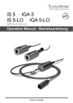
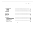
1
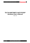
TPT
HB06/08/10 Wire Bonder
Operation Manual
Version 2.00
HB06/08/10 Wire Bonde V2.00
Page 1 of 37
24.01.2005
1. Table of Contents
Page
1.
Table of Contents
2.
List of figures and illustrations
3.
Unpacking and Packing instruction
4.
Safety Instructions
5.
Quick Start 7 Schritte zum Draht Bonden
6.
Introduction
7.
Bonder front view
8.
Bonder back view
9.
tool installation
10. loading bonding wire
11. change halogen lamp
12. User LCD Display System
13. Setup Push Button
14. Bond 1 & 2 Parameter Adjustment
15. Bond Arm
16. EFO System
17. Not used
18. Bonder Installation
18.1 Bonder & Option
18.2 Bonder unpacking
18.3 Dual Fiber Optic
18.4 Mikroscope
18.5 Laser Spotlight
18.6 Tool Installation
18.7 Heated Work Stager
18.8 Power On
18.9 Loading the bonding wire
18.10 Temperature Controller
18.11 Search-Height, Loop-Height & Work-Height
18.12 Bond Parameter
18.13 Tail Parameter
18.14 Control Puck
18.15 Stitch Bonding
19.
Wege Bond Sequence
20.
Ball Bond Sequence
21.
US Generator
22.
Bond Force System
23. "TDSW" Touch down Switch
24.
Wire Clamp
HB06/08/10 Wire Bonde V2.00
Page 2 of 37
2
3
4
5
6
7
8
9
10
11
12
13
14
15
16
17
17
18
18
18
18
18
18
19
19
20
20
20
21
22
23
23
23
24
25
26
26
26
27
24.01.2005
Table of Contents
Page
25.
26.
27.
28.
29.
30.
31.
32.
Motorisised Wire Spool
Bond tool Heater
Trouble Shouting
Bond Tool for HB Bonder
Deep Access 90° Wedge Tool
Packing Instructions
Bonder Specification
Option & Accessories
28
28
29
30
31
32
33
34
2. List of Figurs and Illustrations
Figure
1
2
3
4
5
6
7
8
9
10
11
12
13
14
15
16
17
18
19
20
21
23
24
Page
Bonder front view
Bonder back view
Bond tool installation
Bond wire installation
Changing Halogen Lampe
User LCD System
1 & 2 Bond Parameter
Setup Push Button
N/N
N/N
90° Wedge tool
Bond arm Length
Wedge Bond Sequence
Ball Bond Sequence
Control Puck
EFO System
Heater Stage & Bond Tool Controller
Wire Clamp
Motorised Wire Spool
H26 Heater Stage
Laser Pointer Targeting System
TDSW Touch Down Switch
Bond Tool Heater
HB06/08/10 Wire Bonde V2.00
Page 3 of 37
8
9
10
11
12
13
15
14
31
16
24
25
23
17
20
27
28
19
18
26
28
24.01.2005
3. UNPACKING AND PACKING INSTRUCTIONS
A. Unpacking Instructions
1.
Remove the top layer of protective foam.
2.
Carefully remove all the boxes and bubble wrapped items
containing the bonder accessories from the crate.
3.
Remove all side protective foam
4.
Transfer the bonder to its final work area.
Two people needed for transportation
Do not remove nylon tie wraps, or foam shipping blocks until the bonder
is ready to go into the final work area.
5.
Remove Table Lock Screw
6.
See section “ 5 “ (Page 6) for set-up procedures.
B. Packing Instructions
See Page 32
HB06/08/10 Wire Bonde V2.00
Page 4 of 37
24.01.2005
4. Safety Instruction
1. Read Instruction:
All the safety and operation instructions should be read before the Bonder is
operated.
2. Do not remove Safety Instruction from User Manual
3. When carrying the Bonder around, do not subject the Bonder
to heavy shock or vibration. Two people needed for Transportation
4. The Bonder should be installed on a solid horizontal base
5. Power Sources: The Bonder be operated only from the power source indicated on
the marking label.
The Bonder is equipped with a three-wire grounding plug
Do not defeat the safety purpose of the grounding plug.
6. Protection Circuitry: The Bonder is equipped with two power line fuses at the power
connector
7. The Cover should only be opened after powering down the machine
and removing the power cord from the wall outlet
8. Laser Spot Light, Attention!
Don’t stare into the beam. Direct viewing into the Beam can cause permanent eye
damage. Please note regulations according to EN 60825-1 and VBG 93 Laser class
2, P = 1mW
9. Hot machine parts:
The maximum temperature of heated Work holder is 250°C.
Allowing parts cooling down before replacing Heated Work holder,
illumination lamps or any other hot machine part.
10. EFO ( Electronic Flam Off) Only If Bonder is equip with EFO System
Do not touch the electrode or the wire during bonding or when manually firing the
EFO. The System produces a High Voltage spark. The potential shock hazard is
not usually considered life threatening. However, TPT recommends that those
persons with abnormal heart conditions or artificial heart stimulation devices (e.g.
pacemakers) should not be permitted to operate or service this Bonder.
11. Bonding Tools have sharp edges, beware of touching them.
12. All Service and maintenance should be performed by trained, authorized personnel.
HB06/08/10 Wire Bonde V2.00
Page 5 of 37
24.01.2005
5.1. Quick Start, 7 Step to Wedge Bonding:
1. Unpacking Bonder and Remove Table Lock Screw (Page 4)
2. Install Microscope, Heater Stage, Bond Tool & Bond Wire (P.10 &P.11)
3. Power On Bonder
4. Program 1 in Setup Page 14
5. Height Setup ( Page 21 )
6. Install Bond Wire in Wedge Tool.
7. Start Bond with Button at X-Y Puck (Page 23)
5.2. Quick Start 8 Step to Ball Bonding:
1. Unpacking Bonder and Remove Table Lock Screw (Page 4)
2. Install Microscope, Heater Stage, Bond Tool & Bond Wire (P.10 &P.11)
3. Power On Bonder
4. Program 1 in Setup Page 14
5. Height Setup ( Page 21 )
6. Install Bond Wire in Wedge Tool.
7. Adjust EFO Arc with Set Up Button
Page 17
8 Start Bond with Button at X-Y Puck (Page 23)
HB06/08/10 Wire Bonde V2.00
Page 6 of 37
24.01.2005
6. INTRODUCTION
The HB06/08/10 ultrasonic wire bonder is characterised by vertical feed of wire or ribbon, manual
X-Y control of the work piece, and motorised control of the Z Axis for bond tool.
This manual is designed to provide the operator with an understanding of the equipment operation,
characteristic features of the bonder, adjustments available to insure the best results in wire
bonding, and troubleshooting procedures for fault isolation and correction of malfunctions.
lt is strongly recommended that all operations and maintenance people read this manual
thoroughly, and obtain hands-on operating experience with the bonder. The precision and ease of
operation of the equipment, and quality of the bonding will be better appreciated by using the
bonder. Familiarity will also facilitate expeditious introduction of the equipment in production and
enhance productivity.
HB06 is a manual/ semiautomatic thermosonic wire or ribbon wedge bonder. This bonder was
designed to make 0.5 to 3.0 mil gold or aluminium wire or up to 1.0 x 10. 0 mil gold or aluminium
ribbon electrical interconnections.
HB08 is a manual/ semiautomatic thermosonic wire ball bonder. This bonder was designed to
make 0.7 to 2 mil gold wire electrical interconnections..
HB10 is a manual/ semiautomatic thermosonic wire bonder for Wedge bonding, Ball bonding and
Ball Bumping.
The HB Bonder is characterized by precision mechanism for manual X-Y control of the work
platform and workpiece, a semiautomatic Z control of the bonding tool, and electronic control of the
bonding variables (Force, Ultrasonics, Temperature and Time). Options designed into the HB
Bonder include: Leica 6:1 Zoom Stereo-microscope with 20X eyepieces, and area illuminator; work
stage with mechanical or vacuum clamping provisions. All Bond parameters and programs are
operated with LCD Panel Display. A variety of options are available to enhance operability in
special applications.
Semi Automatic : After press Bond Button and Hold Bond Button, Bond Tool is moving to 1st
Bond Search Height. After release Bond Button 1st Bond is made, and tool is moving To Loop
Height and manual move Y-Distance . After press Bond Button and Hold Bond Button Bond Tool
is moving to 2nd Bond Search Height ,After release Bond Button 2nd Bond is made and Tool is
moving To Start Position ( Work Height )
Manual Mode with Manual Z-Control . The Operator using Manual Z-Control to move Bond Tool to
. Bond surface. After touching Bond surface 1st Bond is made ,Then Operator is moving Bond Tool
by using Manual Z control and X-Y Manipulator to 2 nd Bond Position. After touching Bond Surface
2nd Bond is Made and Tool is rising to Start Position (Work Height )
BASIC ULTRASONIC BONDING
The Model HB06/08/10 employs the basic ultrasonic bonding method. Bonding of two metals using
the ultrasonic method results from three variables: force, ultrasonic energy and time.
•
Force is introduced to promote plastic flow (deformation) and intimate coupling between
the bonding tool, the wire and the substrate.
•
Ultrasonic (62 kHz ) scrubbing displaces surface contaminants and insures
metal to metal coupling.
•
Time is set sufficiently long to cause solid state diffusion.
lf the Model HB06/08/10 is used for gold wire bonding, heat is used as a fourth variable to
eliminate surface contaminants.
HB06/08/10 Wire Bonde V2.00
Page 7 of 37
24.01.2005
7. HB06/08/10 front view
Figure 1
1.
2.
3.
4.
5.
6.
7.
8.
Microscope
Dual Fiber Optic Illuminator
Bond Head
LCD Panel Operator System
Control – Puck
Heater Stage
X - Y-Bondtable,
Manual Z - Lever
1. Heater Stage Conector
2. Not used
3. Tool Heater Conector
HB06/08/10 Wire Bonde V2.00
Page 8 of 37
24.01.2005
8. HB06/08/10 back view
1. Foot switch , Stitch bonding
2. On / Off Switch
3. Power Connector AC 230V Europe T 1,6 A Fuse
AC 115V USA
T 1,6 A Fuse
AC 100V Japan T 1,6 A Fuse
Figure 2
HB06/08/10 Wire Bonde V2.00
Page 9 of 37
24.01.2005
9. Tool Installation
Tool must be flush with the
top of the transducer
5. screw tool with 25 Ncm
Wedge and Capillary in Ball bonding Transducer with Tool Heater
Figure 3
The bonding tool is fitted into the 1/16 inch diameter hole in the ultrasonic transducer and
the top of the wedge tool must be flush with the top of the transducer. Secure by tightening
the special set screw with Torque Wrench 25 cNm.
Wedge bonding Tool:
1/16" dia. x 0.750 long bonding wedge with a '45 wire or ribbon
feed angle is recommended.
Ball Bond Tool :
Capillary 1/16" dia. x 0.450 long is recommended
Refer to your tool supplier catalogue for the tool suitable for the specific application.
HB06/08/10 Wire Bonde V2.00
Page 10 of 37
24.01.2005
10. Loading Wire to Motorised Wire Spool
2-4 Open left cover and tack out spool holder
Place spool of wire in spool mount with the wire
starting end up. Feed the bonding wire
through both wire tension tubes and wire guide
Place motorised wire holder in place
Feed the wire through glass tube above
bonding tool
Move clamp to side
Feed wire through bonding tool
Move clamp back, make sure that wire
is correct placed in clamp
Figure 4
For motorised Wire Spool Maximum Wire Diameter 50µ and Ribbon until 100 x 20µ
HB06/08/10 Wire Bonde V2.00
Page 11 of 37
24.01.2005
11. Change Halogen Lamp 8V 20W
1. Switch Off Bonder
2. remove left and upper housing
3. remove back
4. disconnect cable
5. remove lamp holder
6. change lamp
7.adjust lamp by moving
left and right
8. until light is bright
Figure 5
HB06/08/10 Wire Bonde V2.00
Page 12 of 37
24.01.2005
12. LCD Operator System
Figure 6
1.
Height Adjust
switch for Auto height Set Up ( see page 21)
for 1. and 2. Bond surface
2.
Test USG
switch for test of US -Energy ON / OFF
3.
Clamp
switch for Wire clamp open/closed
4.
Setup
Multifunction Button (Page 14)
Push 1 sec. for Heater Stage & Tool Temperature
n.c. = Heater Stage / Tool Heater not connected
5.
Bond 1
Bond 1 Parameter Adjustment
6.
Bond 2
Bond 2 Parameter Adjustment
HB06/08/10 Wire Bonde V2.00
Page 13 of 37
24.01.2005
13. Setup Multifunction Button
Twist is marking a Function or changing a Value
Push is changing or Enter a new Value
Push Set Up 1 sec. to display Heater Stage & Tool Temperature
n.c. = Heater Stage / Tool Heater not connected
1. Program 1 to 20
2. Bond Type
HB10 Wedge, Ball or Bump Bonding
HB08 only Ball & Bump Bonding
HB06 only Wedge Bonding
3. H- Start 1000µ to 20.000µ
Start Height for Bond Tool
4. H- Loop 0 bis 5000 µ Loop Height
5. L- Tail 0 bis 500µ Tail Length
6. Power EFO 0 bis 100% only at Ball Bonding
HB08 and HB10 Bonder .
7. Temperatur Chuck 0 – 250° C
8. Temperatur Tool
0 – 250°C
9. Bond Counter 0 bis 999
Figure 8
HB06/08/10 Wire Bonde V2.00
Page 14 of 37
24.01.2005
14. Bond 1 & 2 Parameter
Twist is marking a Function or changing a Value
Push is changing or Enter a new Value
Figure 7
1.
Bond 1
Push to activate Bond 1 for Bonding
2.
3.
4.
5.
6.
U/S
Time
Force
Search
Status
Display for 1st. Bond US energy
Display for 1st. Bond time
Display for 1st. Bond force
Display for 1st. search height adjustment
Black = Bond 1 Activate
7.
8.
9.
10.
11.
12
Bond 2
U/S
Time
Force
Search
Status
Push to activate Bond 2 for Bonding
Display for 2nd. Bond US energy
Display for 2nd Bond time
Display for 2nd Bond force
Display for 2nd search height adjustment
Black = Bond 2 Aktiv
To Adjust Bonding Parameter
Twist to Value of change ( US, Time, Force, Search)
Push and twist to change Value
Push to Enter Value
HB06/08/10 Wire Bonde V2.00
Page 15 of 37
24.01.2005
15. Bond arm HB06/08/10 Bonder
12 mm Wedge Bond tool – deep access
200 mm Diameter Work stage
165 mm deep reach transducer
90° Bond Tool
12 mm
Figure 12
HB06/08/10 Wire Bonde V2.00
Page 16 of 37
24.01.2005
16. EFO System ( Ball Bonder HB08 & HB10)
1.
2.
3.
EFO Wand height adjustment
EFO Wand side adjustment
gap between wire and EFO Wand should be
100µ to 300µ for 25µ Wire and
300µ to 600µ for 50µ Wire
DANGER: Do not touch EFO Wand , 750V discharge
4.
5.
LOW für 17µ bis 25µ Draht
HIGH für 30µ bis 50µ Draht
Figure 16
HB06/08/10 Wire Bonde V2.00
Page 17 of 37
24.01.2005
18. Bonder Installation
18.1. Set the HB Bonder on the workbench and remove all tagged shipping blocks,
shipping screws, and tie wrap. All of the shipping provisions may be removed without
disassembly of the bonder.
18.2. Unpack the boxes containing the accessories. Check the contents of these boxes
against your packing list.
18.3 Attach the Dual Fiber Optic arm (Option H55):
Dual Fiber Optic Illuminator: The adjustable dual fiber optic illuminator incorporates
8 volt, 20 watt halogen lamp.
To change lamp open upper and left cover (Figure 5 / Page 12)
18.4 Assemble the microscope to its mounting arm. Install the microscope into the
optical mount of the bonder and secure it in position with the set screw on the right side of
the microscope mount. Figure 1 Page 8
18.5 Laser Spotlight (Option H50)
Mount the Spotlight holder on the Microscope holder Figure 1 (3) (Page 7)
Beam-Distance to Bondlevel is about 100 mm
ATTENTION ! Don’t stare into the beam. Direct viewing into the beam or reflected beam
can cause permanent eye damage. Laser class 2 / Po = 1 mW / r = 635 nm
1. Knob for rough adjustment
2. Screw for fine adjustment
3. Screw for focus adjustment
Figure 21
HB06/08/10 Wire Bonde V2.00
Page 18 of 37
24.01.2005
18.6 Tool Installation
The bonding tool is fitted into the 1/16 inch diameter hole in the ultrasonic transducer and the top
of the wedge tool must be flush with the top of the transducer. Secure by tightening the special set
screw with Torque Wrench 25 cNm.
Wedge bonding Tool:
1/16" dia. x 0.750 long bonding wedge with a '45 wire or ribbon
feed angle is recommended.
Ball Bond Tool :
Capillary 1/16" dia. x 0.450 long is recommended
Refer to your tool supplier catalogue for the tool suitable for the specific application.
Tool Installation Figure 3 (Page 10)
18.7 Heated Work Stage
Plug in the work stage cable into the matching connector.
TPT optional work stage H26 is a heated work stage with provisions for both vacuum clamping and
mechanical clamping. Mechanical clamping provisions allow clamping of work pieces with
dimensions of up to 25 mm. Mechanical clamping adjustments are accomplished with the
adjustable back stop. When the vacuum clamping provision is used, a vacuum hose must be
attached to the work stage vacuum tube to provide a vacuum in the hole in the work stage top
plate.
1. Mechanical clamping
2. Screw to remove plate
3. Vacuum Hose
Figure 20
HB06/08/10 Wire Bonde V2.00
Page 19 of 37
24.01.2005
18.8 Power-On
Before plugging the power cord into the A. C. power source, check the label located on the
rear of the HB Bonder . lf the label does not agree with the available A. C. power, do not
plug in the power cord. Check the A. C. power socket for correct wiring.
POWER ON/OFF Switch is on back left side,
LCD Display light on indicate that POWER is on.
18.9 Loading the Bonding Wire in the Motorised Wire Spool
Open left cover and tack out spool holder
Place spool of wire in spool mount with the wire starting end up.
( Install Wire Guide Glass tubes in Wire Spool Holder and Bondhead Fig. 4 Page 10 )
Feed the bonding wire through wire tension tubes and wire guide
Place motorized wire holder in place
Feed the wire through glass tube above bonding tool
Move clamp to side
Feed wire through bonding tool
Move clamp back, make sure that wire is correct placed in clamp
For motorised Wire Spool Maximum Wire Diameter 50µ and Ribbon until 100 x 20µ
Figure 4 Loading Bonding Wire (Page 11)
18.10. Temperature Controller for Work Stage & Tool Heater
only at Gold Wire 120°C – 150°C
Figur 17
Twist is marking a Function or changing a Value
Push is changing or Enter a new Value
Push Set Up 1 sec. to display Heater Stage & Tool Temperature
n.c. = Heater Stage / Tool Heater not connected
HB06/08/10 Wire Bonde V2.00
Page 20 of 37
24.01.2005
18.11 Adjust Search height, Loop height and Work height
A: Push “Height Adjust” Button: see page 13
Work-Height is set automatic to 25000 after Bond le vel
Press Start Button on Control-Puck ( Page 23 Figure 15 )
Bondtool is moving to 1 st Bond level .
Measured Height is Displayed and automatically saved
Press Start Button on Control-Puck ( Page 23 Figure 15 )
Bondtool is moving to 2 nd.Bond level
Measured Height is Displayed and automatically saved
B. Adjust Search height 1 st Bond = height tool stop before 1 st.bond
Twist to Search at Bond 1
Push and twist to change Value
Push to Enter Value
C. Adjust Search height 2 nd.Bond = height tool stop before 2 nd.bond
Twist to Search at Bond 2
Push and twist to change Value
Push to Enter Value
D: Adjust Loop Height = Height Bond tool rise after 1 st Bond
Twist “Set Up” Button to H - Loop
Push and twist to change Value
Push to Enter Value
C: Adjust Work height = Height Bond tool rise after 2 nd Bond
Twist “Set Up” Button to Start - Height
Push and twist to change Value
Push to Enter Value
HB06/08/10 Wire Bonde V2.00
Page 21 of 37
24.01.2005
18.12 Adjust Bonding Parameter
Push Bond 1 or 2
Twist to Value of change ( US, Time, Force, Search)
Push and twist to change Value
Push to Enter Value
U/S Energy 0 to 1000 mW programmable
Time 15 to 5000 millisec. programmable
Force 15 to 100 cNm programmable
Starting Parameters
Table below shows initial set-up parameters only. Actual parameter values will vary
depending on process, materials and specific applications.
Bond Wire:
WEDGE Bonden
.7 Mil
17µ
1.0 Mil
25µ
2 Mil
50µ
US Energy
1st
2nd
150
180
220
280
400
400
Time
1st
2nd
150
150
200
200
200
200
Force
1st
2nd
20
20
30
30
40
40
Temperature
120°C
120°C
120°C
Wedge Tool: 19 mm Length, Hole Diameter
38µ
38µ
102µ
.7 Mil
17µ
1.0 Mil
25µ
Bond Wire:
Ball Bonden
2 Mil
50µ
US Energy
1st
2nd
150
180
200
350
300
400
Time
1st
2nd
150
150
200
200
200
200
Force
1st
2nd
100
100
300
300
40
40
Temperature
120°C
120°C
120°C
Kapillare Tool: 11,1 mm Length, Hole Diameter
25µ
38µ
89µ
HB06/08/10 Wire Bonde V2.00
Page 22 of 37
24.01.2005
18.13 Adjust Tail Parameter
Twist “Set Up” Button to “Tail”
Push and twist to change Value
Push to Enter Value
18.14 Control Puck & Bond Operation Sequent
Figure 15 Control Puck
1. Bond Start Button
2. Tail Feed Back
3. Tail Feed Forwards
18.15 Stitch Bonden
When the stitch Foot switch is actuated before second bond, the bonder will not terminate
the bonding cycle after the second bond. Rather, the clamps remain open allowing
additional bonds to be completed. As long as the stitch switch is depressed, the stitching
will be continued . When the switch is released, the next bond will be the terminating bond.
HB06/08/10 Wire Bonde V2.00
Page 23 of 37
24.01.2005
HB06/08/10 Wire Bonde V2.00
Page 24 of 37
24.01.2005
5. Operator positions 2nd target
under spotlight
1. Start Position
Operator positions target under
spotlight. Clamp is closed
7.Tool rise to programmed
Work height position
3. Operator releases Control Puck
Start button
Bond tool descends to 1st. Bond
TDSW activate all Bond
Parameters
19. Wedge Bonding Sequence
Figure 13
6.Operator holds down Control Puck
Start button. Bond Head travels down
to 2nd .search height. Operator
repositions target if necessary..
Operator releases Control Puck Start
button. Bond tool descends to 2nd
Bond .TDSW activate all Bond
Parameters
2. Operator holds down Control
Puck Start button
Bond Head travels down to
1st.search height
Operator repositions target if
necessary.
8. Clamp moves Wire to
programmed Tail length position
4. clamp opens and tool rise to loop
height
HB06/08/10 Wire Bonde V2.00
Page 25 of 37
24.01.2005
3. Operator releases Control Puck
Start button
Bond tool descends to 1st. Bond
TDSW activate all Bond
Parameters
20. Ball Bonding Sequence
Figure 14
7. Tool rise to programmed
Work height position
2. Operator holds down Control
Puck Start button , Clamp opens
Bond Head travels down to
1st.search height
Operator repositions target if
necessary.
6. Operator holds down Control Puck Start
button
Bond Head travels down to 2nd .search height
Operator repositions target if necessary.
Operator releases Control Puck Start button
Bond tool descends to 2nd Bond
TDSW activate all Bond Parameters
1. Start Position
Operator positions target under
spotlight. Clamp is closed
5. Operator positions 2nd target
under spotlight
9. EFO Wand moves under Tail (Wire
end) and forms Ball
4. after Bond tool rise to loop height
21. Ultrasonic Generator
The signal from the logic control circuit, the ultrasonic generator provides 62 kHz power to
the transducer at a level set on program. The ultrasonic energy is applied until the bond
time is complete. (PLL) phase loop lock system is provided to insure work piece coupling,
and to maintain transducer operation at the specified frequency.
22. Force system
The force generator provides current to effect the bond force. On signal from the logic
control circuit, the current is provided to the force solenoid in a ramped fashion until the
preset level is reached. At this level the power is held until the bond time is over. The force
level and bond time are preset by the front touch panel controls.
23.TDSW Touch down switch adjustment
Figure 23 TDSW Touch Down Switch
1. TDSW Touch Down Switch
2. Loosen screw on side and adjust cap between Bond arm and TDSW
with Set screw until yellow (2) light is ON = No touch down
HB06/08/10 Wire Bonde V2.00
Page 26 of 37
24.01.2005
24. Clamp Force and gap Adjustment
There is no convenient way to measure the clamp force. The user must therefore be alert
to deformation of the wire to identify excess force. When force is inadequate, the wire
clamps will not hold the wire in the tool during closed clamp conditions or will not break the
wire after second bond.
Figure 18
1. Clamp gap adjustment
2. Clamp force adjustment
3. Clamp Position adjustment
HB06/08/10 Wire Bonde V2.00
Page 27 of 37
24.01.2005
25. Motorised Wire Spool
Figure 19
1. Adjustment for run time of motor ( clock wise = more time )
2. Adjustment for sensibly of start sensor ( clock wise = less sensible)
26. Tool Heater
Figure 24
Option H40 Tool Heater with Temperature Controller
Option H41 Spare Tool Heater with Thermocouple
HB06/08/10 Wire Bonde V2.00
Page 28 of 37
24.01.2005
27. Troubleshouting
Troubleshooting for bonding problems see section
“Wire Bond Technology”
HB Bonder technical problems:
Symptom / Error Mesage
Cause / Corrective Action
A. No Bond Head movement
switch Bonder Off/On
Adjust TDSW switch (Page 29)
B. No Ball after Bond
Check if in Menu Bond Mode Ball is ON
Check gap between wire and EFO Wand
( for 25µ wire 100 to 400 µ )
D: Tail is moving sideways
under Wedge Tool
Tool longer as 19 mm
Hole in Wedge to big
Clamp defect
Wedge defect
E: Error no USG found using Demo Mode
Transducer not connected on US Board
US Board Defect
D-Sub Connect Bond head not connected
24V missing
Motherboard Defect
H. Display Freezes after Power on
and touching „ Setup“ button
The cause is TDSW is not closed
( not closed LED OFF )
A: to less Static force,
adjust static force to 20g to 25g
see page 28 Reed wheel #1
B: TDSW gap is to big,
adjust TDSW gap see page 29 user manual
C: No free movement of Transducer
Transducer can not go to upper position
Check mechanical parts for free movement
HB06/08/10 Wire Bonde V2.00
Page 29 of 37
24.01.2005
28. Bonding Tools for HB Wire Bonder:
Capillary:
Wedge
25µ Wire
50µ Wire
41413-0010-334
41413-0020-334
Micro Swiss 11.10 mm Tool length
Micro Swiss
25µ Wire
25µ Wire
1572-15-437 GM
1572-15-750 GM
Gaiser 11 mm Tool length
Gaiser 19 mm Tool length
50µ Wire
1572-35-437 GM
Gaiser
25µ Wire
50µ Wire
4445-1520-3/4-CG-F
4445-3540-3/4-CG-F
Gaiser
Gaiser
20 x 100 µ Ribbon 4645R-.8-4-3.0-3/4-CG
HB06/08/10 Wire Bonde V2.00
Page 30 of 37
Gaiser
24.01.2005
29. Deep Access 90° Wedge Tool
Wire Clamp
Bond Wire
Wedge Tool
Bond-Surface
Figure 11
HB06/08/10 Wire Bonde V2.00
Page 31 of 37
24.01.2005
30. Packing Instructions
1.
Remove from Bonder:
A. Bondtool ( wedge, Capillary )
B. Bond Wire
C. Glass wire Guide
D. Dual Fiber Optic Illuminator
E. Microscope with Holder
F. Laser Spot light targeting system
G. Heater Stage
I. and any other options from Bonder.
2.
2
Secure the work plate by inserting the Table Lock Screw.
Tighten softly the screw to secure the work plate.
3
3.
4.
5.
Secure Display with Carton
Secure Tower-Cover with soft foam
Secure between Transducer and clamp with foam
6.
Carefully move Bonder in wooden box
4
Pack accessories (i.e., work stage, microscope, illuminator,
eyepieces, etc.) in bubble wrap in separate boxes.
Position these items at suitable locations around the sides
Of the bonder so that they are secure from movement and
so the to foam cover can be installed.
7.
Place the foam cover around and over Bonder .
5
8.
Position and bolt the wooden cover on to the crate.
6
HB06/08/10 Wire Bonde V2.00
7
8
Page 32 of 37
24.01.2005
31. Specification
The HB06/08/10 is a bench top size wire bonder, easy to operate and ideal for laboratories,
pilot and pre-production runs and small scale production lines. One Deep-access 90° Bond head for wire
and ribbon bonding. No hardware change necessary. Easy operation with LCD Panel Operator System.
PLL Ultrasonic generator, Stitch bonding, 20 Program storage capacities
Heater stage and Tool Heater Controller. Motorised 2” Wire Spool and Motorised Wire Clamp.
Technical specifications
Ultrasonic system
Utrasonic power
Bond time:
Bond force:
:
62 kHz transducer, PLL Control
0 - 2 watt output
15 - 2000 msec.
15 - 100 grams
Gold and Aluminium wire ∅
Gold ribbon
Motorised Wire Spool
Wire termination
Wire feed angle
Motorized Z travel
Throat depth
Fine Table motion
Mouse ratio
Temperature controller
17 to 76µ ( 0,7 to 3 mil )
up to 25 x 250µ ( 1x 10 mil)
50,8 mm ( 2 inch ) Option
Clamp tear
90° for Wire and Ribbon
15 mm
165 mm ( 6,7”)
10 mm (0,55 “)
7:1
up to 250°C +/- 1°C
Electrical Requirements
Operating temperature range
Physical Dimensions
Weight
Industry Standard
100 – 120 / 220 - 240V +/-10% 50/60 Hz 10A max.
18°C – 32°C
680 mm W x 640 mm D x 490 mm H
Net 50 kg
CE standard
NOTE: These specifications are subject to change without prior notice.
HB06/08/10 Wire Bonde V2.00
Page 33 of 37
24.01.2005
32. Option & Accessories
H10 Zoom Stereo-Microscope Leica S6 20x
H12 Zoom Stereo-Microscope Leica MZ6 16x
H13 Zoom Stereo-Microscope Leica S4 20x
H15 HP 155-350 Hotplate, 155 x 155 mm
H21 Adjustable height heated work stage surface 100 x 100 mm
H25 Adjustable height work stage surface 60 mm diameter
H26 Adjustable height heated work stage surface 60 mm diameter
H26-TO Top-Plate für TO5 & TO8 for H26
H26-DIL Slotted Top Plate für DIL for H26
H29 Adjustable height heated work stage surface 90 mm diameter
H30 Additional Soft & Hardware for Ball/Wedge Bonding
H35 Loop Profile Software
H40 Toll Heater and Temperature Controller with LCD Display
H41 Spare Tool Heater with Thermocouple
H50 Spotlight targeting System
H51 Manual Z-Control
H55 Dual Fiber Optic Illuminatorr
H56 US High/Low Automatic Switch for 1 or 2 Watt
H57 1-2-2.. & 1-2-1.. Stitching capability
H60 Bonding tool Wedge
H61 Bonding tool Capillary
H65 Unplugging Probe for Bondtool
H66 Tungsten Wire for Unplugging
H70 Gold-Wire 25µ, 60 Meter, 2" Spool
H71 Motorised Wire Spool
H72 ½“ Wire Spool Adapter
H73 Torque Wrench 25cNm for Bonding Tool
H74 Aluminium -Wire 25µ, 60 Meter, 2" Spool
H80 Leica ICA Videomodul fit to Mikroskop MZ6
H82 Shipping Crate
H83 Side View Video Camera (without Monitor)
H84 13” TFT Monitor
H85 Hitachi Color Video Camara
H86 External Temperature Controller for Work Stage
H87 Cross hair generator
H88 TFT 13“ Monitor
H89 Video-Targeting-System
PT101 Manual Pull-Tester for testing of wire bonds
PT03 Micro-Hook for PT101 Pulltester
PT04 Workholder 60 mm Dia. for PT101
PT11 Destruct Pull Tester 2 – 15 cN
PT12 Destruct Pull Tester 3 – 30 cN
PT13 Non-destruct Pull Tester 3-7cN
5-SA Tweezers
HB06/08/10 Wire Bonde V2.00
Page 34 of 37
24.01.2005
H10
H12
H13
H15
H21
H25 / H26
H26-TO
H26-DIL
H29
H30
H35
H40
H50
H51
H55
HB06/08/10 Wire Bonde V2.00
Page 35 of 37
24.01.2005
H56
H57
H61 / H60
H65
H66
H70
H71
H72
H73
H74
H80
H82
H83
H84
H85
HB06/08/10 Wire Bonde V2.00
Page 36 of 37
24.01.2005
H86
H87
H89
PT101
PT11 / PT12
PT13
PT03
PT04
5-SA
HB06/08/10 Wire Bonde V2.00
Page 37 of 37
24.01.2005