1
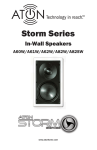
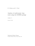
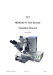
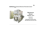
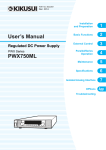
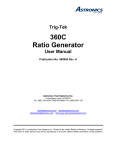
User’s Guide to Panchawati, Off Pashan Road, Pune – 411008 September 2013 Version 2.0 Centre for Materials for Electronics Technology Contents 1. What is LTCC? ..... 01 2 LTCC Fabrication Process and Materials ..... 03 3 C-MET Materials Selection and Process Choices ..... 07 3.1 Materials Selection ..... 07 3.2 Specific Process Choices ..... 09 3.3 C-MET’s Current Process Limitations ..... 11 Annexure I Present Equipments & Capabilities ..... 12 User’s Guide to LTCC and C-MET’s Fabrication Facility 1. Version 2.0 What is LTCC? The Low Temperature Co-fired Ceramic (LTCC) is a multilayer interconnects fabrication process that uses glass-ceramic tapes and conducting pastes for preparing the circuits. The process ultimately produces multilayer ceramic circuits, quite similar to the multilayer printed circuit boards with solder-attached active and passive components on the outer surfaces, with some differences. The LTCC multilayer circuits are much denser and offer far better electrical properties. The use of glass-ceramic material allows reduced co-firing temperature to below 900oC compared to the conventional ceramic firing temperatures. This permits use of Ag, Au and their alloys for interconnections which offer better stability during processing and are better conductors. Such low firing temperature also allows use of other standard functional materials (such as, those for resistors, capacitor dielectrics etc) within the structures, which is a major advantage. By virtue of such capabilities, LTCC enjoys significant advantages in terms of package size, reliability, cost and manufacturability over the other multilayer circuit fabrication processes. Figure 1.1 presents a schematic representation of typical LTCC package. Co-fired / Post- fired Resistor Conductor Line Cavity Via Buried resistor Buried capacitor Figure 1.1: Schematic of LTCC Structure showing its capability to integrate with active devices In summary, the specific advantages of LTCC can be listed as below: • Reliable packaging due to ceramic processing • Multilayer or 3D circuit capability which is virtually unlimited • Low dielectric loss and better control over dielectric properties • HF capabilities in microwave and millimeter wave frequency range • High density integration due to smaller via and inclusion of buried passive elements Electronic Packaging Group, C-MET, Pune 1|Page User’s Guide to LTCC and C-MET’s Fabrication Facility Version 2.0 • Capability of packaging of Si chips along with any other technology devices • Hermetic sealing capability • Can handle fluidic, optical, mechanical and electrical signals simultaneously • Microsystems - devices can be packaged as well as fabricated in LTCC • Close thermal expansion coefficient to Si, GaAs allowing direct attachment of chips • Compatibility with flip chip, wire bonding and SMT processes The following may be listed as disadvantages of LTCC, although not all would matter in an intended application: • High shrinkage after co-firing and its tolerance cause process difficulties • Limited range and high tolerance for buried passive components due to materials limitations • Higher cost than polymeric packages • Low thermal conductivity of tapes as compared to ceramic materials • Non-flexible packages Fortunately, there are ways to overcome some of the disadvantages. For example, the heat can be routed through thermal via to the outer world, thereby circumventing the difficulty of relatively low thermal conductivity. Next, there are some special processing methods which can make the shrinkage as low as zero in XY direction. More discussion about some of the process and applications related issues can be found further in this document. Electronic Packaging Group, C-MET, Pune 2|Page User’s Guide to LTCC and C-MET’s Fabrication Facility Version 2.0 2. LTCC Fabrication Process and Materials The LTCC green tapes are prepared by uniformly casting the inorganic powder into polymeric materials using tape-casting technique. The slurry of the casting material is composed of glass-ceramic mixture or composites in binders and organic solvent. This as-prepared slurry is cast to obtain glass/ceramic ‘green’ tape and is put together over a Mylar support. These tapes are now commercially available. The circuit/ package preparation process starts with cutting of green tape to the required processing size and pre-baking at a specified temperature. This step is, however, not mandatory. After pre-conditioning of tapes, the package fabrication is initiated by preparing via holes, cavities and alignment holes on each single, individual layer, separately. The via holes are usually prepared by either mechanical punching, or laser cutting process and the diameter varies typically between ~100µm and 250µm. Same processes are used for creating cavities, which may vary from a few mm to a few 10's of mm in size, depending upon the design. The via are intended to be used as electrical connections. Between layers are then filled with silver or gold paste, either by stencil printing method or by pressurizing the paste into the via holes. The stencil printing is done using a hard polymer squeeze while vacuum is applied below the sample. Once via are filled, usual thick film screen printing is then employed to print metallization layer and buried passives. The minimum line width of the printed conductors is usually about 100µm. Each single layer then passes through an optical inspection. Next, all such individually processed layers are aligned with help of registration pins, and stacked after removing the supporting mylar sheet. This method gives registration accuracy within 20µm. Automatic alignment is also employed sometimes, which gives slightly better alignment accuracy of about 10µm. After cutting off the registration area, whose utility is now over, the stacks are laminated using uni-axial heated press or an Isostatic laminator. The latter process is usually preferred due to its ability to retain cavity and via shapes. The individual circuits on the tiles are then singulated and co-fired at 850-900°C peak temperature following the manufacturer-recommended firing cycle. Sometimes, singulation is done after co-firing using diamond wheel cutting machine. The main Electronic Packaging Group, C-MET, Pune 3|Page User’s Guide to LTCC and C-MET’s Fabrication Facility Version 2.0 characteristic of sintered LTCC package is its all round shrinkage. Free or un-constrained sintering offers approximately 12-16 ± 0.3% and 15-25 ± 0.5 % shrinkage in X/Y and Zdirection respectively, depending on the composites used for preparation of LTCC green tape. The integrated LTCC substrate is then available for post-fire processing, which may include usual print-fire sequences for brazing, attachment of external components, BGA preparation etc. After the completion of all such processing, the substrate is ready for chip attachment and sealing. Figure 2.1 presents the common process sequence for the preparation of LTCC structures. Commercially, different types of tape systems are available, and there are a good number of manufacturers. DuPont, ESL, Ferro, Hearaus, Nikko, and Northrop Grumman, are amongst the representative names. All the commercial products are usually having similar properties, with differences in their dielectric constant, loss tangent, thickness and shrinkage. A partial list of commercial tape systems is presented in Table 2.1. One important point regarding LTCC materials is worth mentioning. All the commercial LTCC tapes have to be used with the compatible pastes or tapes made available by the same manufacturer. Here, by compatibility one mean that the shrinkage and 'materials interaction' properties (especially during firing) have to be tailored to match with each other. Therefore, due to the uncertainty about compatibility issues and thus, the final properties, mixing of materials system from different manufacturers is generally avoided. Electronic Packaging Group, C-MET, Pune 4|Page User’s Guide to LTCC and C-MET’s Fabrication Facility Version 2.0 Green Tape Green Tape Pre-conditioning "Layer 1" Via Punching "Layer 1" Via filling & Conductor printing "Layer 2" Via Punching "Layer 2" Via filling & Conductor printing "Layer n" Via Punching "Layer n" Via filling & Conductor printing Inspection Stacking “1 to n” Layer Lamination Co-firing Post fire Processes Dicing Final Package Figure 2.1: Process steps for manufacturing of LTCC modules Electronic Packaging Group, C-MET, Pune 5|Page User’s Guide to LTCC and C-MET’s Fabrication Facility PROPERTY Version 2.0 DuPont 951 FERRO A6M FERRO A6-B EMCA T8800 HERATAPE CT700 Motorol a T2000 DuPont 943 Blue White Black Blue Blue White Blue 3.7, 5.2, 8.2 7.8 3.7, 7.4 3.3,6.7 3.5-15 3.8 4.5 5.9 6.5 7.2 3.6, 5.7, 7.9 7.9 9.1 7.5 0.15% - <0.2% .18 <0.5% <.35 <0.2% <.5 <0.2% - <0.3% - <0.1% 0.12 >1012 Ohms >1000 V/Mil - >1012 Ohms >1000 V/Mil <1 µamp/cm2 17.1 >1012 Ohms >1000 V/Mil - >1012 Ohms >1000 V/Mil - - - >2x10¹² Ohms >1100 V/Mil - 28.3 >1012 Ohms >900 V/Mil <1 µamp/cm2 17.1 40.6 - 36 33.4 15 12 12 27 - - - .17 3.1 2.5 2.5 3.06 3.1 3.13 3.2 5.9 <10 µ in 7.5 <15 µ in 9-10 6.0 6.7 <15 µ in <15 µ in <22 µ in Conforms to setter 5.6 - 6.0 - X,Y Shrinkage 13±.2% 15±.2% 14.5±.2% 12±.2% 15±.2% 10.9% 9.5±.3% Z Shrinkage Metallization 15±.5% Au/Ag – Ag -Au 25±.5% Au/Ag – Ag -Au 35±.5% Au/Ag – Ag -Au 14±.5% Au/Ag – Ag -Au 25±.5% Au/Ag – Ag - Au 14.7% Au/Ag – Ag -Au 10.3±.5% Au/Ag - Ag -Au Colour Available Fired Thickness (Mils) Dielectric Constant (K) Loss Tangent µ-wave Insertion Loss (dB/in) @ 10GHz Insulation Resistance Breakdown Voltage Electrolytic Leak Current Flexural Strength (kpsi) (3 point test method) Young’s Modulus (kpsi) Poisson Ratio Fired Density (gm/cc) TCE (ppm/°C) Surface Roughness Camber - Table 2.1: Tape properties of various LTCC tape manufacturers Electronic Packaging Group, C-MET, Pune 6|Page User’s Guide to LTCC and C-MET’s Fabrication Facility Version 2.0 3. C-MET Materials Selection and Process Choices As the previous section briefly describes, the generic LTCC process offers several choices at individual process steps. Likewise, one has to choose from a host of materials systems that are commercially available. This section provides a brief description of such choices made by C-MET while setting up the LTCC process, and reasons behind making certain choices. 3.1 Materials Selection The selection of the tape system and its manufacturer has to be done carefully, depending upon the requirements of the targeted applications. For C-MET the choice of applications is wide, ranging from devices, device packaging, HF circuits, biomedical applications etc. Therefore, a tape system that is most suitable for all the possible applications was required to be selected. C-MET has presently chosen the DuPont 951 tape system for its LTCC operations because of its versatility, wide acceptance and availability of a wide range of materials for buried components, brazing etc. Additionally, this tape system provides option of Ag, Au and mixed metal system for the conductor fabrication. Further, the DuPont materials are easily available in India. Annexure-1 provides the list of complete set materials available for the 951 Green Tape system along with their intended application. Amongst the available materials with the 951 Green Tape systems, C-MET usually keeps stock of the Ag based materials, along with the Au based wire bondable conductor paste. C-MET also keeps the brazing and some low-value resistor materials. Table 3.1.1 provides the complete list of materials usually available ex-stock at C-MET. Other compatible materials are purchase as and when need arises. Electronic Packaging Group, C-MET, Pune 7|Page User’s Guide to LTCC and C-MET’s Fabrication Facility Material No. Version 2.0 Material type Green Tapes 951 PX 250 micron green tape 951 PT 100 micron green tape 951 C2 50 micron green tape Pastes 6141 Conductor Paste for via filling 6142D Inner Conductor Paste 6146 Outer Conductor Paste CF011 Resister Paste 6135D Solderable conductor Paste(Post fire) 6138 Outer Conductor Paste QQ550 Encapsulant Paste 4195 Encapsulant Paste CF021 Resister Paste 5092 D Resister Paste 9615 Dielectric Paste 5081 Conductor Paste (adhesive brazing) 5082 Conuctor Paste (barrier brazing) 5742 Solderable conductor paste 5087 Brazing Conductor paste Post fire Soldering ,Sealing ,brazing & BGA pair attachment material 90Pb-10Sn Soldering Paste (Type IV) 99Sn-1Sb Soldering Paste(Type III) 63Sn-37Pb Soldering Paste Solder 96.5Sn-3.5Ag Ribbon (1*0.004) Solder Preforms 96.5Sn-3.5Ag [(2*0.512*0.413)*0.004] Solder Spheres for BGA 90Pb-10Sn (0.030mm dia.) Kovar Pins 0.45mm dia.,0.85mm head dia.,10mm length Ni/Au Plated Table 3.1.1: LTCC materials usually available at C-MET. Other materials in this tape system can be purchased specifically for a particular implementation Electronic Packaging Group, C-MET, Pune 8|Page User’s Guide to LTCC and C-MET’s Fabrication Facility Version 2.0 3.2 Specific Process Choices C-MET has also made her own choices for processes. Firstly, C-MET chose the about 6×6″ tape format providing 4×4″ tile area for circuit fabrication. This aspect is based upon the available formats at the time of selection, the size expectations for various applications and the cost of equipment for processing these tapes. The aim of the facility of being a “Prototyping Centre” for LTCC, was the guiding factor. Table 3.2.1 provides details of available process choices for each process, the choice made by CMET and the reasons of such selection. Annexure–I provides list of equipment used for LTCC process along with their important features and specifications. Sr Process Process Options C-MET Choice Design • Standard CAD tools • Specialized LTCC design software Standard CAD tool and Specialized LTCC design software Tape shaping • Purchase cut sheets • Buy roll-cutting machine Purchase cut sheets Saves investment on blanking machine Via formation • Laser punching • Programmable punching LASER punching and Programmable punching LASER punching allows better flexibility in via sizes. 4 Inspection • Microscope • Automated Optical Inspection Microscope and Automated Optical Inspection 5 Via filling Pressurized chamber and Stencil Printing 6 Conductor formation • Pressurized chamber • Stencil printing Opening of via and via edge quality etc can be verified. The punched design can be directly verified with the original design using AOI Flexibility of process Availability of Screen/stencil printer • Screen printing Screen printing --- 1 2 3 7 Stacking • Automatic video alignment • Pin-based alignment 8 Stack shaping • Heated blade Electronic Packaging Group, C-MET, Pune Automatic alignment and Pin-based alignment with auto-stacking Heated blade Remarks Standard CAD tool is useful in designing packages, but only the Specialized LTCC design software can handle large number of interconnects dense circuits and layers with Automatic DRC Better alignment accuracy available with automatic alignment --9|Page User’s Guide to LTCC and C-MET’s Fabrication Facility Version 2.0 Punching of various geometries/ shapes of various sizes is possible with the help of LASER & CNC. Power press with die-punch assembly can be used for high volumes Parallel plate lamination provides option for laminates without cavities, Isostatic lamination gives better quality, ability to prepare buried and closed cavities Both have individual advantages depending on the end product requirement. Open or buried cavity formation • Laser cutting • CNC milling • Punching using power press LASER cutting, CNC milling and punching using power press 10 Lamination • Parallel plate lamination • Iso-static lamination Parallel plate lamination and Iso-static lamination 11 Singulation • Green stage cutting • Post-fired cutting Green stage cutting and postfired cutting 12 Co-firing • Free firing • Constrained firing • Press-sintering Free firing and press-sintering Both choices expands flexibility 13 Resistor trimming • LASER trimming • Buried resistor trimming Both, LASER and Buried trimming Provides complete flexibility to the designer for placing low tolerance resistors 14 Contact formation • BGA formation • Pin attachment (KOVAR) • Wire bonding BGA formation and Pin attachment Capability to have large number of interconnects 15 Tube attachment • Soldering • Brazing Soldering and brazing 16 Chip attachment and connections Provides complete flexibility to tube attachment • Filp-chip bonding / Face-up bonding --- Not available yet 17 Hermetic Sealing • Seam sealing • Solder sealing • LASER sealing Seam and solder sealing 18 Inspection after firing • X-ray inspection X-ray tomography 9 LASER sealing is required in only certain applications, such as using SS lids etc. The two choices made here cover most other applications In-situ inspection of the fired samples. Nondestructive inspection is possible for alignment verification or other issues. Table 3.2.1: Process choices made by C-MET Electronic Packaging Group, C-MET, Pune 10 | P a g e User’s Guide to LTCC and C-MET’s Fabrication Facility Version 2.0 3.3 C-MET’s Current Process Limitations The description in Table 3.2.1 above indicates that C-MET has already established a fullfledged LTCC processes for most of multilayer LTCC design can be implemented. With the availability of such facilities and processes, there are a very few limitations, which are listed in the following. • Passive and active device placement and attachment: Presently, the LTCC multilayer circuits or packages can be fabricated, but circuit or package cannot be assembled / populated with passive / active components as C-MET does not have any SMT pick and place machines and chip attachment facilities. • Laser Sealing: Presently only seam and solder sealing are available. LASER sealing is useful for applications such as pressure sensors, where stainless steel may be required for sealing. Recently, new, advanced machines have been inducted in C-MET's facility, which has significantly eliminated many of the limitations. Electronic Packaging Group, C-MET, Pune 11 | P a g e User’s Guide to LTCC and C-MET’s Fabrication Facility Version 2.0 Annexure I Present Equipments & Capabilities Following is a short description of the equipment added to the existing facility, giving its important specifications, capabilities and manufacturer. 1. Via Puncher • • • • • • Make: Keko, Slovenia Punches green ceramic tapes with or without carrier film Easy CAD-CAM programming via DXF Punching area: up to 5” x 5" Punching capabilities: min 80 µm & max. 5mm C-MET’s Present Capabilities: Circular punch: 200µm, 1mm, less than 1mm (variable) and 3mm Square punch: 2mm • Alignment to previous punching 2. Screen Printer with Visual Aligner • • • • Make: DEK-J, Japan Printing by Stencil and Screen printing method SS made screens and stencils for X-Y printing and Z filling respectively CCD camera equipped visual aligner for better alignment and accuracy 3. Green Ceramic Foil Stacker • • • • • • • Make: Keko, Slovenia Stacking of printed and via filled Green LTCC tape layers on carrier blocks to form multilayered structure Layer alignment by positioning pins Three different stacks can be processed simultaneously Two parallel hot plates pressing technique (temperature 120°C max.) Pressing surface area: 160 × 160 mm Pressing force: 200 kN max.; adjustable 4. Green Stack Cutter • • • • • Make: Keko, Slovenia Cutting of green ceramic stacks into individual components Cutting by SS or Silicon carbide blade with heating option for smooth cut 2 CCD cameras for alignment mark detection High precision heated vacuum table with X, Y and θ motion Electronic Packaging Group, C-MET, Pune 12 | P a g e User’s Guide to LTCC and C-MET’s Fabrication Facility Version 2.0 5. Isostatic Laminator • • • • • Make: Keko, Slovenia Thermal pressing up to 90°C of ceramic stacks in distilled water Pressure up to 50Mpa can be given Presses 4” × 4" stack Programmable pressing cycle time up to 50 minutes 6. Programmable Batch furnace • • • • • Make: ATV, Germany Furnace temperature up to 1000°C Programming in 100 steps possible Max. 3 process gas connection and vacuum firing possible with predefined time across available 100 steps High cooling and heating ramp rate 7. High Temperature Reflow Oven • • • Make: Sikama Falcon 5/C, USA Hot stage multi-purpose reflow oven to melt high temperature solder up to 400°C Appropriate gas flow 8. Mask Aligner & Exposure System • • • • • • Make: ABM, USA 1000 watt near UV light source with expose time ranging from 0.1 to 999.9 seconds Alignment tooling with standard X, Y and θ motion Dual CCD camera for alignment system Vacuum chuck to hold 4" sample Accuracy: ± 1µm 9. Package Seam Sealing Unit • • • • Make: Unitek Benchmark, USA Hermetically seam welds and solder seals ceramics, SS, Kovar and other metal packages from 3.17 mm to 203 mm to MIL SPEC 883E Positioning accuracy of ±0.038mm High speed welding up to 38mm/s 10. Thickness Monitoring Unit • • Make: Taylor Hobson, UK Thickness profiling by three gauge CLA confocal gauge: 300µm to 3mm Electronic Packaging Group, C-MET, Pune 13 | P a g e User’s Guide to LTCC and C-MET’s Fabrication Facility • Version 2.0 LASER gauge: up to 10mm range Inductive gauge: range of 2.5 mm 3D profiling 11. Manual Probe Station • • • Make: Cascade Microtech, USA DC prober with microwave probes Equipped with stereo microscope 12. Shear Strength Tester DAGE, Singapore, make shear strength tester with only ball shear option is available presently. 13. Underfill Dispenser DIMA, The Netherlands, make Automatic programmable dispenser. Dotmaster for high and low viscous solder paste, adhesive, underfill and glob top applications with maximum dispensing area of 320 × 420 mm. 14. Pulse Plating Power Supply Pulse plating power supply specially designed for electroplating of solder for BGA preparations having forward and reverse current mode. 15. Lapping and Polishing Machine Speedfam make, Single side lapping and polishing machine. Sample size max 50 mm. 16. Millipore Water Purification System 10-15MΩ and 18 MΩ water @ 3 and 10 litres per hour 17. Diamond Wheel Cutter Specially designed for cutting of fired LTCC/ ceramic structures (for inspection only) 18. Design and Analysis Software • • Design software: AutoCAD and Ganymede, IMST Germany Analysis software: Ganymede with Empire full 3D-EM field simulator based on FDTD. Simulation of microwave passive components and many more utilities packaged with this software. 19. Belt Furnace • • • Make: BTU, USA Thick film, Belt type firing furnace up to 1000° C Appropriate gas flow Electronic Packaging Group, C-MET, Pune 14 | P a g e User’s Guide to LTCC and C-MET’s Fabrication Facility Version 2.0 20. Vacuum Evaporation Unit • Make: Hind Hi Vacuum, India 21. Stereo Microscope • • • Make: Olympus, Japan Digital Photographic attachment with measurement software Computer interfacing 22. Potentiostat - Galvanostat • Make: Autolab, USA • Includes GPES and FRA analysis 23. Measuring Microscope • Make: Nikon Corporation, Japan • Up to 1000 X magnification • Digital Photographic attachment with measurement software 24. Specialized Design Software • Make: Electronic Packaging Designer (EPD) by CAD Design Software (CDS) • Large Via density: up to 2500/sq. inch • BGA designing and placement • 3D package development • DRC & Advanced DRC (ADRC) with unlimited checking capability and configurable design rules definitions • Auto as well as Manual Routing option with online DRC • Supports popular output formats like GerbOut, DXF; which are needed to make Gerber, Punch and Nibble files for LTCC fab. process 25. Measuring Microscope • Make: Olympus Corporation, Japan • Up to 500 x magnification • Sample Stage: 170x170 mm with 100 mm travel in X & Y • Digital Photographic attachment with measurement & analysis software 26. LASER Micromachining and Trimming Machine • Make: Process Photonics, Canada • Nd-YAG (355nm) with focused beam diameter 15µm and 7W power Electronic Packaging Group, C-MET, Pune 15 | P a g e User’s Guide to LTCC and C-MET’s Fabrication Facility Version 2.0 • Micromachining via and cuts of various shapes and size of green tapes and stacks, engraving / scribing over fired LTCC • Resistance trimming of thin and thick film resistors; in the range 10 Ω to 10 MΩ, with better than 1% trimming tolerance. 27. CNC Milling Machine • Make: LPKF, Germany • Materials: Glass-ceramic tapes with thickness varying from 25 µm to 700 µm and dimensions up to 170 × 170 mm and pressed and laminated stacks of such tapes (170 × 170 mm) with thickness up to 10 mm • Accuracy of position, shape and dimensions and control: ±5 µm • Vacuum Holding Arrangements • No use of coolant for un-fired tapes and stacks • Programmed drilling using 'DXF' files 28. Hydraulic Press – for Die Punching • A hydro-pneumatic power press for punching out portions of LTCC tapes / stacks with the help of a precision die-punch-stripper assembly • LTCC tapes and stacks of size 6.625" with thickness from 300 µm to 8 mm 29. Automated Optical Inspection • Make: SIBCO BV, The Netherlands • Samples: LTCC tapes with via, filled via and screen printed green LTCC tapes, (up to 7″, screens and stencils with frame size 320 x 320 mm) • Illumination from front and back with appropriate wavelength and intensity for useful contrast • pixel size 5µm or lower • Faults can be detected (Before screen printing): Scratches, cracks, contamination and debris on blank-unprocessed tapes, missing via, channels, improper shapes of channel and cuts in the un-fired tapes, invalid distances between via, channels, unintentional via or structures, improper dimensions of via, channels or any other cuttings • Faults can be detected after printing: Missing tracks, Interrupted tracks, bridges / voids, missing pads, invalid dimensions and shapes of lines, pads, filled via or any other printed shape, invalid distances between interconnects, pads, filled via, passive structures, unintentional Electronic Packaging Group, C-MET, Pune 16 | P a g e User’s Guide to LTCC and C-MET’s Fabrication Facility Version 2.0 interconnects, pads, passive structures, fault finding like cracks, contamination and debris on processed tapes 30. Pressurized Via Filling • Pressure: up to 6 Bar • Porous Plate for holding and vacuum pull • Filling capability: up to 100µm via 31. Screen Cleaning Machine • Make: Sonictron Sdn. Bhd, Malaysia • Ultrasonic generator: 1500-2000W at 40kHz • Ultrasonic cavitations in IPA bath followed by CDA blow for drying • Capable of cleaning printing screens and stencils made of silk / stainless steel cloths or stainless steel sheets, frame size from 300 x 300 mm to 750 x 750mm 32. Automated Stacking Machine with LASER Alignment • Stacking using LASER peak detection technique • Alignment accuracy: 15µm • Automatic alignment and stacking process 33. Press Sinter Machine • Make: Keje Thermoweld Equipments Pvt. Ltd., Pune • Samples: Several 4″ or 6″ square LTCC unfired stacks with thickness up to 10 mm • Press: up to 5kN, min. 100N, accuracy ±1%; max. stroke 150 mm • Furnace: up to 1200oC; control accuracy ±0.5%; uniformity ±3oC; • Atmosphere: controllable gas line through MFC for air, and other two gas lines for N2 / other gas • PLC control: Full recipe programmability of pressure, atmosphere and temperature 34. Wire Bonder • Make: HYBOND Inc., USA • Bonding: Wedge-wedge, Ball-wedge, bumping, ribbon; 90o deep access (12 mm) • Bonding mechanisms: Ultrasonic, thermosonic, wedge Electronic Packaging Group, C-MET, Pune 17 | P a g e User’s Guide to LTCC and C-MET’s Fabrication Facility Version 2.0 • Bond force: Variable between 15gf to 120gf • X-Y Stage: 15×15mm or more; mouse ratio 1:6 • Z control: motorized, with 50mm travel; 1µm step resolution • Wires: Capability to bond Al and Au wires in the range 17-25µm and ribbons about 25×250µm • Viewing: 7-40X stereo zoom microscope or CCD camera with TFT viewing panel with fiber optic / LED illuminator 35. Buried Resistance Trimmer • Make: Shalom Instruments, Bangalore • Resistance range: 1-100 kΩ • Trimming: Up to 30% higher; accuracy settable up to 0.5% • Probe station: Two probes; for 4 × 4″ area samples; pad size min. 200 × 200 µm, min. distance between pads 150 µm • Control and software: PC based, menu driven with easy Graphic User Interface (GUI) 36. Dicing Machine • Make: Advanced Dicing Technologies Ltd., Israel • Samples: Si, Glass-ceramic and Ceramic samples up to 7 × 7″ with hardness 8-10 Gpa • Sample holding: Samples stuck on glass / UV tapes and held by vacuum • Cutting range and speed: 200 mm; 300 mm/s or more • Cutting depth parameters: Stroke up to 30 mm or more, accuracy 1 µm, resolution 0.2 µm • θ-axis maximum rotation angle: 350 deg or more • Indexing parameters: Range 200mm, positioning accuracy 3µm • Max. chipping: 25 and 40 µm for samples up to 2 and 6 mm thickness • Cutting blade: Resin bonded diamond (45µm grit) wheel; Dia. 4-5″ • Spindle and drives: 30000 rpm or more, air bearing, brushless dc motor drive & lead screws in cutting direction; stepper motor with lead screws in indexing direction • Alignment: With fiducials; accuracy 1µm Electronic Packaging Group, C-MET, Pune 18 | P a g e User’s Guide to LTCC and C-MET’s Fabrication Facility Version 2.0 37. X-Ray Imaging Machine • Make: Xradia Inc, USA • X-Ray tube: Standard reflection type closed tube, operating voltage from 40-150kV, Tungsten target, spot size <5µm that does not limit the final resolution • Submicron resolution: <1µm • Spatial resolution: < 1.3µm; final resolution is independent of spot size, sample working distance or sample size • Sample size and holder: Large samples size with width 300mm & height 500mm, weight up to 15kg; 4-axes manipulation; 360o scanning • Detector: Combination of sintilator and visual range optics for high contrast; Phase enhanced detector High contrast images possible of low atomic number materials such as Si or GaAs • High speed data acquisition: 1024 slices from 181 projections < 3 min • Continuous operation through automated multiple point tomography and repetitive scanning • X-ray leakage less than < 1 μSv/hr 38. Sputtering Machine • Make: Milman Thin Film Systems Pvt. Ltd. • RF / DC Magnetron System • Two Target • Substrate size of 6" • Uniformity: ±5% Electronic Packaging Group, C-MET, Pune 19 | P a g e