1
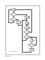
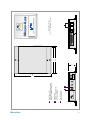
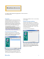
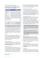
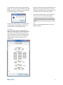
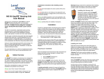
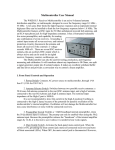
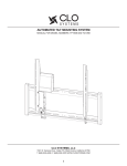
M icro ‑A ide
www.micro-aide.com
Low Power Modems
Highway Products
Limited Distance Modems
Failed LED Detectors
Light Out Detectors
Load Switches
Local Control Units
Custom Engineering
LPM
Low Power Modem
User Manual
Micro‑Aide Corporation
Tel: 626‑915‑5502
Fax: 626‑331‑9484
685 Arrow Grand Circle      Covina, CA   91722
E‑mail: [email protected]
LPM
L ow P ower M odem
U ser M anual
Commercially available modems are generally not suitable for use
in highway applications. However, the LPM operates over a temperature range extending from –40°C to +72°C. Its low power design
allows it to be powered by a small solar panel.
Introduction
This document provides a detailed description of the
use and operation of the MICRO‑AIDE Low Power
Modem (LPM). It also provides a detailed description
of the installation and use of MICRO‑AIDE’s Modem‑
Config Application. The latter is used to create and
save the profile used by the LPM.
Description
The LPM is specifically designed for use in highway
applications requiring remote access via standard
telephone lines. It will operate in severe temperature
conditions as typically found in roadside facilities. It
can be powered by any source in the range from 5 to
36 Vdc. It also features a low power Standby Mode. A
front-panel-accessible switch allows the user to select
the power mode. A battery charged by a solar panel
provides an excellent method of powering the LPM
when Standby Mode is enabled.
standard error correction and data compression al‑
gorithms are also supported. The LPM will operate in
auto-answer and originate modes.
The LPM is housed in a rugged aluminum case. It
will operate over temperature ranges associated with
highway equipment. Front panel LEDs indicate the
status of the modem at all times.
A standard DB‑25 connector allows the LPM to be
connected to a wide array of highway data equipment.
Typical applications include remote access to vehicle
detectors and weigh-in-motion systems.
The LPM is designed to meet all of the requirements
for a modem device intended for use with a Peek
ADR®.
Figure 2 on page 6 provides a three-sided,
dimensioned view of the LPM. More detailed informa‑
tion is included in the section entitled “Specifications”
on page 7.
With Standby Mode enabled, several timers are em‑
ployed by the LPM. The timers are used to reduce net
Installation
power consumption. Sixty seconds after the termina‑
The LPM is housed in a case that includes mounting
tion of ringing voltage or 120 seconds after the cessa‑
ears at either side. The diameter of each hole is .219".
tion of DTE data, the LPM will automatically revert to
The mounting holes are 6.134"
low power operation. Low power
apart. The modem can be se‑
operation will also be invoked
N ew LPM
cured to any flat surface including
10 seconds after the loss of car‑
MICRO‑AIDE designed its first LPM in
a backboard.
rier. The mode control sequence
1995. In 2012 the LPM was once again
employed by the LPM is illustrated
redesigned. The latest design includes
A standard 25‑pin, RS‑232 cable
in Figure 1 on page 5.
all of the capabilities of the earlier vercan be used to connect the LPM
sions, but is now housed in a substanto the DTE device. The LPM is
Baud rates up to 33,600 are sup‑
tially smaller package.
equipped with a female connec‑
ported by the LPM. Its high speed
tor configured for DCE operation.
makes the LPM ideally suited to
The new LPM design uses a Silicon
The specifications page lists each
applications where large amounts
Labs chip. The new chip introduces a
of the RS‑232 signals provided by
of data are transferred. Industry
slightly different set of AT commands.
the LPM.
M icro ‑A ide
2
The telephone line is attached to the LPM via a
standard RJ‑11 connector. Dual jacks are available at
the rear panel of the LPM. A utility phone can be used
while the modem is inactive.
&D2: line hangs up with drop of DTR
\Q0: disable flow control
S7=90: wait 90 seconds for carrier before hanging up
S0=1: modem answers in two rings
A 6' long power cable is shipped with every LPM. The
cable is terminated with a standard 3.5 mm plug. The
plug mates with the power jack also located at the
rear panel of the LPM. The red wire of the cable at‑
taches to the center pin of the jack and must be con‑
nected to the positive terminal of the power source.
The black wire must be connected to the negative
terminal of the power source.
A complete list of AT commands used by the LPM is
available from MICRO‑AIDE.
Alternatively, the LPM can be powered by a nominal
12 Vac source. A Stancor STA‑4112A wall mount
transformer can be used for this purpose. It connects
directly to any 120 Vac outlet. The transformer has a
rated output of 12 Vac at 500 mA. Its output cable is
terminated with a 3.5 mm plug.
Contact MICRO AIDE if the Stancor wall mount
transformer is required.
Setup
The LPM includes support for a single operating
profile. In some applications the factory-installed
profile may need to be modified. Modem profiles are
largely determined by the operational aspects of the
DTE attached to the LPM and the call originating
system. The LPM supports many industry standard
AT and Hayes commands. However, several modem
characteristics are not uniformly coded by modem
manufacturers.
MICRO‑AIDE’s ModemConfig App must be used
to create a new LPM profile. The latter half of this
User Manual provides a complete description of the
ModemConfig App.
Unless otherwise requested, each LPM is pro‑
grammed prior to shipment by the following initial‑
ization string. This string will support applications
involving the Peek ADR. A separate command, rather
complex and therefore not listed, is used to save the
profile.
ATE0X0&D2\Q0S7=90S0=1
The six AT commands listed above allow the LPM to
operate as follows:
E0: disable echoing of commands to DTE port
X0: disable extended result codes to DTE port
M icro ‑A ide
The LPM operation controlled by the preceding com‑
mands may be appropriate for the user’s intended
application. If not, the profile will need to be changed.
The modem is ready for use after the correct profile is
programmed and saved into the non-volatile memory
of the LPM.
Operation
To operate the LPM start by making the necessary
power, phone line and DTE cable connections.
Except as noted below, after power is applied to the
LPM the green LED labeled “Stby” will start flashing
immediately. This indicates that Standby Mode is
enabled and that the modem is in a low power state.
The modem is in Active Mode whenever the standby
LED is off. The LED will turn off when the DTE sends
data or ringing voltage is detected.
The Standby Mode of the LPM can be disabled. This
option may be useful in applications where the
modem is not being powered by a solar panel.
Disabling the Standby Mode of the LPM forces the
modem into continuous Active Mode. To disable
Standby Mode, locate the DIP switch at the front
panel of the modem. Throw the right-hand switch to
its lower position. The front panel silkscreening can be
used as a guide. The standby LED will remain off with
power applied to the modem.
For low power applications, the right-hand DIP
switch must always be placed in its upper position.
The left-hand DIP switch is never used.
The LEDs will illuminate in accordance with the follow‑
ing descriptions.
Stby: flashes while modem is in low power state, off
while modem is active
RI: flashes when ringing voltage is present
RD: data received from the phone line
SD: data from the DTE and sent by the modem
OH: modem is off hook
CD: carrier from the far end modem has been de‑
tected
3
The current profile used by the LPM can be reviewed
at any time. To do so, connect the communica‑
tions port of a PC directly to the DB‑25 connec‑
tor of the LPM. A communications program (e.g.,
HyperTerminal® or Procomm®) can be used to access
the LPM. Use the following AT command sequence to
report the profile settings.
AT$S$&$%$\$
The results will be grouped into five categories.
Additionally, the ModemConfig App can be used
to review the current profile. Refer to the section
entitled “View Profile” on page 10 for additional
details.
Maintenance and Trouble-Shooting
The LPM is designed to be completely maintenance
free. It contains no consumable materials or service‑
able components. If the unit fails to power-up (as
indicated by the Stby LED not flashing) the unit should
be returned to MICRO‑AIDE for repair.
The operation of the LPM can be easily tested. Any
PC equipped with a modem and a communications
program can be used to access the LPM. A check of
the modem’s ability to answer, connect and communi‑
cate can be performed very effectively. Remote tests
of the LPM can be made by MICRO‑AIDE technicians
at the request of the user.
MICRO‑AIDE provides a limited three-year warranty
for the LPM. Contact information is listed below.
M icro ‑A ide C orporation
685 Arrow Grand Circle
Covina, CA 91722
Tel: 626‑915‑5502
Fax: 626‑331‑9484
E‑mail: [email protected]
M icro ‑A ide
4
Standby
Mode
Ring in?
Y
N
DTE data?
N
Set TO to
60 sec
Y
Set TO to
120 sec
Active
Mode
Decr TO
1 sec
TO is 0 sec?
Y
N
Carrier on?
Y
N
Call in
progress
Carrier on?
Y
N
Set TO to
10 sec
TO refers to Time Out value
Figure 1: Mode Control Flow Diagram
M icro ‑A ide
5
Figure 2: Three‑Sided Dimensional View
M icro ‑A ide
6
M ICRO -A IDE Active
Low Pwr
Wired in parallel
C Dual phone jacks:
1 2
ON
A
Stby
RI
B
Flashes in Standby Mode
Off in Active Mode
B Standby LED:
SD
RD
Up for low power Standby Mode
Down for Active Mode always on
A Right-hand switch:
CD
OH
Low Power
Modem
6.6"
1.3"
4.8"
4.7"
To DTE
5-36Vdc
12Vac
Phone
Line
C
Mounting Holes (2)
Dia: .219" Spacing: 6.134" apart
LOW POWER MODEM
LPM
M ICRO -A IDE
LPM
L ow P ower M odem
S pecifications
Physical
Size
Length: 6.6"
Width: 4.8"
Height: 1.3"
Weight: 10 oz.
Environmental
Storage
Temperature: -50°C to +85°C
Humidity: 0% to 95%, non-condensing
Operating
Temperature: -40°C to +72°C
Humidity: 0% to 95%, non-condensing
Mounting
Shelf or desktop
Construction
Chassis
Fully enclosed, anodized aluminum,
externally accessible connectors, LEDs and
switches
Electrical
Single PCB with conformal coating, mounted
inside chassis
Power
Voltage
DC: 5 to 36
AC: 10 to 15 (optional AC power adapter
available)
Consumption
Standby Mode: maximum .5 mA at 12 Vdc
Active Mode: typical 85 mA at 12 Vdc
Operation
Standby Mode
Low power while awaiting ringing or DTE
data
Standby to Active Transition Delays
Within 6 sec of ringing or 200 msec of DTE
data
Answer
After transition to Active Mode, answers call
in accordance with S0 register setting
Disconnect
Loss of carrier, DTR drop or on hook com‑
mand
Active to Standby Transition Delays
Active Connection: 10 sec after loss of
carrier
No Connection: 60 sec after last ring or
120 sec after last DTE data
Controls
Externally accessible, DIP switch enables or
disables Standby Mode
Connectors
Power
Standard 3.5 mm jack, center positive
DTE
Type: DB‑25, female , configured as DCE
Signals: RD, SD, CTS, RTS, DSR, DTR,
DCD, RI, Signal Ground
Phone
Dual RJ‑11, wired in parallel
LED Indicators
Green: flashes while in Standby Mode, off
while in Active Mode
Red: Qty. 5, Receive Data, Transmit Data,
Off Hook, Ring In, Carrier Detect
M icro ‑A ide
DTE Interface
Configured as DCE
Auto-Baud detection (fixed Baud rate avail‑
able)
Line Protection
Internal MOV device used across tip and
ring
A telco approved external suppressor should
be used for added protection
Regulatory
Designed to meet applicable FCC standards
Modem Standards
Speed: 300 to 33.6K Baud, V.21, V.22, V.29
Fast Connect
Data Compression: V.42bis, V.44
Error Correction: V.42, MNP 2‑5
Control Commands
AT command compatibility
Supports most standard Hayes commands
Includes additional AT commands for control
of other modem features
Profile
Support for one profile
Defined by the sequence of various AT
commands
Active profile is volatile until saved to
EEPROM
Use MICRO‑AIDE’s ModemConfig App to
create and save the profile
MICRO‑AIDE reserves the right to make
changes, at its sole discretion, to any specification listed herein.
7
M odem C onfig A pplication
Use MICRO‑AIDE’s ModemConfig Application to create and save a
new modem profile.
Description
The ModemConfig App is used to create and save a
new modem profile. It can be installed and run on any
Windows XP®, Windows Vista® or Windows 7® PC.
The application requires that specific library files be
installed on the PC. Accordingly, a second executable
file must also be installed. Both installation proce‑
dures are described in the following two sections.
The modemconfig_v101.exe and
qt4_runtime_v470.exe files can be downloaded
without charge from MICRO‑AIDE’s website. Visit:
www.micro-aide.com/support/downloads.htm
Runtime library installation. Version 4.7.0 of the library
is now available.
ModemConfig App Installation
Download, unzip and then save to an appropriate
location the setup_modemconfig_v101.exe file. Once
saved, double-click the .exe file to initiate the installa‑
tion process. Continue with the standard installation
by clicking the button labeled “Next >” in each of five
successive dialog boxes.
The following screen will be displayed.
QT Runtime Library Installation
Download, unzip and then save to an appropriate
location the qt4runtime.exe file. Once saved, doubleclick the .exe file to initiate the installation process.
The following screen will be displayed.
Click the button labeled “Finish”. Complete the instal‑
lation by clicking the button labeled “OK” in the final
dialog box. Version 1.01 of the ModemConfig App is
ready for use. An icon labeled “ModemConfig” will be
displayed on the PC’s desktop.
Continue with the standard installation by clicking
the button labeled “Next >” in each of five successive
dialog boxes. Click the buttons labeled “Finish” and
“OK” in the final two dialog boxes to complete the QT4
M icro ‑A ide
8
Create a New Modem Profile
To create a new profile, start by double-clicking the
ModemConfig icon on the PC’s desktop. A screen
similar to the following will be displayed.
initial setting displayed by ModemConfig. Selecting
a Baud rate is not required provided the LPM’s DTE
port is set to auto-Baud (\T16 setting).
Select Common AT Settings
The most common settings used to create a new
profile are listed in the upper section of the dialog
box. Five drop-down list boxes allow the user to easily
select a variety of important settings. Select the “---”
entry to ignore a particular setting. These settings will
be sent to the LPM in top-to-bottom order.
Additional AT Settings
To assign additional profile settings, click in the area
labeled “Other AT Commands:”. This area serves as
a large text-edit box. It can be used to create a
sequence of additional commands that are user
specific. An AT-prefix is not required. The command
string that is formed by the individual commands will
be sent after the common settings. A space character
is not required to delimit each command.
Initially the ModemConfig App displays a single dialog
box. The dialog box shown above is used primarily to
assign specific profile settings. A second dialog box is
used to report the profile settings currently in use. Re‑
fer to the section entitled “View Profile” on page 10
for additional details. A description of each component
included in the dialog box is provided in the following
sections.
Help
The ModemConfig App includes two commands at
the top of the dialog box. The Help command can be
found there. Click the command to launch the PC’s
default browser. A Help file in the form of an html
page can then be read.
Select a Comm Port
Click the drop-down list box labeled “Port”. Select an
appropriate port from the list (e.g., “COM5” as shown
in the above). ModemConfig will use this port to com‑
municate with the LPM.
Select a Baud Rate
Click the drop-down list box labeled “Baud:”. Select
the Baud rate that matches the rate presently used by
the LPM. For example, if the LPM is currently using
a fixed Baud rate of 19,200, then the “19200” setting
must be selected. The “38400” setting is always the
M icro ‑A ide
Care should be exercised when assigning additional
commands. The ModemConfig App is not able to
report an error in any command string. For example,
the command %XY will fail, but not be reported as
an error.
Additionally, the following fixed Baud rate commands must not be used: \T5, \T7, \T13, \T14 and
\T15. These settings will result in fixed Baud rates
that are not supported by HyperTerminal and/or the
ModemConfig App.
Save the Profile
The command labeled “File” includes the standard
Windows “Save” and “Save As” sub-commands.
They can be used to save the currently listed settings
as a .txt file. The resultant file can be saved at any
location. As a .txt file, it can be viewed by a variety of
commonly available applications.
Open a Saved Profile
The “File” command also includes the “Open” subcommand. It can be used to quickly load the Modem‑
Config dialog box with the contents of a previously
saved profile.
Send Profile
The final step is to send the new profile to the LPM.
Before doing so, carefully review each setting. Make
sure the appropriate PC port and LPM are connected
9
via a suitable cable. Click the button labeled “Send to
Modem”. The send and receive data LEDs of the LPM
will flash briefly. At the completion of the transmission
the following dialog box will be displayed.
The View Profile feature will report data similar to that
depicted in the previous sample screen. If required,
enlarge the vertical dimension of the dialog box or use
the vertical scroll bar to view all of the settings.
Click the button labeled “OK” to close the dialog box
and return the focus to the ModemConfig App.
The settings shown in the previous screen reflect
Peek’s recommended profile for use with their ADR
devices.
Click the button labeled “OK” to return to the Modem‑
Config dialog box. The LPM will now operate in ac‑
cordance with the newly established profile.
Exit
Click the command labeled “File>Exit” to close the
ModemConfig App.
View Profile
The profile currently saved in the EEPROM of the
LPM can be easily inspected. Click the button labeled
“View Profile”. A new dialog box will be opened. Its
contents will display the values of 42 different profile
settings. This feature can be used to verify that the
LPM will operate in accordance with the user’s
requirements.
M icro ‑A ide
10