1
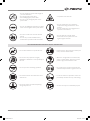
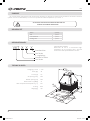
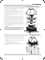
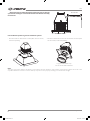
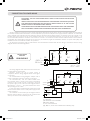
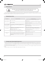
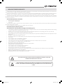
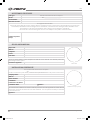
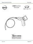
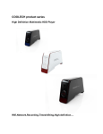
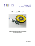
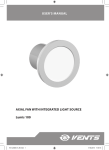
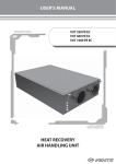
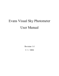
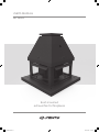
USER’S MANUAL
VKT Series
Roof-mounted
exhaust fan for fireplaces
V105EN-02.indd 1
03.09.2015 14:13:22
VKT
CONTENT
Safety requirements ................................................................................................
Purpose ......................................................................................................................
Delivery set ................................................................................................................
Designation key ........................................................................................................
Technical data ...........................................................................................................
Design and operating logic ....................................................................................
Mounting and set-up ..............................................................................................
Connection to power mains ..................................................................................
Maintenance .............................................................................................................
Troubleshooting .......................................................................................................
Storage and transportation regulations .............................................................
Manufacturer's warranty ........................................................................................
Acceptance certificate ............................................................................................
Seller information ....................................................................................................
Installation certificate ..............................................................................................
Warranty card ...........................................................................................................
2
4
4
4
5
6
8
8
9
9
9
10
11
11
11
11
The user’s manual consisting of the technical details, operating instructions and technical specification applies to the installation
and mounting of the roof-mounted chimney exhaust fan VKT, (hereinafter « the the fan» or «the unit» as mentioned in the «Safety
Requirements» and «Manufacturer’s Warranty» sections as well as in warnings and information blocks).
SAFETY REQUIREMENTS
Read the user’s manual carefully prior to installing and operating the unit.
Fulfil the user’s manual requirements as well as the provisions of all the applicable local and national construction, electrical and
technical norms and standards.
The warnings contained in the user’s manual must be considered most seriously since they contain vital personal safety information.
Failure to follow the rules and safety precautions noted in this user’s manual may result in an injury or unit damage.
After a careful reading of the manual, keep it for the entire service life of the unit.
While transferring the unit control the User’s manual must be turned over to the receiving operator.
Symbol legend:
WARNING!
DO NOT!
UNIT MOUNTING AND OPERATION SAFETY PRECAUTIONS
• Disconnect the unit from power mains
prior to any installation operations.
• Do not lay the power cable of the unit in
close proximity to heating equipment.
2
V105EN-02.indd 2
• The unit must be grounded!
•
While installing the unit follow the
safety regulations specific to the use of
electric tools.
www.ventilation-system.com
03.09.2015 14:13:22
• Do not change the power cable length at
your own discretion.
• Do not bend the power cable.
• Avoid damaging the power cable.
• Do not put any foreign objects on the
power cable.
• Unpack the unit with care.
• Do not use damaged equipment or cables
when connecting the unit to power mains.
• Do not operate the unit outside the
temperature range stated in the user’s
manual.
• Do not operate the unit in aggressive or
explosive environments.
• Do not touch the unit controls with wet
hands.
• Do not carry out the installation and
maintenance operations with wet hands.
• Do not wash the unit with water.
• Protect the electric parts of the unit
against ingress of water.
UNIT MOUNTING AND OPERATION SAFETY PRECAUTIONS
• Do not allow children to operate the unit.
• Disconnect the unit from power mains prior
to any technical maintenance.
• Do not store any explosive or highly
flammable substances in close proximity to
the unit.
• When the unit generates unusual sounds,
odour or emits smoke disconnect it from
power supply and contact the Seller.
• Do not open the unit during operation.
• Do not direct the air flow produced by the
unit towards open flame or ignition sources.
• Do not block the air duct when the unit is
switched on.
• In case of continuous operation of the unit
periodically check the security of mounting.
• Do not sit on the unit and avoid placing
foreign objects on it.
• Use the unit only for its intended purpose.
www.ventilation-system.com
V105EN-02.indd 3
3
03.09.2015 14:13:24
VKT
PURPOSE
The roof-mounted centrifugal fan with horizontal air discharge is designed for both general ventilation and smoke extraction
systems. The fan can withstand up to 5 hours of operation at smoke temperatures up to +200 ˚C.
ATTENTION! THE FAN MUST ALWAYS BE SWITCHED ON
DURING THE CHIMNEY OPERATION!
DELIVERY SET
Name
Quantity
Fan
1 piece
User's Manual
1 piece
Package box
1 piece
DESIGNATION KEY
VKT X X X
Standard size
Fan designation example:
VENTS VKT 4E 250 is a roof-mounted hightemperature fan for fireplaces with a four-pole
electric motor and impeller diameter 250 mm.
Fan Series
E - single-phase
Number of Poles
Fan Series
TECHNICAL DATA
323
1~230
Power, [W]
96
Current, [A]
0,6
Air capacity, [m3/h]
1000
Rotation speed, [rpm]
1500
Noise level at 3 m, [dB(A)]
52
Max. transported air temperature, [˚C]
200
IP rating
IP44
Weight, [kg]
14,6
434
Voltage, [V] / 50 Hz
Ø11
430
330
Ø250
4
V105EN-02.indd 4
www.ventilation-system.com
03.09.2015 14:13:24
DESIGN AND OPERATING LOGIC
The fan casing is made of galvanized polymer coated and weather
resistant steel. The fan has a protective grille to prevent accidental
touching and penetration of foreign objects.
The metal frame is treated with a heat-resistant polymer coating for
an extended service life and weather protection.
The fan is equipped with a 96 W single-phase asynchronous electric
motor designed for 230 V / 50 Hz supply mains voltage. The fan has
thermal insulation for high-temperature environments while the roller
bearings ensure a long and trouble-free operation.
A specially designed impeller minimizes soot and carbon deposits
for smooth operation.
The electric motor drives an impeller with backward-curved
blades. The motor is offset from the handled air stream. The motor
compartment is isolated from the air stream with an air cushion created
between the deflecting plate and the deck. Any precipitation or dust
which may penetrate from the top of the motor is blocked off by the
protective housing with a sealed electric lead-in. The electric lead-in is
not included in the delivery set and must be purchased separately. The
electric lead-in must withstand the temperature up to +200 °C.
The housing ventilation openings ensure proper air circulation and
removal of heat generated by the motor. The ventilation openings are
arranged in such a way so as to prevent penetration of rainwater inside.
The air is discharged horizontally through the service openings in
the air grilles attached to the base. The air grille bars provide extra
protection against precipitation.
WARNING!
The fan must be operated with the maximum speed at
the transported air temperature exceeding +200 °C. At this
temperature conditions the use of a speed controller is forbidden
for fire safety reasons and for overheating prevention.
Housing
Motor
Platform
Deflecting plate
Sleeve
Impeller
Base
MOUNTING AND SET-UP
• Unpack the fan and check for any cuts in the electric wires and
cracks in the insulation. Inspect the fan casing to make sure it is free
from any cracks and deformations. Set the impeller in motion and
check that it rotates freely without catching against the inlet flange
and the casing.
• Prior to power mains connection make sure that the power mains
parameters comply with the technical data on the fan sticker
attached to the protective housing.
Fan installation on the chimney brick masonry:
Install the fan onto the chimney brick masonry and fix it through the
holes in the fan base.
www.ventilation-system.com
V105EN-02.indd 5
5
03.09.2015 14:13:24
VKT
Warning! Route the cable though the spiral wrap hose or through
a protective metal pipe. It must be located at least 500-700 mm away
from the fan.
500-700 mm
Fan installation options in general ventilation systems:
• Roof-mounted fan attachment to frame (RKV 250-310 model,
ordered separately).
• Round duct attachment to the fan via a flexible connector (GKV
250-315 model, ordered separately).
For general ventilation only!
Do not use for smoke extraction!
Note:
The upper part of the chimney may differ in size from the fan base. However, if the chimney cross-section is below 15x15 cm or the
equivalent diameter is below 17 cm the chimney may not function properly resulting in an insufficient draught.
6
V105EN-02.indd 6
www.ventilation-system.com
03.09.2015 14:13:25
CONNECTION TO POWER MAINS
DISCONNECT THE UNIT FROM POWER SUPPLY PRIOR TO ANY ELECTRIC INSTALLATION
OPERATIONS.
INSTALLATION SHALL ONLY BE PERFORMED BY A PROFESSIONAL ELECTRICIAN QUALIFIED
FOR UNASSISTED OPERATIONS WITH ELECTRICAL INSTALLATIONS UP TO 1000 V AFTER
CAREFUL STUDY OF THE PRESENT USER’S MANUAL.
THE RATED ELECTRICAL PARAMETERS ARE STATED ON THE RATING PLATE. ANY TAMPERING
WITH THE INTERNAL CONNECTIONS IS PROHIBITED AND WILL VOID THE WARRANTY.
The fan is rated for connection to 230 V/ 50 Hz single-phase alternating current mains. The fan connections (cables and wires) must
be durable, insulated and heat-resistant. The external power input (230 V / 50 Hz) must be equipped with an automatic circuit breaker
with a magnatic trip integrated into the stationary wiring to disconnect all the mains phases. The location of the QF external circuit
breaker must ensure free access for quick shutdown of the fan. The recommended rated trip current of the circuit breaker is 1 A,
the recommended minimum conductor cross-section is 0.75 mm2. The conductor section selection shall be based on the maximum
permissible wire heating which depends on the wire type, its insulation, length and installation method. The power lead quality and
installation must ensure failsafe durable fan operation.
The electrical connections must be terminated on the terminal block located inside the fan casing in accordance with the wiring
diagram and the terminal designations.
C
ENSURE PROPER
AND SAFE
GROUNDING!
L
QF
W2
U2
V2
U1
V1
W1
X1
~230V
50 Hz N
W2, U1 — red
U2, V1 — black
The wiring diagrams and rotation direction stickers are
located inside the terminal box.
Attention! Connect the fan to power supply in
compliance with the wiring diagram shown on the figure
on the right.
The recommended wiring diagram example with a
motor overheating protection is shown on the figure.
The terminals TW1, TW2 are leaded outside from
the normally closed contact of the motor overheating
protection. This contact must be connected in series to
the power supply circuit of the coil of the magnetic starter
KM (Upower = 230 V, I = 10 A) that activates the motor
after pressing the S1 button.
In case of the motor overheating the contact opens and
disconnects the starter coil to cut off power supply tot the
motor and stop it.
The automatic circuit breaker QF, the magnetic starter
KM, the control buttons S1 and S2 are not included in the
delivery set and must be installed by the user.
C
L
QF
KM
W2
U2
V2
U1
V1
W1
~230V
50 Hz N
S1
Start
KM
X1
T˚
TW1
TW2
S2
Stop
X1: fan terminal block
C1: capacitor
QF: automatic circuit breaker
KM: motor starter
S1, S2: control buttons
(QF, KM, S1, S2 are not included in the delivery set)
www.ventilation-system.com
V105EN-02.indd 7
7
03.09.2015 14:13:25
VKT
MAINTENANCE
DISCONNECT THE UNIT FROM POWER SUPPLY BY PULLING THE PLUG OUT OF THE
SOCKET PRIOR TO ANY ELECTRIC INSTALLATION OPERATIONS.
Maintenance means regular cleaning of the unit surfaces of dust. To remove dust use a soft brush, cloth or a vacuum cleaner. Do
not use water, abrasive detergents, solvents, sharp objects. Clean the impeller blades every 6 months. To clean the impeller use a warm
detergent solution, but make sure to keep the water off the electric motor.
TROUBLESHOOTING
Problem
The fan does not
start on power-up.
The circuit breaker
activates upon the
unit power-up.
Low air flow.
Excessive noise or
vibration.
Possible reasons
Troubleshooting
No electric power.
Check the electrical connections and the power
switch status.
Motor jamming.
Turn the fan off. Troubleshoot the impeller clogging.
Switch the fan back on.
The automatic circuit breaker is triggered by an
abnormally high current consumption due to a short
circuit.
Disconnect the fan from the power mains and contact
the service centre.
Do not switch off the fan until the malfunction has
been troubeshooted!
Clogging of air ducts or other ventilation system
elements due to contamination.
Impeller contamination.
Damaged air ducts. Closed air dampers.
Clean the air ducts and other ventilation system
elements as well as the impeller. Check the air ducts
for damage. Make sure that the air dampers and
louvre shutters are open.
Loose threaded joints, contaminated impeller.
Clean the fans.
Tighten any loose threaded joints.
Worn out bearings, foreign objects in the impeller.
Contact the service centre.
Unstable electric power supply or electric motor
malfunction.
Contact the service centre.
STORAGE AND TRANSPORTATION RULES
Store the unit in the manufacturer’s original packing box in a dry ventilated premise at ambient temperatures from +5 °C up to +40 °C.
Storage environment must not contain aggressive vapours and chemical mixtures provoking corrosion, insulation and sealing deformation.
Use suitable hoist machinery for handling and storage operations to prevent possible damage to the unit. Follow the handling requirements
applicable for the particular type of cargo.
The unit can be carried in the original packing by any mode of transport provided proper protection against precipitation and mechanical
damage.
Avoid sharp blows, scratches or rough handling during loading and unloading.
8
V105EN-02.indd 8
www.ventilation-system.com
03.09.2015 14:13:25
MANUFACTURER’S WARRANTY
The manufacturer hereby warrants normal operation of the unit for 24 months after the retail sale date provided the user’s observance
of the transportation, storage, mounting and operation regulations.
Should any malfunctions occur in the course of the unit operation through the Manufacturer’s fault during the guaranteed period of
operation the user is entitled to elimination of faults by the manufacturer by means of warranty repair at the factory free of charge.
The warranty repair shall include work specific to elimination of faults in the unit operation to ensure its intended use by the user within
the guaranteed period of operation. The faults are eliminated by means of replacement or repair of the unit components or a specific part
of such unit component.
The warranty repair does not include:
•
Routine technical maintenance;
•
Unit installation / dismantling;
•
Unit setup.
To benefit from warranty repair the user must provide the unit, the user’s manual with the purchase date stamp and the payment
document certifying the purchase.
The unit model must comply with the one stated in the user’s manual.
Contact the Seller for warranty service.
The manufacturer’s warranty does not apply to the following cases:
•
User’s failure to submit the unit with the entire delivery package as stated in the user’s manual including submission with missing
component parts previously dismounted by the user.
•
Mismatch of the unit model and the brand name with the information stated on the unit packing and in the user’s manual.
•
User’s failure to ensure timely technical maintenance of the unit.
•
External damage to the unit casing (excluding external modifications as required for installation) and internal components caused
by the user.
•
Redesign or engineering changes to the unit.
•
Replacement and use of any assemblies, parts and components not approved by the manufacturer.
•
Unit misuse.
•
User’s violation of the unit installation regulations.
•
User’s violation of the unit control regulations.
•
Unit connection to the power mains with a voltage different from the one stated in the user’s manual.
•
Unit breakdown due to voltage surges in the power mains.
•
Discretionary repair of the unit by the user.
•
Unit repair by any persons without the manufacturer’s authorization.
•
Expiration of the unit warranty period.
•
User’s violation of the unit transportation regulations.
•
User’s violation of the unit storage regulations.
•
Wrongful actions against the unit committed by third parties.
•
Unit breakdown due to circumstances of insuperable force (fire, flood, earthquake, war, hostilities of any kind, blockades).
•
Missing seals if provided by the user’s manual.
•
Failure to submit the user’s manual with the unit purchase date stamp.
•
Missing payment document certifying the unit purchase.
FOLLOWING THE REGULATIONS STIPULATED HEREIN WILL ENSURE A LONG AND
TROUBLE-FREE OPERATION OF THE UNIT.
USERS’ WARRANTY CLAIMS SHALL BE SUBJECT TO REVIEW ONLY UPON PRESENTATION OF
THE UNIT, THE PAYMENT DOCUMENT AND THE USER’S MANUAL WITH THE PURCHASE DATE
STAMP.
www.ventilation-system.com
V105EN-02.indd 9
9
03.09.2015 14:13:25
VKT
ACCEPTANCE CERTIFICATE
Unit Type
Model
Roof-mounted exhaust fan for fireplaces
VKT ________________________________
Serial Number
Manufacture Date
Is recognized as serviceable.
We hereby declare that the product complies with the essential protection requirements of Electromagnetic Council Directive
2004/108/EC, 89/336/EEC and Low Voltage Directive 2006/95/EC, 73/23/EEC and CE-marking Directive 93/68/EEC on the
approximation of the laws of the Member States relating to electromagnetic compatibility.
This certificate is issued following test carried out on samples of the product referred to above.
Quality Inspector’s
Stamp
SELLER INFORMATION
Shop name
Address
Telephone
E-mail
Sales date
This is to certify delivery of the complete fan with the user's manual. The warranty terms are
acknowledged and accepted.
Customer’s signature
Seller’s seal
INSTALLATION CERTIFICATE
The roof-mounted exhaust fan for fireplaces
VKT ________________________________
has been connected to power mains pursuant to the requirements stated in the present user’s manual.
Company Name
Address
Phone Number
Installation
Technician's Full Name
Installation Date:
Signature:
The unit has been installed in accordance with the provisions of all the applicable local and national
construction, electrical and technical codes and standards. The unit operates normally as intended
by the manufacturer.
Installation Company Stamp
Signature:
10
V105EN-02.indd 10
www.ventilation-system.com
03.09.2015 14:13:25
WARRANTY CARD
Unit Type
Model
Roof-mounted exhaust fan for fireplaces
VKT ________________________________
Serial Number
Manufacture Date
Purchase Date
Warranty Period
Seller
Seller’s Stamp
www.ventilation-system.com
V105EN-02.indd 11
11
03.09.2015 14:13:25
V105EN-02
V105EN-02.indd 12
03.09.2015 14:13:25