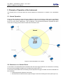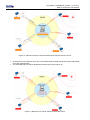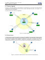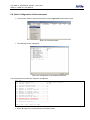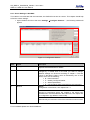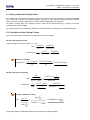
1
GMS-xx GSR-IAx User Manual GeoSIG Ltd, Ahornweg 5A, 5504 Othmarsingen, Switzerland Phone: + 41 44 810 2150, Fax: + 41 44 810 2350 [email protected], www.geosig.com GS_GMS-xx_UserManual_V08.doc / 19.01.2011 GMS-xx & GSR-IAx User Manual Page ii Document Revision Author Checked Approved Markus Epp Thomas Linder Dr. Oleg Razinkov Version 21.02. 2007 09.03. 2007 16.03. 2007 V0d 16.04. 2007 V0e 26.05. 2007 V0g 12.12.2007 V0h 19.02.2008 V0i 20.10.2008 V0k 27.10.2008 V1 11.03.2009 V2 06.08.2009 V3 14.10.2009 V4 01.05.2010 V5 18.10.2010 V6 08.11.2010 V7 17.01.2011 V8 Action First issue for review Given to USGS for info only. Second issue for internal review Updated after reviewing. Removed SR comments in style 4. Updated with HW V1. Updated to HW V2 Updated after new firmware Updated after new firmware Updated for latest firmware and hardware Change of Address Update to V3 Update of Table 7, LSB value examples Data Processor added Complete revision of the manual Minor corrections Corrections related to the new features of the FW version 0.71 Disclaimer GeoSIG Ltd reserves the right to change the information contained in this document without notice. While the information contained herein is assumed to be accurate, GeoSIG Ltd assumes no responsibility for any errors or omissions. Copyright Notice No part of this document may be reproduced without the prior written consent of GeoSIG Ltd. The software described in this document is furnished under a license and may only be used or copied in accordance with the terms of such a license. Trademark All brand and product names mentioned are trademarks or registered trademarks of their respective holders. All rights reserved. GeoSIG Ltd Switzerland GS_GMS-xx_UserManual_V08.doc / 19.01.2011 GMS-xx & GSR-IAx User Manual Page iii Table of Contents Applicability of This Manual ................................................................................................. 7 Warnings and Safety ........................................................................................................... 7 Symbols and Abbreviations ................................................................................................. 8 1. Introduction...................................................................................................................... 8 2. Incoming Inspection......................................................................................................... 9 2.1. Damage during shipment ........................................................................................................................9 2.2. Warranty..................................................................................................................................................9 2.2.1. Limitation of Warranty......................................................................................................................9 2.3. Storage (Instrument Shelf Life) ...............................................................................................................9 2.3.1. Main battery ...................................................................................................................................10 2.3.2. Backup battery...............................................................................................................................10 3. Description..................................................................................................................... 11 3.1. Housing .................................................................................................................................................11 3.1.1. Base plate ......................................................................................................................................11 3.2. Connectors ............................................................................................................................................12 3.2.1. Standard External Connectors.......................................................................................................12 3.2.2. Optional External Connectors........................................................................................................12 3.2.3. Connectivity Options......................................................................................................................13 3.2.4. Internal Connector .........................................................................................................................14 3.3. Visual Indicators....................................................................................................................................14 3.3.1. Detail Description...........................................................................................................................15 3.4. Internal Batteries ...................................................................................................................................17 3.4.1. Main Battery...................................................................................................................................17 3.4.2. Backup battery...............................................................................................................................18 3.5. Power supply.........................................................................................................................................18 3.6. Supplied and Optional Accessories ......................................................................................................19 3.6.1. Standard Supplied Accessories.....................................................................................................19 3.6.2. Optional Accessories .....................................................................................................................19 4. Installation ..................................................................................................................... 20 4.1. Site Selection ........................................................................................................................................20 4.1.1. Environmental Considerations.......................................................................................................20 4.1.2. Power Supply Considerations........................................................................................................20 4.1.3. Communication Considerations.....................................................................................................21 4.2. Installation .............................................................................................................................................21 4.2.1. Requirements for the Instrument Foundation ................................................................................21 4.2.2. Mounting the Instrument ................................................................................................................21 4.2.3. Orientation, Levelling and Calibration of the Sensor .....................................................................22 4.2.4. Supply Voltage Selection...............................................................................................................22 4.2.5. Installing other Components, Options, Accessories......................................................................22 4.3. First Start and Communication Setup ...................................................................................................22 Page iv GS_GMS-xx_UserManual_V08.doc / 19.01.2011 GMS-xx & GSR-IAx User Manual 5. Principle of Operation of the Instrument.........................................................................23 5.1. Normal Operation ................................................................................................................................. 23 5.2. Behaviour on a Seismic Event ............................................................................................................. 23 5.3. Firmware Upgrade................................................................................................................................ 25 5.4. Backup Server ...................................................................................................................................... 25 6. Quick Start Up................................................................................................................26 6.1. Preparation ........................................................................................................................................... 26 6.2. Set IP Address of the Instrument ......................................................................................................... 27 6.3. No Stations Configured at first Start Up ............................................................................................... 28 6.4. Adding New Stations… ........................................................................................................................ 28 6.5. Configuration of Data Server................................................................................................................ 29 6.6. Basic Configuration of the Instrument .................................................................................................. 31 7. Network Settings ............................................................................................................33 7.1. Set IP through GeoDAS ....................................................................................................................... 33 7.2. Set IP through the Bootloader .............................................................................................................. 33 7.3. Wireless Settings through GeoDAS ..................................................................................................... 34 7.4. Wireless Settings through the Bootloader ............................................................................................ 34 8. Detailed Configuration of the Instrument........................................................................37 8.1. General Comments .............................................................................................................................. 37 8.1.1. Changing Configuration by the Terminal ...................................................................................... 37 8.1.2. Change Configuration by GeoDAS ............................................................................................... 37 8.1.3. Explanation of the Structure in the Manual................................................................................... 38 8.2. Switch ON and OFF the instrument ..................................................................................................... 39 8.3. Configuration of the Channels.............................................................................................................. 39 8.3.1. Calculation of the LSB factor ........................................................................................................ 41 8.4. Configuration of Data Streams ............................................................................................................. 43 8.4.1. Set up of Data Streams................................................................................................................. 45 8.5. Trigger Settings .................................................................................................................................... 47 8.5.1. STA/LTA trigger ............................................................................................................................ 49 8.5.2. Trigger Weight............................................................................................................................... 50 8.5.3. Trigger Time Frame ...................................................................................................................... 50 8.5.4. Trigger Interconnection over LAN ................................................................................................. 51 8.6. Preset Trigger Settings......................................................................................................................... 54 8.7. File Storage and Policy ........................................................................................................................ 56 8.8. Communication Parameters................................................................................................................. 58 8.8.1. Server Settings in GeoDAS .......................................................................................................... 61 8.8.2. PPP Link Configuration................................................................................................................. 63 8.9. Miscellaneous Parameters ................................................................................................................... 66 8.10. Auxiliary Devices ................................................................................................................................ 69 8.11. Other Options in the Instrument Main Menu ...................................................................................... 70 8.11.1. User requests.............................................................................................................................. 71 9. Open recorded miniSEED files in GeoDAS....................................................................73 9.1. Save predefined Scaling Factors ......................................................................................................... 74 9.2. Calculation of the Scaling Factors........................................................................................................ 74 GS_GMS-xx_UserManual_V08.doc / 19.01.2011 GMS-xx & GSR-IAx User Manual Page v 10. Instrument Control in GeoDAS .................................................................................... 76 10.1. More Information… (State of Health of the instrument) ......................................................................76 10.2. Instrument Setup… .............................................................................................................................77 10.3. Cancel Pending Request ....................................................................................................................77 10.4. GMS Communication Interface ...........................................................................................................77 11. Bootloader ................................................................................................................... 79 12. Firmware Upgrades ..................................................................................................... 80 13. Time synchronization................................................................................................... 82 13.1.1. Temperature compensation.........................................................................................................82 14. Telnet Access .............................................................................................................. 83 14.1. Telnet Client for Windows OS .............................................................................................................83 14.2. Telnet client for Linux OS....................................................................................................................84 15. Index............................................................................................................................ 85 List of Figures Figure 1, Instrument housing............................................................................................................................11 Figure 2, Instrument base plate........................................................................................................................11 Figure 3. Instrument with all connectors. Antennas are not mounted..............................................................12 Figure 4. Connectivity Options .........................................................................................................................13 Figure 5. Internal RS-232 connector for the console .......................................................................................14 Figure 6. Visual indicators on the cover (left) and inside the instrument (right) ...............................................14 Figure 7, RUN indicator ....................................................................................................................................15 Figure 8, EVENT indicator................................................................................................................................15 Figure 9, LINK indicator....................................................................................................................................16 Figure 10, ERROR indicator.............................................................................................................................16 Figure 11, File Checkup ...................................................................................................................................17 Figure 12. Installation of the base plate ...........................................................................................................22 Figure 13. Normal operation in a network ........................................................................................................23 Figure 14. Upload of seismic events and download of requests from the server ............................................24 Figure 15. Behaviour on Events: Upload of extracted events ..........................................................................24 Figure 16. Firmware upgrade ...........................................................................................................................25 Figure 17. Connection to backup server in case connection to main server fails ............................................25 Figure 18. GeoDAS terminal ............................................................................................................................26 Figure 19. No stations configured during start of GeoDAS ..............................................................................28 Figure 20. Instrument Wizard ...........................................................................................................................28 Figure 21. Quick Login Window .......................................................................................................................29 Figure 22. List of all stations found – single station left, multi-selection right side...........................................29 Figure 23. Configuration and overview of the stations .....................................................................................29 Figure 24. Data server parameter ....................................................................................................................30 Page vi GS_GMS-xx_UserManual_V08.doc / 19.01.2011 GMS-xx & GSR-IAx User Manual Figure 25. Instrument setup............................................................................................................................. 31 Figure 26. Configuration of the selected instrument........................................................................................ 31 Figure 27. Confirmation of uploading the new settings ................................................................................... 32 Figure 28. Station configuration....................................................................................................................... 33 Figure 29. Upload parameters to the instrument ............................................................................................. 33 Figure 30. WiFi Settings .................................................................................................................................. 34 Figure 31. Instrument setup............................................................................................................................. 37 Figure 32. Configuration window ..................................................................................................................... 38 Figure 33. Channels of Digitisers..................................................................................................................... 45 Figure 34. Stations: Data streams ................................................................................................................... 46 Figure 35. Data stream window ....................................................................................................................... 46 Figure 36. Overview of trigger weight and trigger time frame ......................................................................... 50 Figure 37. Configuration Stations .................................................................................................................... 61 Figure 38. Data server parameter.................................................................................................................... 62 Figure 39, GeoDAS miniSEED parameters..................................................................................................... 73 Figure 40, GeoDAS analyses parameters....................................................................................................... 73 Figure 41, Instrument control of the GMS in GeoDAS .................................................................................... 76 Figure 42. GMS Communication Interface ...................................................................................................... 77 Figure 43, Select GMS Control........................................................................................................................ 80 Figure 44, GMS Communication Interface ...................................................................................................... 80 Figure 45, Pending upgrade on the server ...................................................................................................... 81 Figure 46. Windows Run window .................................................................................................................... 83 Figure 47. Windows terminal emulator ............................................................................................................ 83 Figure 48. Linux terminal emulator .................................................................................................................. 84 Figure 49. Telnet Session................................................................................................................................ 84 GS_GMS-xx_UserManual_V08.doc / 19.01.2011 GMS-xx & GSR-IAx User Manual Page vii Applicability of This Manual GMS Instruments are constantly being improved. Although the manual you receive along with your instrument corresponds to the actual software versions, you are advised to check the GeoSIG web page periodically for the most recent version of this document, and especially after performing any software upgrades. This manual is based on the following software and firmware versions: Component Description Required version or higher GeoDAS Data Acquisition and Analysis Software on the computer 2.21 Newdas Data Acquisition software of the instrument 20.00.71 RTC Real time clock 80.00.19 DSP Signal processor 50.01.03 Bootloader Bootloader 1.19 uCLinux Operating System 0.26 Warnings and Safety STATIC ELECTRICITY The instrument and if available, its sensor unit contains CMOS devices and when serviced, care must be taken to prevent damage due to static electricity. This is very important to ensure long-term reliability of the unit. Such risk exists when both the instrument cover and the front panel are removed. INSIDE THE INSTRUMENT (MAINTENANCE) When it is desired to fully restrict the access to the unit so that even its cover cannot be removed, lockers can be mounted in the middle of the handles, on the side of the instrument. Under normal circumstances, there is no need to remove the front panel of the instrument. In any case, only trained person should remove the front panel. Moreover untrained access may lead to serious damage to the instrument, as well as may void the warranty. Before removing the front panel: 1. Turn the unit off 2. Disconnect all cables connected to the unit 3. Disconnect the battery 4. Make sure that all LED indicators are OFF BATTERY LIFE The instrument is shipped with an internal battery. Do not forget to connect the battery when you install the unit; the battery is provided with a polarised connector to avoid any wrong connections. In order to prevent data loss, you should be aware of the replacement policy of the battery before its expected lifetime expires. Battery expected life times under normal conditions is: Main battery Fiamm-FG29722, 12V 7.2Ah 3 years or similar type of battery The lifetime of the main battery can drastically change depending on operating conditions. Strong discharge of the main battery must be avoided. During normal operation, power comes from the external charger and charges the battery. The housing provides no protection against explosive atmosphere. It must not be directly operated in area where explosive gases could be present. GS_GMS-xx_UserManual_V08.doc / 19.01.2011 GMS-xx & GSR-IAx User Manual Page viii Symbols and Abbreviations ADC CF Bootloader Compact Flash ColdFire DSP Flash GPS LAN NTP PPS RAM RTC SPS SSH SSID STP UTP VPN WAN WPA WEP Analog to Digital Converter Compact Flash, memory card using Flash memory First program executed when unit starts See CF Main processor Digital Signal Processor in charge of controlling the ADCs Program storage memory device. It contains the Linux file system in Read Only mode and some block areas under direct control of main program or bootloader. Global Positioning System Local Area Network, a simple branch of private network using private IP address. It could have or not have access to Internet (WAN). Network Time Protocol Pulse Per Second Random Access Memory Real Time Clock Samples Per Second Secure Shell Service Set IDentifier, This is the identifier name of a wireless network. Shielded Twisted Pair Unshielded Twisted Pair Virtual Private Network Wide Area Network, it is a network connection established between 2 LAN or a LAN and a server over the internet (usual case) or through a rented link. WiFi Protected Access. It is a secure specification that allows users to access information instantly via wireless link. It is a more modern and secure link than the WEP type. Wired Equivalent Privacy 1. Introduction Dear Valued GeoSIG Customer, thank you for purchasing this product. These Instruments have been optimised to meet the requirements of the majority of customers out of the box and may have even been delivered tailored to your needs. In any case, to be able to get the most out of our product, please carefully study this manual, its appendices and referenced manuals, as well as any other documents delivered with it. This is a reliable and easy to use device, and at the same time a sophisticated product, which requires care, attention and know-how in configuring, installing, operating and maintenance. GeoSIG continuously improves and enhances capabilities of all products. There may be several other connectivity, hardware or software options for the instrument, which are not covered in this manual. Refer to separate documentation from GeoSIG about available options or ask GeoSIG directly. This document is made for use in direct connection with the instrument during installation, startup and servicing of the unit. GS_GMS-xx_UserManual_V08.doc / 19.01.2011 GMS-xx & GSR-IAx User Manual Page 9/85 2. Incoming Inspection All instruments are carefully inspected both electrically and mechanically before they leave the factory. Please check if all received items correspond with the packing list and your order confirmation. In case of discrepancy please contact GeoSIG or your local representative immediately. 2.1. Damage during shipment If requested at the time of order, all instruments can be insured prior to shipment. If you receive a damaged shipment and shipping insurance was previously arranged you should: • Report the damage to your shipper immediately • Inform GeoSIG or your local representative immediately • Keep all packaging and shipping documents a Insurance claims may be void if the above procedure is not followed. 2.2. Warranty GeoSIG Ltd (hereafter GeoSIG) warrants hardware and software products against defects in materials, workmanship and design for the defined period in the relevant contract or offer, starting from date of shipment and 5 years parts and maintenance support commitment. If GeoSIG receives notice of such defects during the warranty period, GeoSIG shall at its option either repair (at factory) or replace free of charge hardware and software products that prove to be defective. If GeoSIG is unable, within a reasonable time to repair or replace any cabinet to a condition as warranted, buyer shall be entitled to a refund of the purchase price upon return of the cabinet to GeoSIG. 50% of freight charges on shipments of warranty repairs or replacements will be borne by GeoSIG (normally one way freight). 2.2.1. Limitation of Warranty The foregoing guarantee shall not apply to defects resulting from: • • • • • • Improper or inadequate maintenance by buyer Buyer supplied software or interfacing Unauthorised modification or misuse Operation and storage outside of the environmental specifications of the instrument Related to consumables or batteries Improper preparation and installation at site. 2.3. Storage (Instrument Shelf Life) In case the instrument is stored, the batteries have to be maintained according to the storage duration. Period of time < 1 month 1–3 months 3–6 months External power supply Instrument is operating Main battery Real Time Clock backup battery ON YES Connected Connected ON NO Connected Connected OFF NO Connected Connected ON YES Connected Connected ON NO Connected Connected OFF NO Disconnected Connected ON YES Connected Connected ON NO Connected Disconnected OFF NO Disconnected Disconnected GS_GMS-xx_UserManual_V08.doc / 19.01.2011 GMS-xx & GSR-IAx User Manual Page 10/85 More than 6 months ON YES Connected Connected ON NO Connected Disconnected OFF NO Disconnected, must be recharged every 6 months for at least 24 hours. Disconnected Table 1, Storage instruction a Removing or replacing the backup battery must be done by a trained person only. Therefore if the instrument is stored for more than 3 month, always have it connected to power and let it running. 2.3.1. Main battery If the instrument is connected to AC power through its power supply module, the main battery can remain in the unit; it will remain charged and ready for use. Current leakage on main battery when unit is off, without external supply is about 40 μA. 2.3.2. Backup battery Autonomy of Real Time Clock on its backup battery is 3 years typical at ambient temperature. The jumper JMP401 on the main board has to be put in position 2-3 to disconnect this backup battery. This must be done by a trained person only. GS_GMS-xx_UserManual_V08.doc / 19.01.2011 GMS-xx & GSR-IAx User Manual Page 11/85 3. Description 3.1. Housing The instrument is a housing mounted with a base plate. The base plate is fixed on ground and levelled one time during installation, then the instrument can be replaced with no need for levelling. Figure 1, Instrument housing 1 3.1.1. Base plate A base plate is supplied with the instrument for fixation and levelling of instrument on site. 3 levelling feet are provided to adjust horizontally the base plate. The fixation is done as a single point in the middle of the plate. To insure correct orientation when an instrument is installed on the plate, 2 pins are provided with the plate. They can be mounted in different position, according to the orientation required and will fit in the 2 holes existing in the base of the instrument. A connection point for earthing is also provided with the plate as a M6 thread. Figure 2, Instrument base plate 1 Connectors may vary depending on ordered configuration GS_GMS-xx_UserManual_V08.doc / 19.01.2011 GMS-xx & GSR-IAx User Manual Page 12/85 3.2. Connectors The instrument has up to nine connectors and two antenna plugs: WiSync SENSOR 1 Wifi GPS SENSOR 2 SERIAL INTERCON LAN MODEM POWER ALARM Figure 3. Instrument with all connectors. Antennas are not mounted 2 3.2.1. Standard External Connectors These connectors well be always assembled: POWER Connection to the power supply module of the instrument or to an external battery. LAN Connection with Ethernet cable to a LAN. The cable connection is dominant other the Wifi link. As soon as the cable connector is plugged in the instrument LAN socket, the Wifi module will be turned off, even if the RJ45 connector at the end of the cable is not plugged into any socket. SERIAL Connection to the console or for the serial data stream output, depending on the cable type. Optionally also the GPRS modem can be connected to this port. GPS For connection to a GPS receiver. 3.2.2. Optional External Connectors These connectors depend on the ordered options: SENSOR1 Connection to an external sensor. SENSOR2 Connection to a second external sensor in case of a six channel instrument with two external sensors. 2 Connectors may vary depending on ordered configuration GS_GMS-xx_UserManual_V08.doc / 19.01.2011 GMS-xx & GSR-IAx User Manual Page 13/85 INTERCON Connection to the interconnection network allowing common time and common triggering. MODEM Connection to T+T line for the internal analog modem. ALARM Contacts of the internal alarm relays Wifi Antenna connector for the wireless Internet WiSync Antenna connector for 433 MHz synchronisation, allowing time synchronisation of several instruments wirelessly. 3.2.3. Connectivity Options A large variety of options can be connected to the instrument. The following figure should give an overview of the main possibilities. Ask GeoSIG for details about any specific connectivity options. Solar Panel AC Power 115 / 230 VAC 433 MHz Wireless Time Synchronisation External battery Wireless Ethernet External Sensor Adhoc Network 12 VDC WLAN Charging Adapter Power Adapter Optional DC-DC Alarm Relay Second External Sensor Downhole-Sensor Internet SEN SOR 433 MHz G PS INTER CON GPS SEN SOR 433 MHz WI FI ETHE RNET SER IAL G PS MOD EM SER IAL INTER CON SEN SOR 433 MHz G PS ALA PO WER SER IAL INTER CON ALA WI FI ETHE RNET MOD EM PO WER SEN SOR 433 MHz G PS MOD EM SER IAL INTER CON WI FI ETHE RNET PO WER ALA WI FI ETHE RNET MOD EM PO WER ALA T+T line to optional internal landline modem Interconnected Network VSAT RS-232 ÅÆ USB Converter Desktop / Notebook Local Area Network (LAN) GPRS Standard Optional connection External Service and Configuration Port Realtime streaming on Computer Figure 4. Connectivity Options GS_GMS-xx_UserManual_V08.doc / 19.01.2011 GMS-xx & GSR-IAx User Manual Page 14/85 3.2.4. Internal Connector The instrument is equipped with an internal RS-232 connector giving access to the console. A standard RS232 extension cable (straight, female-male) can be used to connect to a computer Figure 5. Internal RS-232 connector for the console 3.3. Visual Indicators Several visual indicators (LED’s) show the status of the instrument. Figure 6. Visual indicators on the cover (left) and inside the instrument (right) Indicators for left to right: Color Indication States GREEN AC indicator When ON, the external power supply is present GREEN RUN indicator OFF: the unit is off Blinking 20% ON, 80% OFF at 2 sec period: The instrument is starting up or the newdas has been stopped, data acquisition is not running Blinking 20% ON, 80% OFF at 1 sec period: Normal operation of the instrument, data acquisition is running Blinking 80% ON, 20% OFF at 2 sec period: Instrument is shutting down, data acquisition is not running and the instrument will be powered down soon YELLOW EVENT indicator OFF: Unit is not recording and no events are on the CF card Blinking: Indicates the amount of memory used on the CF card (<25%, >25%, >50%, >75%) ON: The unit is recording BLUE LINK indicator OFF: Link with the data server is established, no communication ongoing Blinking at 1 sec period: Problem with the link to the data server ON: Link with the data server is established, communication or data transfer ongoing RED ERROR / STATE indicator OFF: No problem or warning Blinking at 2 sec period: Warning is present Blinking 1 sec period: Error is present ON: Data acquisition is not running, e.g. during start up Table 2, Indicators Description GS_GMS-xx_UserManual_V08.doc / 19.01.2011 GMS-xx & GSR-IAx User Manual Page 15/85 3.3.1. Detail Description RUN Unit is OFF OFF Instrument is starting up Normal operation of main program Main program is stopped Instrument is shutting down 1s Figure 7, RUN indicator EVENT Erase files from memory card No event stored in CF and not recording. OFF Instrument is recording ON At least one event recorded and memory used <25% Memory used >25% and < 50% Memory used >50% and < 75% Memory used >75% 1s Figure 8, EVENT indicator GS_GMS-xx_UserManual_V08.doc / 19.01.2011 GMS-xx & GSR-IAx User Manual Page 16/85 LINK No link to the data server Connection to data server interrupted Instrument is connecting to the data server Link to data server OK, no communication OFF Link to data server OK, communication ongoing ON 1s Figure 9, LINK indicator ERROR No warning or error Clear errors and warnings Warning is present Clear errors and warnings Error is present Launch newdas Data acquisition is not running OFF ON 1s Figure 10, ERROR indicator GS_GMS-xx_UserManual_V08.doc / 19.01.2011 GMS-xx & GSR-IAx User Manual Page 17/85 File Checkup At startup, three LEDs (yellow, blue and red) may flash synchronously for some while, which indicates that firmware is performing the full check of all files stored on the compact flash card. The process may take long if there are many files collected. 1s Figure 11, File Checkup 3.4. Internal Batteries 3.4.1. Main Battery The battery is used in the instrument to power it in case of external power loss. If the external power is not restored when the battery reach a low level, the unit will switch off by itself to avoid deep discharge of the battery. This protects the battery against capacity reduction or destruction occurring usually in case of deep discharge for such battery type. It has the following specifications: Description Specification Nominal Voltage 12 V Capacity 7 Ah Length 153 mm Width 66 mm Height 96 mm Overall height 102 mm Weight 2.65 kg Connection Faston 6.3 Table 3, Main battery specification The following models have been checked to be compatible with the instrument: Supplier Model Yuasa NP7-12D FIAM FG29722 Panasonic VRLA_LC-R127R2P Table 4, Main battery models GS_GMS-xx_UserManual_V08.doc / 19.01.2011 GMS-xx & GSR-IAx User Manual Page 18/85 3.4.2. Backup battery The backup battery is used to maintain time in the instrument when it is powered off. It requires the following specifications: Description Specification Nominal Voltage 3V Capacity 285 mAh Cell diameter 24.5 mm Cell height 3 mm Weight 4.1 g Table 5. Main battery specification The following models have been checked to be compatible with the instrument: Supplier Model RENATA CR2430 MFR DURACELL CR2430 Table 6. Backup battery models 3.5. Power supply • The main power is provided to the instrument from an AC/DC power module providing 15 VDC at 1 A. The AC entry is compatible with 110 / 60 Hz or 230 / 50 Hz network without any adjustment. The block has a C13 connector and can use any standard power cord with such connector. The power module and the power cord supplied as are both UL approved. The power module must be connected to mains with a 3-wire power cable providing Phase, Neutral and Protection Earth. Optionally the instrument can be build to have a 9 to 36 VDC power input range. This option must be specified at order time. GS_GMS-xx_UserManual_V08.doc / 19.01.2011 GMS-xx & GSR-IAx User Manual Page 19/85 3.6. Supplied and Optional Accessories 3.6.1. Standard Supplied Accessories The following parts will be included in a shipment additional to the instrument: • • • • External power supply module, 100 to 230 VAC / 50-60 Hz, UL approved. AC Power cable, depending on the shipping address with European, US or Swiss power plug Fixation base with levelling feet Ethernet cable, category 5 cable for 10/100 MBit network with a suitable connector for the instrument, 5 meters of cable and a standard RJ45 connector. Other cables lengths are available by request. • Console cable for use on the internal RS-232 connector 3.6.2. Optional Accessories The following parts can be ordered additionally and will be added if specified at order time: • GPS time code receiver with 20 meters cable, other cable length on request. GPS is an option as the time can also be synchronised through the network using NTP. • Console cable for use on the external SERIAL connector. • Data stream cable for use on the external SERIAL connector. • CF to PC-CARD (PCMCIA) adapter for reading the memory card on a laptop. • CF card reader for USB for reading the memory card on a computer or laptop. • Any spare connectors • Any spare antennas • Spare battery Page 20/85 GS_GMS-xx_UserManual_V08.doc / 19.01.2011 GMS-xx & GSR-IAx User Manual 4. Installation This section lists the procedures involved in installation of the Instrument. The procedures will be outlined as steps to be performed in the field or in house prior to deploying the instrument in the field. 4.1. Site Selection 4.1.1. Environmental Considerations The choice of an installation site for a seismic event recorder is similar in most respects to that of a regular continuous recording seismic station. Although the instrument is housed in a solid, weatherproof case, it should be installed in a place free from direct sunlight, precipitation, the danger of falling materials in the event of a severe earthquake and the risk of tampering or vandalism if the unit is to be left unattended. There are also special considerations for event recorder installations. It is important to select the site and set the trigger level to avoid unwanted data recording, such as vibration from machinery, highway traffic, aircraft, waves, etc. It is wise to check the instrument frequently during the first several days of operation after each set-up, to see if there are previously unsuspected sources of noise which are triggering the instrument and using up the memory. In addition, the user should select a site with a provision for 115 / 230 VAC power if the unit will be left in place for a long period of time (more than 26 hours). Although this is not necessary for the operation of the device, it does preclude concerns about battery charging. You should make note at this point of any cultural or environmental sources of noise and vibration around the selected site, which may cause false triggers of the recording mechanism. These will have to be considered when setting the trigger parameters. 4.1.2. Power Supply Considerations The Instrument may be powered from a 115 / 230 VAC supply through the external AC/DC converter, from the internal battery, or optionally from a 12 VDC external supply such as an automotive battery or solar panels. It can also be powered from an external DC power supply from 9 to 36 VDC (this is optional and must be specified at order time). • If the supply in the field will be from a 115 / 230 VAC supply, you need to connect the VAC cable from the external AC/DC to the power source only. The Instrument operates continuously, providing a trickle charge to the internal battery. The VAC supply must consist of Phase, Neutral and Protection Earth. • If the supply in the field will be from a 9 to 36 VDC supply (optional), you need to connect the power cable from Instrument to the power source only. The Instrument operates continuously, providing a trickle charge to the internal battery. • If the instrument is running from an external battery (optional), you need to connect the delivered battery cable from Instrument to the power source only. In this case there should be no internal battery installed. The external battery must be charged with an external battery charger. • If the supply will be exclusively from the Instrument’s internal battery, it is necessary to charge the battery sufficiently beforehand. Make sure to have at least 24 hours of uninterrupted charging prior to leaving the Instrument in the field. The configuration of the instrument, of course, may be performed while the charger is connected to the Instrument. The external AC/DC converter has to be plugged to 115 / 230 VAC for charging the internal battery. The best approach to the deployment of the Instrument is to use the internal battery along with the VAC/VDC power at the remote site. It is highly recommended, to check and configure the Instrument for the correct time, trigger and other relevant settings in the lab, prior to the installation (see chapter 5). It may then be carried to the remote site (it should be switched OFF to conserve the internal battery) and then connected to the VAC power through the external AC/DC converter or directly to the VDC power supply. After turning the Instrument ON (see chapter 8.2), the instrument runs with the pre-configured parameters. This reduces the amount of time needed to configure in the field; an important consideration in the case of an adverse condition. GS_GMS-xx_UserManual_V08.doc / 19.01.2011 GMS-xx & GSR-IAx User Manual Page 21/85 4.1.3. Communication Considerations An Ethernet connection or Wifi signal must be present to have a sufficient data communication. If the Instrument uses an NTP Server as time source, please make sure that an internet connection is available and the network settings are properly set in the instrument. Optionally an external GPRS modem can be used for the connection to the internet. Use of NTP is not recommended when using a GPRS modem; a GPS should be used instead if possible. If the Instrument is used as a standalone recording station, a notebook with an Ethernet connector can be used for downloading the data on a regularly basis. In a network the stations will upload the data to the configured server. 4.2. Installation a Many times the locations of seismic equipment are highly exposed to electrical disturbances caused by lightning or by the industrial environment. Although the instrument contains over voltage protection, it may sometimes be necessary to use additional surge protectors for the equipment. Contact GeoSIG or your local representative for more information. 4.2.1. Requirements for the Instrument Foundation Minimum surface area requirements • with internal sensor: • with external sensor (excluding area of sensor itself): 30 x 26 cm 30 x 30 cm a Foundation has to be very well anchored or adhered preferably to a rock or concrete base. In case of a need for a foundation on soil, a concrete cubicle of 1 m3 has to be cast in the ground to serve as a base. 4.2.2. Mounting the Instrument The unit must be fixed rigidly on the building foundation, it has a base plate that must be first fixed on the ground and then the instrument mounted on it. For that purpose, the base plate has a central fixation hole (suitable for 8 mm screws) and three levelling screws. Prepare the base plate (see also Figure 12): • Mount the 3 levelling screws (D). • Check that the 4 M6 threads for the instrument fixation are free from dust. • Mount the 2 polarization pins on the base plate on the side where the connectors will be (E/F). Place the base plate at the selected location. Verify that the surface is sufficient flat and horizontal so that the three feet can level the plate. Be sure to leave enough space at the front of the Instrument for the connectors and for opening the cover. The sides of the instrument should typically not be closer than 100 mm (4“) from a wall. Mark on the ground the location of the central hole in the plate. Remove the base plate. GS_GMS-xx_UserManual_V08.doc / 19.01.2011 GMS-xx & GSR-IAx User Manual Page 22/85 Figure 12. Installation of the base plate Drill an 11 mm hole in the concrete with a typical depth of 50 mm for the supplied M8 concrete anchor (C). If another model is used, please adapt the hole dimensions accordingly. Clean the hole area of the dust. Insert the concrete anchor into the hole. Mount the plate in place and insert the M8 fixation screw (A/B) in its hole. Turn the plate so it is oriented according to requirement. Make a coarse levelling of the plate (D). Starts fixing the plate by tighten the M8 central screw (A). Check regularly the plate orientation and level till the plate is rigidly fixed (D). Remove the cover of the instrument and put it on the mounting plate using the 4 screws and washers to fix it. Keep care about the 2 orientation pins on the plate (E/F). a Do not overtighten the levelling screws. Do not cause any short circuit on the battery poles or inside the unit. 4.2.3. Orientation, Levelling and Calibration of the Sensor Check it is really fixed by pushing from all directions. If you feel any movement, recheck the fixation. Internal Sensor: The sensor is located under the internal cover and as no setup is required for the sensor, there is no need to remove the internal cover. The levelling is done on the base plate and the sensor is already configured to operate with the recorder External Sensor: Mount and level the sensor according to its manual and connect to the external sensor of the instrument. 4.2.4. Supply Voltage Selection The instrument should be powered from 115 VAC up to 230 VAC, 50 or 60 Hz through the external AC/DC converter or any other option described in chapter 4.1.2. 4.2.5. Installing other Components, Options, Accessories For installation of other components options or accessories please refer to the specified option manual. 4.3. First Start and Communication Setup With the instrument correctly fixed on the ground through the fixation plate please proceed with chapter 5 for the first start-up and configuration. GS_GMS-xx_UserManual_V08.doc / 19.01.2011 GMS-xx & GSR-IAx User Manual Page 23/85 5. Principle of Operation of the Instrument This chapter gives an overview about the normal operation the instrument in a network or as a standalone unit. 5.1. Normal Operation During normal operation the instruments are installed on sites and connected to a data server over Ethernet or Internet. The instrument check in a defined interval, if there are any requests or firmware updates ready for pick up on the server. Additionally – and if configured – the instruments uploads the ringbuffer files (from continuous recording) and the state of health files to the data server. Figure 13. Normal operation in a network 5.2. Behaviour on a Seismic Event In case there is an earthquake and the vibrations are above the trigger threshold, the instrument is recording the event and immediately uploading it to the data server (see Figure 14) In case some of the stations are too far away from the epicentre to trigger, the data can still be collected from all instruments: • A data request will be placed on the server • All instruments will download the request during the next time checking the server (see Figure 15). Page 24/85 GS_GMS-xx_UserManual_V08.doc / 19.01.2011 GMS-xx & GSR-IAx User Manual Figure 14. Upload of seismic events and download of requests from the server • All instruments will create an event at the time listed inside the data request and extract these data out of the ringbuffer data • The extracted event file will be uploaded to the data server (see Figure 15) Figure 15. Behaviour on Events: Upload of extracted events GS_GMS-xx_UserManual_V08.doc / 19.01.2011 GMS-xx & GSR-IAx User Manual Page 25/85 5.3. Firmware Upgrade In case of a firmware upgrade, the new firmwares can be easily put on the server. All instruments will recognise the new firmware during the next server checkup, download and install it. See chapter 12 for details about the firmware upgrade. The same happens also with new configurations. Figure 16. Firmware upgrade 5.4. Backup Server It might be that the instrument is not able to contact the main data server anymore: Either because it is down or a wrong server has been configured, this can happen for example in case accidentally a configuration file with wrong server settings will be uploaded to an instrument. In this case the instrument will contact the backup server, configured in the bootloader. Therefore the configuration of the backup server is very important and should not be ignored. For more information how the set the backup server see chapter 6.2. Figure 17. Connection to backup server in case connection to main server fails GS_GMS-xx_UserManual_V08.doc / 19.01.2011 GMS-xx & GSR-IAx User Manual Page 26/85 6. Quick Start Up This guide is intended to configure simple communication between the instrument and GeoDAS software running on a Windows workstation, working as data server. a It is assumed that the GeoDAS software is already installed on a computer. If not, please do the installation first with help of the GeoDAS User Manual before proceeding. 6.1. Preparation • Make sure the instrument is powered by the provided power supply, the green AC indicator should be ON • Make sure the instrument is connected to a LAN by the supplied Ethernet cable. • Remove instrument cover using the four screws on the top corners • Verify that the battery is correctly fixed and connected to the system a In case there is no LAN available, the Ethernet cable can be connected directly to a computer. For this a crossed Ethernet cable is needed, nevertheless in modern computers normally it works as well with the supplied patch cable. In any way the instrument must be configured to have a fixed IP. Please follow the procedure to adjust these settings. • Connect the instrument to a serial port of your computer by using a standard RS-232 patch cable. • Open any terminal program and chose the appropriate COM port. Baud rate is 19200. Alternatively open GeoDAS, go to Tools Æ Terminal… and chose the COM Port. As Baud rate select 19200. Then Press Connect Figure 18. GeoDAS terminal • Keep the terminal open for the next step. GS_GMS-xx_UserManual_V08.doc / 19.01.2011 GMS-xx & GSR-IAx User Manual Page 27/85 6.2. Set IP Address of the Instrument Network settings of the Instrument can be changed during startup of the instrument. By default the instrument has a dynamic IP. • Switch on the instrument by press and hold the POWER button for 2 seconds. • Press <Ctr> + ‘Z’ as soon the message appears on the console to enter the test and configuration mode GSR-IA18 and GMS-XX Boot Loader, version 1.19 (16.07.2010) Press Ctrl+Z to enter the test mode... • Press ‘N’ to enter the menu Network setting --- Hardware Setup and Monitor --S - WIFI setup H - WIFI monitor without network connections I - WIFI monitor with network connections (may take long to start) K - Instrument hardware parameters N - Network settings ==== Network Settings ==== Static IP address (1=YES, 0=AUTO)? (0 = 0x0): • Select if the instrument should have a static or a dynamic IP by pressing ‘1’ (Static) or ‘0’ (dynamic). In case a dynamic IP is chosen, a DHCP server must be available in the network to provide the IP settings. • In case a static IP is selected, an additional message will appear asking for the Instrument IP address, Instrument network mask and Instrument gateway IP. In case you don’t know these parameters please ask your network administrator. Static IP address (1=YES, 0=AUTO)? (0 = 0x0): 1 Instrument IP address (192.168.10.211): Instrument network mask (255.255.255.0): Instrument gateway IP (192.168.10.254): • In case telnet is used to enter to the operating system from remote the telnet can be enabled. This feature is not needed for the normal operation of the instrument and therefore it should be kept disabled by default. To keep disabled press ‘1’ Disable telnet (1=Yes, 0=Enable)? (0 = 0x0): 1 • It’s highly recommended to put a recovery server IP address and recovery server port. The instrument will contact this server in case the connection to the main data server (configured in the configuration of the instrument) is not possible anymore. This can happen for example in case accidentally a configuration file with wrong server settings will be uploaded to an instrument. Recovery server IP address (192.168.10.107): Recovery server port (3456 = 0xD80): GS_GMS-xx_UserManual_V08.doc / 19.01.2011 GMS-xx & GSR-IAx User Manual Page 28/85 • Start instrument by pressing ‘5’ Bootloader Menu --- Flash Images and Boot Options --B - Load binary image to RAM via AUX COM port at 57600 baud G - Run loaded image L - List flash images 1 - Save the loaded RAM image to FLASH 2 - Load an image from FLASH to the RAM 3 - Copy raw RAM memory block to FLASH (0x20000 bytes) 4 - Boot from the selected image 5 - Boot from the default image X - Reboot the instrument Y - Power off • As soon the instrument is running start GeoDAS 6.3. No Stations Configured at first Start Up a The following steps require GeoDAS version 2.20 or higher. If you have any older version download the newest release from www.geosig.com Æ Support Æ Downloads • When GeoDAS will be started for the first time, it will ask to add stations in its configuration. • Click Yes Figure 19. “No stations configured” message at startup of GeoDAS a If there are already stations configured in GeoDAS, this window will not appear. Please press the wizard button in the GeoDAS menu 6.4. Adding New Stations… • In the following window, select My GMS instrument is connected to the local network and press Next > Figure 20. Instrument Wizard GS_GMS-xx_UserManual_V08.doc / 19.01.2011 GMS-xx & GSR-IAx User Manual Page 29/85 • Enter the Serial number of the instrument and press Login >. It is also possible to add more than one station by entering only a fragment of the serial number which is similar on all instruments. For example if there are the serial numbers 100210, 100211 and 100234. By entering ‘1002’ all the stations will be added. By putting ‘10021’ just the stations 100210, 100211 will be added. Figure 21. Quick Login Window • All the found stations will be listed, press Finish to add them to GeoDAS Figure 22. List of all stations found – single station left, multi-selection right side 6.5. Configuration of Data Server • Proceed to the menu Settings Æ Configure Stations… • The following window will appear where all the instruments are listed in the area 1. Please see chapter 8.8.1 for details. 1 Figure 23. Configuration and overview of the stations GS_GMS-xx_UserManual_V08.doc / 19.01.2011 GMS-xx & GSR-IAx User Manual Page 30/85 • Press the button Server…, the window below appears and enter the following data: My server IP address IP of your computer Server port Select a user defined port, use 3456 by default Figure 24. Data server parameter a If you don’t know how to find out your IP Address, follow these steps: - Click Start Æ Run Æ type cmd, then press OK - Type ipconfig, then your IP appears Ethernet adapter Local Area Connection: Connection-specific DNS Suffix . : IP Address. . . . . . . . . . . . : 192.168.10.107 Subnet Mask . . . . . . . . . . . : 255.255.255.0 Default Gateway . . . . . . . . . : 192.168.10.254 - Type exit • Write down the IP and port you have configured • Press OK two times to exit again to the main window of GeoDAS GS_GMS-xx_UserManual_V08.doc / 19.01.2011 GMS-xx & GSR-IAx User Manual Page 31/85 6.6. Basic Configuration of the Instrument • In the window Stations: General Information make a right click on the station name Figure 25. Instrument setup • The following window will appear. Figure 26. Configuration of the selected instrument The red parameters marked are required to be adjusted. Main A) B) C) D) E) F) G) H) I) K) M) N) O) P) Menu Station description ............. Station code .................... Location description ............ Seismic network code ............ Number of Channels .............. Number of Output Streams ........ Number of Trigger Sets .......... Number of Preset Triggers ...... Channel Parameters .............. Trigger Parameters .............. File Storage and Policy ......... Communication Parameters ........ Miscellaneous Parameters ........ Auxiliary Devices ............... GS-IA18 Test Station GS_IA o NC 2 0 1 0 -> -> -> -> -> -> Select <A>...<P>. <Esc> to exit • Press ‘N’ to get to the Communication Parameters menu GS_GMS-xx_UserManual_V08.doc / 19.01.2011 GMS-xx & GSR-IAx User Manual Page 32/85 • Press ‘A’ and change Contact remote servers to Yes if not already set Main A) B) C) D) E) G) H) Menu | Communication Contact remote servers ............. Number of servers .................. Time interval, sec ................. Maximum files per session .......... Connect if there are new files ..... Server Parameters .................. Server mode ........................ Yes 1 60 (0x3C) 10 (0x0A) Yes -> No Select <A>...<L>. <Esc> back to Main Menu • Press ‘G’ to get to the Server Parameters menu • GeoDAS Server IP from the computer must be adjusted in the field Server IP Address, for this press ‘A’, enter IP and press <Enter> • GeoDAS Server Port Number from the computer must be adjusted in the field Port, for this press ‘C’, enter Port number (use 3456 as default) and press <Enter> Main A) B) C) H) I) J) Menu | Communication | Server Server IP Address ...................... Protocol ............................... Port ................................... Transfer timeout, sec .................. Network triggers ....................... Connect through PPP link ............... 192.168.10.107 Custom 3456 (0xD80) 40 (0x28) No No Select <A>...<Q>. <Esc> back to Main Menu | Communication • After this adjustments exit from all submenus by pressing <Esc> two times and confirm the following message with Yes. Figure 27. Confirmation of uploading the new settings • After the instrument has restarted it is ready for operation and can be configured according to chapter 8. GS_GMS-xx_UserManual_V08.doc / 19.01.2011 GMS-xx & GSR-IAx User Manual Page 33/85 7. Network Settings The network configuration is the same in case of use of a wired network or wireless network. The specific settings related to the wireless network are described in chapter 7.3 7.1. Set IP through GeoDAS • Open GeoDAS and go to Settings Æ Configure Stations… , the following window appears. Figure 28. Station configuration • With a double-click the filed IP Address it can be selected if the instrument should have a Static or dynamic IP (Auto) address. In case a Static IP address is chosen, the Static IP, Netmask and Gateway must be configured as well by a double-click. • Make a right click on the station name and select Upload Current Parameters to Instrument as shown in the figure below. Figure 29. Upload parameters to the instrument 7.2. Set IP through the Bootloader Please see chapter 6.2 for details. GS_GMS-xx_UserManual_V08.doc / 19.01.2011 GMS-xx & GSR-IAx User Manual Page 34/85 7.3. Wireless Settings through GeoDAS • Open GeoDAS and go to Settings Æ Configure Stations… , the window shown in Figure 28 appears. • With a double-click the field of the column WiFi SSID or Security the following window appear. Figure 30. WiFi Settings • Adjust all settings according to your network. In case not all information are available ask your network administrator for details. • Press OK • Make a right click on the station name and select Upload Current Parameters to Instrument as shown in the Figure 29. 7.4. Wireless Settings through the Bootloader In case there is no possibility to adjust the wireless settings from GeoDAS, these settings can also be done from the Bootloader menu. a The following chapter is for advanced users only • Switch on the instrument by press and hold the POWER button for 2 seconds. • Press <Ctr> + ‘Z’ as soon the message appears on the console to enter the test and configuration mode GSR-IA18 and GMS-XX Boot Loader, version 1.19 (16.07.2010) Press Ctrl+Z to enter the test mode... GS_GMS-xx_UserManual_V08.doc / 19.01.2011 GMS-xx & GSR-IAx User Manual Page 35/85 • Press ‘S’ to enter the menu WIFI setup --- Hardware Setup and Monitor --S - WIFI setup H - WIFI monitor without network connections I - WIFI monitor with network connections (may take long to start) K - Instrument hardware parameters N - Network settings • The following menu will appear. Only settings in the menu WLAN are required to be changed. (…) *** WLAN WLAN: enabled Topology: Infrastructure Network name: gms222 Country: US Security suite: WPA Authentication: PSK Encryption: TKIP+WEP TX Data rate: 54 Mbps auto fallback Power management: disabled Change Setup: 0 Server 1 Channel 1 2 Channel 2 3 E-mail 4 WLAN 5 Expert 6 Security 7 Defaults 8 Exit without save 9 Save and exit a Your choice ? Do not change any other settings. Wrong parameters may result in stopping communication with the instrument completely. • Press ‘4’ to enter the WLAN menu. Change Setup: 0 Server 1 Channel 1 2 Channel 2 3 E-mail 4 WLAN 5 Expert 6 Security 7 Defaults 8 Exit without save 9 Save and exit Your choice ? 4 Topology: 0=Infrastructure, 1=Ad-Hoc (0) ? * Network name (SSID) (GMS_0) ? * Security suite: 0=none, 1=WEP, 2=WPA, 3=WPA2/802.11i (0) ? * TX Data rate: 0=fixed, 1=auto fallback (1) ? 1 TX Data rate: 0=1, 1=2, 2=5.5, 3=11, 4=18, 5=24, 6=36, 7=54 Mbps (7) ? 7 Enable power management (N) ? N • The menu points which have a * at the end are user defined, adjust these settings according your WLAN. Ask your network administrator in case you don’t know your settings. GS_GMS-xx_UserManual_V08.doc / 19.01.2011 GMS-xx & GSR-IAx User Manual Page 36/85 Topology Select Infrastructure by pressing ‘0’, if WLAN clients connect to an access point. Select Ad-Hoc by pressing ‘1’, if instruments connect direct to each other Network name (SSID) Enter the network name (SSID) of the WLAN. Contact the network administrator to get the correct network name Security suite To get the proper security settings of the WLAN, contact the network administrator. WEP, WPA or WPA2 can be selected. Choose the correct security function and enter the passphrase. Note that WEP must be entered in a binary format, otherwise it won’t work TX Data rate Must be set ‘1’. The Auto fallback will adjust the speed of the WiFi automatically TX Data rate Always select ‘7’ to have the maximum speed of 54 Mbps in the Infrastructure mode. In the Ad-hoc mode, the speed is limited by 11 Mbps (rate 3) Enable power management Always press ‘N’ to disable the power management function. Otherwise the instrument will not work • Once all the parameters are set correct, enter ‘9’ to Save and exit the WiFi configuration mode Change Setup: 0 Server 1 Channel 1 2 Channel 2 3 E-mail 4 WLAN 5 Expert 6 Security 7 Defaults 8 Exit without save 9 Save and exit Your choice ? 9 Parameters stored ... • If the message ‘Parameters stored …’ appeared, press <Esc> to go back into the Bootloader menu. • Press ‘5’ to boot normally GS_GMS-xx_UserManual_V08.doc / 19.01.2011 GMS-xx & GSR-IAx User Manual Page 37/85 8. Detailed Configuration of the Instrument 8.1. General Comments All the configuration changes can be either done by GeoDAS or on the Instrument itself using a RS-232 cable on the serial connector and a terminal program. 8.1.1. Changing Configuration by the Terminal • Connect the GMS-xx to a serial port of your computer and switch on the GMS-xx if not already done. • In GeoDAS go to Tools Æ Terminal… and chose your COM Port. As Baud rate select 19200. Then Press Connect • Press <Enter>, the following menu appears: GS_IA18 version 20.00.63 Main menu: C - Configuration M - Messages -> S - Shell command X - Display errors (0) and warnings (0) W - Clear errors and warnings F - View/reset RTC trim values G - View RTC status H - Set RTC time U - User request R - Restart Q – Quit • To configure newdas, from GMS-xx console, press 'C' and <Enter>, if you are asked, select Edit current configuration, by pressing ‘C' again. • Change the configuration as described in the following chapters • Press <Esc> to leaf the configuration menu. If asked, select save as current configuration, by pressing ‘C’ 8.1.2. Change Configuration by GeoDAS • In the window Stations: General Information make a right click on the station name Figure 31. Instrument setup • Change the configuration as described in the following chapters in the configuration window which appears GS_GMS-xx_UserManual_V08.doc / 19.01.2011 GMS-xx & GSR-IAx User Manual Page 38/85 Figure 32. Configuration window 8.1.3. Explanation of the Structure in the Manual As sometimes in the configuration the parameters depend on each other, not all parameters are shown all the time. The configuration is also sorted in several sub-menus. Therefore the explanation of the menu is explained as following: Possible selections or ‘User selectable’ Explanation Switch-Parameter Possible selections or ‘User selectable’ Explanation: The following three lines depend on the selection and are only visible if not set to ‘No’ This Parameter is only visible if Switch-Parameter has been set to Yes Possible selections or User selectable Explanation This Parameter is only visible if Switch-Parameter has been set to Yes Possible selections or User selectable Explanation Submenu Submenu, only visible if SwitchParameter has been set to Yes Parameter in the menu Parameter Submenu in the Possible selections or ‘User selectable’ Explanation Parameter Submenu in the Possible selections or ‘User selectable’ Explanation Parameter Submenu in the Possible selections or ‘User selectable’ Explanation Parameter Submenu in the Possible selections or ‘User selectable’ Explanation Switch-Parameter in the Submenu Possible selections or ‘User selectable’ Explanation This Parameter is only visible if SwitchParameter has been set to Yes Possible selections or ‘User selectable’ Explanation GS_GMS-xx_UserManual_V08.doc / 19.01.2011 GMS-xx & GSR-IAx User Manual Page 39/85 8.2. Switch ON and OFF the instrument The main power switch operates as follow: • Open the cover of the instrument by removing the four screws in the corners. • Press the POWER button for 2 seconds to switch the instrument ON. • The green RUN indicator blinks during 0.4 seconds every 2 seconds during the start-up procedure until it is ready to operate (see Figure 7 and Table 2 for details). • The RUN indicator is blinking one time a second (20% ON) to show normal operation (see Figure 7 and Table 2 for details). • To turn the instrument OFF, press the power button for a minimum of 2 seconds. The RUN indicator blinks approximately 16 seconds every 2 seconds during shutdown process and then turns OFF when power is really off. (see Figure 7 and Table 2 for details). 8.3. Configuration of the Channels • Press ‘E’ to select the number of channels. By default three channels are configured as most sensors have three channels normally. Main A) B) C) D) E) F) G) H) I) J) K) M) N) O) P) Menu Station description ............. Station code .................... Location description ............ Seismic network code ............ Number of Channels .............. Number of Output Streams ........ Number of Trigger Sets .......... Number of Preset Triggers ...... Channel Parameters .............. Stream Parameters ............... Trigger Parameters .............. File Storage and Policy ......... Communication Parameters ........ Miscellaneous Parameters ........ Auxiliary Devices ............... Demo GMS-18 DEMO GSO CH 3 2 1 0 -> -> -> -> -> -> -> • Press ‘I’ to get to the Channel Parameters menu to adjust the settings of the channels. The following menu appears Main A) E) F) G) H) I) K) L) M) N) O) R) Menu | Channel 1 of 3 Data source ..................... Channel name .................... Location code ................... Data unit ....................... LSB factor ...................... Sampling rate, sps .............. Negative axis ................... Offset compensation ............. Signal simulator ................ Maintain the ringbuffer ......... Online preprocessing ............ Decimation and peaks ............ ADC1 C01 CH g 3.97364e-007 200 (0xC8) No No -> Yes None None • Each channel can be adjusted according to your wishes. To change the channels press ‘+’ or ‘-‘. The following parameters can be adjusted: GS_GMS-xx_UserManual_V08.doc / 19.01.2011 GMS-xx & GSR-IAx User Manual Page 40/85 The source of the channel can be defined Data source ADC1 ADC2 ADC3 ADC4 ADC5 ADC6 WS-SPEED: WS-DIR: WS-VALID: DATACHAN DATAVSUM DATAVSU3 X-Axis Y-Axis Z-Axis X-Axis 2nd Sensor Y-Axis 2nd Sensor Z-Axis 2nd Sensor Winds peed, for special applications only Winds direction, for special applications only Wind sensor validity , for special applications only Virtual channels Vector sum of two channels Vector sum of three channels Source name channel User selectable The source of the channel can be any virtual channel Second channel source User selectable In case of the vector sum a second or third source has to be selected Third source channel User selectable The channel name in the record is a combination of the location code and channel name Channel name User selectable Location code User selectable Data unit User selectable Data unit of the selected channel LSB factor User selectable LSB factor, depending on the connected sensor. See chapter 8.3.1 for details and Table 7 for the specific values of the sensors. Sampling rate 50, 100, 200, 500 Sampling rate of the selected channel Negative axis Yes No Inversion of the axis is enabled Inversion of the axis is disabled Offset compensation Yes No Compensation is enabled Compensation is disabled Detail behavior of the offset compensation can be configured as described in chapter 8.9 Signal Simulator Configuration only, to activate the signal simulator switch on in the Miscellaneous menu (see chapter 8.9) Channel type Sinus Square Noise DC Level Applies a sinus signal to the channel Applies a square wave signal to the channel Applies a random noise signal to the channel Applies a DC (Offset) to the channel Frequency User selectable Frequency of the simulated signal Signal amplitude User selectable Amplitude of the signal in [Data units] Event amplitude User selectable Amplitude of the signal during simulation of an event in [Data units] Event duration User selectable Duration of the simulated event in [seconds] Event interval User selectable Interval between the events in [seconds] Yes No Permanent recording is enabled Permanent recording is disabled Maintain Ringbuffer GS_GMS-xx_UserManual_V08.doc / 19.01.2011 GMS-xx & GSR-IAx User Manual Filter Parameters Online preprocessing Page 41/85 Some online-processing can be done on the selected channel Filtering Integration Double Integration Filtering of the channel Integration of the channel Double integration of the channel Filter type Highpass Lowpass Bandpass Highpass Lowpass Bandpass Filter order 2, 4, 6, 8, 10, 12 Filter order Flow Fhigh User selectable Low and high corner frequency of the filter in [Hz] Decimation and peaks Decimation factor Interval of averaging, sec Output sampling interval The data can be decimated or just peaks can be stored Additional down sampling of the data Decimation Peak values of the data within a certain interval Peak Values Average values of the data within a certain interval Average Values The signal will be down sampled by the selected factor. User selectable E.g. if the sample rate is 50 and the decimation factor 10, then the output sample rate is 5 SPS The Peak or Average values of the signal within the time User selectable defined in the Interval of averaging will be written into the ringbuffer with the specified Output sampling interval in User selectable [seconds]. Interval of averaging should be equal or higher than the Output sampling interval. 8.3.1. Calculation of the LSB factor If you don’t know how to calculate the LSB, follow these steps: Sensors with given full scale Output Voltage of the sensor must be +/- 10 V LSB = a FullScale FullScale = 23 754'9747.2 0.9 ⋅ 2 Example, 3 g sensor LSB = 3g 3g = = 3.973643e − 7 g 23 count 0.9 ⋅ 2 counts 754'9747.2 counts GS_GMS-xx_UserManual_V08.doc / 19.01.2011 GMS-xx & GSR-IAx User Manual Page 42/85 Sensors with given Sensitivity 10V V 1.324547e − 6 Sensitivity counts = LSB = 23 Sensitivity 0.9 ⋅ 2 counts a Example, 1000 V/m/s sensor 10V V V m 1000 1.324547e − 6 ms counts = 1.324547e − 9 s LSB = = count V 0.9 ⋅ 2 23 1000 ms The LSB’s of all GeoSIG sensors can be found in the following table Sensor type Full Scale Output Voltage Range LSB AC-xx 0.5 g +/- 10 V 0.662’274e-7 g/count 1g +/- 10 V 1.324’548e-7 g/count 2g +/- 10 V 2.649’095e-7 g/count 3g +/- 10 V 3.973’643e-7 g/count 4g +/- 10 V 5.298’191e-7 g/count 1 mm/s +/- 10 V 1.324’548e-7 mm/s/count 10 mm/s +/- 10 V 1.324’548e-6 mm/s/count 100 mm/s +/- 10 V 1.324’548e-5 mm/s/count VE-13 VE-23 VE-33 Sensitivity: 27.3 V/m/s (27.3 Vs/m) 4.851’822e-8 m/s/count 4.851’822e-5 mm/s/count VE-53 Sensitivity: 1000 V/m/s (2x 500 V/m/s) 1.324’548e-9 m/s/count 1.324’548e-6 mm/s/count Sensitivity: 200 V/m/s (2x 100 V/m/s) 6.622’738e-9 m/s/count 6.622’738e-6 mm/s/count Table 7. LSB of different sensors GS_GMS-xx_UserManual_V08.doc / 19.01.2011 GMS-xx & GSR-IAx User Manual Page 43/85 8.4. Configuration of Data Streams • Press ‘F’ to select the Number of Output Streams. One output stream can have several channels. Main A) B) C) D) E) F) G) H) I) J) K) L) M) N) O) P) Menu Station description ............. Station code .................... Location description ............ Seismic network code ............ Number of Channels .............. Number of Output Streams ........ Number of Trigger Sets .......... Number of Preset Triggers ...... Channel Parameters .............. Stream Parameters ............... Trigger Parameters .............. Parameters of Preset Triggers ... File Storage and Policy ......... Communication Parameters ........ Miscellaneous Parameters ........ Auxiliary Devices ............... Demo GMS-18 DEMO GSO CH 3 1 1 1 -> -> -> -> -> -> -> -> • Press ‘J’ to get to the Stream Parameters menu to adjust the settings of the output streams. The following menu appears Main A) B) C) D) E) F) Menu | Stream Stream name ................. Stream type ................. Port configuration .......... Channels in the stream ...... List of streamed channels ... Data frames per packet ...... Stream_1 GSBU -> 3 -> 4 (0x04) • Each output stream can be adjusted according to your wishes. To change the output stream press ‘+’ or ‘-‘. The following parameters can be adjusted: Stream name User selectable Name of the output stream Stream type GSBU Streaming possibly in GSBU format only, Seedlink will be supported soon Channels in the stream User selectable Number of channels which should be streamed List of streamed channels User selectable Depending on the number of channels for every channel a different source can be selected, ‘+’ and ‘-‘ can be used to change the channel, the source can be selected by pressing ‘A’ Data frames per packet User selectable Specifies the packet length of the streams, one data frame is equal to 200 ms. For example in case ‘5’ is selected, then every second a packet with the last second of data will be sent GS_GMS-xx_UserManual_V08.doc / 19.01.2011 GMS-xx & GSR-IAx User Manual Page 44/85 Communication Port Protocol TCP/IP ttyS01 ttyS02 ttyS03 ttyS04 ttyS05 Streaming over the network Streaming over the external SERIAL connector Do NOT use this port Do NOT use this port Do NOT use this port Do NOT use this port TCP (Client) TCP (Server) Not implemented at the moment, do NOT use GeoDAS software or any other client supporting the selected protocol connects to the IP configured under ‘IP Address’ for data streaming Not implemented at the moment, do NOT use Port configuration UDP IP Address User selectable Client mode: IP address of the remote server (NOT used so far) Server mode: not needed UDP mode: broadcast address (NOT used so far) Network Port User selectable Client mode: network port of the remote server (NOT used so far) Server mode: server port listening for incoming connections UDP mode: network port for broadcasting (NOT used so far) 1200 2400 4800 9600 19200 38400 57600 115200 Baud rate of the serial data stream. Make sure that the serial port of the computer is configured to the same baud rate Baud Rate GS_GMS-xx_UserManual_V08.doc / 19.01.2011 GMS-xx & GSR-IAx User Manual Page 45/85 8.4.1. Set up of Data Streams In this chapter there will be described how to set up an Instrument for data streaming. • Connect to the Instrument and Press ‘F to select the Number of Output Streams. One output stream can have several channels. • Press ‘J’ to get to the Stream Parameters menu to adjust the settings of the output streams. The following menu appears Main A) B) C) D) E) F) Menu | Stream Stream name ................. Stream type ................. Port configuration .......... Channels in the stream ...... List of streamed channels ... Data frames per packet ...... Stream_1 GSBU -> 3 -> 4 (0x04) • Adjust the settings according to chapter 8.4. Carefully select the settings in the Port Configuration. In case you want to stream over Ethernet, choose TCP/IP and TCP (Server). Main A) C) E) Menu | Stream | Port Communication port ... TCP/IP Protocol ............. TCP (Server) Network port ......... 4001 (0xFA1) • In case you want to stream over the SERIAL port on the front of the instrument choose ttyS1. Main Menu | Stream | Port A) Communication port ... ttyS1 B) Baud rate ............ 115200 • Open GeoDAS and go to the menu Settings Æ Channels of Digitizers… The following window appears: Figure 33. Channels of Digitisers... • Adjust the Name, chose any three-letter code for the data stream • Select as Type the GeoSIG Packet Digitiser • Press Add/Modify • Make sure the selected Sample rate is the same as in the instrument • Chose either the Local COM port (in case connected over RS-232) or the Remote host IP address and port (in case connected over Ethernet). The IP must be known from the instrument. • Check the flag Use channel parameters provided by the digitizer • Press OK Page 46/85 GS_GMS-xx_UserManual_V08.doc / 19.01.2011 GMS-xx & GSR-IAx User Manual • After a restart of GeoDAS, the window Stations:Data Streams appears Figure 34. Stations: Data streams • To view the data make a right click on the station name (here TST00) and select Data Monitor Figure 35. Data stream window GS_GMS-xx_UserManual_V08.doc / 19.01.2011 GMS-xx & GSR-IAx User Manual Page 47/85 8.5. Trigger Settings The instrument allows having several triggers with independent sources in parallel. • Press ‘G’ to select the Number of Trigger Sets Main A) B) C) D) E) F) G) H) I) J) K) L) M) N) O) P) Menu Station description ............. Station code .................... Location description ............ Seismic network code ............ Number of Channels .............. Number of Output Streams ........ Number of Trigger Sets .......... Number of Preset Triggers ...... Channel Parameters .............. Stream Parameters ............... Trigger Parameters .............. Parameters of Preset Triggers ... File Storage and Policy ......... Communication Parameters ........ Miscellaneous Parameters ........ Auxiliary Devices ............... Demo GMS-18 DEMO GSO CH 3 1 1 1 -> -> -> -> -> -> -> -> Press ‘K’ to get to the Trigger Parameters menu to adjust the settings of the triggers. The following menu appears. In case the number of trigger sets is set to ‘0’ this menu can not be selected. Main A) B) D) E) I) K) L) O) P) Q) R) Menu | Triggerset Triggerset name ....................................... Event recording ....................................... Alarm activation ...................................... SMS Alarm ............................................. Trigger time frame, sec ............................... Monitored channels .................................... Trigger settings ...................................... Be a source of network triggers (received from LAN) ... Activate on network triggers (received from LAN) ...... Be a source of network triggers (Interconnection) ..... Activate on network triggers (Interconnection) ........ Trigger1 No No No 3 (0x03) 3 -> No No No No • Each trigger set can be adjusted according to your wishes. To change the trigger set press ‘+’ or ‘-‘. The following parameters can be adjusted: Triggerset name User selectable Name of the trigger set Event recording Yes No An event file will be recorded on a trigger No event file will be recorded on a trigger Pre-Event User selectable Pre-Event time, seconds Post-Event User selectable Post-Event time, seconds Max. event duration, sec User selectable Maximum duration of an event in seconds. After this time, an event file will be closed Stored channels User selectable Number of channels, which should be stored into an event file in case of a trigger List of stored channels User selectable Depending on the number of stored channels different sources can be selected. ‘+’ and ‘-‘ can be used to change the channel, the source can be selected by pressing ‘A’ GS_GMS-xx_UserManual_V08.doc / 19.01.2011 GMS-xx & GSR-IAx User Manual Page 48/85 Yes No An alarm relay will be activated on a trigger No alarm relay will be activated on a trigger This option has an effect only in case the instrument has internal alarm relays Alarm output to activate AL1, AL2, AL3, AL4 Select alarm relay Alarm deactivation delay User selectable Time in seconds the alarm relay deactivates again after the signal falls below the trigger threshold. Can be compared to the post event time for the recording Yes No An SMS will be sent upon a trigger No SMS will be sent upon a trigger This option is available only in case an external GPRS modem is connected to the instrument. Note that this GPRS modem cannot be used for the PPP connection at the same time Serial Port of Modem ttyS1… ttyS5 By default use ttyS1 Number of Recipients User selectable The number of recipients of the SMS alarm can be selected Recipient User selectable Phone number of the recipient. Use numbers only, no ‘+’ or any other character allowed Trigger time frame, sec User selectable See chapter 8.5.3 for details Monitored channels User selectable Number of channels which will be monitored by the selected trigger set Alarm activation SMS Alarm Configuration SMS Alarm To go through the monitored channels press ‘+’ or ‘-‘. Assigned channel name User selectable Trigger filter Yes No User selectable One can select a trigger type (Low, High and Bandpass, order of the filter and corner frequency(ies)) Yes No Level trigger is enabled Level trigger is disabled User selectable As soon the data is above the configured threshold the trigger is activated Yes No STA/LTA trigger is enabled STA/LTA trigger is disabled STA time frame User selectable Length of STA time window, seconds LTA time frame User selectable Length of LTA time window, seconds STA/LTA ratio trigger User selectable As soon the data is above the configured STA/LTA ratio the trigger is activated STA/LTA ratio detrigger User selectable As soon the data is below the configured STA/LTA ratio again the trigger is activated Yes The LTA value will not be updated during the event The LTA value will be updated during the event Filter parameters Level Trigger Trigger settings Trigger filter is used as defined under Filter Parameters Trigger filter is not used Threshold STA/LTA Trigger Clamp LTA during event No Min. level exceedance User selectable The threshold or STA/LTA ratio has to be exceeded at least for the configured time in GS_GMS-xx_UserManual_V08.doc / 19.01.2011 GMS-xx & GSR-IAx User Manual Page 49/85 seconds to active the trigger User selectable See chapter 8.5.2 for details Stored channels User selectable Number of channels, which should be stored into an event file in case of a trigger List of stored channels User selectable Depending on the number of stored channels different sources can be selected. ‘+’ and ‘-‘ can be used to change the channel, the source can be selected by pressing ‘A’ Be a source of network triggers (received from LAN) Yes No In case the instrument is interconnected over LAN with other instruments. It can be selected, if all the other instruments should be alerted in case of a local trigger A master instrument must be defined to use this functionality. See chapter 8.5.4 for details. Activate on network triggers (received from LAN) Yes No In case the instrument is interconnected over LAN with other instruments. It can be selected if the instrument should trigger in case it will be alerted over the interconnection network A master instrument must be defined to use this functionality. See chapter 8.5.4 for details. Be a source of network triggers (Interconnection) Yes No In case the instrument is interconnected over the RS-485 interconnection network with other instruments It can be selected, if all the other instruments should be alerted in case of a local trigger. Activate on network triggers (Interconnection) Yes No In case the instrument is interconnected over the RS-485 interconnection network with other instruments It can be selected if the instrument should trigger in case it will be alerted over the interconnection network Event processing None PGM Parameters No event processing will be done Peak ground motion parameters will be calculated in case of an event and will be sent to the server if configured according to chapter 8.7 User selectable The PGM parameters will be sent after an earthquake record has been completed or latest after the defined time in seconds, whichever comes first Channel trigger weight Max. summary interval 8.5.1. STA/LTA trigger The STA/LTA (Short Time Average/Long Time Average) ratio trigger computes the short term and long term averages of the input (sensor) signal. When the STA exceeds a pre-selected multiple of the LTA (STA/LTA ratio), the instrument begins to record data. The advantage of this trigger type is that the trigger sensitivity adapts to the seismic background signal. With an increasing noise level the trigger sensitivity decreases. The probability of having a false trigger due to noise will be minimised if a long STA averaging time is selected. Obviously, the STA should not be chosen longer than the shortest event of interest. In addition, the STA should be shorter than the pre-event time. If not, the initial portion of an event may not be recorded. During the steady state of the system, the STA and the LTA will be nearly equal. The shorter STA averaging period, the more quickly it will change with the input. GS_GMS-xx_UserManual_V08.doc / 19.01.2011 GMS-xx & GSR-IAx User Manual Page 50/85 8.5.2. Trigger Weight To activate a trigger the total trigger weight must be equal or bigger than 100%. By default all channel have a weight of 100%, means if a threshold is exceeded on one channel only, then the trigger is activated. If the trigger weight would be reduced on all channels to 50%, then at least on two channels the threshold has to be exceeded to reach 100% (50% + 50%) and activate the trigger. See Figure 36 for details. 8.5.3. Trigger Time Frame Depending on the settings it can be, that on two or more channels the threshold has to exceed to activate the trigger (see chapter 8.5.2 for details). The time of the threshold-exceedances might be slightly different on the channels, especially if two sensors are connected and installed on different places. To make sure that even due to this time difference the trigger is working a trigger time frame can be defined. See Figure 36 for details. 100 % Threshold exceeded X Trigger time frame 100 % Y 100 % Z Total Trigger Weight 100 % ON Trigger OFF Figure 36. Overview of trigger weight and trigger time frame GS_GMS-xx_UserManual_V08.doc / 19.01.2011 GMS-xx & GSR-IAx User Manual Page 51/85 8.5.4. Trigger Interconnection over LAN In case there are several instruments in the same LAN, they can be interconnected over Ethernet for common triggering. One instrument has to be set up as a master, whereas all other instruments are like slaves, sending the trigger alarms to the master instrument. The master instrument distributes then the trigger alarm to all slaves. All the communication between the data server and the slave instruments will go via the master instrument. This means that the master instrument will download the requests first and forward it to the appropriate slave instrument. On the other hand, the slave instruments will upload all the files to the master, who will upload it to the data server. 8.5.4.1. Set up of the Master Instrument • Press ‘K’ to enter the menu Communication Parameters and activate the Server mode by pressing ‘H’ Main A) B) C) D) E) F) G) H) I) J) K) L) M) N) O) P) Menu Station description ............. Station code .................... Location description ............ Seismic network code ............ Number of Channels .............. Number of Output Streams ........ Number of Trigger Sets .......... Number of Preset Triggers ...... Channel Parameters .............. Stream Parameters ............... Trigger Parameters .............. Parameters of Preset Triggers ... File Storage and Policy ......... Communication Parameters ........ Miscellaneous Parameters ........ Auxiliary Devices ............... Demo GMS-18 DEMO GSO CH 3 1 1 1 -> -> -> -> -> -> -> -> • Specify the Port of incoming connections and adjust the number of slaves in the parameter Number of clients. Write down the Port of incoming connections (use 3456 as default) and the IP of the instrument, as they are used again during the configuration of the slave instruments. Main A) B) C) D) E) F) G) H) I) J) K) L) Menu | Communication Contact remote servers ............. Number of servers .................. Time interval, sec ................. Maximum files per session .......... Connect if there are new files ..... Connect by requests from clients ... Server Parameters .................. Server mode ........................ Port for incoming connections ...... Secure authentication .............. Number of clients .................. Clients Parameters ................. Yes 1 10 (0x0A) 10 (0x0A) Yes Yes -> Yes 3456 (0xD80) No 1 -> • The details of every slave instrument have to be filled out. Additionally make sure that the Data forwarding and the Network triggers is set to Yes. To change the slave (client) instrument press ‘+’ or ‘-‘. Main A) B) C) D) E) Menu | Communication | Client 1 of 2 Client IP Address ....... 0.0.0.0 Client serial number .... 000000 Transfer timeout, sec ... 20 (0x14) Data forwarding ......... Yes Network triggers ........ Yes GS_GMS-xx_UserManual_V08.doc / 19.01.2011 GMS-xx & GSR-IAx User Manual Page 52/85 8.5.4.2. Set up of the Slave Instruments • Press ‘K’ to enter the menu Communication Parameters Main A) B) C) D) E) F) G) H) I) J) K) L) M) N) O) P) Menu Station description ............. Station code .................... Location description ............ Seismic network code ............ Number of Channels .............. Number of Output Streams ........ Number of Trigger Sets .......... Number of Preset Triggers ...... Channel Parameters .............. Stream Parameters ............... Trigger Parameters .............. Parameters of Preset Triggers ... File Storage and Policy ......... Communication Parameters ........ Miscellaneous Parameters ........ Auxiliary Devices ............... Demo GMS-18 DEMO GSO CH 3 1 1 1 -> -> -> -> -> -> -> -> • Press ‘A’ and change Contact remote servers to Yes if not already set Main A) B) C) D) E) F) G) H) Menu | Communication Contact remote servers ............. Number of servers .................. Time interval, sec ................. Maximum files per session .......... Connect if there are new files ..... Connect by requests from clients ... Server Parameters .................. Server mode ........................ Yes 1 10 (0x0A) 10 (0x0A) Yes Yes -> No • Go to Server Parameters menu by pressing ‘G’ Main A) B) C) D) E) G) H) Menu | Communication Contact remote servers ............. Number of servers .................. Time interval, sec ................. Maximum files per session .......... Connect if there are new files ..... Server Parameters .................. Server mode ........................ Yes 1 60 (0x3C) 10 (0x0A) Yes -> No Select <A>...<L>. <Esc> back to Main Menu • IP and Port from the master instrument must be adjusted in the field Server IP Address and Port (use 3456 as default). Make sure the Network triggers are activated by putting Yes Main A) B) C) H) I) J) Menu | Communication | Server Server IP Address ...................... Protocol ............................... Port ................................... Transfer timeout, sec .................. Network triggers ....................... Connect through PPP link ............... 192.168.10.02 (IP of the Master) Custom 3456 (0xD80) 40 (0x28) Yes No Select <A>...<Q>. <Esc> back to Main Menu | Communication GS_GMS-xx_UserManual_V08.doc / 19.01.2011 GMS-xx & GSR-IAx User Manual Page 53/85 8.5.4.3. Trigger Parameters for Master and Slave instruments The following settings must be done on the master and the slave instruments. • Make sure on all instruments that the Number of Trigger Sets is not zero and then press ‘K’ to enter the menu Trigger Parameters Main A) B) C) D) E) F) G) H) I) J) K) L) M) N) O) P) Menu Station description ............. Station code .................... Location description ............ Seismic network code ............ Number of Channels .............. Number of Output Streams ........ Number of Trigger Sets .......... Number of Preset Triggers ...... Channel Parameters .............. Stream Parameters ............... Trigger Parameters .............. Parameters of Preset Triggers ... File Storage and Policy ......... Communication Parameters ........ Miscellaneous Parameters ........ Auxiliary Devices ............... Demo GMS-18 DEMO GSO CH 3 1 1 1 -> -> -> -> -> -> -> -> • Configure the triggerset according to the description in chapter 8.5 and make sure that on all instruments Be a source of network triggers (received from LAN) and Activate on network triggers (received from LAN) is set to Yes Main A) B) C) D) E) G) H) I) J) K) L) M) N) O) P) Q) R) S) Menu | Triggerset Triggerset name ....................................... Event recording ....................................... Record on network triggers only ....................... Alarm activation ...................................... SMS Alarm ............................................. Pre-Event, seconds .................................... Post-Event, seconds ................................... Trigger time frame, sec ............................... Max. event duration, sec .............................. Monitored channels .................................... Trigger settings ...................................... Stored channels ....................................... List of stored channels ............................... Be a source of network triggers (received from LAN) ... Activate on network triggers (received from LAN) ...... Be a source of network triggers (Interconnection) ..... Activate on network triggers (Interconnection) ........ Event processing ...................................... Trigger1 Yes No No No 5 (0x05) 10 (0x0A) 3 (0x03) 60 (0x3C) 3 -> 3 -> Yes Yes No No None In case an instrument should trigger on network triggers, but not alarm the other instruments about an own trigger (e.g. in a noisy area) the Be a source of network triggers (received from LAN) should be set to No In case an instrument should alarm the other instruments over the LAN about a trigger, but not be activated on network triggers, then Activate on network triggers (received from LAN) should be set to No GS_GMS-xx_UserManual_V08.doc / 19.01.2011 GMS-xx & GSR-IAx User Manual Page 54/85 8.6. Preset Trigger Settings The instrument allows having several predefined triggers, e.g. time triggers in parallel. • Press ‘H’ to select the Number of Preset Triggers Main A) B) C) D) E) F) G) H) I) J) K) L) M) N) O) P) Menu Station description ............. Station code .................... Location description ............ Seismic network code ............ Number of Channels .............. Number of Output Streams ........ Number of Trigger Sets .......... Number of Preset Triggers ...... Channel Parameters .............. Stream Parameters ............... Trigger Parameters .............. Parameters of Preset Triggers ... File Storage and Policy ......... Communication Parameters ........ Miscellaneous Parameters ........ Auxiliary Devices ............... Demo GMS-18 DEMO GSO CH 3 1 1 1 -> -> -> -> -> -> -> -> • Press ‘L’ to get to the Parameters of Preset Triggers menu to adjust the settings of the preset triggers. The following menu appears only in case the number of preset triggers is higher than ‘0’. Main A) B) H) I) O) P) Menu | TimeTableTrigger Preset trigger name .......... First trigget type ........... Duration, seconds ............ Total number of triggers ..... Stored channels .............. List of stored channels ...... Trigger1 After Startup 30 (0x1E) 1 (0x01) 1 -> • Each trigger set can be adjusted according to your wishes. To change the preset trigger set press ‘+’ or ‘-‘. The following parameters can be adjusted: Name of the preset trigger set Preset trigger name User selectable First trigger type There are several possible predefined triggers to choose Manual Trigger A trigger is activated/stopped by the user command TRIGGERNOW/STOPTRIGGER sent either from the console or remotely from a server After Event A trigger is activated after recording of any event file After Startup Date and Time First trigger is activated after the instrument startup First trigger is activated at the defined date/time Total number of triggers User selectable After reaching the configured number of triggers the preset trigger will not be activated anymore Delay after event User selectable In case After Event is selected, then the time between the end of the event to the begin of the activation of the preset trigger can be configured First trigger time, year User selectable Date and time of the first trigger First trigger time, day User selectable First trigger time, hour User selectable First trigger time, minute User selectable Stored channels User selectable Number of channels which should be stored into an event file in case of a trigger GS_GMS-xx_UserManual_V08.doc / 19.01.2011 GMS-xx & GSR-IAx User Manual List of stored channels User selectable Page 55/85 Depending on the number of stored channels different sources can be selected. ‘+’ and ‘-‘ can be used to change the channel, the source can be selected by pressing ‘A’ GS_GMS-xx_UserManual_V08.doc / 19.01.2011 GMS-xx & GSR-IAx User Manual Page 56/85 8.7. File Storage and Policy It can be configured in the instrument how all the files should be treated. Main A) B) C) D) E) F) G) H) I) J) K) L) M) N) O) P) Menu Station description ............. Station code .................... Location description ............ Seismic network code ............ Number of Channels .............. Number of Output Streams ........ Number of Trigger Sets .......... Number of Preset Triggers ...... Channel Parameters .............. Stream Parameters ............... Trigger Parameters .............. Parameters of Preset Triggers ... File Storage and Policy ......... Communication Parameters ........ Miscellaneous Parameters ........ Auxiliary Devices ............... Demo GMS-18 DEMO GSO CH 3 1 1 1 -> -> -> -> -> -> -> -> • Press ‘M’ to get to the File Storage and Policy menu to adjust the settings of the file storage. The following menu appears: Main A) B) C) D) E) F) G) Menu | File Storage System reserved space, Mb ........ Length of one RB file, minutes ... SOH and requested data files ..... System log files ................. Events and PGM files ............. Ringbuffer files ................. Scheduled manual recordings ...... 12 (0x0C) 10 (0x0A) -> -> -> -> -> • The following parameters can be adjusted: User selectable Amount of memory reserved for the operating system in [Mb]. Keep 12 Mb by default Length of one RB file User selectable Permanent data will be stored in ringbuffer files; here the length of one ringbuffer file in minutes can be specified. After this time the file will be closed and a new one started. Disk space quota User selectable Reserved memory on the CF-Card for the SOH files in [%] If over quota Delete oldest files In case the reserved memory is full the oldest files will be deleted first Life time User selectable After the configured time in [days] the files will be deleted from the CF-Card Transfer priority Never Transfer Low Mid High Highest In case a lot of files have to transferred, the priority of the file upload can be configured here. If Never Transfer is configured, then no files will be uploaded Transfer order Newest first Oldest first Most recent files are transferred first Most old files are transferred first Delete transferred Yes No Files will be deleted after upload to the server Files will be not deleted after upload to the server SOH and requested data files System reserved space System log files GS_GMS-xx_UserManual_V08.doc / 19.01.2011 GMS-xx & GSR-IAx User Manual Disk space quota User selectable Reserved memory on the CF-Card for the Log files in [%] If over quota Delete oldest files In case the reserved memory is full the oldest files will be deleted first Life time User selectable After the configured time in [days] the files will be deleted from the CF-Card Transfer priority Never Transfer Low Mid High Highest In case a lot of files have to transferred, the priority of the file upload can be configured here. If Never Transfer is configured, then no files will be uploaded Transfer order Newest first Oldest first Most recent files are transferred first Most old files are transferred first Delete transferred Yes No Files will be deleted after upload to the server Files will be not deleted after upload to the server Disk space quota User selectable Reserved memory on the CF-Card for the Log files in [%] If over quota Delete oldest files In case the reserved memory is full the oldest files will be deleted first Recording will be stopped in case reserved memory is full The records with the smallest PGV will be deleted first Events and PGM files Stop Ringbuffer files Page 57/85 recording Delete files smaller PGV with Life time User selectable After the configured time in [days] the files will be deleted from the CF-Card Transfer priority Never Transfer Low Mid High Highest In case a lot of files have to transferred, the priority of the file upload can be configured here. If Never Transfer is configured, then no files will be uploaded Transfer order Newest first Oldest first Most recent files are transferred first Most old files are transferred first Delete transferred Yes No Files will be deleted after upload to the server Files will be not deleted after upload to the server Disk space quota User selectable Reserved memory on the CF-Card for the Log files in [%] If over quota Delete oldest files In case the reserved memory is full the oldest files will be deleted first Life time User selectable After the configured time in [days] the files will be deleted from the CF-Card Transfer priority Never Transfer Low Mid High Highest In case a lot of files have to transferred, the priority of the file upload can be configured here. If Never Transfer is configured, then no files will be uploaded Transfer order Newest first Oldest first Most recent files are transferred first Most old files are transferred first Delete transferred Yes No Files will be deleted after upload to the server Files will be not deleted after upload to the server GS_GMS-xx_UserManual_V08.doc / 19.01.2011 GMS-xx & GSR-IAx User Manual Scheduled manual recordings Page 58/85 Disk space quota User selectable Reserved memory on the CF-Card for the Log files in [%] If over quota Delete oldest files In case the reserved memory is full the oldest files will be deleted first Life time User selectable After the configured time in [days] the files will be deleted from the CF-Card Transfer priority Never Transfer Low Mid High Highest In case a lot of files have to transferred, the priority of the file upload can be configured here. If Never Transfer is configured, then no files will be uploaded Transfer order Newest first Oldest first Most recent files are transferred first Most old files are transferred first Delete transferred Yes No Files will be deleted after upload to the server Files will be not deleted after upload to the server 8.8. Communication Parameters To set up the connection to the server Main A) B) C) D) E) F) G) H) I) J) K) L) M) N) O) P) Menu Station description ............. Station code .................... Location description ............ Seismic network code ............ Number of Channels .............. Number of Output Streams ........ Number of Trigger Sets .......... Number of Preset Triggers ...... Channel Parameters .............. Stream Parameters ............... Trigger Parameters .............. Parameters of Preset Triggers ... File Storage and Policy ......... Communication Parameters ........ Miscellaneous Parameters ........ Auxiliary Devices ............... Demo GMS-18 DEMO GSO CH 3 1 1 1 -> -> -> -> -> -> -> -> • Press ‘N’ to get to the Communication Parameters menu to adjust the settings of the file storage. The following menu appears: Main A) B) C) D) E) G) H) Menu | Communication Contact remote servers ............. Number of servers .................. Time interval, sec ................. Maximum files per session .......... Connect if there are new files ..... Server Parameters .................. Server mode ........................ • The following parameters can be adjusted: Yes 1 10 (0x0A) 10 (0x0A) Yes -> No GS_GMS-xx_UserManual_V08.doc / 19.01.2011 GMS-xx & GSR-IAx User Manual Contact remote servers Page 59/85 The instrument connects to the configured data server(s) The instrument does not connect to any data servers Yes No Number of servers User selectable Number of data servers. If the instrument can not connect to the first data server it will connect to the second data server, if this one is down it connect to the third and so on. Scanning of servers stops after first successful connection Time interval User selectable Interval of connection to data servers in seconds Maximum files per session User selectable Maximum number of files, which will be uploaded during one session. Although data servers support concurrent connections, this parameter helps distributing the load of data processing by the server among several instruments Connect if there are new files Yes Instrument connect to the server in case there are new files recorded and are ready to be transmitted Instrument does not connect to the server in case there are new files. It just connects periodically as defined with the parameter Time interval No ‘+’ and ‘-‘ can be used to change between the clients Server IP Address User selectable IP address of the data server Protocol Custom Protocol of communication, can not be changed so far Port User selectable Communication port of the data server Transfer timeout User selectable Instruments gives up to contact the server after the configured timeout in seconds Network triggers Yes No Triggers are sent to the server, for event detection as described in chapter 8.8.1.1 Triggers are not sent to the server Connect PPP link through Yes No Instrument connects to the data through PPP link Instrument does not connect to the data server through PPP Use PPP only if main link fails Yes Use PPP in case no connection is possible to the data server over Ethernet or Wifi Use PPP for every connection, independent from the main connection status No Server parameters Preferable link type PPP Internal modem External modem analog Use internal analog modem first GPRS Use external GPRS modem first Number of failures to give up User selectable Number of trials until giving up Try alternate PPP link on failure Yes Tries the alternative modem in case the first one fails Does not try further in case connection fails with the first modem No GS_GMS-xx_UserManual_V08.doc / 19.01.2011 GMS-xx & GSR-IAx User Manual Page 60/85 Server mode Yes No The instrument acts as a data server for other instruments The instrument does not act as a data server Port for incoming connections User selectable Port for incoming connections. Other instruments have to set the same port under Server parameters Secure authentication Yes No Secure authentication (SSL encryption) enabled Secure authentication (SSL encryption) disabled Number of clients User selectable Number of client instruments which upload data to this instrument Clients Parameters ‘+’ and ‘-‘ can be used to change between the clients Client IP Address User selectable IP of the client instrument which connects to this instrument Client serial number Custom Serial number of the client instrument. Use 000000 to allow instruments with any serial numbers to connect Transfer timeout User selectable Network timeout in seconds Data forwarding Yes No Data from the data server will be forwarded to the client instruments and the other way round Data will not be forwarded Yes No Network triggers will be sent to the server Network triggers will not be sent to the server Network triggers GS_GMS-xx_UserManual_V08.doc / 19.01.2011 GMS-xx & GSR-IAx User Manual Page 61/85 8.8.1. Server Settings in GeoDAS To be able to communicate with the instrument, the GeoDAS must act as a server. This chapter should help to find the correct settings. • Open GeoDAS and Go to the menu Settings Æ Configure Stations… , the following window will appear 1 2 3 Figure 37. Configuration Stations Area Topic Description 1 Configured GSR Stations Details about the configured GSR-xx and GCR-xx stations. Check separate GeoDAS Manual for details. 2 GMS Stations 3 Buttons Details about the configured instruments. Station name can be changed by a double click on the field you want to change. Network settings can be done according to chapter 7. The last column in the table is Status, which is indicated by one or more letters, which are the following: • N – New instrument • C – already Configured earlier • A – Altered parameters • R – actual settings were Received from the instrument Server Configuration of the Server, see chapter 8.8.1.1 Autodetect Checks for instruments which are located in the same LAN. Autodetection must be enabled in the instrument, see chapter 8.9 for configuration (by default it is set to ON) New Station Add manually an instrument. S/N of the instrument must be known For more details please see GeoDAS Manual GS_GMS-xx_UserManual_V08.doc / 19.01.2011 GMS-xx & GSR-IAx User Manual Page 62/85 8.8.1.1. Configuration of Server Parameters Press the button Server…, the window below appears 1 2 3 4 Figure 38. Data server parameter Area Topic Description 1 Network Settings IP address and port of the server, i.e. computer which GeoDAS is running on as well as the network Timeout in seconds. If server has several network interfaces and connections from Instruments are expected from only one of them, then its IP address must be specified. Otherwise, leave it zero, which means that GeoDAS accepts incoming connection at any interface. The timeout is used to decide when to terminate current network connection if the remote party does not respond within the indicated time interval. 2 Miscellaneous Options Network error is declared if an instrument did not communicate with GeoDAS within the indicated period of time. Make sure that this parameter is higher that the communication interval set in the instrument as described in chapter 8.8. If State-of-health forwarding interval is set to nonzero value, then SOH reports are collected within this period of time and only then are forwarded. You can also choose not to delete SOH reports after processing. If this option is selected, all received SOH reports remain in the directory \\GeoDAS_DATA\StatusFiles\InfoSOH\ 3 Event Detection GeoDAS can be instructed to analyse event data files received from configured GMS instruments to see if they belong to the same earthquake and to declare an event if it is so. You need to enable the option Declare and process triggers of seismic network in order to do so. A network event is declared if at least Minimum number of stations triggered within the Network time frame. Received even files can be converted to Seisan format and stored in Seisan database on the same computer. 4 Customised Data Processing This is not a standard feature of GeoDAS. Therefore please check the GeoDAS Manual and contact GeoSIG for further details if you need to use this functionality. GS_GMS-xx_UserManual_V08.doc / 19.01.2011 GMS-xx & GSR-IAx User Manual Page 63/85 8.8.2. PPP Link Configuration a The following chapter is for advanced users only If it is required to use PPP link for communication of GMS-xx with the GeoDAS server, then the configuration must be set accordingly in newdas. It is also required to configure PPP for selected ISP (Internet Service Provider). The ISP configuration settings is separated from configuration of newdas and described in chapter 8.8.2.2. The GeoDAS server must have a real static IP-address (please, consult with ISP to obtain such a service). In this example, 62.15.87.98 IP-address will be used for the GeoDAS server. GeoDAS server must be configured as described in chapter 8.8.1 8.8.2.1. NewDAS Configuration To configure newdas, connect to GMS-xx through serial console or from GeoDAS as described in chapter 8.1. From GMS-xx console, press 'C' button and <Enter>, select Edit Current configuration. Main A) B) C) D) E) F) G) H) I) K) M) N) O) P) Menu Station description ............. Station code .................... Location description ............ Seismic network code ............ Number of Channels .............. Number of Output Streams ........ Number of Trigger Sets .......... Number of Preset Triggers ...... Channel Parameters .............. Trigger Parameters .............. File Storage and Policy ......... Communication Parameters ........ Miscellaneous Parameters ........ Auxiliary Devices ............... GS-IA18 Test Station GS_IA o NC 2 0 1 0 -> -> -> -> -> -> Select <A>...<P>. <Esc> to exit • Press 'N' to enter the Communication Parameters Main A) B) C) D) E) G) H) Menu | Communication Contact remote servers ............. Number of servers .................. Time interval, sec ................. Maximum files per session .......... Connect if there are new files ..... Server Parameters .................. Server mode ........................ Yes 1 60 (0x3C) 10 (0x0A) Yes -> No Select <A>...<L>. <Esc> back to Main Menu • Change Contact remote servers to Yes, then adjust the Server Parameters by pressing ‘G’ Main A) B) C) H) I) J) K) L) M) N) O) P) Q) Menu | Communication | Server Server IP Address ...................... Protocol ............................... Port ................................... Transfer timeout, sec .................. Network triggers ....................... Connect through PPP link ............... Preferable PPP link type ............... Number of failures to give up .......... Try alternate PPP link on failure ...... Startup time for analog modem (temp) ... Startup time for GPRS modem (temp) ..... Connect time for analog modem (temp) ... Connect time for GPRS modem (temp) ..... 62.15.87.98 Custom 3456 40 (0x28) No Yes Internal analog modem 3 (0x03) Yes 2 (0x02) 20 (0x14) 30 (0x1E) 5 (0x05) GS_GMS-xx_UserManual_V08.doc / 19.01.2011 GMS-xx & GSR-IAx User Manual Page 64/85 GeoDAS server IP address must be set as Server IP Address and port number for Port parameter such as for server in GeoDAS configuration (see Figure 24). Connect through PPP link should be Yes. Preferable PPP link type can be Internal analog modem or External GPRS modem (depends from used modem type). If the user wants to use two modems (analog and GSM) together, one of which is in a role of an alternate link, then required to set Try alternate PPP link on failure to Yes. In this case, if the preferred modem will fail after the Number of failures to give up, then alternate modem will be used to establish link. After this adjustments exit from submenus by <ESC> key, save configuration with ‘C’ and restart newdas by pressing ‘R’. 8.8.2.2. The ISP Configuration for PPP The files which are required for a dialup connection are located in a "/var/disk1/dialup" directory of the Linux filesystem (or "dialup" directory of the CompactFlash card inserted in a PC's card reader). The main configuration of PPP link stored in a chatscript files and must be adjusted by user for selected ISP (Internet Service Provider). The ISP configuration files: chatscript — chatscript file for analog modem. chatscript-gprs — chatscript file for GSM modem. This is a typical unix configuration files where '#' sign mean that string in commented out and therefore not used. These files can be edited directly from the GMS-xx console with the vi editor or by another editor at the host workstation if a card reader used. • To edit chatscript file on the instrument, press 'Q' in the newdas main menu, then <Enter> to exit newdas. A command prompt (an empty line with a '#' character at the beginning) will appear. Then run the following command to launch the vi-editor. vi /var/disk1/dialup/chatscript or vi /var/disk1/dialup/chatscript-gprs • Press i (Attention: Case sensitive) to get to the EDIT MODE and change the settings as described below To configure PPP for the used ISP (Internet Service Provider) it is required to adjust a phone number (for the analog modem), APN (for the GPRS modem), username and password. All this parameters marked red inside of the listed chatscripts below Chat script for analog modem ("chatscript") The "Sunrise.ch" ISP used in this EXAMPLE, where the following settings must be set • Phone number: 0840555555 • Username: sunrise • Password: freesurf GS_GMS-xx_UserManual_V08.doc / 19.01.2011 GMS-xx & GSR-IAx User Manual Page 65/85 Phone number is concatenated to "ATDT" AT command. The chatscript file content is: ABORT "BUSY" ABORT "NO CARRIER" ABORT "NO DIALTONE" ABORT "NO ANSWER" ABORT "ERROR" ABORT "Username/Password Incorrect" # wait for the newline and send AT command "" "AT" "OK" "AT+IFC=1,1" # wait for the "OK" responce and dial to the phone number in tone mode OK "ATDT0840555555" CONNECT "" # wait for the login prompt and send a username ":" "sunrise" # wait for the colon and send a password ":" "freesurf" "" "ATQ0" Chat script for GSM modem with GPRS ("chatscript-gprs"). The "Vodafone" ISP used in this EXAMPLE, where the following settings must be set • APN: internet • Username: is empty (field inside of first red empty quotation-marks). • Password: is empty (field inside of second red empty quotation-marks). The chatscript file content is: ABORT "BUSY" ABORT "ERROR" ABORT "Username/Password Incorrect" "" "ATZ" "OK" "AT" "OK" "AT+IFC=1,1" # Here is an APN must be specified. # Vodafone Italy "OK" 'AT+CGDCONT=1,"IP","internet"' # Attach to the GPRS service. Strictly, we don't need this step, # as AT+CGDATA will do it for us, but doing it explicitly makes it # a little easier to debug. OK 'AT+CGATT=1' SAY "\n + attaching to GPRS" # Enter data state # Teltonika ModemCOM/G10 doesn't do the CGDATA command, use the instead "OK" "ATDT*99#" TIMEOUT 30 CONNECT # wait for the login prompt and send a username ":" "" # wait for the colon and send a password ":" "" magic number • Save the file and leave the EDIT MODE by pressing <Esc>, then ZZ (Attention: Case sensitive). To abort and cancel without saving your changes, press <Esc>, then type :q! • Switch off the Instrument by press and hold the POWER button for 2 seconds. Attention: Shutdown will take longer than normal. • Then connect the instrument to the network and restart again. In case of troubles with connection to the used ISP, please contact the ISP support service. GS_GMS-xx_UserManual_V08.doc / 19.01.2011 GMS-xx & GSR-IAx User Manual Page 66/85 8.9. Miscellaneous Parameters The Time synchronisation, State of Health files, messaging and debugging Main A) B) C) D) E) F) G) H) I) J) K) L) M) N) O) P) Menu Station description ............. Station code .................... Location description ............ Seismic network code ............ Number of Channels .............. Number of Output Streams ........ Number of Trigger Sets .......... Number of Preset Triggers ...... Channel Parameters .............. Stream Parameters ............... Trigger Parameters .............. Parameters of Preset Triggers ... File Storage and Policy ......... Communication Parameters ........ Miscellaneous Parameters ........ Auxiliary Devices ............... Demo GMS-18 DEMO GSO CH 3 1 1 1 -> -> -> -> -> -> -> -> • Press ‘O’ to get to the Miscellaneous Parameters menu to adjust time synchronisation offset detection, signal simulator and other settings. The following menu appears: Main A) B) C) D) E) F) G) H) I) J) K) L) M) Menu | Miscellaneous Offset detection time, sec ............... Offset correction time, sec .............. Offset correction counts ................. Active signal simulator .................. MiniSEED record length ................... Extended MiniSEED format ................. State of health .......................... Test configuration ....................... Messaging and debugging .................. Time synchronization ..................... Instrument configuration options ......... Time for sending daily logfile, hour ..... Time for sending daily logfile, minute ... 10 (0x0A) 0 (0x00) 1 (0x01) No 512 Yes -> -> -> -> -> 0 (0x00) 0 (0x00) • The following parameters can be adjusted: Offset detection time User selectable Time in seconds, which the input values is measured after start-up to define the offset Offset correction time User selectable Offset correction counts User selectable The instrument takes the average over the number of seconds, configured in the Offset correction time and adds or subtracts the number of counts defined under Offset correction counts Active signal simulator No Yes Signal simulator is disabled Activates the signal simulator, the signals on the channels must be configured as described in the chapter 8.3 MiniSEED record length User selectable Length of one data block inside the miniSEED file. In most applications, the default value 512 shall be kept. Extended MiniSEED format No MiniSEED files do not include any additional information. This option shall be used only if you face any problems in reading extended format of miniSEED files with your customized software. GS_GMS-xx_UserManual_V08.doc / 19.01.2011 GMS-xx & GSR-IAx User Manual Page 67/85 MiniSEED files include configuration and state of health information. When you open such files with GeoDAS, there is no need to enter LSB factors and units (see the section 9 Open recorded miniSEED files in GeoDAS) as this information is retrieved from files. This feature is supported from GeoDAS version 2.21. Yes (default) None No No State-Of-Health file will be created State-Of-Health files will be created and uploaded to the server according to the settings in chapter 8.7 SOH reporting interval , days User selectable Defines the interval between the SOH reports in days, hours and minutes SOH reporting interval, hours User selectable SOH reporting interval, minutes User selectable SOH report type State of health Time of the first SOH report User defined First SOH report time, hours User selectable First SOH report time, minutes User selectable Defines the hour and minute of the first SOH report Yes No Activates an alarm relay in case of an error Alarm relay will not be activated in case of an error Activate alarm when system is inactive Yes Alarm relay is activated in case newdas is not running (e.g. during startup or after quit) Alarm relay will not be activated Error and inactivity alarm output AL1, AL4 Activate alarm on selected errors only No Yes Selected alarm relay is activated on all errors Selected alarm relay is activated on selected errors only. The errors can be selected by pressing ‘L’ to ‘T’ None Pulse No test pulse is generated Test pulse is generated, depending on the following settings User selectable Interval between two sensor tests Startup First test will be done at startup, next after the defined interval Time of the fist test is random. This is to avoid, that all instruments in a network are doing the test in exactly the same moment. This would be critical in case of an earthquake at this time. First test will be done at the user defined time Activate alarm on errors Sensor test type Test configuration First SOH report will be created at startup Time of the first SOH is random. This is to avoid all instruments use the network at the same time. First SOH report will be created at the user defined time Startup Random Sensor interval test Time of the first test No AL2, Random User defined AL3, Alarm relay which should be activated in case of an error or newdas is not running GS_GMS-xx_UserManual_V08.doc / 19.01.2011 GMS-xx & GSR-IAx User Manual Page 68/85 Console messages Yes No Enables console messages Disables all consol messages Debug: memory allocation Yes No Enables or disables specific debug messages. These are for service or advances users only. Keep No by default. RTC GPS NTP AUTO RTC is not synchronizing itself to any source RTC is synchronizing to the connected GPS RTC is synchronizing to a NTP server RTC synchronizes to NTP in case GPS is not available RTC is synchronizing to the 1PPS signal distributed by the 433 MHz module or the interconnection network. Messaging and debugging Debug: system and processes Debug: flash memory Debug: configuration Debug: network links Debug: data streams Debug: data sources Debug: ring buffers Debug: triggers event Debug: time synchronisation Debug: file manager Debug: cryptographic info Debug: hardware related info Time source Time Synchronization NET1PPS NTP server 1 User selectable IP of the primary NTP Server NTP server 2 User selectable IP of the secondary NTP Server NTP server query interval User selectable Interval time in seconds the NTP server is contacted by the instrument NTP requests in a row User selectable Every time the instrument is contacting the NTP server the configured number of requests will be sent. For service and advanced user only, do not change the default value of ‘4’ NTP network timeout User selectable Maximum time to receive a reply from the NTP server in [seconds]. For service and advanced user only, do not change the default value of ‘3’ NTP maximum error User selectable Above this time in [seconds] the RTC will make a time jump to the NTP time. Otherwise the time will be tuned slowly. For service and advanced user only, do not change the default value of ‘1’ GPS reception timeout, min User selectable If GPS signal is lost, after this time in [minutes] the RTC will change its synchronization to NTP GS_GMS-xx_UserManual_V08.doc / 19.01.2011 GMS-xx & GSR-IAx User Manual GPS check interval in NTP mode, min User selectable GPS check duration in NTP mode, sec User selectable Send SOH upon RTC status change Yes Instrument configuration options No Enable autodetection of the instrument Yes No Time for sending daily logfile, hour User selectable Page 69/85 If in the ‘Auto’ mode, the RTC is synchronized to the NTP the instruments checks in the configured interval if the GPS is available again In case RTC status changes, a SOH message will be uploaded to the server No SOH message will be sent upon RTC status change Instrument can automatically be found by GeoDAS in the LAN Instrument can not automatically be found by GeoDAS If transfer is activated in chapter 8.7 at this time the daily logfile will be sent to the server. Can be adjusted to avoid that all instruments send the logfile at exactly the same time 8.10. Auxiliary Devices For specific applications a data processor, a wind sensor and a related MODBUS touch panel has been implemented. a Main A) B) C) D) E) F) G) H) I) J) K) L) M) N) O) P) This is not a standard feature of the instrument. Therefore please check separate manual and contact GeoSIG for further details. Menu Station description ............. Station code .................... Location description ............ Seismic network code ............ Number of Channels .............. Number of Output Streams ........ Number of Trigger Sets .......... Number of Preset Triggers ...... Channel Parameters .............. Stream Parameters ............... Trigger Parameters .............. Parameters of Preset Triggers ... File Storage and Policy ......... Communication Parameters ........ Miscellaneous Parameters ........ Auxiliary Devices ............... Demo GMS-18 DEMO GSO CH 3 1 1 1 -> -> -> -> -> -> -> -> • Press ‘P’ to get to the Auxiliary Devices menu to adjust settings about Wind Sensor, Data Processor and Modbus Touch Panel. This is not a standard feature of the instrument. Therefore please check separate manual and contact GeoSIG for further details. Main A) C) K) Menu | Auxiliary Devices Wind Sensor (WS) ................. No Data Processor (DP) .............. No Modbus Touch Panel ............... No GS_GMS-xx_UserManual_V08.doc / 19.01.2011 GMS-xx & GSR-IAx User Manual Page 70/85 8.11. Other Options in the Instrument Main Menu Next to the edit of the instrument configuration, there are other actions possible from the main menu shown below: GS_IA18 version 20.00.63 Main menu: C - Configuration M - Messages -> S - Shell command X - Display errors (0) and warnings (0) W - Clear errors and warnings F - View/reset RTC trim values G - View RTC status H - Set RTC time U - User request R - Restart Q – Quit Action or command Description C Configuration Change of the configuration of the instrument. See chapter 8.1.1 for details M Messages Æ Possibility to configure, what kind of messages are shown in the console. S Shell command Allows executing a Linux shell command from newdas. For advanced users only X Display errors (n) and warnings (m) Shows present errors and warnings W Clear errors and warnings Clears all errors and warnings F View/reset trim values Shows trim values of the RTC. Trim table can be erased as well. For advanced users only. G View RTC status Shows the actual state of the real time clock and if the RTC is synchronized to NTP or GPS H Set RTC time Allows setting the time of the instrument manually. Keep in mind, that if a GPS is connected or a NTP server is configured, the time will be synchronized to them after a while U User request See chapter 8.11.1 for details R Restart Restarts the instrument, e.g. after a change of the configuration Q Quit Stops newdas data acquisition and exits to the Linux console. For advanced users only GS_GMS-xx_UserManual_V08.doc / 19.01.2011 GMS-xx & GSR-IAx User Manual Page 71/85 8.11.1. User requests Several actions can be initiated by the user: • In the main menu press ‘U’ to enter the User request menu, type HELP to see all the possible commands GS_IA18 version 20.00.63 Main menu: C - Configuration M - Messages -> S - Shell command X - Display errors (0) and warnings (0) W - Clear errors and warnings F - View/reset RTC trim values G - View RTC status H - Set RTC time U - User request R - Restart Q - Quit Command or HELP for more information --> help • The following user requests are possible a The same request can also be done from GeoDAS by choosing ‘Send a Request’ from the ‘GMS Communication Interface’. See chapter 10.4 for details. Supported commands are: GETEVT YYYY-MM-DD HH:MM:SS N - request N seconds of ringbuffer data, starting f rom the indicated date and time LASTDT YYYY-MM-DD HH:MM:SS - set date and time of the last transferred file to the indicated ones GETSOH - generate SOH file with the current state-of-health information GETLOG - force uploading current logfile to a server SETMSG flags - enable debug log messages, see the manual for details CLRMSG flags - disable debug log messages, see the manual for details TSTSENSOR 1 - generate a sensor test pulse RESETERR - reset errors and warnings of the instrument TRIGGERNOW [trigger_name] - activate manual trigger to start recording STOPTRIGGER [trigger_name] - deactivate manual trigger GETTRIM - retrieve RTC trim values CLRTRIM - reset RTC trim table REMOVEDC - remove offsets from signals TCAL <Tcur> - calibrate temperature correction using current temperature Tcur i n C CANCEL - go out if you are here by mistake GS_GMS-xx_UserManual_V08.doc / 19.01.2011 GMS-xx & GSR-IAx User Manual Page 72/85 Action or command Description GETEVT YYYY-MM-DD HH:MM:SS N The instrument creates an event with the length of N seconds from the ringbuffer data, starting from the indicated date and time and uploads the data to the server if configured (see chapter 8.8 Communication Parameters). LASTDT YYYY-MM-DD HH:MM:SS Set date and time of the last transferred file The instrument saves the date and time of the latest uploaded file and will not upload any file which is created before this date and time. Under normal conditions this will be never the case. But if the time is changed backwards by the user - e.g. from 10:00 to 06:00 - the instrument will not upload any data till 10:00 again. So the time of the last transferred file can be adjusted here and should be set to 06:00 in this example. GETSOH The instrument generates a SOH file with the current state-ofhealth information and uploads to the server if configured (see chapter 8.9 Miscellaneous Parameters). GETLOG The instrument uploads today’s logfile to the server. SETMSG flags For service only, do not change CLRMSG flags TSTSENSOR 1 The instrument generates a sensor test pulse. When a level trigger is activated an event will be recorded of this test pulse and uploaded to \\GeoDAS_DATA\Incoming\NNNNNN\ RESETERR Reset errors and warnings of the instrument TRIGGERNOW [trigger_name] Activate manual trigger to start recording, the manual trigger must be configured as described in the chapter 8.5 STOPTRIGGER [trigger_name] Deactivates the manual trigger GETTRIM The instrument will upload a SOH file containing the actual values from the RTC trim table. The latest SOH file can be found under \\GeoDAS_DATA\StatusFiles\InfoSOH.xml CLRTRIM The instrument will clear the RTC trim table REMOVEDC Remove offsets from signals TCAL <Tcur> Calibration of the internal temperature sensor by applying the actual temperature in °C. Temperature is used for the learning of the RTC. CANCEL Leave the menu GS_GMS-xx_UserManual_V08.doc / 19.01.2011 GMS-xx & GSR-IAx User Manual Page 73/85 9. Open recorded miniSEED files in GeoDAS The system is recording miniSEED files (.MSD). For viewing such files, GeoDAS can be used. As the signal is stored inside the mini-seed file in counts, a scaling factor has to be applied when opening the data. If an extended format of MiniSEED files is used (see the chapter 8.9 Miscellaneous Parameters), scaling factors are applied by GeoDAS automatically, and you may skip the information below. • Open GeoDAS • Open recorded mini-seed file from the menu File Æ Open… a Event files are stored under: Ringbuffer files are stored under: Testpulses are stored under: \\GeoDAS_DATA\Data\STATION_NAME \\GeoDAS_DATA\DataStreams\STATION_NAME \\GeoDAS_DATA\Incoming\NNNNNN • When you open a ‘.MSD’ file with GeoDAS, the following dialog box for scaling factor appears Figure 39, GeoDAS miniSEED parameters • The values Physical unit and Counts per physical unit must be set for correct display data in GeoSIG software GeoDAS. The values can be found in the Table 8 or calculated as described in chapter 9.2. a Do not tick “Always use the current parameters by default” as it is better to be remembered that scale has to be defined manually for such file type. • Press OK • If instead of the scale prompt you get directly the graph, use menu: Analyse Æ Parameters… Æ Parameters of miniSEED files and press Edit: Figure 40, GeoDAS analyses parameters • Now the dialog box for scaling factor should be seen. Enter the correct values, close and reopen the file you want to see. You will be prompted again for scale, just press Ok as the scale is now correct. GS_GMS-xx_UserManual_V08.doc / 19.01.2011 GMS-xx & GSR-IAx User Manual Page 74/85 9.1. Save predefined Scaling Factors The scaling factor set under Counts per physical unit is always valid for all channels in the same miniSEED file. In case the channels have different physical units (e.g. if a six channel instrument with two different types of sensors is used) a scaling factor for each channel separately can be defined. To define a scaling factor for a specific channel, enter the full channel name (e.g. LCAX1) in the filed Channel name and press Add All channels which are not specifically defined are converted with the scaling factor saved under Default. 9.2. Calculation of the Scaling Factors If you don’t know how to calculate the scaling factor, follow these steps: Sensors with given full scale Output Voltage of the sensor must be +/- 10 V LSB = Scale factor = a FullScale FullScale = 23 754'9747.2 0.9 ⋅ 2 1 0.9 ⋅ 2 23 754'9747.2 = = LSB FullScale FullScale Example, 3 g sensor 0.9 ⋅ 2 23 counts 754'9747.2 counts Scaling factor = = = 2516582 counts/g 3g 3g Sensors with given Sensitivity 10V V 1.324547e − 6 Sensitivity counts = LSB = 23 Sensitivity 0.9 ⋅ 2 counts Scale factor = a Sensitivity 1 0.9 ⋅ 2 23 counts = = V 10V LSB 1.324547e − 6 Sensitivity counts Example, 1000 V/m/s sensor LSB = 1000 V ms 0.9 ⋅ 2 = = 150994944 counts m/s V 10V 1.324547e − 6 V counts 1000 ms 23 The scaling factors of all GeoSIG sensors can be found in the following table GS_GMS-xx_UserManual_V08.doc / 19.01.2011 GMS-xx & GSR-IAx User Manual Page 75/85 Sensor type Full Scale Output Voltage Range Scaling factor AC-xx 0.5 g +/- 10 V 15’099’494 counts/g 1g +/- 10 V 7’549’747 counts/g 2g +/- 10 V 3’774’874 counts/g 3g +/- 10 V 2’516’582 counts/g 4g +/- 10 V 1’887’437 counts/g 1 mm/s +/- 10 V 7’549’747 counts/mm/s 10 mm/s +/- 10 V 754’975 counts/mm/s 100 mm/s +/- 10 V 75’497 counts/mm/s VE-13 VE-23 VE-33 Sensitivity: 27.3 V/m/s (27.3 Vs/m) 20’610’820 counts/m/s 20’611 counts/mm/s VE-53 Sensitivity: 1000 V/m/s (2x 500 V/m/s) 754’974’720 counts/m/s 754’974 counts/mm/s Sensitivity: 200 V/m/s (2x 100 V/m/s) 150’994’944 counts/m/s 150’994 counts/mm/s Table 8. Scaling factors of different sensors GS_GMS-xx_UserManual_V08.doc / 19.01.2011 GMS-xx & GSR-IAx User Manual Page 76/85 10. Instrument Control in GeoDAS By making a right click on the station name in the window Stations: General Information several options become available to control and check the instrument. See the figure below: Figure 41, Instrument control of the GMS in GeoDAS 10.1. More Information… (State of Health of the instrument) The status of the instruments can be easily checked, if the instrument is set up to transfer periodically the SOH file to the server (See details about SOH configuration in chapter 8.7 and 8.9). • Make right click on the Station in the GeoDAS main window and select More Information… , the following window will appear: 1 2 3 6 4 5 7 8 GS_GMS-xx_UserManual_V08.doc / 19.01.2011 GMS-xx & GSR-IAx User Manual Page 77/85 Area Topic Description 1 Status date and time Before analysing the SOH data always make sure that the SOH files are current ones by checking the time and date here. 2 Firmware Here the firmware versions of all components can be viewed. 3 File and Memory Information about events and available memory. 4 Configuration and Restarts Date and time of the last restart, the last configuration change and the last shutdown are shown. Additionally the reason of the last shutdown is indicated. 5 Miscellaneous Ambient temperature, measured inside the instrument. 6 Errors and Warnings List of all errors and warnings of the instrument. 7 Timing Status of the RTC. 8 Power Status of the power supply and the battery voltages. 10.2. Instrument Setup… See the chapter 8.1.2 for details. 10.3. Cancel Pending Request The pending requests on the server as shown in the Figure 38 can be cancelled by the user. 10.4. GMS Communication Interface • Make right click on the Station in the GeoDAS main window and select GMS Control… , the following window will appear: Figure 42. GMS Communication Interface GS_GMS-xx_UserManual_V08.doc / 19.01.2011 GMS-xx & GSR-IAx User Manual Page 78/85 Action or command Description Request a File Request a file from the instrument, the full path to the file must be specified Request Options Configuration Menu The instrument uploads the structure of the configuration menu and saves the file in \\GeoDAS_DATA\Config\Stationname.mnu. This file is needed for offline configuration of the instrument as described in chapter 8.1.2. Request Network Configuration The instrument uploads the network settings of the instrument and saves the file in \\GeoDAS_DATA\Config\Stationname.net Request Recorder Configuration The instrument uploads the configuration of the instrument and saves the file in \\GeoDAS_DATA\Config\Stationname.xml. This file is needed for offline configuration of the instrument as described in chapter 8.1.2. Request Trim Table The instrument will upload a SOH file containing the actual values from the RTC trim table. The latest SOH file can be found under \\GeoDAS_DATA\StatusFiles\InfoSOH.xml Reset Error State The instrument will clear all errors and warnings Reset Trim Table The instrument will clear the RTC trim table Send a Request Sends a user request to the instrument. For details see chapter 8.11.1 Sends a Script The instrument will download and execute the attached script. This function is for advanced users only, as it can seriously damage the instrument if the script is not written correctly. Send Network Configuration The instrument will download the attached manual adjusted network configuration file from the server. Send Recorder Configuration The instrument will download the attached manual adjusted recorder configuration from the server. Upgrade Bootloader The instrument will download the attached firmware. More details about the upgrade of the firmware see chapter 12. Upgrade DSP Firmware Upgrade Firmware Upgrade RTC Firmware Upgrade System (OS Linux) GS_GMS-xx_UserManual_V08.doc / 19.01.2011 GMS-xx & GSR-IAx User Manual Page 79/85 11. Bootloader • Switch on the instrument by press and hold the POWER button for 2 seconds. • Press <Ctr> + ‘Z’ as soon the message appears on the console to enter the test and configuration mode, the following message appear Service only Bootloader Menu --- Flash Images and Boot Options --B - Load binary image to RAM via AUX COM port at 57600 baud G - Run loaded image L - List flash images 1 - Save the loaded RAM image to FLASH 2 - Load an image from FLASH to the RAM 3 - Copy raw RAM memory block to FLASH (0x20000 bytes) 4 - Boot from the selected image 5 - Boot from the default image X - Reboot the instrument Y - Power off Service only --- Hardware Setup and Monitor --S - WIFI setup H - WIFI monitor without network connections I - WIFI monitor with network connections (may take long to start) K - Instrument hardware parameters N - Network settings A --- Test Functions --P - Test RTC D - Test RAM F - Test FLASH M - Test GPS C - Test CF Card E - Test CS8900A Ethernet controller W - Write word to an address R - Read word from an address Z - Test everything They grey shaded options are for service only and should not be selected, wrong handling can destroy the instrument. • The following options can be adjusted 5 Boot from the default image Exits the bootloader menu and starts the instrument normally X Reboot the instrument Forces the watchdog to completely restart the instrument Y Power off Forces the watchdog to switch off the instrument S WIFI setup Alternative option to set the WiFi parameters. For advanced users only. See chapter 7.4 for details. N Network settings Enters the menu to adjust the network settings (dynamic or fixed IP, subnet and gateway), enable/disable the telnet and configure the backup server. For details see chapter 6.2. • Leaf the Bootloader by pressing ‘5’ or ‘Y’ GS_GMS-xx_UserManual_V08.doc / 19.01.2011 GMS-xx & GSR-IAx User Manual Page 80/85 12. Firmware Upgrades All the firmwares for • • • • • Bootloader Newdas firmware DSP RTC Linux operating System can be upgraded by the user by using GeoDAS as described in the following chapters. A A Upgrading the firmware should be done only after any recorded data and the configuration of the unit is backed up. After any firmware upgrade the configuration should be fully verified. If the instruments are configured to contact a Server, it is possible to upgrade all or specific Instruments remotely using GeoDAS. Before trying upgrade remotely, be sure the Instruments have a working network connection to the server. Do the following steps to proceed • Make right click on the Station in the GeoDAS main window and select GMS Control… Figure 43, Select GMS Control • A list box will appear. Figure 44, GMS Communication Interface GS_GMS-xx_UserManual_V08.doc / 19.01.2011 GMS-xx & GSR-IAx User Manual Page 81/85 • Select the type of firmware you want to upgrade. Only the grey highlighted options in the table below are for upgrades: Action or command Description Request Configuration Request Trim Table Reset Error State Reset Trim Table Send a Request Send a Script Send Configuration Upgrade Bootloader Upgrade the bootloader (e.g. GSBOT119_20100716.BIN) Upgrade DSP Firmware Upgrade the DSP Firmware (e.g. GSR-IA-DSP-FW_V500103.hex) Upgrade Firmware Upgrade the NewDAS Firmware (e.g. newdas_v200061_20100812.bin) Upgrade RTC Firmware Upgrade the RTC Firmware (e.g. RTCUPGCF_V800019.hex) Upgrade System (OS Linux) Upgrade the Linux operating system (e.g. linux_v025_20100622.bin) • Choose one of the blue highlighted GMS firmware options • Press on the “…” button to select the firmware, provided by GeoSIG a Make sure the correct file is selected! Wrong files can damage the device • As soon the correct file is selected, press the Send button. The firmware will be placed, so that it can be collected by the instrument(s). Figure 45, Pending upgrade on the server • As soon the instrument has downloaded the new firmware, the text Pending: xxx.hex disappears. The instrument will verify the firmware and once the upgrade process is finished, the instrument will restart. When the software finds such a file, it checks the actual version and if the found file is newer, it will start the upgrade. After the upgrade, the new firmware will be in “trial” mode and a reboot is done. If the reboot and instrument operation is correct, the new firmware will be accepted. If the instrument reboots through its watchdog because the firmware was faulty the previous firmware version will be used and the system will be restored to its state before the upgrade. Page 82/85 GS_GMS-xx_UserManual_V08.doc / 19.01.2011 GMS-xx & GSR-IAx User Manual 13. Time synchronization The system has a Real Time Clock (RTC) that maintains internal time when the unit is turned off. During normal operation the RTC is responsible to provide the most accurate time possible to the system and perform time synchronization with other available external time source as: • NTP (Network Time Protocol) server from the Ethernet interface. • GPS time code receiver on the GPS interface. It also keeps under control the sampling clock of the ADCs and is self-calibrating its oscillator against temperature and aging when it is connected with an accurate external time signal. The DSP receive a continuous 1 PPS signal from the RTC with the best accuracy that can provide the RTC, including temperature compensation, based on the saved coefficients. The DSP will sync the sampling clock with this 1 PPS signal to have accurate sample timing. 13.1.1. Temperature compensation RTC uses the internal temperature sensor of the micro-controller to define the current operating temperature. When good time synchronization occurred, typically using a GPS, the RTC check its own drift against the signal of the GPS and adds the correction coefficients in a trim table. With a NTP time source, the accuracy is worst but the same process occurred with more averaging and on longer period of time. During factory test, all the coefficients are initialized to the room temperature coefficient using a GPS. After installation, the unit will learn it self on site the correction parameters according to the ambient conditions at site and also according to the aging of the oscillator. GS_GMS-xx_UserManual_V08.doc / 19.01.2011 GMS-xx & GSR-IAx User Manual Page 83/85 14. Telnet Access a The following chapter is for advanced users only Telnet is a network protocol used on the internet or local area networks to provide a bidirectional interactive communication facility. Telnet provides access to a command-line interface on a remote host via a virtual terminal connection. The instrument supports remote access to terminal through telnet. a The newdas consol can not be shown in the telnet 14.1. Telnet Client for Windows OS • Terminal emulator can be launched from menu Start Æ Run. Type cmd and hit <Enter> or OK button. Figure 46. Windows Run window • Then, terminal emulator window will appear: Figure 47. Windows terminal emulator If installed version of Windows OS doesn't contain telnet command, then alternative Telnet client program can be used. For example, PuTTY Telnet client can be downloaded from http://www.chiark.greenend.org.uk/~sgtatham/putty/. GS_GMS-xx_UserManual_V08.doc / 19.01.2011 GMS-xx & GSR-IAx User Manual Page 84/85 14.2. Telnet client for Linux OS For Ubuntu or other Debian like GNU/Linux OS, Telnet client program can be installed by command $ sudo apt-get install telnet • Terminal emulator can be found in a menu Applications Æ Accessories Æ Terminal and it looks as following: Figure 48. Linux terminal emulator 14.2.1.1. Example of Telnet session • To use telnet, in a terminal emulator, type telnet command with IP address or host name of GMSxx station as a parameter and hit <Enter>. For example if instrument IP address is a 192.168.1.14 and hostname GS100014: $ telnet 192.168.1.14 or $ telnet GS100014 • Typical Telnet session shown on a picture below. Figure 49. Telnet Session • Use root as login and corresponding password (Instrument default password is geosysag) GS_GMS-xx_UserManual_V08.doc / 19.01.2011 GMS-xx & GSR-IAx User Manual Page 85/85 15. Index A Accessories, optional..........................................19 Accessories, supplied.........................................19 Alarm, relays.......................................................50 Alarm, SMS ........................................................50 B Backup Server ....................................................25 Base plate...........................................................11 Battery, backup.............................................10, 18 Battery, main ......................................................17 Bootloader ................................7, 8, 28, 33, 34, 82 C Calibration ....................................................22, 75 Chat script ....................................................66, 67 Communication Interface........................74, 80, 83 Connectors, external ..........................................12 Connectors, internal ...........................................14 Considerations, communication .........................21 Considerations, environmental...........................20 Considerations, power supply ............................20 D Data server .........................................................29 Data Streams..........................................44, 46, 47 E Event.................................................23, 48, 56, 76 Event processing ................................................51 Event, simulated .................................................40 G GPRS....................................12, 21, 50, 61, 66, 67 GPS ........................................8, 12, 19, 21, 70, 85 I Installation ..............................................20, 21, 22 Interconnection ...................................................51 IP Address ......................27, 30, 33, 45, 54, 61, 62 L Levelling..............................................................22 LSB factor .....................................................40, 42 M More Information… menu...................................79 N Network Settings.................................... 27, 33, 64 Network trigger ...................................... 53, 61, 62 NTP.......................................................... 8, 70, 85 P Post-Event time ..................................................48 Power supply ......................................................18 PPP Link .............................................................65 Pre-Event time ....................................................48 Preset Trigger .....................................................56 Q Quick Start ..........................................................26 S Scaling factor ......................................................77 Scaling Factors, predefined ................................77 Server Settings ...................................................63 Signal Simulator..................................................40 Site......................................................................20 STA/LTA .......................................................50, 51 State of Health ..............................................68, 79 Storage .........................................................10, 58 Switch ON/OFF...................................................39 T Telnet ............................................................86, 87 Terminal ........................................... 26, 37, 86, 87 Trigger Interconnection.......................................53 Trigger Time Frame ............................................52 Trigger Weight ....................................................52 U Upgrades, Firmware ...........................................83 User requests .....................................................74 V Visual Indicators .................................................14 W Warranty .............................................................10 Wireless Settings ................................................34