1
Win32 Dashboard Control
4
UM0230 - User manual
Win32 Dashboard Control
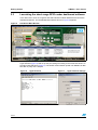
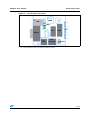
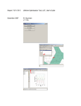
The dashboard of the short-range RFID reader is divided into five panels: “Mode Switch”,
“Mode Control”, “RTC Control”, “Memory Records” and “Runtime Log”. They are shown in
Figure 9.
In the “Mode Switch” panel, located at the center of the window, the user can switch modes
(Switch Mode button) or check (Get Mode button) the current operating mode of the reader.
The “Mode Control” panel, on the left-hand side of the window, contains controls for
Autonomous cycle setup and supervision: Auto Read Mode button, Auto Write Mode button,
AutoWrite Mode Phrase edit box and Start / Stop button.
The panel also accommodates the Download All and Erase All buttons used for the
maintenance of the Event Records stored in the onboard memory.
The three software LEDs that mirror the real-time behavior of the reader are also on the
“Mode Control” panel.
The “RTC Control” panel, located below the “Mode Switch” panel, contains the controls
related to the reader’s Real Time Clock (RTC) chip: Set Time and Get Time buttons.
By pressing the Sync w PC button the user can easily synchronize the onboard reader’s
time with the local PC/Laptop time.
The “Memory Records” panel, located at the bottom of the window, stores the information
received from the reader after the Download All button has been pressed.
The “Runtime Log” panel, on the right-hand side of the window, simply traces all the activity
managed by the Win32 Dashboard.
Figure 9.
Description of the main Dashboard window
Mode Control
14/19
Mode Switch
RTC Control
Memory Records
Runtime Log