1
UMC800 Controller
Modbus® RTU Serial Communications
User Manual
51-52-25-87A
2/01
Sensing and Control
Copyright, Notices, and Trademarks
Printed in U.S.A. – © Copyright 2001 by Honeywell
Revision A – 2/01
Warranty/Remedy
Honeywell warrants goods of its manufacture as being free of defective materials and faulty
workmanship. Contact your local sales office for warranty information. If warranted goods are
returned to Honeywell during the period of coverage, Honeywell will repair or replace without
charge those items it finds defective. The foregoing is Buyer’s sole remedy and is in lieu of all
other warranties, expressed or implied, including those of merchantability and fitness for a
particular purpose. Specifications may change without notice. The information we supply is
believed to be accurate and reliable as of this printing. However, we assume no responsibility for
its use.
While we provide application assistance personally, through our literature and the Honeywell web
site, it is up to the customer to determine the suitability of the product in the application.
Sensing and Control
Honeywell
11 West Spring Street
Freeport, IL 61032
Modbus is a registered trademark of MODICON, Inc.
Windows is an addressed trademark of Microsoft Inc.
The omission of a name from this list is not to be interpreted that the name is not a trademark.
Reference: Modicon Modbus Protocol Reference Guide - PI-MBUS-300 Rev. G
ii
UMC800 Modbus® RTU Serial Communications User Manual
2/01
About This Document
Abstract
This document provides information specific to Honeywell’s UMC800 Controller implementing the Modbus RTU
Serial Communications protocol. It includes a summary of all UMC800 data available (primarily floating point) for
Modbus RTU access, read and write including methods for access.
Contacts
World Wide Web
The following lists Honeywell’s World Wide Web sites that will be of interest to our sensing and control customers.
Honeywell Organization
WWW Address (URL)
Corporate
http://www.honeywell.com
Sensing and Control
http://www.honeywell.com/sensing
International
http://www.honeywell.com/Business/global.asp
Telephone
Contact us by telephone at the numbers listed below.
Organization
Phone Number
United States and Canada
Honeywell
1-800-423-9883
1-888-423-9883
1-800-525-7439
Asia Pacific
Honeywell Asia Pacific
Hong Kong
(852) 2829-8298
Europe
Honeywell PACE, Brussels, Belgium
[32-2] 728-2111
Latin America
Honeywell, Sunrise, Florida U.S.A.
(954) 845-2600
2/01
UMC800 Modbus® RTU Serial Communications User Manual
Tech. Support
Faxed documents
Service
iii
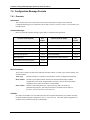
Contents
1.
INTRODUCTION ................................................................................................... 1
1.1
2.
Modbus RTU Implementation ....................................................................................................... 1
WIRING ................................................................................................................. 2
2.1
COMM A Connector ..................................................................................................................... 2
2.2
RS 485 serial communications....................................................................................................... 3
3.
MODBUS RTU MESSAGE FORMAT ................................................................... 4
3.1
Modbus RTU Link Layer............................................................................................................... 4
3.2
Modbus RTU Data Layer............................................................................................................... 5
3.3
IEEE 32-bit Floating Point Register Information .......................................................................... 6
4.
MODBUS RTU FUNCTION CODES ................................................................... 11
4.1
Function Code 01 – Read Digital Output Status.......................................................................... 13
4.2
Function Code 02 - Read Digital Input Status ............................................................................. 16
4.3
Function Codes 03/04 - Read Data Registers .............................................................................. 17
4.4
Function Code 05 - Force Single Digital Output ......................................................................... 18
4.5
Function Codes 06 - Preset Single Register................................................................................. 19
4.6
Function Code 08 - Loopback Message....................................................................................... 20
4.7
Function Codes 16 (10h) - Preset Multiple Registers.................................................................. 21
4.8
Function Code 17 (11h) - Report UMC800 ID............................................................................ 22
5.
MODBUS RTU EXCEPTION CODES................................................................. 24
6.
REGISTER MAP FOR PROCESS AND OPERATION TYPE VARIABLES....... 26
6.1
Register Map Overview ............................................................................................................... 26
6.2
Miscellaneous Register Map........................................................................................................ 28
6.3
Loop Value Register Map............................................................................................................ 29
6.4
Example for queries using Function Codes 3, 6, 16 .................................................................... 32
6.5
Analog Input, Frequency Input, Pulse Input Value Register Map............................................... 33
6.6
Variable Register Map ................................................................................................................. 34
6.7
Time Register Map....................................................................................................................... 35
6.8
Alarm Status Register Map .......................................................................................................... 36
6.9
Signal Tag Register Map.............................................................................................................. 37
6.10 Set Point Program Register Maps ................................................................................................ 38
6.11 Set Point Programmer Value Register Map................................................................................. 42
iv
UMC800 Modbus® RTU Serial Communications User Manual
2/01
6.12 Set Point Programmer Additional Values Register Map ............................................................. 43
6.13 Set Point Programmer Segment Map........................................................................................... 45
6.14 Segment Register Map ................................................................................................................. 45
6.15 Scheduler Value Register Map .................................................................................................... 47
6.16 Scheduler Segment Register Map ................................................................................................ 53
6.17 Segment Register Map ................................................................................................................. 54
6.18 Hand/OFF/Auto Control Group Register Map ............................................................................ 56
6.19 Device Control Group Register Map ........................................................................................... 57
7.
CONTROLLER CONFIGURATION MESSAGES
(FUNCTION CODES 20 AND 21)................................................................................. 58
7.1
Overview ...................................................................................................................................... 58
7.2
Function Code 20 – Read General Reference Data ..................................................................... 59
7.3
Function Code 21 – Write General Reference Data .................................................................... 66
7.4
Configuration Message Formats .................................................................................................. 68
8.
FUNCTION PARAMETER INDEX REFERENCE................................................ 88
8.1
Parameter Index Numbers............................................................................................................ 88
8.2
ABS Function Block .................................................................................................................... 91
8.3
ADD Function Block ................................................................................................................... 92
8.4
4ADD Function Block ................................................................................................................. 93
8.5
AI Function Block........................................................................................................................ 94
8.6
ALM Function Block ................................................................................................................... 95
8.7
2AND Function Block ................................................................................................................. 96
8.8
4AND Function Block ................................................................................................................. 97
8.9
8AND Function Block ................................................................................................................. 98
8.10 AMB Function Block................................................................................................................... 99
8.11 AO Function Block .................................................................................................................... 101
8.12 ASYS Function Block................................................................................................................ 102
8.13 BCD Function Block.................................................................................................................. 104
8.14 BOOL Function Block ............................................................................................................... 105
8.15 CARB Function Block ............................................................................................................... 106
8.16 CAVG Function Block............................................................................................................... 109
8.17 CMPR Function Block............................................................................................................... 110
8.18 DC Function Block .................................................................................................................... 111
8.19 DCMP Function Block............................................................................................................... 113
8.20 DENC Function Block ............................................................................................................... 114
8.21 DEWP Function Block............................................................................................................... 115
2/01
UMC800 Modbus® RTU Serial Communications User Manual
v
8.22 DI Function Block...................................................................................................................... 116
8.23 8 DI Function Block................................................................................................................... 117
8.24 DIV Function Block................................................................................................................... 118
8.25 DO Function Block .................................................................................................................... 119
8.26 8 DO Function Block ................................................................................................................. 120
8.27 DSW Function Block ................................................................................................................. 121
8.28 FGEN Function Block ............................................................................................................... 122
8.29 FI Function Block ...................................................................................................................... 124
8.30 FSS Function Block ................................................................................................................... 125
8.31 FSYS Function Block ................................................................................................................ 127
8.32 HLLM Function Block............................................................................................................... 128
8.33 HMON Function Block.............................................................................................................. 129
8.34 HOA Function Block ................................................................................................................. 130
8.35 HSEL Function Block................................................................................................................ 132
8.36 LDLG Function Block ............................................................................................................... 133
8.37 LMON Function Block .............................................................................................................. 134
8.38 LSEL Function Block ................................................................................................................ 135
8.39 LTCH Function Block ............................................................................................................... 136
8.40 MATH Function Block .............................................................................................................. 137
8.41 MBR Function Block ................................................................................................................. 138
8.42 MBS Function Block ................................................................................................................. 139
8.43 MBW Function Block................................................................................................................ 140
8.44 MDFL Function Block............................................................................................................... 141
8.45 MMA Function Block................................................................................................................ 142
8.46 MSF Function Block.................................................................................................................. 143
8.47 MUL Function Block ................................................................................................................. 144
8.48 4MUL Function Block ............................................................................................................... 145
8.49 NEG Function Block.................................................................................................................. 146
8.50 NOT Function Block.................................................................................................................. 147
8.51 ONDT Function Block............................................................................................................... 148
8.52 OFDT Function Block ............................................................................................................... 149
8.53 ON/OFF Function Block............................................................................................................ 150
8.54 2OR Function Block .................................................................................................................. 152
8.55 4OR Function Block .................................................................................................................. 153
8.56 8OR Function Block .................................................................................................................. 154
8.57 PI Function Block ...................................................................................................................... 155
8.58 PID Function Block.................................................................................................................... 157
8.59 PTMR Function Block............................................................................................................... 160
vi
UMC800 Modbus® RTU Serial Communications User Manual
2/01
8.60 RCP Function Block .................................................................................................................. 161
8.61 RH Function Block .................................................................................................................... 162
8.62 ROC Function Block.................................................................................................................. 163
8.63 RSW Function Block ................................................................................................................. 164
8.64 RTMR Function Block............................................................................................................... 165
8.65 SCB Function Block .................................................................................................................. 167
8.66 SPEV Function Block ................................................................................................................ 168
8.67 SPP Function Block ................................................................................................................... 170
8.68 SPS Function Block ................................................................................................................... 173
8.69 SPSA Function Block ................................................................................................................ 176
8.70 STFL Function Block................................................................................................................. 177
8.71 STSW Function Block ............................................................................................................... 178
8.72 SQRT Function Block................................................................................................................ 179
8.73 SUB Function Block .................................................................................................................. 180
8.74 4SUB Function Block ................................................................................................................ 181
8.75 SW Function Block.................................................................................................................... 182
8.76 TAHD Function Block............................................................................................................... 183
8.77 TGFF Function Block ................................................................................................................ 184
8.78 TOT Function Block .................................................................................................................. 185
8.79 TPO Function Block .................................................................................................................. 186
8.80 TPSC (3POS) Function Block ................................................................................................... 187
8.81 TRIG Function Block................................................................................................................. 190
8.82 UPDN Function Block ............................................................................................................... 191
8.83 VLIM Function Block................................................................................................................ 192
8.84 WTUN Function Block.............................................................................................................. 193
8.85 WVAR Function Block.............................................................................................................. 194
8.86 XFR Function Block .................................................................................................................. 195
8.87 XOR Function Block ................................................................................................................. 196
8.88 Variables .................................................................................................................................... 197
9.
BLOCK STATUS TYPES.................................................................................. 198
9.1
Overview .................................................................................................................................... 198
9.2
Block Status Values and Definitions ......................................................................................... 198
10.
DIAGNOSTICS AND TROUBLESHOOTING.................................................... 200
10.1 Overview .................................................................................................................................... 200
11.
2/01
APPENDIX: CRC-16 CALCULATION .............................................................. 201
UMC800 Modbus® RTU Serial Communications User Manual
vii
Tables
Table 3-1 Modbus RTU Message Formats ________________________________________________ 4
Table 3-2 IEEE Floating Point Number Examples in FP B Format_____________________________ 10
Table 4-1 Modbus RTU Function Codes Definitions _______________________________________ 11
Table 4-2 Maximum Number of Object Addresses _________________________________________ 12
Table 4-3 Maximum Number of Registers Allowable per Request _____________________________ 12
Table 4-4 Modbus Comm Digital I/O Channel to Address Mapping ___________________________ 14
Table 5-1 Modbus RTU Data Layer Status Exception Codes _________________________________ 25
Table 6-1 Global Register Map ________________________________________________________ 26
Table 6-2 Miscellaneous Register Map Addresses _________________________________________ 28
Table 6-3 Loop Value Register Map Addresses ___________________________________________ 29
Table 6-4 Analog Input, Frequency Input, Pulse Input Value Register Map Addresses _____________ 33
Table 6-5 Variable Register Map Addresses ______________________________________________ 34
Table 6-6 Time Register Map Addresses _________________________________________________ 35
Table 6-7 Alarm Status Register Map Addresses___________________________________________ 36
Table 6-8 Signal Tag Register Map Addresses ____________________________________________ 37
Table 6-9 Steps to Download a Setpoint Program using Modbus Function Codes 3, 4, 6, 16 ________ 40
Table 6-10 Steps to Download a Setpoint Program using Modbus Function Codes 20, 21 __________ 41
Table 6-11 Steps to Upload a Setpoint Program using Modbus Function Codes 3, 4, 6, 16 __________ 41
Table 6-12 Set Point Programmer Value Register Map Addresses _____________________________ 42
Table 6-13 Set Point Programmer Additional Values Register Map Addresses ___________________ 43
Table 6-14 Set Point Programmer Segment Map Addresses __________________________________ 45
Table 6-15 Segment Register Map Addresses _____________________________________________ 45
Table 6-16 Steps to Download a Setpoint Schedule using Modbus Function Codes 3, 4, 6, 16 _______ 48
Table 6-17 Steps to Download a Setpoint Schedule using Modbus Function Codes 20, 21 __________ 49
Table 6-18 Steps to Upload a Setpoint Schedule using Modbus Function Codes 3, 4, 6, 16 _________ 49
Table 6-19 Scheduler Value Register Map Addresses_______________________________________ 50
Table 6-20 Scheduler Segment Register Map Addresses_____________________________________ 53
Table 6-21 Segment Register Map Addresses _____________________________________________ 54
Table 6-22 HOA Control Group Register Map ____________________________________________ 56
Table 6-23 Device Control Group Register Map ___________________________________________ 57
Table 7-1 Setpoint Programmer Segment Data ____________________________________________ 73
Table 7-2 Contents of Alarm Mask Bytes ________________________________________________ 77
Table 7-3 Historical Record Format_____________________________________________________ 79
Table 7-4 Scheduler Segment Data Format _______________________________________________ 84
Table 7-5 Application Error Codes _____________________________________________________ 87
Table 8-1 Function Block Look-up Table ________________________________________________ 88
Table 8-2 ABS Dynamic Parameters ____________________________________________________ 91
Table 8-3 ADD Dynamic Parameters____________________________________________________ 92
Table 8-4 4ADD Dynamic Parameters___________________________________________________ 93
Table 8-5 AI Dynamic Parameters ______________________________________________________ 94
Table 8-6 AI Static Configuration Parameters _____________________________________________ 94
Table 8-7 ALM Dynamic Parameters ___________________________________________________ 95
Table 8-8 ALM Static Configuration Parameters __________________________________________ 95
Table 8-9 2AND Dynamic Parameters___________________________________________________ 96
Table 8-10 4AND Dynamic Parameters__________________________________________________ 97
Table 8-11 8AND Dynamic Parameters__________________________________________________ 98
Table 8-12 AMB Dynamic Values______________________________________________________ 99
Table 8-13 AMB Static Configuration Values____________________________________________ 100
viii
UMC800 Modbus® RTU Serial Communications User Manual
2/01
Table 8-14 AO Dynamic Parameters ___________________________________________________ 101
Table 8-15 ASYS Dynamic Parameters _________________________________________________ 102
Table 8-16 BCD Dynamic Parameters __________________________________________________ 104
Table 8-17 BOOL Dynamic Parameters_________________________________________________ 105
Table 8-18 CARB Dynamic Parameters_________________________________________________ 106
Table 8-19 CARB Static Configuration Parameters _______________________________________ 107
Table 8-20 CAVG Dynamic Parameters ________________________________________________ 109
Table 8-21 CMPR Dynamic Parameters ________________________________________________ 110
Table 8-22 DC Dynamic Parameters ___________________________________________________ 111
Table 8-23 DC Static Configuration Parameters___________________________________________ 112
Table 8-24 DCMP Dynamic Parameters ________________________________________________ 113
Table 8-25 DCMP Static Configuration Parameters _______________________________________ 113
Table 8-26 DENC Dynamic Parameters_________________________________________________ 114
Table 8-27 DEWP Dynamic Parameters ________________________________________________ 115
Table 8-28 DEWP Static Configuration Parameters _______________________________________ 115
Table 8-29 DI Dynamic Parameters ____________________________________________________ 116
Table 8-30 Eight DI Dynamic Parameters _______________________________________________ 117
Table 8-31 DIV Dynamic Parameters __________________________________________________ 118
Table 8-32 DO Dynamic Parameters ___________________________________________________ 119
Table 8-33 Eight DO Dynamic Parameters ______________________________________________ 120
Table 8-34 DSW Dynamic Parameters _________________________________________________ 121
Table 8-35 FGEN Dynamic Parameters _________________________________________________ 122
Table 8-36 FGEN Static Configuration Parameters________________________________________ 122
Table 8-37 FI Dynamic Parameters ____________________________________________________ 124
Table 8-38 FI Static Configuration Parameters ___________________________________________ 124
Table 8-39 FSS Dynamic Parameters___________________________________________________ 125
Table 8-40 FSYS Dynamic Parameters _________________________________________________ 127
Table 8-41 HLLM Dynamic Parameters ________________________________________________ 128
Table 8-42 HLLM Static Configuration Parameters _______________________________________ 128
Table 8-43 HMON Dynamic Parameters ________________________________________________ 129
Table 8-44 HOA Dynamic Parameters__________________________________________________ 130
Table 8-45 HOA Static Configuration Parameters_________________________________________ 131
Table 8-46 HSEL Dynamic Parameters _________________________________________________ 132
Table 8-47 LDLG Dynamic Parameters_________________________________________________ 133
Table 8-48 LMON Dynamic Parameters ________________________________________________ 134
Table 8-49 LSEL Dynamic Parameters _________________________________________________ 135
Table 8-50 LTCH Dynamic Parameters _________________________________________________ 136
Table 8-51 MATH Dynamic Parameters ________________________________________________ 137
Table 8-52 MBR Dynamic Parameters _________________________________________________ 138
Table 8-53 MBR Static Parameters ____________________________________________________ 138
Table 8-54 MBS Dynamic Parameters __________________________________________________ 139
Table 8-55 MBS Static Parameters ____________________________________________________ 139
Table 8-56 MBW Dynamic Parameters _________________________________________________ 140
Table 8-57 MBW Static Parameters____________________________________________________ 140
Table 8-58 MDFL Dynamic Parameters ________________________________________________ 141
Table 8-59 MMA Dynamic Parameters _________________________________________________ 142
Table 8-60 MSF Dynamic Parameters __________________________________________________ 143
Table 8-61 MSF Static Configuration Parameters _________________________________________ 143
Table 8-62 MUL Dynamic Parameters _________________________________________________ 144
Table 8-63 4MUL Dynamic Parameters ________________________________________________ 145
2/01
UMC800 Modbus® RTU Serial Communications User Manual
ix
Table 8-64 NEG Dynamic Parameters __________________________________________________ 146
Table 8-65 NOT Dynamic Parameters __________________________________________________ 147
Table 8-66 ONDT Dynamic Parameters ________________________________________________ 148
Table 8-67 ONDT Static Parameters ___________________________________________________ 148
Table 8-68 OFDT Dynamic Parameters _________________________________________________ 149
Table 8-69 ONDT Static Parameters ___________________________________________________ 149
Table 8-70 ON/OFF Dynamic Parameters _______________________________________________ 150
Table 8-71 ON/OFF Static Configuration Parameters ______________________________________ 151
Table 8-72 2OR Dynamic Parameters __________________________________________________ 152
Table 8-73 4OR Dynamic Parameters __________________________________________________ 153
Table 8-74 8OR Dynamic Parameters __________________________________________________ 154
Table 8-75 PI Dynamic Parameters ____________________________________________________ 155
Table 8-76 PI Static Configuration Parameters ___________________________________________ 156
Table 8-77 PID Dynamic Parameters ___________________________________________________ 157
Table 8-78 PID Modes ______________________________________________________________ 158
Table 8-79 PID Static Configuration Parameters __________________________________________ 158
Table 8-80 PTMR Dynamic Parameters ________________________________________________ 160
Table 8-81 RCP Dynamic Parameters __________________________________________________ 161
Table 8-82 RH Dynamic Parameters ___________________________________________________ 162
Table 8-83 ROC Dynamic Parameters __________________________________________________ 163
Table 8-84 ROC Static Configuration Parameters _________________________________________ 163
Table 8-85 RSW Dynamic Parameters__________________________________________________ 164
Table 8-86 RTMR Dynamic Parameters ________________________________________________ 165
Table 8-87 RTMR Static Configuration Parameters _______________________________________ 166
Table 8-88 SCB Dynamic Parameters __________________________________________________ 167
Table 8-89 SPEV Dynamic Parameters _________________________________________________ 168
Table 8-90 SPP Dynamic Contained Parameters __________________________________________ 170
Table 8-91 SPP Dynamic Output Parameters_____________________________________________ 171
Table 8-92 SPP Dynamic Input Parameters ______________________________________________ 172
Table 8-93 SPS Dynamic Contained Parameters __________________________________________ 173
Table 8-94 SPS Dynamic Output Parameters_____________________________________________ 174
Table 8-95 SPS Dynamic Input Parameters ______________________________________________ 174
Table 8-96 SPS Static Configuration Parameters__________________________________________ 175
Table 8-97 SPSA Dynamic Parameters _________________________________________________ 176
Table 8-98 STFL Dynamic Values_____________________________________________________ 177
Table 8-99 STSW Dynamic Values ____________________________________________________ 178
Table 8-100 SQRT Dynamic Parameters ________________________________________________ 179
Table 8-101 SUB Dynamic Parameters _________________________________________________ 180
Table 8-102 4SUB Dynamic Parameters ________________________________________________ 181
Table 8-103 SW Dynamic Parameters __________________________________________________ 182
Table 8-104 TAHD Dynamic Parameters _______________________________________________ 183
Table 8-105 TGFF Dynamic Parameters ________________________________________________ 184
Table 8-106 TOT Dynamic Parameters _________________________________________________ 185
Table 8-107 TOT Static Configuration Parameters ________________________________________ 185
Table 8-108 TPO Dynamic Parameters _________________________________________________ 186
Table 8-109 TPSC Dynamic Parameters ________________________________________________ 187
Table 8-110 TPSC Static Configuration Parameters _______________________________________ 188
Table 8-111 TRIG Dynamic Parameters ________________________________________________ 190
Table 8-112 UPDN Dynamic Parameters________________________________________________ 191
Table 8-113 UPDN Static Configuration Parameters ______________________________________ 191
x
UMC800 Modbus® RTU Serial Communications User Manual
2/01
Table 8-114 VLIM Dynamic Parameters ________________________________________________ 192
Table 8-115 VLIM Static Configuration Parameters _______________________________________ 192
Table 8-116 WTUN Dynamic Parameters _______________________________________________ 193
Table 8-117 WVAR Dynamic Parameters _______________________________________________ 194
Table 8-118 XFR Dynamic Parameters _________________________________________________ 195
Table 8-119 XFR Static Configuration Parameters ________________________________________ 195
Table 8-120 XOR Dynamic Parameters _________________________________________________ 196
Table 8-121 Variables ______________________________________________________________ 197
Table 9-1 Block Status Values ________________________________________________________ 198
Table 10-1 Modbus Communications Troubleshooting_____________________________________ 200
2/01
UMC800 Modbus® RTU Serial Communications User Manual
xi
Figures
Figure 2-1 COMM A port wiring (2-wire and 4-wire)________________________________________ 2
Figure 2-2 RS 485 port wiring (2 wire) ___________________________________________________ 3
Figure 3-1 IEEE Floating Point Data format _______________________________________________ 6
Figure 3-2 IEEE Floating Point Formats _________________________________________________ 10
Figure 7-1 Read Contiguous 32-Bit Request and Response Message Formats ____________________ 69
Figure 7-2 Read Scattered 32-Bit Request and Response Message Formats ______________________ 70
Figure 7-3 Write Scattered 32-Bit Request and Response Message Formats _____________________ 71
Figure 7-4 Read Setpoint Program Segment ______________________________________________ 72
Figure 7-5 Write Setpoint Program Segment ______________________________________________ 74
Figure 7-6 Read Alarm Point Detail_____________________________________________________ 75
Figure 7-7 Write Alarm Acknowledge ___________________________________________________ 76
Figure 7-8 Historical Data Upload ______________________________________________________ 78
Figure 7-9 Historical Data Upload Acknowledge __________________________________________ 80
Figure 7-10 Event Summary___________________________________________________________ 81
Figure 7-11 Event Acknowledge _______________________________________________________ 82
Figure 7-12 Read Setpoint Scheduler Segment ____________________________________________ 83
Figure 7-13 Write Setpoint Scheduler Segment ____________________________________________ 85
Figure 7-14 Loopback Request and Response Message Formats ______________________________ 86
xii
UMC800 Modbus® RTU Serial Communications User Manual
2/01
Introduction
1. Introduction
1.1 Modbus RTU Implementation
Overview
This implementation is designed to provide a popular data exchange format connecting the UMC800 Slave
Port (COM A) to both Honeywell and foreign master devices. The Modbus RTU allows the instrument to
be a citizen on a data link shared with other devices which subscribe to the Modbus RTU RS-485
specification.
These instruments DO NOT emulate any MODICON type device. The Modbus RTU specification is
respected in the physical and data link layers. The message structure of the Modbus RTU function codes are
employed and standard IEEE 32-bit floating point and integer formats are used. Data register mapping is
unique to these instruments. The definition in Table 6-1 is the register mapping for the UMC800 and the
corresponding parameter value.
Function Codes 20 and 21
Also included in this manual is information concerning function codes 20 and 21 in Section 7. They provide
additional functionality not available using the function codes described in Section 4. The additional
functionality includes:
•
read/write function block dynamic data that is not part of the function code 03 register set
•
read function block inputs and outputs that are not part of the function code 03 register set
•
read detail of an alarm point
•
read the event summary buffer
•
acknowledge alarms and events
•
upload historical data for alarms and events
ATTENTION
To access the controller you must have a current Control Builder configuration file available. Data is
referenced relative to function block number and the index number of the desired parameter. It is
suggested that you upload the controller configuration using the Control Builder configuration tool to assure
that you have a current configuration. The Control Builder tool can provide a printout of all function blocks
used, their number and detail. You will also need to use the Control Builder Function Block Reference
Guide as a reference for the function block index numbers for contained parameters.
2/01
UMC800 Modbus® RTU Serial Communications User Manual
1
Wiring
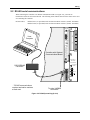
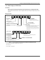
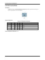
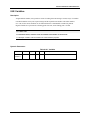
2. Wiring
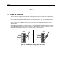
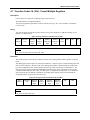
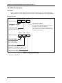
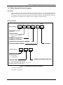
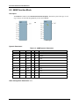
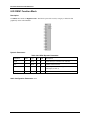
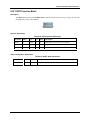
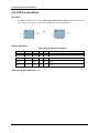
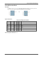
2.1 COMM A Connector
The CPU module equipped with the optional communication board provides an RS 485 communications
ports with Modbus RTU protocol support. COMM A port allows the UMC800 controller to network with
up to 31 other slave UMC800 controllers and devices on a Modbus RTU link. This manual describes the
communications for the COM A Port only. COM B is a master port described in other product literature.
Figure 2-1 shows the COMM A connector wiring when using either a shielded twisted pair or 4-wire
shielded cable.
NOTE: When using the RS 485 communications, it is recommended that an RS 485 to RS 232 converter
(such as Black Box model IC901A) be used to interface with the host PC. Also, be certain that the Half
Duplex Turnaround Delay parameter for the converter set to 1 millisecond or less.
+
Receive _
+
Transmit _
Shield
+
Receive _
+
Transmit _
COMM A
Shield
4-Wire
Shielded
COMM A
2-Wire
Shielded
Figure 2-1 COMM A port wiring (2-wire and 4-wire)
2
UMC800 Modbus® RTU Serial Communications User Manual
2/01
Wiring
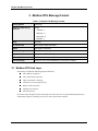
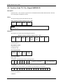
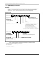
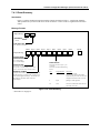
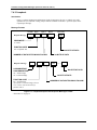
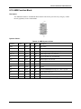
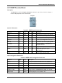
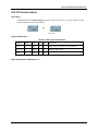
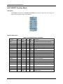
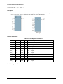
2.2 RS 485 serial communications
When connecting the controller to an RS 485 communication link (see Figure 2-2), you must use
termination resistors at each end of the link. The following cables with the listed resistor values can be used
for connecting the controller.
RS 485 Cables:
Belden #9271 (or equivalent) with 120 ohm termination resistors (2,000 ft. maximum)
Belden #9182 (or equivalent) with 150 ohm termination resistors (4,000 ft. maximum)
OFFLINE
RUN
CONFIGURATION
PROGRAM
Host
Computer
POWER
LoBAT
FORCE
DISPLAY
Controller with Optional
Communications Board
Repl ace battery with Tadiran TL5101/S
only. Use of another battery may
present a risk of fire or expl osion.
See users guide for instructions.
RUN
BAT
_
100 - 240 V ~
50 / 60 Hz
100 VA MAX.
RS232/RS485
Converter *
L1
L2 / N
COMM B
COMM A
F 3,15 AT
250V
* RS 485 communications
requires termination resistors
at each end.
To other UMC800
Controllers *
Figure 2-2 RS 485 port wiring (2 wire)
2/01
UMC800 Modbus® RTU Serial Communications User Manual
3
Modbus RTU Message Format
3. Modbus RTU Message Format
Table 3-1 Modbus RTU Message Formats
Coding system
8 bit binary
Number of data bits per
character
10 Bits
start bits - 1
data bits - 8
parity bits - 0
stop bits - 1
Parity
Not used
Bit transfer rate
9600, 19200, 38400 Selectable
Duplex
Half duplex Transceiver
Error checking
CRC (cyclic redundancy check)
Polynomial
(CRC-16 10100000000001)
Bit transfer order
LSB first
End of message
Idle line for 3.5 or more characters (>1.82 msec for 19200).
3.1 Modbus RTU Link Layer
The link layer includes the following properties/behaviors:
n
Slave address recognition,
n
Start / End of Frame detection,
n
CRC-16 generation / checking,
n
Transmit / receive message time-out,
n
Buffer overflow detection,
n
Framing error detection,
n
Idle line detection.
Errors detected by the physical layer in messages received by the slave are ignored and the physical layer
automatically restarts by initiating a new receive on the next idle line detection.
4
UMC800 Modbus® RTU Serial Communications User Manual
2/01
Modbus RTU Message Format
General Modbus RTU message format
Query message format
[Slave Address, Function Code, Function code dependent data, CRC 16]
Response message format
[Slave Address, Function Code*, Function code dependent data, CRC 16]
* If an error is detected in a valid message the response function code is modified by adding 80 (hex) and the
function code dependent data is replaced by an exception response code as described in Section 5 - Modbus RTU
Exception Codes.
Between messages, the RS-485 link is in a high impedance state. During this time receiving devices are
more susceptible to noise generated false start of messages. Although noise-generated messages are rejected
due to address, framing, and CRC checking, they can cause the loss of a good message when they are
included in the message stream. In the slave the transmitting device enables its transmitter line diver and
forces an idle line state onto the link for three character time slots prior to transmitting. This forces
termination of any noise generated messages and improves message frame synchronization.
3.2 Modbus RTU Data Layer
The data layer includes:
•
Diagnostic loopback,
•
Function code recognition / rejection,
•
Busy / repoll,
•
Data error code generation
Errors detected by the data layer are rejected and the slave responds to the polling device with a Modbustype status exception error. A summary of the Modbus status exception codes is listed in Section 5 Modbus RTU Exception Codes.
2/01
UMC800 Modbus® RTU Serial Communications User Manual
5
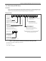
Modbus RTU Message Format
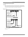
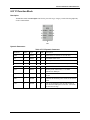
3.3 IEEE 32-bit Floating Point Register Information
The Modbus applications support IEEE 32-bit floating point information for several of the function codes.
3.3.1 IEEE Floating Point Data Format
The formula for calculating the floating point number is:
mantissa x 2
(exponent -127)
(23 bit signed binary with 8 bit biased binary exponent)
byte 4
byte 3
3
2 2
1
1
4 3
6
xxxxxxxx x.xxxxxxx
byte 2
1
5
8
xxxxxxxx
byte 1
7
0
xxxxxxx
mantissa (23 bits)
implied binary point for mantissa
exponent (8 bit unsigned value)
sign of the mantissa 0 = positive, 1 = negative
Figure 3-1 IEEE Floating Point Data format
Mantissa and Sign
The mantissa is defined by a sign bit (31) and a 23-bit binary fraction. This binary fraction is combined with
an “implied” value of 1 to create a mantissa value, which is greater than or equal to 1.0 and less than 2.0.
The mantissa is positive if the sign bit is zero (reset), and negative if the sign bit is one (set). For example:
DECIMAL
HEXADECIMAL
BINARY
100
42C80000
01000010 11001000 00000000 00000000
The sign bit (31) is zero, indicating a positive mantissa. Removing the sign bits and exponent bits, the
mantissa becomes:
HEXADECIMAL
BINARY
480000
xxxxxxxx x1001000 00000000 00000000
Add an “implied” value of one to the left of the binary point:
BINARY
1.1001000 00000000 00000000
Using positioned notation, this binary number is equal to:
1.0 + (1x2 -1 ) + (0x2 -2 ) + (0x2 -3 ) + (1x2 -4 ) = 10
. + 0.5 + 0.0 + 0.0 + 0.0625 = 15625
.
6
UMC800 Modbus® RTU Serial Communications User Manual
2/01
Modbus RTU Message Format
Exponent
The exponent is defined by an unsigned 8-bit binary value (bits 23 through 30). The value of the exponent
is derived by performing a signed subtraction of 127 (decimal) from the 8-bit exponent value.
DECIMAL
HEXADECIMAL
BINARY
100
42C80000
01000010 11001000 00000000 00000000
Removing the sign and mantissa bits, the exponent becomes:
DECIMAL
HEXADECIMAL
BINARY
133
85
x1000010 1xxxxxxx xxxxxxxx xxxxxxxx
or:
1x2 7 + 0x2 6 + 0x2 5 + 0x2 4 + 0x2 3 + 1x2 2 + 0x2 1 + 1x2 0
Subtract a bias of 127 (decimal) from the exponent to determine its value: 133 – 127 = 6.
Mantissa and Exponent Combination
Combining the mantissa and exponent from the two previous examples:
float number = mantissa x 2 exponent
float number = 1.5625 x 2 6 = 15625
.
x 64 = 100.0
Below is a list of sample float values in IEEE format:
DECIMAL
2/01
HEXADECIMAL
100.0
42C80000
-100.0
C2C80000
0.5
3F000000
-1.75
BFE00000
0.0625
3D800000
1
3F800000
0
00000000
UMC800 Modbus® RTU Serial Communications User Manual
7
Modbus RTU Message Format
Reserved Operands
Per the Standard certain exceptional forms of floating point operands are excluded from the numbering
system. These are as follows:
EXCEPTION
EXPONENT
MANTISSA
+/- Infinity
All 1’s
All 0’s
Not-a-Number (NAN)
All 1’s
Other than 0’s
Denormalized Number
All 0’s
Other than 0’s
Zero
All 0’s
All 0’s
3.3.2 Modbus Double Register Format
Each IEEE 32-bit floating point number requires two consecutive registers (four bytes) starting with the
register defined as the starting register for the information. The stuffing order of the bytes into the two
registers differs among Modbus hosts. To provide compatibility, the UMC800 Double register format is
configurable. To set the controller’s double register byte order, go to the “Set Controller Comm A Port”
dialog box in the User Utility/Control Builder and configure “Modbus Double Register Format”.
The selections are:
Selection
Description
Byte order
(See Figure 3-1)
FP B
Floating Point Big Endian Format
4, 3, 2, 1
FP BB
Floating Point Big Endian with
byte-swapped
3, 4, 1, 2
FP L
Floating Point Little Endian Format
1, 2, 3, 4
FP LB
Floating Point Little Endian with
byte-swapped
2, 1, 4, 3
Notes
UMC800 default
Modicon and
Wonderware
standard
See IEEE Formats starting on next page.
NOTE: Byte Swapping only applies to Function Codes 3, 4, and 16. Function Codes 20 and 21 DO NOT
support byte swapping. They always use FP B.
8
UMC800 Modbus® RTU Serial Communications User Manual
2/01
Modbus RTU Message Format
IEEE Floating Point Formats
FP B - Floating Point Big Endian Format:
Bit 0
Bit 31
M7 M6 M5 M4 M3 M2 M1 M0
E0 M22 M21M20 M19 M18 M17 M16
M15 M14 M13 M12 M11 M10 M9 M8
S E7 E6 E5 E4 E3 E2 E1
High
Low
High
Low
REGISTER N+1
(Low)
REGISTER N
(High)
S=Sign E=Exponent M=Mantissa
FP BB - Floating Point Big Endian with Byte Swapped Format:
Bit 24
Bit 31
Bit 15
S E7 E6 E5 E4 E3 E2 E1
Bit 16
Bit 23
M15 M14 M13 M12 M11 M10 M9 M8
Bit 7
Bit 0
M7 M6 M5 M4 M3 M2 M1 M0
E0 M22 M21M20 M19 M18 M17 M16
High
Bit 8
Low
High
Low
REGISTER N+1
(Low)
REGISTER N
(High)
S=Sign E=Exponent M=Mantissa
continued next page
2/01
UMC800 Modbus® RTU Serial Communications User Manual
9
Modbus RTU Message Format
FP L - Floating Point Little Endian Format:
Bit 15
Bit 8
S E7 E6 E5 E4 E3 E2 E1
M15 M14 M13 M12 M11 M10 M9 M8
Bit 7
E0 M22 M21M20 M19 M18 M17 M16
M7 M6 M5 M4 M3 M2 M1 M0
High
Bit 16
Bit 23
Bit 0
Bit 24
Bit 31
Low
High
Low
REGISTER N+1
(Low)
REGISTER N
(High)
S=Sign E=Exponent M=Mantissa
FP LB - Floating Point Little Endian with Byte Swapped Format:
Bit 7
M7 M6 M5 M4 M3 M2 M1 M0
Bit 15
Bit 8
E0 M22 M21M20 M19 M18 M17 M16
Bit 24
Bit 31
S E7 E6 E5 E4 E3 E2 E1
M15 M14 M13 M12 M11 M10 M9 M8
High
Bit 16
Bit 23
Bit 0
Low
High
Low
REGISTER N+1
(Low)
REGISTER N
(High)
S=Sign E=Exponent M=Mantissa
Figure 3-2 IEEE Floating Point Formats
Table 3-2 IEEE Floating Point Number Examples in FP B Format
10
IEEE FP B
Register N
Register N+1
Value
(decimal)
MSB LSB
100.0
42C80000h
42h
C8h
00h
00h
55.32
425D47AEh
42h
5Dh
47h
AEh
2.0
40000000h
40h
00h
00h
00h
1.0
3F800000h
3Fh
80h
00h
00h
-1.0
BF800000h
BFh
80h
00h
00h
high
low
high
low
UMC800 Modbus® RTU Serial Communications User Manual
2/01
Modbus RTU Function Codes
4. Modbus RTU Function Codes
The Honeywell Universal Modbus RTU protocol uses a subset of the standard Modbus RTU function codes to
provide access to process-related information. These standard function codes provide basic support for IEEE 32-bit
floating point numbers and 16-bit integer register representation of instrument’s process data.
Table 4-1, Table 4-2, and Table 4-3 list the Modbus RTU Function Code definitions, the maximum number of
Object Addresses and maximum number of registers allowed per request.
Repolling of data is not supported by this instrument.
Table 4-1 Modbus RTU Function Codes Definitions
Function Code
Name
Usage
01
Read Coil Status
Read the state of a digital output
02
Read Input Status
Read the state of a digital input
03
Read Holding Registers /
04
Read Input Registers
Read Data in 16 bit Register Format (high/low). Used to
read integer or floating point process data. Registers are
consecutive and are imaged from the instrument to the
host.
05
Force Single Coil
Write data to force a digital output ON/OFF
Values of FF 00 forces digital output ON
Values of 00 00 forces digital output OFF
Values of FF FF releases the force of the digital output
All other values are illegal and will not effect the digital
output.
06
Preset Single Register
Write Data in 16-bit Integer Format (high/low) ONLY.
08
Loopback Test
Used for diagnostic testing of the communications port.
16 (10h)
Preset Multiple Registers
Write Data in 16-bit Format (high/low). Used to write
integer and floating point override data. Registers are
consecutive and are imaged from the host to the
instrument.
17 (11h)
Report Device ID
Read instrument ID and connection information, ROM
version, etc.
20 (14h)
Read General Reference
Used to Read or upload the instrument’s configuration
into the host device. See Section 7.2.
21 (15h)
Write General Reference
Used to Write or download an instrument’s configuration
into the instrument from a host device. See Section 7.3.
2/01
UMC800 Modbus® RTU Serial Communications User Manual
11
Modbus RTU Function Codes
Table 4-2 Maximum Number of Object Addresses
Object Name
Max. No. of
Addresses
Object Name
Max. No. of
Addresses
Alarms Status
120
Variable Value
150
Analog Input
64
Set Point
Programmer Value
4
Analog Output
16
Segments per Set
Point Programmer
50
Discrete Input
96
Tagged Signals
500
Discrete
Output/Coil
96
Scheduler Value
1
Loop
16
Segments per
Scheduler Schedule
50
Table 4-3 Maximum Number of Registers Allowable per Request
Function
Code
12
Max. No. of
Registers
1, 2
12 Bytes
3, 4
127 Registers
63 Floats
5
1 Digital Output
6
1 Register
10h
127 Registers
63 Floats
UMC800 Modbus® RTU Serial Communications User Manual
2/01
Modbus RTU Function Codes
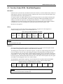
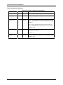
4.1 Function Code 01 – Read Digital Output Status
Description
Function code 01 (0X references) is used to read a digital output’s ON/OFF status of the UMC800 in a
binary data format. All binary data transferred using function code 01is mapped into bytes.
Broadcast is not supported.
Query
The query message specifies the starting Digital Output (DO) and the quantity of DOs to read. The DO
address in the message is based on the slot and channel number of the digital output being read. Table 4-4
shows the Modbus Comm Digital I/O Channel to Address Mapping.
Query message format for function code 01
Slave
Address
Function
Code
Starting
Address
High
Starting
Address
Low
Number
DO
High
Number
DO
Low
CRC
CRC
Example: Read DO channels 1 to 6, located in slot 1, from slave at address 02.
02 01 00 00 00 06 CRC CRC
Response
The DO status in the response message is packed as one DO per bit of the data field. Status is indicated as:
1 = ON; 0 = OFF. The LSB of the first data byte contains the DO addressed in the query. The other DOs
follow toward the high order end of this byte, and from low order to high order in subsequent bytes.
If the returned DO quantity is not a multiple of eight, the remaining bits in the final data byte will be padded
with zeros (toward the high order end of the byte). The byte count field specifies the quantity of data bytes
returned.
Response message format for function code 01
Slave
Address
Function
Code
Byte
Count
Data
Data
...
CRC
CRC
Example: DO channels 2 through 6 located in slot 1 are on, all others are off.
02 01 01 22 CRC CRC
In the response the status of DOs 1 - 6 is shown as the byte value 22 hex, or 0010 0010 binary. DO 8 is the
MSB of this byte, and DO 1 is the LSB. Left to right, the status of DO 6 through 1 is: ON-OFF-OFF-OFFON-OFF. DO #8 and #7 were not requested and so bit #7 or the MSB and bit #6 were padded with a 0.
2/01
UMC800 Modbus® RTU Serial Communications User Manual
13
Modbus RTU Function Codes
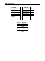
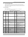
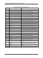
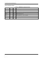
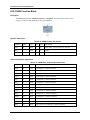
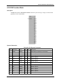
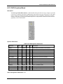
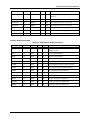
Table 4-4 Modbus Comm Digital I/O Channel to Address Mapping
Slot 1
CH#
Slot 2
Address
Dec
Hex
16
15
15
15
14
14
13
13
CH#
Slot 3
Address
Dec
Hex
16
31
1F
14
15
30
13
14
29
12
12
13
28
12
11
11
12
11
10
10
11
10
9
9
9
8
8
7
7
CH#
Slot 4
Address
Dec
Hex
16
47
2F
1E
15
46
1D
14
45
1C
13
44
27
1B
12
26
1A
11
10
25
19
8
9
24
7
8
23
6
6
7
6
5
5
5
4
4
3
3
CH#
Address
Dec
Hex
16
63
3F
2E
15
62
3E
2D
14
61
3D
2C
13
60
3C
43
2B
12
59
3B
42
2A
11
58
3A
10
41
29
10
57
39
18
9
40
28
9
56
38
17
8
39
27
8
55
37
22
16
7
38
26
7
54
36
6
21
15
6
37
25
6
53
35
4
5
20
14
5
36
24
5
52
34
3
4
19
13
4
35
23
4
51
33
2
2
3
18
12
3
34
22
3
50
32
2
1
1
2
17
11
2
33
21
2
49
31
1
0
0
1
16
10
1
32
20
1
48
30
Slot 5
CH#
Slot 6
Address
Dec
Hex
16
79
4F
15
78
14
77
13
76
12
11
CH#
Slot 7
Address
Dec
Hex
16
95
5F
4E
15
94
4D
14
93
4C
13
92
75
4B
12
74
4A
11
10
73
49
9
72
8
7
CH#
Slot 8
Address
Dec
Hex
16
111
6F
5E
15
110
5D
14
109
5C
13
108
91
5B
12
90
5A
11
10
89
59
48
9
88
71
47
8
70
46
7
6
69
45
5
68
4
67
3
CH#
Address
Dec
Hex
16
127
7F
6E
15
126
7E
6D
14
125
7D
6C
13
124
7C
107
6B
12
123
7B
106
6A
11
122
7A
10
105
69
10
121
79
58
9
104
68
9
120
78
87
57
8
103
67
8
119
77
86
56
7
102
66
7
118
76
6
85
55
6
101
65
6
117
75
44
5
84
54
5
100
64
5
116
74
43
4
83
53
4
99
63
4
115
73
66
42
3
82
52
3
98
62
3
114
72
2
65
41
2
81
51
2
97
61
2
113
71
1
64
40
1
80
50
1
96
60
1
112
70
Slots 9 through 16 on next page
14
UMC800 Modbus® RTU Serial Communications User Manual
2/01
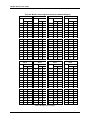
Modbus RTU Function Codes
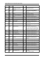
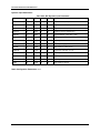
Slot 9
CH#
Slot 10
Address
Dec
CH#
Hex
Address
Dec
CH#
Hex
Slot 12
Address
Dec
CH#
Address
Hex
Dec
Hex
16
143
8F
16
159
9F
16
175
AF
16
191
BF
15
142
8E
15
158
9E
15
174
AE
15
190
BE
14
141
8D
14
157
9D
14
173
AD
14
189
BD
13
140
8C
13
156
9C
13
172
AC
13
188
BC
12
139
8B
12
155
9B
12
171
AB
12
187
BB
11
138
8A
11
154
9A
11
170
AA
11
186
BA
10
137
89
10
153
99
10
169
A9
10
185
B9
9
136
88
9
152
98
9
168
A8
9
184
B8
8
135
87
8
151
97
8
167
A7
8
183
B7
7
134
86
7
150
96
7
166
A6
7
182
B6
6
133
85
6
149
95
6
165
A5
6
181
B5
5
132
84
5
148
94
5
164
A4
5
180
B4
4
131
83
4
147
93
4
163
A3
4
179
B3
3
130
82
3
146
92
3
162
A2
3
178
B2
2
129
81
2
145
91
2
161
A1
2
177
B1
1
128
80
1
144
90
1
160
A0
1
176
B0
Slot 13
CH#
2/01
Slot 11
Slot 14
Address
CH#
Slot 15
Address
CH#
Slot 16
Address
CH#
Address
Dec
Hex
Dec
Hex
Dec
Hex
Dec
Hex
16
207
CF
16
223
DF
16
239
EF
16
255
FF
15
206
CE
15
222
DE
15
238
EE
15
254
FE
14
205
CD
14
221
DD
14
237
ED
14
253
FD
13
204
CC
13
220
DC
13
236
EC
13
252
FC
12
203
CB
12
219
DB
12
235
EB
12
251
FB
11
202
CA
11
218
DA
11
234
EA
11
250
FA
10
201
C9
10
217
D9
10
233
E9
10
249
F9
9
200
C8
9
216
D8
9
232
E8
9
248
F8
8
199
C7
8
215
D7
8
231
E7
8
247
F7
7
198
C6
7
214
D6
7
230
E6
7
246
F6
6
197
C5
6
213
D5
6
229
E5
6
245
F5
5
196
C4
5
212
D4
5
228
E4
5
244
F4
4
195
C3
4
211
D3
4
227
E3
4
243
F3
3
194
C2
3
210
D2
3
226
E2
3
242
F2
2
193
C1
2
209
D1
2
225
E1
2
241
F1
1
192
C0
1
208
D0
1
224
E0
1
240
F0
UMC800 Modbus® RTU Serial Communications User Manual
15
Modbus RTU Function Codes
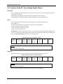
4.2 Function Code 02 - Read Digital Input Status
Description
Function code 02 (1X references) is used to read a digital input’s ON/OFF status of the UMC800 in a
binary data format. All binary data transferred using function code 02 is mapped into bytes.
Broadcast is not supported.
Query
The query message specifies the starting input and the quantity of inputs to read. The DI address in the
message is based on the slot and channel number of the digital input being read.
Query message format for function code 02
Slave
Address
Function
Code
Starting
Address
High
Starting
Address
Low
Number
Inputs
High
Number
Inputs
Low
CRC
CRC
Example: Read inputs for channels 1 to 6 in slot 1, from slave at address 02.
02 02 00 00 00 06 CRC CRC
Response
The input status in the response message is packed as one input per bit of the data field. Status is indicated
as: 1 = ON; 0 = OFF. The LSB of the first data byte contains the input addressed in the query. The other
inputs follow toward the high order end of this byte, and from low order to high order in subsequent bytes.
If the returned input quantity is not a multiple of eight, the remaining bits in the final data byte will be
padded with zeros (toward the high order end of the byte). The byte count field specifies the quantity of
data bytes returned. Table 4-4 shows the Modbus Comm Digital I/O Channel to Address Mapping.
Response message format for function code 02
Slave
Address
Function
Code
Byte
Count
Data
Data
...
CRC
CRC
Example: Inputs for channels 2 and 6 in slot 1 are on, all others are off.
02 02 01 22 CRC CRC
In the response the status of inputs 1 - 6 is shown as the byte value 22 hex, or 0010 0010 binary. Input 8 is
the MSB of this byte, and input 1 is the LSB. Left to right, the status of input 6 through 1 is: ON-OFF-OFFOFF-ON-OFF. Input #8and #7 were not requested and so bit #7or the MSB and bit #6 were padded with a
0.
16
UMC800 Modbus® RTU Serial Communications User Manual
2/01
Modbus RTU Function Codes
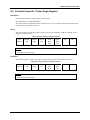
4.3 Function Codes 03/04 - Read Data Registers
Description
Function code 03 (4X references) or Function code 04 (3X references) is used to read the binary contents of
input registers in the slave referenced in Section 5. Function codes 3 and 4 are not restricted to inputs. They
may transmit alarm status, control parameters, etc.
If a request is made to an address that does not exist in the map in Section 6, the controller will honor that
request and return zeros for that address. This behavior will greatly enhance the bandwidth on the link vs.
making several different requests for non-contiguous data elements. (i.e. Consider a controller that is
configured for AI #1 and AI #3 and for some reason AI #2 is an invalid request.) The contiguous method
would allow the read of AI #1 through AI #3 and the data location for AI #2 would be zeros.
Broadcast is not supported.
Query
The query message specifies the starting register and quantity of registers to be read. Registers are
addressed starting at zero: registers 1-16 are addressed as 0-15.
Query message format for function code 03/04
Slave
Address
Function
Code
Starting
Address
High
Starting
Address
Low
Number
Addresses
High
Number
Addresses
Low
CRC
CRC
Example: Read analog inputs #1 and #2 in addresses 1800-1803 as floating point values from a slave at address 02.
02 04 18 00 00 04 CRC CRC
Response
The register data in the response message are packed as two bytes per register. For each register, the first
byte contains the high order bits and the second contains the low order bits.
The floating point values require two consecutive registers. A request for a single floating point value must
be for two registers. The byte order of the floating point number is determined by the setting of the byte
swap configuration value. In this example, and the examples that follow, the byte swap order is FP B. Refer
to subsection 3.3. The first 16 bits of the response contain the IEEE MSB of the float value. The second 16
bits of the response contain the IEEE LSB of the float value. If the master station requests only one register
at an address of a floating point value, a zero will be returned.
The Modbus RTU protocol has a single byte count for function codes 03 and 04, therefore the Modbus
RTU protocol can only process up to 64 floating point and 127 integer values in a single request.
Response message format for function codes 03/04
Slave
Address
Function
Code
Byte
Count
Data
Data
...
CRC
CRC
Example: Analog inputs #1 and #2 as floating point values where AI #1 = 100.0 and AI #2 = 55.32
02 04 08 42 C8 00 00 42 5D 47 AE CRC CRC
2/01
UMC800 Modbus® RTU Serial Communications User Manual
17
Modbus RTU Function Codes
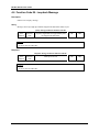
4.4 Function Code 05 - Force Single Digital Output
Description
Force a single digital output (0X reference) to either ON or OFF. These are the same digital outputs (DO)
used in Function Code 01.
The Modbus Comm Digital I/O Channel to address mapping is shown in Table 4-4.
The UMC800 does not support broadcast, and forcing can only be done in the Run mode.
Query
The query message specifies the DO to be forced. Registers are addressed starting at zero:
DO 1 is address 0.
The requested ON/OFF state is specified by a constant in the query data field.
A value of FF 00 hex requests it to be ON.
A value of 00 00 hex requests it to be OFF.
A value of FF FF releases the force.
ATTENTION: Any query (ON or OFF) causes a force mode of this point in the UMC800 controller. The
Green force LED goes ON. While in this mode, internal control of function blocks cannot communicate to
this point. DON’T FORGET to send a query to release this force.
Query message format for function code 05
Slave
Address
Function
Code
DO
Address
High
DO
Address
Low
Force
Data
High
Force
Data
Low
CRC
CRC
Example: Force DO Card Slot 1, Channel 6 ON in a slave at address 02.
02 05 00 05 FF 00 CRC CRC
Response
The normal response is an echo of the query, returned after the DO state has been forced.
Response message format for function code 05
Slave
Address
Function
Code
DO
Address
High
DO
Address
Low
Force
Data
High
Force
Data
Low
CRC
CRC
Example: Force DO Card Slot 1, Channel 6 ON in a slave at address 02.
02 05 00 05 FF 00 CRC CRC
Table 4-4 shows the Modbus Comm Digital I/O Channel to Address Mapping.
18
UMC800 Modbus® RTU Serial Communications User Manual
2/01
Modbus RTU Function Codes
4.5 Function Codes 06 - Preset Single Register
Description
Presets integer value into a single register (4X references).
The UMC800 does not support Broadcast.
The registers that are specified in Section 6 with an access type “W” and integer and bit packed data types,
can be written to via Function Code 06.
Query
The query message specifies the register references to be preset. Registers are addressed starting at zero:
Register 1 is addressed as 0.
Query message format for function code 06
Slave
Address
Function
Code
Address
High
Address
Low
Preset
Data
High
Preset
Data
Low
CRC
CRC
Example: Set Loop #1 to Auto (address 00FAh) to a slave at address 02.
02 06 00 FA 00 01 CRC CRC
Response
The normal response is an echo of the query returned after the register contents have been preset.
Response message format for function code 06
Slave
Address
Function
Code
Address
High
Address
Low
Preset
Data
High
Preset
Data
Low
CRC
CRC
Example: Set Loop #1 to Auto (address 00FAh) to a slave at address 02.
02 06 00 FA 00 01 CRC CRC
2/01
UMC800 Modbus® RTU Serial Communications User Manual
19
Modbus RTU Function Codes
4.6 Function Code 08 - Loopback Message
Description
Echoes received query message.
Query
Message can be any length up to half the length of the data buffer minus 8 bytes.
Query message format for function code 08
Slave
Address
Function
Code
Any data, length limited to approximately half
the length of the data buffer
CRC
CRC
CRC
CRC
Example:
02 08 01 02 03 04 CRC CRC
Response
Response message format for function code 08
Slave
Address
Function
Code
Data bytes received
Example:
02 08 01 02 03 04 CRC CRC
20
UMC800 Modbus® RTU Serial Communications User Manual
2/01
Modbus RTU Function Codes
4.7 Function Codes 16 (10h) - Preset Multiple Registers
Description
Presets values into a sequence of holding registers (4X references).
The UMC800 does not support Broadcast.
The register assignments specified in Section 6 with an access type “W”, can be written to via Function
Code 16 (10h).
Query
The query message specifies the register references to be preset. Registers are addressed starting at zero:
Register 1 is addressed as 0.
Query message format for function code 16 (10h)
Slave
Address
Function
Code
Starting
Address
High
Start
Address
Low
Number
Addresses
High
Number
Addresses
Low
Byte
Count
Data
CRC
CRC
Example: Preset Variable #1 (address 18C0h) to 100.0 from a slave at address 02.
02 10 18 C0 00 02 04 42 C8 00 00 CRC CRC
Response
The normal response returns the slave address, function code, starting address and the quantity of registers
preset.
The floating point values require two consecutive addresses. A request to preset a single floating point value
must be for two addresses. The byte order of the floating point number is determined by the setting of the
byte swap configuration value. In this example the byte swap order is FP B. Refer to subsection 3.3. The
first 16 bits of the response contain the IEEE MSB of the float value. The second 16 bits of the response
contain the IEEE LSB of the float value. The Byte order is configurable See Subsection 3.3. If the master
station requests only one address at an address of a floating point value the slave will respond with an
illegal data address exception (See Section 5) code.
Response message format for function code 16 (10h)
Slave
Address
Function
Code
Starting
Address
High
Start
Address
Low
Number
Addresses
High
Number
Addresses
Low
CRC
CRC
Example: Response from presetting Variable #1 (address 18C0h) to 100.0 from a slave at address 02.
02 10 18 C0 00 02 CRC CRC
2/01
UMC800 Modbus® RTU Serial Communications User Manual
21
Modbus RTU Function Codes
4.8 Function Code 17 (11h) - Report UMC800 ID
Description
Function code 17 (11h) is used to report the device information which includes information like: Slave ID,
device description, and firmware version.
Query
The query message specifies the function code only.
Query message format for function code 17 (11h)
Slave
Address
Function
Code
CRC
CRC
Example: Read Device ID from a slave at address 02.
02 11 CRC CRC
Response
The response is a record format describing the instrument.
Response message format for function code 17 (11h)
Slave
Address
Function
Code
Byte
Count
Slave
ID
Run
Indicator
Status
Device
Specific
Data
CRC
CRC
Slave ID - The Slave ID number for the UMC800 is 80 (hex)
(one byte) (byte 3)
Run Indicator Status:
(one byte) (byte 4)
00=OFF; FF=ON
Device Specific Data:
Device
Description
Model
ID
Device
Class
ID
Device
Mapping
Device Description:
(bytes 5-20)
16 Character ASCII Message with the following format:
‘U’
‘M’
‘C’
‘8’
‘0’
‘0’
‘‘
up to 9 character version number in
floating point notation.
zeros are appended for
the remaining bytes
For example:
A UMC800 with version number 3.22 would have the following device description:
‘U’
‘M’
‘C’
‘8’
‘0’
‘0’
‘‘
‘3’
‘.’
‘2’
‘2’
0
0
0
0
0
Model ID:
00 (one byte) (byte 21)
continued
22
UMC800 Modbus® RTU Serial Communications User Manual
2/01
Modbus RTU Function Codes
Device Class ID:
The Device Classification. (one byte) (byte 22)
Class ID
Class
00
Generic Class (Fixed Address Mapable)
01-FF
Future
Generic Class (00) Device Mapping:
Describes the I/O and feature mapping.
Number of
Records
Record
#1
Record
#2
Record
...
Record
#n
Number of Records:
1 Byte unsigned value 00-FFh (byte 23)
Record Description:
Byte
Description
00
Type of Data Element
(See Data Element Values Table Below)
01
Starting Address of Data Element Record (High)
02
Starting Address of Data Element Record (Low)
03
Number of Data Elements (High)
04
Number of Data Elements (Low)
Data Element Values Table:
Value
2/01
Description
00
Analog Inputs
01
Not Applicable. Number of elements equals 0.
02
Discrete Inputs
03
Discrete Outputs
04
Control Loops
05
Set Point Programmers
06
Variables
07
Not applicable. Number of elements equals 0.
08
Not applicable. Number of elements equals 0.
09
Not applicable. Number of elements equals 0.
10
Schedulers
11
Tagged Signals
UMC800 Modbus® RTU Serial Communications User Manual
23
Modbus RTU Exception Codes
5. Modbus RTU Exception Codes
Introduction
When a master device sends a query to a slave device it expects a normal response. One of four possible
events can occur from the master’s query:
•
Slave device receives the query without a communication error and can handle the query normally.
It returns a normal response.
•
Slave does not receive the query due to a communication error.
No response is returned. The master program will eventually process a time-out condition for the query.
•
Slave receives the query but detects a communication error (parity, LRC or CRC).
No response is returned. The master program will eventually process a time-out condition for the query.
•
Slave receives the query without a communication error but cannot handle it (i.e., request is to a nonexistent coil or register).
The slave will return with an exception response informing the master of the nature of the error (Illegal
Data Address.)
The exception response message has two fields that differentiate it from a normal response:
Function Code Field:
In a normal response, the slave echoes the function code of the original query in the function code field of
the response. All function codes have a most-significant bit (MSB) of 0 (their values are below 80 hex). In
an exception response, the slave sets the MSB of the function code to 1. This makes the function code value
in an exception response exactly 80 hex higher than the value would be for a normal response.
With the function code’s MSB set, the master’s application program can recognize the exception response
and can examine the data field for the exception code.
Data Field:
In a normal response, the slave may return data or statistics in the data field. In an exception response, the
slave returns an exception code in the data field. This defines the slave condition that caused the exception.
Query
Example: Internal slave error reading 2 registers starting at address 1820h from slave at slave address 02.
02 03 18 20 00 02 CRC CRC
Response
Example: Return MSB in Function Code byte set with Slave Device Failure (04) in the data field.
83 04 CRC CRC
24
UMC800 Modbus® RTU Serial Communications User Manual
2/01
Modbus RTU Exception Codes
Table 5-1 Modbus RTU Data Layer Status Exception Codes
Exception
Code
2/01
Definition
Description
01
Illegal Function
The message received is not an allowable action for the
addressed device.
02
Illegal Data Address
The address referenced in the function-dependent data
section of the message is not valid in the addressed
device.
03
Illegal Data Value
The value referenced at the addressed device location
is no within range.
04
Slave Device Failure
The addressed device has not been able to process a
valid message due to a bad device state.
06
Slave Device Busy
The addressed device has ejected a message due to a
busy state. Retry later.
07
NAK,
Negative Acknowledge
The addressed device cannot process the current
message. Issue a PROGRAM POLL to obtain devicedependent error data.
09
Buffer Overflow
The data to be returned for the requested number of
registers is greater than the available buffer space.
Function Code 20 only.
UMC800 Modbus® RTU Serial Communications User Manual
25
Register Map for Process and Operation Type Variables
6. Register Map for Process and
Operation Type Variables
What’s in this section?
This section describes all paramters accessible by Function Code 03, 04, 06 and 10h. Section 5.1 gives a
global overview of each function and its addresses/registers. Sections 5.2 through 5.17 contain the details
on each function and each of its parameters.
Your particular controller may not contain all parameters shown. If you see a function that is not on your
controller, either it is not available for that controller model or it is not in your configuration.
6.1 Register Map Overview
Table 6-1 describes the global register map for Function Code 03, 04, 06 and 10h. Details on each address
are in sections 6.2 through 6.17.
Conversion of Address (Hex) Number to Register (Decimal) Number
To convert the address number to the register number, convert the address from hexidecimal to decimal and
add 40001. Registers are addressed starting at zero: registers 1-16 are addressed as 0-15.
To convert the register number to the address number, subtract 40001 from the register and convert to hex.
Table 6-1 Global Register Map
Start Address
(hex)
0000
0040
0140
0240
0340
0440
0540
0640
0740
0840
0940
0A40
0B40
0C40
0D40
0E40
0F40
1800
18C0
1BE0
1E00
1E10
1E20
1E30
26
End Address
(hex)
< 0040
00FF
01FF
02FF
03FF
04FF
05FF
06FF
07FF
08FF
09FF
0AFF
0BFF
0CFF
0DFF
0EFF
0FFF
187F
19EB
1BE6
1E0F
1E1F
1E2F
1E3F
Description
Miscellaneous Parameters
Loop #1 (floating point & bit packed)
Loop #2 (floating point & bit packed)
Loop #3 (floating point & bit packed)
Loop #4 (floating point & bit packed)
Loop #5 (floating point & bit packed)
Loop #6 (floating point & bit packed)
Loop #7 (floating point & bit packed)
Loop #8 (floating point & bit packed)
Loop #9 (floating point & bit packed)
Loop #10 (floating point & bit packed)
Loop #11 (floating point & bit packed)
Loop #12 (floating point & bit packed)
Loop #13 (floating point & bit packed)
Loop #14 (floating point & bit packed)
Loop #15 (floating point & bit packed)
Loop #16 (floating point & bit packed)
Analog Input Value (#1-#64)
Variable Value (#1 - #150)
Time
Set Point Programmer #1
Set Point Programmer #2
Set Point Programmer #3
Set Point Programmer #4
UMC800 Modbus® RTU Serial Communications User Manual
See
Subsection
6.2
6.3
6.5
6.6
6.7
6.10
2/01
Register Map for Process and Operation Type Variables
Start Address
(hex)
1F00
1F40
1F80
1FC0
2000
2800
2A00
2C00
2E00
3000
3200
6600
6610
6620
6630
6640
6650
6660
6670
6680
6690
66A0
66B0
66C0
66D0
66E0
66F0
6B00
6B10
6B20
6B30
6B40
6B50
6B60
6B70
6B80
6B90
6BA0
6BB0
6BC0
6BD0
6BE0
6BF0
2/01
End Address
(hex)
1F3F
1F7F
1FBF
1FFF
27CF
29FF
2BFF
2DFF
2FFF
304F
3DFF
6606
6616
6626
6636
6646
6656
6666
6676
6686
6696
66A6
66B6
66C6
66D6
66E6
66F6
6B08
6B18
6B28
6B38
6B48
6B58
6B68
6B78
6B88
6B98
6BA8
6BB8
6BC8
6BD8
6BE8
6BF8
Description
Set Point Programmer #1 Additional Values
Set Point Programmer #2 Additional Values
Set Point Programmer #3 Additional Values
Set Point Programmer #4 Additional Values
Tagged Signal (#1 - #1000)
Set Point Programmer #1 Segments
Set Point Programmer #2 Segments
Set Point Programmer #3 Segments
Set Point Programmer #4 Segments
Scheduler #1 Value
Scheduler Segments
Hand Off Auto #1
Hand Off Auto #2
Hand Off Auto #3
Hand Off Auto #4
Hand Off Auto #5
Hand Off Auto #6
Hand Off Auto #7
Hand Off Auto #8
Hand Off Auto #9
Hand Off Auto #10
Hand Off Auto #11
Hand Off Auto #12
Hand Off Auto #13
Hand Off Auto #14
Hand Off Auto #15
Hand Off Auto #16
Device Control #1
Device Control #2
Device Control #3
Device Control #4
Device Control #5
Device Control #6
Device Control #7
Device Control #8
Device Control #9
Device Control #10
Device Control #11
Device Control #12
Device Control #13
Device Control #14
Device Control #15
Device Control #16
UMC800 Modbus® RTU Serial Communications User Manual
See
Subsection
6.12
6.9
6.13
6.15
6.16
6.18
6.19
27
Register Map for Process and Operation Type Variables
6.2 Miscellaneous Register Map
Table 6-2 Miscellaneous Register Map Addresses
Address
(hex)
Register
(decimal)
0000
40001
Parameter Name
Instrument Mode
Access
R/W
Notes
Bit Packed
Indicators:
Bit 0: 1:Diagnostic
Bit 1: 1: unused
Bit 2: 1:Maintenance/Offline mode
Bit 3: 1:Program mode
Bit 4: 1:Reset Unit/Force Cold Start
(Write Only)
Bit 5: 1:On-Line/Run mode
Bit 6…15: Unused
0002
40003
Load Recipe
R/W
Floating Point
Read: Returns zero
Write: Loads the recipe, identified in the
request, from the recipe pool.
28
UMC800 Modbus® RTU Serial Communications User Manual
2/01
Register Map for Process and Operation Type Variables
6.3 Loop Value Register Map
This table contains addresses of Loop #1; see Table 6-1for addresses of other loops. Each successive
control loop is offset by 256. The loop number corresponds to the PID block entry sequence during Control
Builder configuration. The Modbus loop number address for a loop can also be obtained from the Control
Builder printout of Tag Properties.
Function Code Support:
Reads – Function Codes 3/4
Writes – Function Code 16 (10 hex) for preset of multiple registers (e.g., for floating point )
Writes – Function Code 6 for presetting an integer value
Table 6-3 Loop Value Register Map Addresses
Address
(hex)
Register
(decimal)
Parameter Name
Access
Notes
0040
40065
PV
R
Floating Point in Engineering Units.
0042
40067
Remote Set Point; SP2
R/W
Floating Point in Engineering Units.
When the remote setpoint source is
configured as LSP2, the value can be
written.
0044
40069
Working Set Point
R/W
Floating Point in Engineering Units.
On a write to this register the instrument
will update the proper set point according
to the loop’s currently selected set point.
0046
40071
Output
R/W
Floating Point in Engineering Units.
0048
40073
PV
R
Floating Point in Engineering Units.
004A
40075
Carbon Potential block
temperature
R
Floating Point in Engineering Units
004C
40077
Gain #1 (Prop Band #1 if active)
R/W
Floating Point . (in units per what was
configured in the UMC800: Gain or
Proportional Band)
004E
40079
Direction
R
Floating Point
0.0=Direct; 1.0=Reverse
0050
40081
Reset #1
R/W
Floating Point in Repeats/Minute or
Minutes/Repeat.
0052
40083
Rate #1
R/W
Floating Point in Minutes
0054
40085
Cycle Time for Analog Scan
R
Floating Point in Seconds
0056
40087
PV Low Range
R
Floating Point in Engineering Units.
0058
40089
PV High Range
R
Floating Point in Engineering Units.
005A
40091
Alarm #1 SP #1
R/W
Floating Point in Engineering Units.
005C
40093
Alarm #1 SP #2
R/W
Floating Point in Engineering Units.
0060
40097
Gain #2 (Prop Band #2 if active)
R/W
Floating Point
2/01
UMC800 Modbus® RTU Serial Communications User Manual
29
Register Map for Process and Operation Type Variables
Address
(hex)
Register
(decimal)
Parameter Name
Access
Notes
0062
40099
Three Position Step Motor
Deadband
R/W
Floating Point in percent
0064
40101
Reset #2
R/W
Floating Point in Repeats/Minute or
Minutes/Repeat as configured in the
UMC800.
0066
40103
Rate #2
R/W
Floating Point in Minutes
0068
40105
Cycle Time for Analog Scan
R
Floating Point in Seconds
006A
40107
LSP #1
R/W
Floating Point in Engineering Units
006C
40109
LSP #2
R/W
Floating Point in Engineering Units.
006E
40111
Alarm #2 SP #1
R/W
Floating Point in Engineering Units.
0070
40113
Alarm #2 SP #2
R/W
Floating Point in Engineering Units.
0074
40117
SP Low Limit
R/W
Floating Point in Engineering Units.
Operator Limit
0076
40119
SP High Limit
R/W
Floating Point in Engineering Units.
Operator Limit
0078
40121
Working Set Point
R/W
Floating Point in Engineering Units.
On a write to this register the instrument
will update the proper set point according
to the loop’s currently selected set point.
007A
40123
Output Low Limit
R/W
Floating Point in Engineering Units.
007C
40125
Output High Limit
R/W
Floating Point in Engineering Units.
007E
40127
Output Working Value
R/W
Floating Point in Engineering Units.
0088
40137
Bias
R/W
Floating Point in Engineering Units.
Auto/Man bias block, value is Read-Only
008A
40139
Deviation
R
Floating Point in Engineering Units.
(SP-PV)
008E
40143
Manual Reset
R/W
Floating Point in Engineering Units.
0090
40145
Feed-forward Gain
R/W
Floating Point in Engineering Units.
0092
40147
Local Percent Carbon Monoxide
R/W
Floating Point in Engineering Units.
0094
40149
Furnace Factor
R/W
Floating Point in Engineering Units.
0096
40151
Percent Hydrogen
R/W
Floating Point in Engineering Units.
0098
40153
On/Off Output Hysterisis
R/W
Floating Point in percent of input span
009A
40155
Carbon Potential Dewpoint
R/W
Floating Point in Engineering Units
009C
40157
Three Position Step Motor Time
R/W
Floating Point in seconds
00F7
40248
Enable/Disable Fuzzy
R/W
Bit Packed
Bit 0: 0:Disable; 1:Enable
30
UMC800 Modbus® RTU Serial Communications User Manual
2/01
Register Map for Process and Operation Type Variables
Address
(hex)
Register
(decimal)
Parameter Name
Access
Notes
00F8
40249
Demand Tune Request
R/W
Bit Packed (one shot action, activates
autotuning until autotuning completed)
Bit 0: 0:Off; 1:On
Bit 1-15: Unused
00F9
40250
Anti-soot set point limit enable
R/W
Bit Packed
Bit 0: 0:Off; 1:On
Bit 1-15: Unused
00FA
40251
Auto/Manual State
R/W
Bit Packed
Bit 0: 0:Manual; 1:Auto
Bit 1-15: Unused
00FB
40252
Set Point State
R/W
Bit Packed (selects either SP1 or SP2 as a
local SP if the UMC800 is configured as
such in PID setup)
Bit 0: 0:SP1; 1:SP2
Bit 1-15: Unused
00FC
40253
Remote/Local Set Point State
R/W
Bit Packed
Bit 0: 0:LSP; 1:RSP
Bit 1-15: Unused
00FD
40254
Tune Set State
R/W
Bit Packed (selects tuning constant set)
Bit 0: 0:Tune Set #1; 1:Tune Set #2
Bit 1-15: Unused
00FE
40255
Loop Status
R
Bit Packed
Bit 0: Mode: 0:Manual; 1:Auto
Bit 1: Set Point: 0:SP1; 1:SP2
Bit 2: Remote/Local: 0:LSP; 1:RSP
Bit 3: Tune Set: 0:Set #1; 1:Set #2
Bit 4: IMAN: 0:Inactive; 1:Active
Bit 5: LO: 0: Inactive; 1:Active
Bit 6-15: Reserved
2/01
UMC800 Modbus® RTU Serial Communications User Manual
31
Register Map for Process and Operation Type Variables
6.4 Example for queries using Function Codes 3, 6, 16
Example 1
Query: Read PV, Remote SP, Working SP, Output for Loop 1 from UMC800 at address 2 using Function Code 3
(hex codes). This will be accomplished by accessing contiguous registers.
02
03
00
40
00
08
CRC
CRC
Response: where PV=1000.0, Remote SP=1000.0, Working SP=1000.0, Output=50.0
02
03
10
44
7A
00
00
44
7A
00
00
44
7A
00
00
42
48
00
00
CRC
CRC
Example 2:
Query: Write a Local Setpoint , (address 006A) to 100.0 for loop 1 at UMC 800 address 1 using Function Code
16 (10 hex). Function code 16 is used for presetting multiple registers. Registers are addressed starting
at zero: Register 1 is addressed as 0.
01
10
00
6A
00
02
04
42
C8
00
00
CRC
CRC
Response: from preset of LSP#1, address 006A to 100.0 at address 1.
01
10
00
6A
00
02
CRC
CRC
Example 3:
Query: Set Loop #1 to Auto (register 00FA hex) at controller address 1. This is a bit-packed single register data
type. Registers are addressed starting at 0: Register 1 is addressed as 0.
01
06
00
FA
00
01
CRC
CRC
Response: from preset of LSP#1, address 006A to 100.0 at address 1.
01
32
06
00
FA
00
01
CRC
CRC
UMC800 Modbus® RTU Serial Communications User Manual
2/01
Register Map for Process and Operation Type Variables
6.5 Analog Input, Frequency Input, Pulse Input Value Register Map
Summary
Used to access analog input, frequency input, or pulse input parameters.
Analog Input Example: AI1 through AI64. The mapping is with respect to card position starting with the
first card slot position (numbered 1 through 16, starting at the lower left) with an analog input card. Since
each card has 4 inputs, the first card position with analog inputs (I/O card Type 1) would be AI1 thru AI4.
As an example, if the first AI card is in the Slot 1, this would represent AI1 through AI4. If the next AI
card is in slot 2 this would be AI5 thru AI 8 and so on.
The Frequency Inputs and Pulse Inputs map the same as the Analog Inputs..
Function Code Support:
Reads – Function Codes 3 and 4
Table 6-4 Analog Input, Frequency Input, Pulse Input Value Register Map Addresses
Address
(hex)
1800
1802
1804
1806
1808
180A
180C
180E
1810
1812
1814
1816
:
187E
Register
(decimal)
46145
46147
46149
46151
46153
46155
46157
46159
46161
46163
46165
46167
:
46271
Channel Number
Access
Analog Input, Frequency Input, or Pulse Input #1
Analog Input, Frequency Input, or Pulse Input #2
Analog Input, Frequency Input, or Pulse Input #3
Analog Input, Frequency Input, or Pulse Input #4
Analog Input, Frequency Input, or Pulse Input #5
Analog Input, Frequency Input, or Pulse Input #6
Analog Input, Frequency Input, or Pulse Input #7
Analog Input, Frequency Input, or Pulse Input #8
Analog Input, Frequency Input, or Pulse Input #9
Analog Input, Frequency Input, or Pulse Input #10
Analog Input, Frequency Input, or Pulse Input #11
Analog Input, Frequency Input, or Pulse Input #12
:
Analog Input, Frequency Input, or Pulse Input #64
R
R
R
R
R
R
R
R
R
R
R
R
Notes
Floating Point
in Engineering
Units.
R
Example
Read Analog Inputs 1 and 2 from UMC800 at address 2 using Function Code 3.
02
03
18
00
00
04
CRC
CRC
Response from UMC800 where AI1 = 100.0 and AI 2 = 55.32
02
2/01
03
08
42
C8
00
00
42
5D
47
UMC800 Modbus® RTU Serial Communications User Manual
AE CRC CRC
33
Register Map for Process and Operation Type Variables
6.6 Variable Register Map
Summary
Variables (analog or digital) are writeable parameters in UMC 800 attached to input pins of function blocks.
Digital Variable status is 0.0 for OFF or logic 0 and 1.0 for ON or logic 1. The Variable number in the table
corresponds to the Variable number in the UMC 800 configuration. You will need to access the UMC 800
Control Builder configuration or corresponding configuration printout of Tag Properties to identify the
Variable numbers desired.
Function Code Support:
Read – Function Code 3
Write – Function Code 16 (10 Hex)
Table 6-5 Variable Register Map Addresses
Address
(hex)
Register
(decimal)
18C0
46337
Variable Value #1
R/W
18C2
46339
Variable Value #2
R/W
18C4
46341
Variable Value #3
R/W
18C6
46343
Variable Value #4
R/W
:
18C8
46345
Variable Value #5
R/W
:
18CA
46347
Variable Value #6
R/W
:
18CC
46349
Variable Value #7
R/W
:
18CE
46351
Variable Value #8
R/W
:
18D0
46353
Variable Value #9
R/W
:
18D2
46355
Variable Value #10
R/W
:
18D4
46357
Variable Value #11
R/W
:
18D6
46359
Variable Value #12
R/W
:
18D8
46361
Variable Value #13
R/W
:
18DA
46363
Variable Value #14
R/W
:
18DC
46365
Variable Value #15
R/W
:
18DE
46367
Variable Value #16
R/W
:
18E0
46369
Variable Value #17
R/W
:
18E2
46371
Variable Value #18
R/W
:
18E4
46373
Variable Value #19
R/W
:
18E6
46375
Variable Value #20
R/W
:
:
:
1ABE
46847
Channel Number
Access
Notes
Floating Point in Engineering Units.
:
Variable Value #150
:
R/W
:
continued
34
UMC800 Modbus® RTU Serial Communications User Manual
2/01
Register Map for Process and Operation Type Variables
Example
Query: Read Variables 1 and 2 from UMC800 at address 1 using Function Code 3 (hex codes).
01
03
18
C0
00
04
CRC
CRC
Response: from UMC800 where Variable 1 = 100.0 and Variable 2 = 55.32
01
03
08
42
C8
00
00
42
5D
47
AE
CRC CRC
6.7 Time Register Map
Table 6-6 Time Register Map Addresses
Address
(hex)
Register
(decimal)
Channel Number
Access
Notes
1BE0
47137
Hours
R/W
0 to 23
1BE1
47138
Minutes
R/W
0 to 60
1BE2
47139
Seconds
R/W
0 to 60
1BE3
47140
Month
R/W
1 to 12
1BE4
47141
Day
R/W
1 to 31
1BE5
47142
Year
R/W
1970 to 2037
The values read are always in the range
of 1970 to 2037 for a write. 0 – 37
represents 2000 – 2037, 70 – 99
represents 1970 – 1999
1BE6
47143
Week Day
R
0 to 6 (0 = Sunday)
ATTENTION
Clock registers must be written in a single transaction. They can be written in one transaction of registers 47137
through 47142 or one transaction of registers 47137 through 47143.
2/01
UMC800 Modbus® RTU Serial Communications User Manual
35
Register Map for Process and Operation Type Variables
6.8 Alarm Status Register Map
Summary
The alarm status number is mapped to the position of the alarm in the Alarm Display Tag Group, which is
assigned with the Control Builder configuration tool, starting with Group 1 up through Group 10. Group 1
applies to the first 12 alarms which are numbered starting at the top left position of the display (Alarm 1)
through to the bottom right position (Alarm 12). Successive groups define alarms 13 through 120.
Table 6-7 Alarm Status Register Map Addresses
Address
(hex)
Register
(decimal)
1BF0
47153
Alarm Status #1 - #16
R
1BF1
47154
Alarm Status #17 - #32
R
1BF2
47155
Alarm Status #33 - #48
R
1BF3
1BF4
1BF5
1BF6
1BF7
47156
47157
47158
47159
47160
Alarm Status #49 - #64
Alarm Status #65 - #80
Alarm Status #81 - #96
Alarm Status #97 - #112
Alarm Status #113 - #120
R
R
R
R
R
36
Channel Number
Access
Notes
Bit Packed
Bit 0: Alarm #1 Status
Bit 1: Alarm #2 Status
:
Bit 15: Alarm #16 Status
0: Alarm OFF
1: Alarm ON
Bit Packed
Bit 0: Alarm #17 Status
Bit 1: Alarm #18 Status
:
Bit 15: Alarm #32 Status
0: Alarm OFF
1: Alarm ON
Bit Packed
Bit 0: Alarm #33 Status
Bit 1: Alarm #34 Status
:
Bit 15: Alarm #48 Status
0: Alarm OFF
1: Alarm ON
:
:
:
:
Bit Packed
Bit 0: Alarm #113 Status
Bit 1: Alarm #114 Status
Bit 2: Alarm #115 Status
Bit 3: Alarm #116 Status
Bit 4: Alarm #117 Status
Bit 5: Alarm #118 Status
Bit 6: Alarm #119 Status
Bit 7: Alarm #120 Status
Bits 8-15: Unused
0: Alarm OFF
1: Alarm ON
UMC800 Modbus® RTU Serial Communications User Manual
2/01
Register Map for Process and Operation Type Variables
6.9 Signal Tag Register Map
Summary
Signal tags are connected to output pins of function blocks, representing analog or digital parameters, and
are read-only parameters. The signal tag number in the table corresponds to the signal tag number in the
UMC 800 Control Builder configuration. You will need to access the Control Builder configuration Tag
Properties printout to identify the Signal Tag numbers desired. The Modbus address is also supplied in this
printout for each signal tag.
Function Code Support:
Read – Function Code 3
Table 6-8 Signal Tag Register Map Addresses
Address
(hex)
Register
(decimal)
Channel Number
Access
2000
48193
Tagged Signal #1
R
Floating Point in Engineering Units
2002
48195
Tagged Signal #2
R
2004
48197
Tagged Signal #3
R
NOTE: Digital Signal Tags are
represented as 0.0 for OFF, 1.0 for ON.
2006
48199
Tagged Signal #4
R
2008
48201
Tagged Signal #5
R
200A
48203
Tagged Signal #6
R
200C
48205
Tagged Signal #7
R
200E
48207
Tagged Signal #8
R
2010
48209
Tagged Signal #9
R
2012
48211
Tagged Signal #10
R
:
2014
48213
Tagged Signal #11
R
:
2016
48215
Tagged Signal #12
R
:
2018
48217
Tagged Signal #13
R
:
201A
48219
Tagged Signal #14
R
:
201C
48221
Tagged Signal #15
R
:
201E
48223
Tagged Signal #16
R
:
:
:
:
:
27CE
50191
R
:
:
Tagged Signal #500
Notes
:
:
:
:
:
:
:
Example
Query: Read Signal Tags 3 and 4 from UMC800 at address 1 using Function Code 3 (hex codes).
01
03
20
04
00
04
CRC
CRC
Response: from UMC800 where Signal Tag 3 = 100.0 and Signal Tag 4 = 55.32
01
2/01
03
08
42
C8
00
00
42
5D
47
UMC800 Modbus® RTU Serial Communications User Manual
AE
CRC CRC
37
Register Map for Process and Operation Type Variables
6.10 Set Point Program Register Maps
Summary
The SP Programmer parameters are listed according to category related to program status and interaction, other
programmer parameters and program segment mapping. A section is also provided to aid in configuring a SP
programmer and recipe interface for third party software.
Function Code Support:
Read – Function Code 3
Write – Function Code 16 (10 Hex)
Considerations and Methods for Downloading. Operating, and Reading Status of SP Programs:
A SP programmer interface can be developed (and recipes containing a SP profile can be created) in third
party software using the parameters listed in the following table.
In creating a SP Programmer interface showing a number of segments, a graphic display might include a
table referencing the maximum number of ramp/soak segments that you will be using for your process. The
parameters to be referenced for each segment are listed in Table 6-15 - Register Map (Ramp/Soak
Segments).
Programmer Numbers
The parameters that follow refer to SP Programmer 1. The offsets (starting addresses) for SP Programmers
2, 3 and 4 are 10 (hex) or 16 decimal:
38
Programmer Number
Starting
Address
(Hex)
Ending
Address
(Hex)
SP Programmer 1
1E00
1E0F
SP Programmer 2
1E10
1E1F
SP Programmer 3
1E20
1E2F
SP Programmer 4
1E30
1E3F
UMC800 Modbus® RTU Serial Communications User Manual
2/01
Register Map for Process and Operation Type Variables
Controlling the Program
For controlling the program, the following parameters should be accessed:
Parameter
Addr (Hex)
Notes
SP Programmer Output
1E00
See Table 6-12
Current Segment Number
1E02
See Table 6-12
Program Elapsed Time
1E04
See Table 6-12
Segment Time Remaining
1E08
See Table 6-12
Current Segment Events
1E0A
See Table 6-12
Status
1E0B
See Table 6-12
Start (write only)
1E0C
See Table 6-12
Hold (write only)
1E0D
See Table 6-12
Advance (write only)
1E0E
See Table 6-12
Reset (write only)
1E0F
See Table 6-12
Current Program Number
1F00
See Table 6-13
Auxiliary Output
1F04
See Table 6-13
Parameters for the Profile
You will also need to define the following for the parameters for the profile:
Parameter
2/01
Addr (Hex)
Notes
Time Units
1F3A
See Table 6-13
Ramp Units (segments)
1F3B
See Table 6-13
Guaranteed Soak Type
1F3C
See Table 6-13
Guaranteed Soak Low
1F06
See Table 6-13
Guaranteed Soak High
1F08
See Table 6-13
Prog Save Request
1F02
See Table 6-13
UMC800 Modbus® RTU Serial Communications User Manual
39
Register Map for Process and Operation Type Variables
Procedures for Downloading Setpoint Programs
These steps are for programmer 1. For programmers 2, 3, and 4, adjust the register addresses accordingly.
Table 6-9 is for downloading using Function Codes 3, 4, 6, 16.
Table 6-10 is for downloading using Function Codes 20 and 21.
Table 6-9 Steps to Download a Setpoint Program using Modbus Function Codes 3, 4, 6, 16
Step
Action
1
Set the programmer to RESET by writing any number to 47696 (1E0F). This can be done
either with function code 6 or 16.
2
Clear the program by writing a 0 to registers 47937 and 47938 (1F00 and 1F01). This is a
floating point register and requires a multiple register write (function code 16). This is the
safest way to insure that all registers are cleared for the next program download.
3
Write the header information for parameters relevant to the program (leave all others at 0) -registers 47943 (1F06) - 47997 (1F3C). Registers 47943 - 47968 are floats and must be
written using function code 16. Registers 47995 - 47997 are bit-packed and can be written
with either function code 6 or 16.
Note: Display High Range Limit and Display Low Range Limit are not presently used in the
UMC800.
4
Write the information for each segment required in the profile -- registers 2800 - 2807 for
segment 1, 2808 - 280F for segment 2, etc. The first 2 registers are bit-packed and can be
written with either function code 6 or 10. The rest of the registers are float and must be
written using function code 16.
5
Save the program to a program (profile) number archive by writing a floating point number to
register 47939. This will store the downloaded data utilized by the programmer block to the
program (profile) number used. Profile numbers may range from 1-70.
The program is now ready to run. Note that the current program (profile) number -- register 47937 -is automatically set to the saved program number.
40
UMC800 Modbus® RTU Serial Communications User Manual
2/01
Register Map for Process and Operation Type Variables
Table 6-10 Steps to Download a Setpoint Program using Modbus Function Codes 20, 21
Step
Action
1
Set the programmer to RESET by writing any number to 47696 (1E0F). This can be done
either with function code 6 or 16. (could use a function code 21 scattered write, but this
requires knowledge of the SPP block number in the configuration)
2
Clear the program by writing a 0 to registers 47937 and 47938 (1F00 and 1F01). This is a
floating point register and requires a multiple register write (function code 16). This is the
safest way to insure that all registers are cleared for the next program download.
(could use a function code 21 scattered write, but this requires knowledge of the SPP block
number in the configuration)
3
Write the header information for parameters relevant to the program (leave all others at 0) -registers 47943 (1F06) - 47997 (1F3C). Registers 47943 - 47968 are floats and must be
written using function code 16. Registers 47995 - 47997 are bit-packed and can be written
with either function code 6 or 16. (could use a function code 21 scattered write, but this
requires knowledge of the SPP block number in the configuration)
Note: Display High Range Limit and Display Low Range Limit are not presently used in the
UMC800.
4
Use function code 21 to write each segment required in the profile. See Section 7.
5
Save the program to a program (profile) number archive by writing a floating point number to
register 47939. This will store the downloaded data utilized by the programmer block to the
program (profile) number used. Profile numbers may range from 1-70. (could use a function
code 21 scattered write, but this requires knowledge of the SPP block number in the
configuration)
The program is now ready to run. Note that the current program (profile) number -- register 47937 -is automatically set to the saved program number.
Procedure for Uploading Setpoint Programs
Table 6-11 Steps to Upload a Setpoint Program using Modbus Function Codes 3, 4, 6, 16
Step
2/01
Action
1
Set the programmer to RESET by writing any number to 47696 (1E0F). This can be done
either with function code 6 or 16.
2
Load the program into the setpoint programmer block by writing the program number to
registers 47937 and 47938 (1F00 and 1F01). This is a floating point register and requires a
multiple register write (function code 16).
3
Read the header information desired -- registers 47043 (1F06) - 47997 (1F3C) using
function code 3 or 4.
4
Read the information for each segment desired using function code 3 or 4 — registers 2800
- 2807 for segment 1, 2808 - 280F for segment 2, etc.
UMC800 Modbus® RTU Serial Communications User Manual
41
Register Map for Process and Operation Type Variables
6.11 Set Point Programmer Value Register Map
Table 6-12 Set Point Programmer Value Register Map Addresses
Address
(hex)
Register
(decimal)
1E00
1E02
47681
47683
Set Point Programmer Output
Current Segment Number
R
R/W
1E04
47685
Program Elapsed Time
R
1E08
1E0A
47689
47691
Segment Time Remaining
Current Segment Events
R
R
1E0B
47692
Status
R
1E0C
47693
Run
W
1E0D
47694
Hold
W
1E0E
47695
Advance
W
1E0F
47696
Reset
W
42
Channel Number
Access
Notes
Floating Point in Engineering Units.
Floating Point; 1...Max Segment # 50
A write changes the segment number.
Floating Point in Minutes
Continues to run when in Hold
Floating Point in Minutes
Bit Packed
Indicates status of events 1-16 in one register
Bit 0: Event #1
:
Bit 15: Event #16
0: Event OFF 1: Event ON
Bit Packed
Bit 0: 1=Ready
1: 1=Run
2: 1=Hold
3: 1=End
4: 1=Reserved
5: 1=Time Units in Minutes
6: 1=Time Units in Hours
7: Ramp Units
0: Time 1: Rate
8: Reserved
9: If bit 2 Set
0: Operator hold
1: Guaranteed soak hold
10: 0: Current segment is a soak
1: Current segment is a ramp
11-15: Reserved
Signed 16 bit integer
Write to location Starts Profile;
Data ignored
Signed 16 bit integer
Write to location Holds Profile;
Data ignored
Signed 16 bit integer
Write to location Advances Profile one
segment while in Hold mode;
Data ignored
Signed 16 bit integer
Write to location Resets Profile after program
is first in Hold mode;
Data ignored
UMC800 Modbus® RTU Serial Communications User Manual
2/01
Register Map for Process and Operation Type Variables
6.12 Set Point Programmer Additional Values Register Map
Table 6-13 Set Point Programmer Additional Values Register Map Addresses
Address
(hex)
Register
(decimal)
1F00
47937
Channel Number
Current Program Number
Access
R/W
Notes
Floating Point
This is optional, indicates present profile
number in use. This also allows entry of a
profile number from the UMC800 stored
profile memory (if profiles have been
stored in the controller) and will retrieve
the profile data for a display showing a
SP profile segment table. Typically, when
recipes are downloaded from third party
software, this will be the number
generated by the Program Save Request
parameter
A write to this register loads the program
into the set point programmer function
block; if 0 is written, the function block’s
program is cleared.
Notes 2
1F02
47939
Program Save Request
R/W
Floating Point
Assigns profile parameters downloaded to
a profile number such as 1. This is
required by the UMC800 to be the last
parameter downloaded. This overwrites
what is in this UMC800 SP Profile
memory location on each download of a
new SP profile.
Saves the program into the archive.
Writing to this register is prohibited in the
run mode.
1F04
47941
Auxiliary Output
R
Floating Point
1F06
47943
Guaranteed Soak Low
R/W
Floating Point
Presets High Deviation setting in engr
units.
Writing to this register is only
permissible in the reset or ready mode
1F08
47945
Guaranteed Soak High
R/W
Floating Point
Presets Low Deviation setting in engr
units.
Writing to this register is only
permissible in the reset or ready mode
1F0A
47947
Restart Ramp Rate
R/W
Floating Point
Writing to this register is only
permissible in the reset or ready mode
1F0C
47949
Display High Range Limit
R/W
Floating Point
Writing to this register is only
permissible in the reset or ready mode
1F0E
47951
Display Low Range Limit
R/W
Floating Point
Writing to this register is only
permissible in the reset or ready mode
2/01
UMC800 Modbus® RTU Serial Communications User Manual
43
Register Map for Process and Operation Type Variables
Address
(hex)
Register
(decimal)
Channel Number
Access
Notes
1F10
47953
Jog Segment
R/W
Floating Point
Writing to this register is only
permissible in the reset or ready mode
1F12
47955
Loop Start
R/W
Floating Point
0 indicates no loop.
Writing to this register is only
permissible in the reset or ready mode
1F14
47957
Loop End
R/W
Floating Point
0 indicates no loop.
Writing to this register is only
permissible in the reset or ready mode
1F16
47959
Repeats
R/W
Floating Point
0 indicates loop forever.
Writing to this register is only
permissible in the reset or ready mode
1F3A
47995
Time Units
R/W
Bit Packed
Bit 0: Reserved
1: minutes
2: hours
3-15: Unused
1F3B
47996
Ramp Units
R/W
Bit Packed
Bit 0: 0:Time; 1:Rate
Bit 1-15: Unused
Writing to this register is only
permissible in the reset or ready mode
1F3C
47997
Guaranteed Soak Type
R/W
Bit Packed
For selection of Soak (or Hold) guarantee
– Per Segment (requiring selection per
segment in a table)
Bit 0: per segment
1: all soaks
2: all segments
3-15: Unused
None if none of the bits is set
Writing to this register is only
permissible in the reset or ready mode
44
UMC800 Modbus® RTU Serial Communications User Manual
2/01
Register Map for Process and Operation Type Variables
6.13 Set Point Programmer Segment Map
A profile contains up to 50 segments. Each segment is made up of 8 registers. The segment mapping for
setpoint programmer #1 is shown below.
Table 6-14 Set Point Programmer Segment Map Addresses
Start Address
End Address
Description
2800
2807
Set Point Programmer #1 Segment 1
2808
280F
Set Point Programmer #1 Segment 2
2810
2817
Set Point Programmer #1 Segment 3
:
:
:
2988
298F
Set Point Programmer #1 Segment 50
6.14 Segment Register Map
The table below describes the registers that are part of a setpoint programmer segment. To determine the
actual register address for a parameter within a segment, add the register offset to the start address of the
segment.
Table 6-15 Segment Register Map Addresses
Register
Offset within
Segment
0
Parameter Name
Ramp/Soak Segment
Access
R/W
Guaranteed Soak
Enable
1
Events
R/W
2
Time or Rate
R/W
4
Ramp or Soak value
R/W
6
Soak value for
auxiliary output (use
“Time or Rate” for
duration)
R/W
2/01
Notes
Bit Packed
Bit 0: 1 = ramp segment; 0=soak segment
Bit 1: 1 = guaranteed soak enabled
0 = guaranteed soak disabled
Bit 0 is ignored in the hold mode.
Writing to this register is not permissible in the run mode.
Bit Packed
Bit 0: Event #1
:
:
Bit 15: Event #16
0: Event OFF 1: Event ON
Writing to this register is only permissible in reset or ready
mode.
Floating Point in time units configured for the set point
programmer
Writing to this register is not permissible in the run mode.
Floating Point
Writing to this register is not permissible in the run mode.
Floating Point
Writing to this register is not permissible in the run mode.
UMC800 Modbus® RTU Serial Communications User Manual
45
Register Map for Process and Operation Type Variables
6.14.1 Example For Determining a Segment Register
To change the ramp value in segment #8 of setpoint programmer #2, the register address is determined as
follows.
Step 1: Use Table 6-1 to determine the start address for setpoint program #2 profile. The value is 2A00
Hex.
Step 2: Calculate the offset address for segment 8 in a profile. This is calculated as:
Segment #8 offset address
=
(segment number – 1) * 8
=
(8-1) * 8
=
56 or 38 Hex
Step 3: Use the table above to determine the register offset for the ramp value. The value is 4.
Step 4: Calculate the address by adding the results of steps 1, 2, and 3 to determine the register address.
Register address
46
=
Setpoint program #2 profile base address
+ Segment 8 offset address
+ Ramp value register offset
=
2A00 + 38 + 4
=
2A3C
UMC800 Modbus® RTU Serial Communications User Manual
2/01
Register Map for Process and Operation Type Variables
6.15 Scheduler Value Register Map
Summary
The SP Scheduler parameters are listed according to category related to SP Scheduler status plus interaction
and scheduler segment mapping. A section is also provided to aid in configuring a Scheduler and recipe
interface for third party software.
Function Code Support
Read – Function Code 3
Write – Function Code 16 (10 hex)
Scheduler Value Register Map
You will need to define the parameters for the Schedule as required by the application. Application notes
for these parameters are provided and further defined in the Scheduler Value Register Map Table 6-19.
Scheduler Segment Register Map
Table 6-20 indicates the range of addresses applicable to a scheduler segment. Each segment uses 48
registers (30 hex).
Segment Register Map Addresses
Table 6-21 describes the registers that are part of a schedule segment. To determine the actual register
address for a parameter within a segment, add the register offset to the start address of the segment.
Considerations and Methods for Downloading, Operating, and Reading Status of SP Schedules
A SP Scheduler interface can be developed (and recipes containing a schedule can be created) in third party
software using the parameters listed in Table 6-21.
In creating a Scheduler interface showing a number of segments and outputs for each segment on a graphic
display might include a table referencing the maximum number of segments that you will be using for your
process. Refer to the Scheduler Segment Register Map - Table 6-20 for the range of addresses applied to
each scheduler segment. Each segment uses 48 registers (30 hex). Use the Segment Register Map - Table
6-21 for the parameters to be referenced for read/write within each segment. Application notes for these
segment parameters is provided.
2/01
UMC800 Modbus® RTU Serial Communications User Manual
47
Register Map for Process and Operation Type Variables
Procedures for Downloading Setpoint Schedules
Table 6-16 is for downloading using Function Codes 3, 4, 6, 16.
Table 6-17 is for downloading using Function Codes 20 and 21.
Table 6-16 Steps to Download a Setpoint Schedule using Modbus Function Codes 3, 4, 6, 16
Step
Action
1
Set the scheduler to RESET by writing any number to 52367 (304E). This can be done either
with function code 6 or 16.
2
Clear the schedule by writing a 0 to registers 52321 and 52322 (3020 and 3021). This is a
floating point register and requires a multiple register write (function code 16). This is the
safest way to insure that all registers are cleared for the next schedule download.
3
Write the header information for parameters relevant to the schedule (leave all others at 0) -registers 52331 (302A) - 52347 (303A) and register 52368 (304F). Registers 52331 - 52347
are floats and must be written using function code 16. Register 52368 is bit-packed and can
be written with either function code 6 or 16.
4
Write the information for each segment required in the schedule -- registers 3200 – 322F for
segment 1, 3230 – 325F for segment 2, etc. The first 9 registers are bit-packed and can be
written with either function code 6 or 10. The rest of the registers are float and must be
written using function code 16.
5
Save the schedule to a schedule number archive by writing a floating point number to
register 52329. This will store the downloaded data utilized by the scheduler block to the
schedule number used. Schedule numbers may range from 1-50.
The schedule is now ready to run. Note that the current schedule number -- register 52321-- is
automatically set to the saved schedule number.
48
UMC800 Modbus® RTU Serial Communications User Manual
2/01
Register Map for Process and Operation Type Variables
Table 6-17 Steps to Download a Setpoint Schedule using Modbus Function Codes 20, 21
Step
Action
1
Set the scheduler to RESET by writing any number to 52367 (304E). This can be done either
with function code 6 or 16. (could use a function code 21 scattered write, but this requires
knowledge of the SPP block number in the configuration)
2
Clear the schedule by writing a 0 to registers 52321 and 52322 (3020 and 3021). This is a
floating point register and requires a multiple register write (function code 16). This is the
safest way to insure that all registers are cleared for the next schedule download. (could use
a function code 21 scattered write, but this requires knowledge of the SPP block number in
the configuration)
3
Write the header information for parameters relevant to the schedule (leave all others at 0) -registers 52331 (302A) - 52347 (303A) and register 52368 (304F). Registers 52331 - 52347
are floats and must be written using function code 16. Register 52368 is bit-packed and can
be written with either function code 6 or 16. (could use a function code 21 scattered write,
but this requires knowledge of the SPP block number in the configuration)
4
Use function code 21 to write each segment required in the profile. See Section 7.
5
Save the schedule to a schedule number archive by writing a floating point number to
register 52329. This will store the downloaded data utilized by the scheduler block to the
schedule number used. Schedule numbers may range from 1-50. (Could use a function
code 21 scattered write, but this requires knowledge of the SPP block number in the
configuration).
Procedure for Uploading Setpoint Schedules
Table 6-18 Steps to Upload a Setpoint Schedule using Modbus Function Codes 3, 4, 6, 16
Step
Action
1
Set the scheduler to RESET by writing any number to 52367 (304E). This can be done either
with function code 6 or 16.
2
Load the schedule into the setpoint scheduler block by writing the schedule number to
registers 52321 and 52322 (3020 and 3021). This is a floating point register and requires a
multiple register write (function code 16)
3
Read the header information desired -- registers 52331 (302A) - 52347 (303A) and register
52368 (304F) using function code 3 or 4.
4
Read the information for each segment desired using function code 3 or 4 -- registers 3200 322F for segment 1, 3230 - 325F for segment 2, etc.
2/01
UMC800 Modbus® RTU Serial Communications User Manual
49
Register Map for Process and Operation Type Variables
Table 6-19 Scheduler Value Register Map Addresses
Address
(hex)
Register
(decimal)
3000
3002
3004
3006
3008
300A
300C
300E
3010
3012
3014
3016
3018
301A
301C
301E
3020
52289
52291
52293
52295
52297
52299
52301
52303
52305
52307
52309
52311
52313
52315
52317
52319
52321
Scheduler Output 1
Scheduler Output 2
Scheduler Output 3
Scheduler Output 4
Scheduler Output 5
Scheduler Output 6
Scheduler Output 7
Scheduler Output 8
Scheduler Auxiliary Output 1
Scheduler Auxiliary Output 2
Scheduler Auxiliary Output 3
Scheduler Auxiliary Output 4
Scheduler Auxiliary Output 5
Scheduler Auxiliary Output 6
Scheduler Auxiliary Output 7
Scheduler Auxiliary Output 8
Current Program Number
R
R
R
R
R
R
R
R
R
R
R
R
R
R
R
R
R/W
3022
52323
Current Segment Number
R/W
3024
52325
Program Elapsed Time
R
3026
52327
Segment Time Remaining
R
50
Channel Number
Access
Notes
Floating Point in Engineering Units.
Floating Point in Engineering Units.
Floating Point in Engineering Units.
Floating Point in Engineering Units.
Floating Point in Engineering Units.
Floating Point in Engineering Units.
Floating Point in Engineering Units.
Floating Point in Engineering Units.
Floating Point in Engineering Units.
Floating Point in Engineering Units.
Floating Point in Engineering Units.
Floating Point in Engineering Units.
Floating Point in Engineering Units.
Floating Point in Engineering Units.
Floating Point in Engineering Units.
Floating Point in Engineering Units.
Floating Point
This is optional. It indicates present
schedule number in use. This also allows
entry of a schedule number from the
UMC800 stored schedule memory (if
schedules have been stored in the
controller) and will retrieve the schedule
data for a display showing a SP schedule
segment table. Typically, when recipes
are downloaded from third party software,
this will be the number generated by the
Schedule Save Request parameter
A write to this register loads the program
into the scheduler function block; if 0 is
written, the scheduler’s schedule is
cleared.
Writing to this register is only permissible
in reset or ready mode.
Floating Point; 1 thru Max Segment #
A write changes the segment number.
Floating Point in Time Units
Includes or runs when in Hold
Floating Point in Time Units
UMC800 Modbus® RTU Serial Communications User Manual
2/01
Register Map for Process and Operation Type Variables
Address
(hex)
Register
(decimal)
3028
52329
Schedule Save Request
R/W
302A
302C
302E
3030
3032
3034
3036
3038
303A
52331
52333
52335
52337
52339
52341
52343
52345
52347
Guaranteed Soak Limit 1
Guaranteed Soak Limit 2
Guaranteed Soak Limit 3
Guaranteed Soak Limit 4
Guaranteed Soak Limit 5
Guaranteed Soak Limit 6
Guaranteed Soak Limit 7
Guaranteed Soak Limit 8
Jog Segment
R/W
R/W
R/W
R/W
R/W
R/W
R/W
R/W
R/W
3049
52362
Current Segment Events
(Bit Packed)
R
304A
52363
Status
(Bit Packed)
R
304B
52364
Start
W
304C
52365
Hold
W
2/01
Channel Number
Access
Notes
Floating point.
Assigns profile parameters downloaded to
a schedule number such as 1. This is
required by the UMC800 to be the last
parameter downloaded. This overwrites
what is in this UMC800 SP Schedule
memory location on each download of a
new SP Schedule.
Saves the schedule into the archive.
Writing to this register is prohibited in the
run mode.
Floating Point
Floating Point
Floating Point
Floating Point
Floating Point
Floating Point
Floating Point
Floating Point
Floating Point
Defines segment for schedule to jog based
on an enable to an input pin
Bit Packed
Indicates status of events
Bit 0: Event #1
:
:
Bit 15: Event #15
0: Event OFF
1: Event ON
Bit Packed
Bit 0: 1=Ready
1: 1=Run
2: 1=Hold
3: 1=End
4: 1=Time Units in Seconds
5: 1=Time Units in Minutes
6: 1=Time Units in Hours
7: If bit 2 Set
0: Operator hold
1: Guaranteed soak hold
8-15: Reserved
Signed 16 bit integer
Write to location Starts Schedule;
Data ignored
Signed 16 bit integer
Write to location Holds Schedule;
Data ignored
UMC800 Modbus® RTU Serial Communications User Manual
51
Register Map for Process and Operation Type Variables
Address
(hex)
Register
(decimal)
Channel Number
Access
304D
52366
Advance
W
304E
52367
Reset
W
304F
52368
Time Units
R/W
Notes
Signed 16 bit integer
Write to location Advances Schedule;
Data ignored
Signed 16 bit integer
Write to location Resets Schedule;
Data ignored
Bit Packed
Bit 0: Reserved
2: hours
3-15: Unused
52
UMC800 Modbus® RTU Serial Communications User Manual
2/01
Register Map for Process and Operation Type Variables
6.16 Scheduler Segment Register Map
A schedule can contain up to 50 segments. Each segment is made up of 48 (30 hex) registers. The segment
mapping for Scheduler #1 is shown below:
Table 6-20 Scheduler Segment Register Map Addresses
Start Address
End Address
Description
3200
322F
Scheduler #1 Segment 1
3230
325F
Scheduler #1 Segment 2
3260
328F
Scheduler #1 Segment 3
:
3B30
2/01
:
3B5F
:
Scheduler #1 Segment 50
UMC800 Modbus® RTU Serial Communications User Manual
53
Register Map for Process and Operation Type Variables
6.17 Segment Register Map
The table below describes the registers that are part of a schedule segment. To determine the actual register
address for a parameter within a segment, add the register offset to the start address of the segment.
Table 6-21 Segment Register Map Addresses
Register
Offset within
segment
Parameter Name
Access
0000
Guaranteed Soak Type 1
(Bit Packed)
R/W
0001
0002
0003
0004
0005
0006
0007
0008
Guaranteed Soak Type 2
Guaranteed Soak Type 3
Guaranteed Soak Type 4
Guaranteed Soak Type 5
Guaranteed Soak Type 6
Guaranteed Soak Type 7
Guaranteed Soak Type 8
Events
R/W
R/W
R/W
R/W
R/W
R/W
R/W
R/W
000A
000C
000E
0010
0012
0014
0016
0018
Time
Output #1 Ramp or Soak value
Output #2 Ramp or Soak value
Output #3 Ramp or Soak value
Output #4 Ramp or Soak value
Output #5 Ramp or Soak value
Output #6 Ramp or Soak value
Output #7 Ramp or Soak value
R/W
R/W
R/W
R/W
R/W
R/W
R/W
R/W
54
Notes
Bit Packed
Bit 0: Off
Bit 1: Low
Bit 2: High
Bit 3: Low & High
Bit 4…15: Unused
Note 1
See Guaranteed Soak Type 1
See Guaranteed Soak Type 1
See Guaranteed Soak Type 1
See Guaranteed Soak Type 1
See Guaranteed Soak Type 1
See Guaranteed Soak Type 1
See Guaranteed Soak Type 1
Bit Packed
Bit 0: Event #1
:
:
Bit 15: Event #15
0: Event OFF
1: Event ON
Note 2
Floating Point in seconds Note 1
Floating Point Note 1
Floating Point Note 1
Floating Point Note 1
Floating Point Note 1
Floating Point Note 1
Floating Point Note 1
Floating Point Note 1
UMC800 Modbus® RTU Serial Communications User Manual
2/01
Register Map for Process and Operation Type Variables
Register
Offset within
segment
Parameter Name
Access
001A
001C
001E
0020
0022
0024
0026
0028
002A
002C
Output #8 Ramp or Soak value
Soak value for Auxiliary Output #1
Soak value for Auxiliary Output #2
Soak value for Auxiliary Output #3
Soak value for Auxiliary Output #4
Soak value for Auxiliary Output #5
Soak value for Auxiliary Output #6
Soak value for Auxiliary Output #7
Soak value for Auxiliary Output #8
Recycle
R/W
R/W
R/W
R/W
R/W
R/W
R/W
R/W
R/W
R/W
002E
Recycle Segment
R/W
Notes
Floating Point Note 1
Floating Point Note 1
Floating Point Note 1
Floating Point Note 1
Floating Point Note 1
Floating Point Note 1
Floating Point Note 1
Floating Point Note 1
Floating Point Note 1
Number of times to recycle
Floating Point Note 2
Floating Point Note 2
Note 1: Writing to this register is not permissible in the run mode.
Note 2: Writing to this register is only permissible in reset or ready mode
6.17.1 Example for Determining a Segment Register
To change the ramp value for Output #6 in segment #5 of setpoint scheduler #3, the register address is
determined as follows.
Step 1: Use Table 6-1 to determine the start address for scheduler #3’s schedule. The value is 4A00 Hex.
Step 2: Calculate the offset address for segment 5 in a schedule. This is calculated as:
Segment offset address
=
(segment number – 1) * 48
=
(5-1) * 48
=
192 or C0 Hex
Step 3: Use the table above to determine the register offset for Output #6 ramp value. The value is 16 Hex.
Step 4: Calculate the address by adding the results of steps 1, 2, and 3 to determine the register address.
Register address
2/01
=
Schedule program #3’s schedule start address
+ Segment 5 offset address
+ Output #6 ramp value register offset
=
4A00 + C0 + 16
=
4AD6
UMC800 Modbus® RTU Serial Communications User Manual
55
Register Map for Process and Operation Type Variables
6.18 Hand/OFF/Auto Control Group Register Map
Summary
This table contains addresses for the Hand/Off/Auto control group. The Modbus HOA number address for a
HOA can also be obtained from the Control Builder printout of Tag Properties.
Function Code Support:
Reads – Function Codes 3/4
Writes – Function Code 16 (10 hex) for preset of multiple registers (e.g., for floating point )
Writes – Function Code 6 for presetting an integer value
Table 6-22 HOA Control Group Register Map
Address
(hex)
Register
(decimal)
Parameter Name
Access
6600
66113
Status
R
6601
66114
Remote Off-state
Change Request
W
6602
66115
Remote Hand-state
Change Request
W
6603
66116
Remote Auto-state
Change Request
W
6604
66117
Local Source
W
Notes
Bit Packed
Bits 0 – 3: Hand-Off-Auto State
Bit 0: Off : 0=NO, 1=YES
Bit 1: Hand: 0=NO, 1=YES
Bit 2: Auto: 0=NO, 1=YES
Bit 3: Bypass: 0=NO, 1=YES
Bit 4: Request Output
0 = OFF, 1 = ON
Bit 5: Local Source ON: 0=NO, 1=YES
Bit 6: Remote Source ON: 0=NO, 1=YES
Bit 7: Local and Remote ON: 0=NO, 1=YES
Bit 7-15: Unused
Unsigned 16 Integer
Data Ignored
Unsigned 16 Integer
Data Ignored
Unsigned 16 Integer
Data Ignored
Unsigned 16 Integer
Data Ignored
6605
66118
Remote Source
W
Unsigned 16 Integer
Data Ignored
6606
56
66119
Local and Remote
Source
W
Unsigned 16 Integer
Data Ignored
UMC800 Modbus® RTU Serial Communications User Manual
2/01
Register Map for Process and Operation Type Variables
6.19 Device Control Group Register Map
Summary
This table contains addresses for the Device Control group. The Modbus Device Control number address for a
Device Control can also be obtained from the Control Builder printout of Tag Properties.
Function Code Support:
Reads – Function Codes 3/4
Writes – Function Code 16 (10 hex) for preset of multiple registers (e.g., for floating point )
Writes – Function Code 6 for presetting an integer value
Table 6-23 Device Control Group Register Map
Address
(hex)
Register
(decimal)
Parameter Name
Access
Notes
6B00
67393
Reset Request
W
6B01
67394
Status Indicator
R
6B02
67395
Remaining Delay
Time
R
Unsigned 16 Integer
Data Ignored
Bit Packed
Bits 0 – 6: Device Control State
Bit 0: Ready: 0=NO, 1=YES
Bit 1: Prestart: 0=NO, 1=YES
Bit 2: Starting: 0=NO, 1=YES
Bit 3: Running: 0=NO, 1=YES
Bit 4: Stopping: 0=NO, 1=YES
Bit 5: Disabled: 0=NO, 1=YES
Bit 6: Failed: 0=NO, 1=YES
Bit 7: Run Request Input State; 0=OFF, 1=ON
Bit 8: Device Feedback Started; 0=NO, 1=YES
Bit 9: Device Failed; 0=NO, 1=YES
Bit 10: Automatic Reset; 0=Manual, 1=Auto
Bit 11-15: Unused
Floating Point in Seconds
6B04
6B06
6B08
67397
67399
67401
Start Delay
Stop Delay
Feedback Fail Delay
R/W
R/W
R/W
Floating Point in Seconds
Floating Point in Seconds
Floating Point in Seconds
2/01
UMC800 Modbus® RTU Serial Communications User Manual
57
Introduction
7. Controller Configuration Messages
(Function Codes 20 and 21)
7.1 Overview
This section describes function codes 20 and 21 which provide additional functionality not available using
the function codes described in the previous sections.
The additional functionality includes:
•
read/write function block dynamic data that is not part of the function code 03 register set
•
read function block inputs and outputs that are not part of the function code 03 register set
•
read detail of an alarm point
•
read the event summary buffer
•
acknowledge alarms and events
•
upload historical data for alarms and events
For Function Codes 20 and 21, the Byte Swap configuration does not apply. All numbers are represented in
the FP B byte order. Refer to Subsection 3.3.
All digital numbers are represented as Floating Point 0 for OFF and Floating Point 1 for ON.
ATTENTION
To access the controller you must have a current Control Builder configuration file available. Data is
referenced relative to function block number and the index number of the desired parameter. It is
suggested that you upload the controller configuration using the Control Builder configuration tool to assure
that you have a current configuration. The Control Builder tool can provide a printout of all function blocks
used, their number and detail. You will also need to use the Control Builder Function Block Reference
Guide as a reference for the function block index numbers for contained parameters.
58
UMC800 Modbus® RTU Serial Communications User Manual
2/01
Controller Configuration Messages (Function Codes 20 and 21)
7.2 Function Code 20 – Read General Reference Data
Description
The UMC800 uses function code 20 (14h) “Read General Reference” to implement the “read”
configuration messages. These include:
•
Read Contiguous 32-bit Values
•
Read Scattered 32-bit Values
•
Read Setpoint Program Segment
•
Read Alarm Point Detail
•
Historical Data Upload
•
Event Summary
•
Read Setpoint Scheduler Segment
•
Loopback Test
Query
The query message uses the standard function code 20 header followed by the UMC800 configuration
message. The Byte Count equals the total number of bytes between the Byte Count and the CRC. This
number cannot exceed 255; therefore, the configuration message content is limited to 248 bytes maximum.
Query message format for function code 20 (14h)
Slave
Address
Function
Code
File
Byte
Reference File
Count Type (00) Number Number
High (00) Low (00)
Starting Start
Address Address
High (00) Low (00)
Register Register
Count
Count
High (00) Low (00)
CRC CRC
UMC800
Configuration
Message
(max 248
bytes)
Response
The response is the standard function code 20 header followed by the UMC800 configuration message.
Byte Count is adjusted to account for the number of bytes in the response.
Response message format for function code 20 (14h)
Slave
Address
Function
Code
File
Byte
Reference File
Count Type (00) Number Number
High (00) Low (00)
Starting Start
Address Address
High (00) Low (00)
Register Register
Count
Count
High (00) Low (00)
CRC CRC
UMC800
Configuration
Message
(max 248
bytes)
ATTENTION
For query and response, Reference Type, File Number, Address, and Register Count bytes should be set to 0.
2/01
UMC800 Modbus® RTU Serial Communications User Manual
59
Controller Configuration Messages (Function Codes 20 and 21)
Example Query with Read Contiguous
Use the UMC800 message “read contiguous 32 bit” to read the PV, working setpoint, output, and mode of
the PID function block. Assume the function block number of the PID block is 2. Assume a slave address
02.
Format of query:
02
14
0E
00
00
00
Contents from left to right:
Slave address = 02
Function code = 14 (read)
Byte count =14 decimal (0E hex)
Reference type
File number high
File number low
Starting address high
Starting address low
Register count high
Register count low
60
00
00
00
00
00
02
04
00
02
02
09
CRC CRC
Contents of “Read Contiguous 32 bit”
configuration message. See Figure 7-1.
Contents from left to right:
Header = 00
Function Code = 02
Number of values requested = 04
Filler Byte = 00
Table = 02 (parameters are dynamic,
see Table 8-77)
Block number = 02
Index = 09 (index number of first value
requested. See Table 8-77)
UMC800 Modbus® RTU Serial Communications User Manual
2/01
Controller Configuration Messages (Function Codes 20 and 21)
Example Response for Read Contiguous
Continuing with the example query above, the following response would be returned, assuming the query
was acknowledged, the PV and WSP values are both 100, the output is 0 %, and the mode is LSP AUTO.
Format of response
02
14
1A
00
00
00
00
00
00
00
Contents of “Read Contiguous 32 bit”
configuration message. See * below.
CRC CRC
Contents from left to right:
Slave address = 02
Function code = 14 (read)
Byte count =26 decimal (1A hex)
Reference type
File number high
File number low
Starting address high
Starting address low
Register count high
Register count low
* Contents of “Read Contiguous 32 bit” configuration message. See Figure 7-1.
09
02
04
42
C8
00
00
42
C8
00
00
00
00
00
00
40
80
00
00
Contents from left to right:
Acknowledge = 09
Function Code = 02
Number of values returned = 04
Value of PV = 42C80000
Value of WSP = 42C80000
Value of output = 00000000
Value of mode = 40800000 (See Table 8-78).
(Values are in IEEE format.. Each value requested uses 4 bytes in the response.)
2/01
UMC800 Modbus® RTU Serial Communications User Manual
61
Controller Configuration Messages (Function Codes 20 and 21)
Example Query with Read Scattered
Use the UMC800 message “read scattered 32 bit” to read the following:
•
AI1 output value
•
PID2 PV, working setpoint, output, and mode
•
PID7 PV, working setpoint, output, and mode
•
Assume a slave address 02
Format of query:
02
14
1E
00
00
00
00
00
00
00
Contents of “Read Scattered 32 bit”
configuration message. See * below.
CRC CRC
Contents from left to right:
Slave address = 02
Function code = 14 (read)
Byte count =30 decimal (1E hex)
Reference type
File number high
File number low
Starting address high
Starting address low
Register count high
Register count low
*Contents of “Read Scattered 32 bit” configuration message. See Figure 7-2.
00
03
09
00
02
01
01
02
09
02
0A
02
0B
02
0C
07
09
07
0A
07
0B
07
0C
Contents from left to right:
Header = 00
Function Code = 03
Number of values requested = 09
Filler Byte = 00
Table = 02 (parameters are dynamic,
see Table 8-5 and Table 8-77)
Block number (of AI) = 01
Index = 01 (output. See Table 8-5)
Block number (of PID) = 02
Index = 09 (PV. See Table 8-77)
Block number = 02
Index = 0A (WSP. See Table 8-77)
62
Block number = 02
Index = 0B (Output. See Table 8-77)
Block number = 02
Index = 0C (Mode. See Table 8-77)
Block number (of PID) = 07
Index = 09 (PV. See Table 8-77)
Block number = 07
Index = 0A (WSP. See Table 8-77)
Block number = 07
Index = 0B (output. See Table 8-77)
Block number = 07
Index = 0C (mode. See Table 8-77)
UMC800 Modbus® RTU Serial Communications User Manual
2/01
Controller Configuration Messages (Function Codes 20 and 21)
Example Response of Read Scattered
Continuing with the example query above, the following response would be returned, assuming the
following:
•
query was acknowledged,
•
AI1 output = 500
•
PID2 PV = 500
•
PID2 WSP = 520
•
PID2 output = 10%
•
PID2 mode is LSP AUTO.
•
PID7 PV = 200
•
PID7 WSP = 100
•
PID7 output = 80%
•
PID7 mode is LSP AUTO.
Format of response:
02
14
2E
00
00
00
00
00
00
00
Contents of “Read Scattered 32 bit”
configuration message. See * below.
CRC CRC
Contents from left to right:
Slave address = 02
Function code = 14 (read)
Byte count = 46 decimal (2E hex)
Reference type
File number high
File number low
Starting address high
Starting address low
Register count high
Register count low
* Contents of “Read Scattered 32 bit” configuration message. See Figure 7-2.
09 03 09 43 FA 00 00 43 FA 00 00 44 02 00 00 41 20 00 00 40 80 00 00 43 48 00 00 42 C8 00 00 42 A0 00 00 40 80 00 00
Contents from left to right:
Acknowledge = 09
Function Code = 03
Number of values returned = 09
Value of AI1 output = 43FA0000
Value of PID2 PV = 43FA0000
Value of PID2 WSP = 44020000
Value of PID2 output = 41200000
Value of PID2 mode = 40800000 (See Table 8-78).
Value of PID7 PV = 43480000
Value of PID7 WSP = 42C80000
Value of PID7 output = 42A00000
Value of PID7 mode = 40800000 (See Table 8-78).
(Values are in IEEE format. Each value requested uses 4 bytes in the response.)
2/01
UMC800 Modbus® RTU Serial Communications User Manual
63
Controller Configuration Messages (Function Codes 20 and 21)
Example Query of Read Setpoint Program Segments
Use the UMC800 message “Read Setpoint Program Segments” to read all data associated with segments 1,
2, 3, and 4. Assume slave address = 02, SPP function block #4.
Format of query:
02
14
0C
00
00
00
00
00
00
00
00
Contents from left to right:
Slave address = 02
Function code = 14 (read)
Byte count = 12 decimal (0C hex)
Reference type
File number high
File number low
Starting address high
Starting address low
Register count high
Register count low
05
04
06
01
Contents of “Read Setpoint Program
Segments” configuration message.
See Figure 7-4.
Contents of Header = 00
Function code = 05
Number of consecutive segments = 4
Programmer function block number = 6
Starting segment number = 1
Example Response of Read Setpoint Program Segments
Continuing with the example above, the following response would be returned, assuming the query is
acknowledged and assuming the following segment data.
Contents of Segments 1-4
Segment #1
64
Segment #2
Segment #3
Segment #4
Segment Type
Ramp (1)
Soak (0)
Ramp (1)
Soak (0)
Guaranteed
Soak Enable
0
1
0
0
Events 9 – 16
(LSB is Event 9)
00010011
00001011
00001001
00001001
Events 1 – 8
(LSB is Event 1)
10000000
10000000
00000000
00000000
Time or Rate
40
160
60
1
Value
100
2000
2000
100
Aux Value
1.0
1.0
1.0
0.0
UMC800 Modbus® RTU Serial Communications User Manual
2/01
Controller Configuration Messages (Function Codes 20 and 21)
Format of response:
02
14
4A
00
00
00
00
00
00
00
Contents of “Read Setpoint Program
Segment” configuration message. See *
below.
CRC CRC
Contents from left to right:
Slave address = 02
Function code = 14 (read)
Byte count = 74 decimal (4A hex)
Reference type
File number high
File number low
Starting address high
Starting address low
Register count high
Register count low
* Contents of “Read Setpoint Program Segments” configuration message. See Figure 7-4 and Table 7-1.
09 05 04 01 00 13 80 42 20 00 00 42 C8 00 00 3F 80 00 00 00 01 0B 80 43 20 00 00 44 FA 00 00 3F 80 00 00 …
… cont’d 01 00 09 00 42 70 00 00 44 FA 00 00 3F 80 00 00 00 00 09 00 3F 80 00 00 42 C8 00 00 00 00 00 00
Contents from left to right:
Acknowledge = 09
Function code = 05
Number of consecutive segments which follow = 4
Segment #1 Type = Ramp
Segment #1 Guar. Soak = Disabled
Segment #1 Events 9-16 = 13 hex
Segment #1 Events 1-8 = 80 hex.
Segment #1 Time = 42200000 (in IEEE format.)
Segment #1 Value = 42C80000 (in IEEE format.)
Segment #1 Aux. Value = 3F800000 (in IEEE format.)
Segment #2 Type = Soak
Segment #2 Guar. Soak = Enabled
Segment #2 Events 9-16 = 0B hex
Segment #2 Events 1-8 = 80 hex.
Segment #2 Time = 43200000 (in IEEE format.)
Segment #2 Value = 44FA0000 (in IEEE format.)
Segment #2 Aux. Value = 3F800000 (in IEEE format.)
Segment #3 Type = Ramp
Segment #3 Guar. Soak = Disabled
Segment #3 Events 9-16 = 09 hex
Segment #3 Events 1-8 = 00 hex.
Segment #3 Time = 42700000 (in IEEE format.)
Segment #3 Value = 44FA0000 (in IEEE format.)
Segment #3 Aux. Value = 3F800000 (in IEEE format.)
Segment #4 Type = Soak
Segment #4 Guar. Soak = Disabled
Segment #4 Events 9-16 = 09 hex
Segment #4 Events 1-8 = 00 hex.
Segment #4 Time = 3F800000 (in IEEE format.)
Segment #4 Value = 42C80000 (in IEEE format.)
Segment #4 Aux. Value = 00000000 (in IEEE format.)
2/01
UMC800 Modbus® RTU Serial Communications User Manual
65
Controller Configuration Messages (Function Codes 20 and 21)
7.3 Function Code 21 – Write General Reference Data
Description
The UMC800 uses function code 21 (15h) “Write General Reference” to implement the “write”
configuration messages. These include:
•
Write Scattered 32-bit Values
•
Write Setpoint Program Segment
•
Write Alarm Acknowledge
•
Historical Data Upload Acknowledge
•
Event Acknowledge
•
Write Setpoint Scheduler Segment
Query
The query message uses the standard function code 21 header followed by the UMC800 configuration
message. The Byte Count equals the total number of bytes between the Byte Count and the CRC. This
number cannot exceed 255, therefore the configuration message content is limited to 248 bytes maximum.
Query message format for function code 21 (15h)
Slave
Address
Function
Code
File
Byte
Reference File
Count Type (00) Number Number
High (00) Low (00)
Starting Start
Address Address
High (00) Low (00)
Register Register
Count
Count
High (00) Low (00)
CRC CRC
UMC800
Configuration
Message
(max 248
bytes)
Response
The response is the standard function code 21 header followed by the UMC800 configuration message.
Byte Count is adjusted to account for the number of bytes in the response.
Response message format for function code 21 (15h)
Slave
Address
Function
Code
File
Byte
Reference File
Count Type (00) Number Number
High (00) Low (00)
Starting Start
Address Address
High (00) Low (00)
Register Register
Count
Count
High (00) Low (00)
CRC CRC
UMC800
Configuration
Message
(max 248
bytes)
ATTENTION
In query and response, Reference Type, File Number, Address, and Register Count bytes should be set to 0.
66
UMC800 Modbus® RTU Serial Communications User Manual
2/01
Controller Configuration Messages (Function Codes 20 and 21)
Example Query
Use the UMC800 message “write scattered 32-bit” to write a value of 100 to the LSP of the PID function
block and to change to AUTO mode. Assume the function block number of the PID block is 2. Assume a
slave address 02.
Format of query:
02 15 18 00 00 00 00 00 00 00 80 03 02 00 02 02 01 42 C8 00 00 02 04 00 00 00 00 CRCCRC
Contents from left to right:
Slave address = 02
Function code = 15 (write)
Byte count =24 decimal (18 hex)
Reference type
File number high
File number low
Starting address high
Starting address low
Register count high
Register count low
Contents of “Write Scattered 32 bit” configuration message. See
Figure 7-3.
Contents from left to right:
Header = 80
Function Code = 03
Number of values requested = 02
Filler Byte = 00
Table = 02 (Table 8-77)
Block number = 02
Index = 01 (index number of LSP. See Table 8-77)
Value of LSP in IEEE format = 42C80000\)
Block number = 02
Index = 04 (index number of man_mode. See Table 8-77)
Value of man_mode = 00000000 (OFF).
Example Response
Continuing with the example query above, the following response would be returned, assuming the query
was acknowledged.
02
15
09
00
Contents from left to right:
Slave address = 02
Function code = 15 (write)
Byte count = 9 decimal (09 hex)
Reference type
File number high
File number low
Starting address high
Starting address low
Register count high
Register count low
2/01
00
00
00
00
00
00
09
03
CRC CRC
Contents of “Write
Scattered 32 bit”
configuration
message. See Figure
7-3.
Contents from left to
right:
Acknowledge = 09
Function Code = 03
UMC800 Modbus® RTU Serial Communications User Manual
67
Controller Configuration Messages (Function Codes 20 and 21)
7.4 Configuration Message Formats
7.4.1 Overview
Introduction
This section describes the overall format of the request and response messages for the UMC800
Configuration Message bytes on function codes 20 and 21. Refer to sections 7.2 and 7.3 for an anatomy of a
message format.
Available Messages
Below are listed the available message requests that are available in this application:
Function Code 20 (Read)
See
section
Function Code 21 (Write)
See
section
Read Contiguous 32-bit Values
7.4.2
Write Scattered 32-bit Values
7.4.4
Read Scattered 32-bit Values
7.4.3
Write Setpoint Program Segment
7.4.6
Read Setpoint Program Segment
7.4.5
Write Alarm Acknowledge
7.4.8
Read Alarm Point Detail
7.4.7
Historical Data Upload Acknowledge
7.4.10
Historical Data Upload
7.4.9
Event Acknowledge
7.4.12
Event Summary
7.4.11
Write Setpoint Scheduler Segment
7.4.14
Read Setpoint Scheduler Segment
7.4.13
Loopback Test
7.4.15
Block Parameters
The location or address for data in the UMC800 controller consists of a Table Type, a Block Number, and
an Index Number.
Table Type
identifies whether it’s a Dynamic (I/O) parameter or Static (configuration) parameter.
Block Number
identifies a given function block entered in the Function Block Diagram (FBD)
configuration with a unique assigned number between 1 and 250. The block number
assignment can be printed out from the Control Builder.
Index Number
identifies a particular parameter in a given block type that is accessible for
communication purposes. This index information is available from the tables in
Section 8 - Function Parameter Index Reference.
Variables
Note that a block number (251) has indices that have been assigned automatically for variables entered in
the Function Block Diagram configuration. Refer to subsection 8.88. The index number assignments for
variables can be printed out from the Control Builder.
68
UMC800 Modbus® RTU Serial Communications User Manual
2/01
Controller Configuration Messages (Function Codes 20 and 21)
7.4.2 Read Contiguous 32-Bit Values
Introduction
Figure 7-1 shows the Read request and response format for Function Code 2 - Contiguous 32-Bit values.
This operation lets you read a list of 32-Bit values from a specific block given the starting index number
and the number of values involved. Up to 61 contiguous values may be read per message (4 bytes per value
returned).
Message Formats
Header
Byte 1
Byte 2
Byte 3
Byte 4
Byte 5
Byte 6
0
Request Message
INDEX NUMBER
Index number of the desired
parameter within the selected block.*
READ/WRITE
0 = Read
FUNCTION CODE
2 = Contiguous 32 Bit Values
BLOCK NUMBER
Select from LCB Printout
NUMBER OF VALUES REQUESTED
TABLE FIELD
1 = Function Block Configuration Parameters (Static)
2 = Function Block I/O Parameters (Dynamic)
FILLER BYTE: For Word Alignment
Note: Configuration Parameters (static) and I/O parameters
(dynamic) cannot be accessed in the same message since both
the Static parameters and the Dynamic parameters each start
at Index Number 0.
Data
Response Message
ACKNOWLEDGE/
UNACKNOWLEDGE
09 = Acknowledge
0a = Unacknowledge
Data
Data
Data
...
DATA FIELD
Four Bytes of data (32-bit IEEE Floating Point)
for each value returned.**
FUNCTION CODE
02 = Contiguous 32 Bit Values
(If response is Unacknowledge, then an error code is
returned instead of a function code.)***
NUMBER OF VALUES RETURNED
Figure 7-1 Read Contiguous 32-Bit Request and Response Message Formats
*See Parameter Index tables for Block types in Section 8.
**See Section 3.3
*** See Table 7-5 on page 87.
2/01
UMC800 Modbus® RTU Serial Communications User Manual
69
Controller Configuration Messages (Function Codes 20 and 21)
7.4.3 Read Scattered 32-Bit Values
Introduction
Figure 7-2 shows the Read request and response format for Function Code 3 - Scattered 32-Bit values. This
operation lets you read 32-Bit values from a specific block given the index numbers and the number of
values involved. Up to 61 values may be read per message (4 bytes per value returned).
Message Formats
Header
Byte 1
Byte 2
Byte 3
Byte 4
Byte 5
Byte 6
0
Request Message
INDEX NUMBER (Note 1)
Index number of the desired
parameter within the selected block*
READ/WRITE
0 = Read
FUNCTION CODE
3 = Scattered 32 Bit Values
BLOCK NUMBER (Note 1)
Select from LCB Printout.
NUMBER OF VALUES REQUESTED
TABLE FIELD
1 = Function Block Configuration Parameters (Static)
2 = Function Block I/O Parameters (Dynamic)
FILLER BYTE: For Word Alignment
Note: Configuration Parameters(static) and
I/O parameters(dynamic) cannot be accessed
in the same message since both the Static parameters
and the Dynamic parameters each start at Index Number 0.
Note 1. One set of Block and Index for each value requested
Data
Response Message
ACKNOWLEDGE/
UNACKNOWLEDGE
09 = Acknowledge
0a = Unacknowledge
Data
Data
Data
...
DATA FIELD
Four Bytes of data (32-bit IEEE Floating Point)
for each value returned**
FUNCTION CODE
03 = Scattered 32 Bit Values
(If response is Unacknowledge, then an error code is
returned instead of a function code.)***
NUMBER OF VALUES RETURNED
Figure 7-2 Read Scattered 32-Bit Request and Response Message Formats
*See Parameter Index tables for Block types in Section 8.
**See subsection 3.3
*** See Table 7-5 on page 87.
70
UMC800 Modbus® RTU Serial Communications User Manual
2/01
Controller Configuration Messages (Function Codes 20 and 21)
7.4.4 Write Scattered 32-Bit Values
Introduction
Figure 7-3 shows the Write request and response format for Function Code 3 - Scattered 32-Bit values. This
operation lets you write 32-Bit values to a specific block given the index numbers and the number of values
involved. Up to 42 values may be written per message (6 bytes per value requested).
Message Formats
Header
Byte 1
Byte 2
Byte 3
Byte 4
0
Request Message
READ/WRITE
80 = Write
Byte 5
Byte 6
Byte 7 Byte 8 Byte 9 Byte 10
Data
Data
Data
Data
...
DATA FIELD(Note 1)
Four Bytes of data (32-bit IEEE Floating Point)
for each write value**
FUNCTION CODE
3 = Scattered 32 Bit Values
NUMBER OF VALUES REQUESTED
INDEX NUMBER(Note 1)
Index number of the desired
parameter within the selected block*
FILLER BYTE: For Word Alignment
TABLE FIELD*
1 = Function Block Configuration Parameters (Static)
2 = Function Block I/O Parameters (Dynamic)
* Configuration Parameters(static) and
I/O parameters(dynamic) cannot be accessed
in the same message since both the Static parameters
and the Dynamic parameters each start at Index Number 0.
BLOCK NUMBER(Note 1)
Select from LCB Printout.
Note 1. One set of Block and Index with
Four Bytes of data (32-bit IEEE Floating Point)
for each write value requested **
Response Message
These 6 bytes repeated for each value.
ACKNOWLEDGE/
UNACKNOWLEDGE
09 = Acknowledge
0a = Unacknowledge
FUNCTION CODE
03 = Scattered 32 Bit Values
(If response is Unacknowledge, then an error code is
returned instead of a function code.)***
Figure 7-3 Write Scattered 32-Bit Request and Response Message Formats
*See Parameter Index tables for Block types in Section 8.
**See subsection 3.3
*** See Table 7-5 on page 87.
2/01
UMC800 Modbus® RTU Serial Communications User Manual
71
Controller Configuration Messages (Function Codes 20 and 21)
7.4.5 Read Setpoint Program Segment
Introduction
Figure 7-4 shows the Read request and response format for Function Code 5 – Setpoint Program Table.
This operation lets you read one or more consecutive segments from a setpoint programmer block. Up to
15 segments may be read per message (16 bytes per segment returned). Note that the data is read from the
specified active programmer in the controller, not from a profile in controller memory.
Message Formats
Header
Byte 1
Byte 2
Byte 3
Byte 4
Request Message
READ/WRITE
0 = Read
FUNCTION CODE
5 = Read Setpoint
Program Segment
NUMBER OF CONSECUTIVE
SEGMENTS TO READ
PROGRAMMER FUNCTION BLOCK NUMBER
Select from LCB printout
STARTING SEGMENT NUMBER
Byte 0
Byte 1
Byte 2
Bytes
3-18
Response Message
ACKNOWLEDGE/
UNACKNOWLEDGE
09 = Acknowledge
0a = Unacknowledge
FUNCTION CODE
5 = Read Setpoint Program Segment
(If response is Unacknowledge, then an error
code is returned instead of a function code.)*
NUMBER OF SEGMENTS
WHICH FOLLOW
SEGMENT DATA**
(Segment data is repeated for each segment)
Figure 7-4 Read Setpoint Program Segment
*See Table 7-5 on page 87.
**See Table 7-1
72
UMC800 Modbus® RTU Serial Communications User Manual
2/01
Controller Configuration Messages (Function Codes 20 and 21)
Segment Data
Table 7-1 contains the segment data. This data is repeated for each consecutive segment requested.
Table 7-1 Setpoint Programmer Segment Data
Byte # for
Read SP
Segment
Byte # for
Write SP
Segment
Name
Description
3
5
Segment Type
1 = ramp segment; 0 = soak segment
4
6
Guaranteed Soak
Enable
1 = guaranteed soak enabled; 0 = guaranteed soak disabled.
5
7
Events 9 – 16
Events 9 – 16 states; 1 = Enabled; Bit packed (LSB is event 9)
6
8
Events 1 – 8
Events 1 – 8 states; 1 = Enabled; Bit packed (LSB is event 1)
7-10
9-12
Time or Rate
Time or Rate value in floating point notation. ***
11-14
13-16
Value
Starting value for ramp or soak in floating point notation. ***
15-18
17-20
Aux Value
Soak value for auxiliary output in floating point notation. ***
***See section 3.3.
2/01
UMC800 Modbus® RTU Serial Communications User Manual
73
Controller Configuration Messages (Function Codes 20 and 21)
7.4.6 Write Setpoint Program Segment
Introduction
Figure 7-5 shows the Write request and response format for Function Code 5 – Setpoint Program Table.
This operation lets you write one or more consecutive segments to a setpoint programmer block. Up to 15
segments may be written per message (16 bytes per segment). Note that the data is written to the specified
active programmer in the controller, not to a profile in controller memory.
Message Formats
Header
Byte 1
Byte 2
Byte 3
Byte 4
Bytes
5-21
Request Message
READ/WRITE
80 = Write
FUNCTION CODE
5 = Setpoint Program Table
NUMBER OF CONSECUTIVE
SEGMENTS TO FOLLOW
PROGRAMMER FUNCTION BLOCK NUMBER
STARTING SEGMENT NUMBER
(Select from LCB printout.)
SEGMENT DATA**
(Segment data is repeated for each segment.)
Response Message
ACKNOWLEDGE/
UNACKNOWLEDGE
09 = Acknowledge
0A = Unacknowledge
FUNCTION CODE
5 = Setpoint Program Table
(If response is Unacknowledge, then an error code is
returned instead of a function code.)*
NUMBER OF SEGMENTS WRITTEN
Figure 7-5 Write Setpoint Program Segment
* See Table 7-5 on page 87.
** See Table 7-1
74
UMC800 Modbus® RTU Serial Communications User Manual
2/01
Controller Configuration Messages (Function Codes 20 and 21)
7.4.7 Read Alarm Point Detail
Introduction
Figure 7-6 shows the Read request and response format for Function Code 9 – Read Alarm Point Detail.
This operation lets you see various alarm parameters.
Message Formats
Header
Byte 1
Byte 2
Request Message
ALARM NUMBER REQUESTED
1 to 120 (1 to 78 hex). This number designates the
alarm point to be read. Alarms 1-12 are assigned to
alarm group 1, alarms 13-24 to alarm group 2, etc.
READ/WRITE
0 = Read
FUNCTION CODE
9 = Alarm Point Detail
Header
Byte 1
Byte 2
Byte 3
Byte 4
Byte 5
Byte 6
Byte 7
Byte 8
Byte 9
Byte 10
Byte 11
Byte 12
Response Message
ACKNOWLEDGE/
UNACKNOWLEDGE
09 = Acknowledge
0a = Unacknowledge
FUNCTION CODE
9 = Alarm Point Detail
(If response is Unacknowledge, then an error
code is returned instead of a function code.)*
ALARM NUMBER RETRIEVED
1 to 120 (1 to 78 hex)
TIME OF OCCURRENCE
Number of seconds since Jan. 1, 1970.
The value 0 is reserved to indicate that
the time has not been recorded.
SIGNAL STATE
1 = Active
0 = Inactive
TIME OF CLEAR
Number of seconds since Jan. 1, 1970.
The value 0 is reserved to indicate that
the time has not been recorded.
ALARM STATUS
Bit 0 indicates Alarm State:
1 = Active
0 = Inactive
Bit 1 indicates unacknowledged state:
1 = Unacknowledged
0 = Acknowledged
Bit 2 indicates latch state:
1 = Active
0 = Inactive
Figure 7-6 Read Alarm Point Detail
* See Table 7-5 on page 87.
2/01
UMC800 Modbus® RTU Serial Communications User Manual
75
Controller Configuration Messages (Function Codes 20 and 21)
7.4.8 Write Alarm Acknowledge
Introduction
Figure 7-7 shows the Write request and response format for Function Code 6 – Acknowledge Alarms. This
operation lets you acknowledge one or more alarms in an alarm group.
Message Formats
Header
Byte 1
Byte 2
Byte 3
Byte 4
Byte 5
Byte 6
0
Request Message
ALARM MASK**
Most significant byte
READ/WRITE
80 = Write
FUNCTION CODE
6 = Acknowledge alarms
ALARM MASK**
Least significant byte
FILLER BYTE: For Word Alignment
GROUP NUMBER
Most significant byte
GROUP NUMBER
Least significant byte
Response Message
ACKNOWLEDGE/
UNACKNOWLEDGE
09 = Acknowledge
0a = Unacknowledge
FUNCTION CODE
6 = Acknowledge Alarms
(If response is Unacknowledge, then an error code is
returned instead of a function code.)*
Figure 7-7 Write Alarm Acknowledge
*See Table 7-5 on page 87.
** See Table 7-2.
76
UMC800 Modbus® RTU Serial Communications User Manual
2/01
Controller Configuration Messages (Function Codes 20 and 21)
Alarm Mask
The bits in the Alarm Mask bytes correspond to the alarms in the group. Setting a bit to 1 indicates that the
corresponding alarm is to be acknowledged.
Table 7-2 Contents of Alarm Mask Bytes
Contents of Byte 5 (least significant byte)
Bit 7
Bit 6
Bit 5
Bit 4
Bit 3
Bit 2
Bit 1
Bit 0
Alarm #8
Alarm #7
Alarm #6
Alarm #5
Alarm #4
Alarm #3
Alarm #2
Alarm #1
Contents of Byte 6 (most significant byte)
Bit 15
Bit 14
Bit 13
Bit 12
Bit 11
Bit 10
Bit 9
Bit 8
0
0
0
0
Alarm #12
Alarm #11
Alarm #10
Alarm #9
Example
To acknowledge Alarms #5 and #12 of alarm group #7, set bits 4 and 11 to 1. That is, bytes 5 and 6 are set
to hex values 10 and 8, respectively.
Contents of Byte 5 (least significant byte)
Bit 7
Bit 6
Bit 5
Bit 4
Bit 3
Bit 2
Bit 1
Bit 0
0
0
0
1
0
0
0
0
Contents of Byte 6 (most significant byte)
Bit 15
Bit 14
Bit 13
Bit 12
Bit 11
Bit 10
Bit 9
Bit 8
0
0
0
0
1
0
0
0
For the alarm group number, Bytes 3 and 4 are set to 7 and 0, respectively.
2/01
UMC800 Modbus® RTU Serial Communications User Manual
77
Controller Configuration Messages (Function Codes 20 and 21)
7.4.9 Historical Data Upload
Introduction
Figure 7-8 shows the Read request and response format for Function Code 10 – Historical Data Upload.
This operation lets you read the historical data of alarms and events that occurred since the last historical
data upload request. Up to 39 historical records can be returned per message (6 bytes per record).
Message Formats
Header
Byte 1
Byte 2
Byte 3
Byte 4
Request Message
READ/WRITE
0 = Read
TABLE NUMBER
0 = Alarm
1 = Event
FUNCTION CODE
0A = Historical Data Upload
SEQUENCE NUMBER (high byte)
SEQUENCE NUMBER (low byte)
Header
Byte 1
Byte 2
Byte 3
Byte 4
Byte 5
Byte 6
Byte 7
Byte 8
Bytes 9-14
0
Response Message
...
ACKNOWLEDGE/
UNACKNOWLEDGE
09 = Acknowledge
0A = Unacknowledge
HISTORICAL RECORD**
LENGTH OF FOLLOWING PACKET
Number of bytes (6 per record packet)
FUNCTION CODE
0A = Historical Data Upload
(If response is Unacknowledge, then an error
code is returned instead of a function code.)*
SEQUENCE NUMBER (low byte)
FILLER FOR WORD
ALIGNMENT
BUFFER OVERFLOW FLAG
0 = Controller buffer not full
1 = Controller buffer full: some historical data is lost
SEQUENCE NUMBER (high byte)
FIRST RECORD BUFFER INDEX
This designates where in the
controller’s historical buffer the first
historical record was retrieved.
TABLE NUMBER
0 = Alarm Historical Records
1 = Event Historical Records
Figure 7-8 Historical Data Upload
*See Table 7-5 on page 87.
**See Table 7-3
78
UMC800 Modbus® RTU Serial Communications User Manual
2/01
Controller Configuration Messages (Function Codes 20 and 21)
Description
The upload can span several transactions. To keep the host and controller synchronized, a sequence
number is used. The sequence number starts at 1 and is incremented by 1 on each additional transaction.
The controller echoes the sequence number back to the host so that the host knows that it is synchronized.
The host can request the retransmission of a packet that was not received correctly by asking for the same
packet twice. The UMC800 indicates the last packet with sequence number FF.
Example of a multipacket transaction
Request:
00 0A 01 00 00
Response from UMC800:
09 0A 01 00 …
Request:
00 0A 02 00 00
Response from UMC800:
09 0A 02 00 …
Request:
00 0A 03 00 00
Response from UMC800
indicating last packet:
09 0A FF 00 …
Historical Record Format
Each Historical Record packet has the following format.
Table 7-3 Historical Record Format
Byte #
2/01
Contents
9
Signal state
0 = Off
1 = On
10
Event number (1 to 20 hex) or
Alarm number (1 to 78 hex)
11-14
Time (seconds since Jan. 1, 1970.)
UMC800 Modbus® RTU Serial Communications User Manual
79
Controller Configuration Messages (Function Codes 20 and 21)
7.4.10 Historical Data Upload Acknowledge
Introduction
Figure 7-9 shows the Write request and response format for Function Code 10—Historical Data Upload
Acknowledge. This operation lets you inform the UMC800 that the last packet of the historical data upload
was processed properly.
Message Formats
Header
Byte 1
Byte 2
Request Message
TABLE NUMBER
0 = Alarm
1 = Event
READ/WRITE
80 = Write
FUNCTION CODE
0A = Historical Data
Upload Acknowledge
Header
Byte 1
Byte 2
Response Message
ACKNOWLEDGE/
UNACKNOWLEDGE
09 = Acknowledge
0A = Unacknowledge
FUNCTION CODE
0A = Historical Data Upload Acknowledge
(If response is Unacknowledge, then an error
code is returned instead of a function code.)*
TABLE NUMBER
0 = Alarm
1 = Event
Figure 7-9 Historical Data Upload Acknowledge
* See Table 7-5 on page 87.
80
UMC800 Modbus® RTU Serial Communications User Manual
2/01
Controller Configuration Messages (Function Codes 20 and 21)
7.4.11 Event Summary
Introduction
Figure 7-10 shows the Read request and response format for Function Code 11 – Read Event Summary.
This operation lets you retrieve the last 10 event occurrences. These events are organized from newest to
oldest.
Message Formats
Header
Byte 1
Request Message
READ/WRITE
0 = Read
FUNCTION CODE
0B = Read Event Summary
Header
Byte 1
Byte 2
Byte 3
Byte 4
Byte 5
Byte 6
Byte 7
Byte 8
...
Byte 62
...
Response Message
ACKNOWLEDGE/
UNACKNOWLEDGE
09 = Acknowledge
0A = Unacknowledge
EVENT RECORD
Each event record is 6 bytes. Up to
10 records.
Each event record has the following
format.
FUNCTION CODE
0B= Read Event Summary
(If response is Unacknowledge, then an error
code is returned instead of a function code.)*
SEQUENCE NUMBER
A unique number used as a handshake between the OI
and the controller. It is passed to the controller in the
event acknowledgement message. Th controller uses
this number to determine which events were
acknowledged.
Byte
3
Suggested Name
EventNumber
Description
0 = no event occurred.
1 to 32 = event number. This number
is determined by the order of events in the
configuration.from the order of records
4
Spare
padding for word alignment
5-8
Time
The time in ANSI format when the event
entered the active state
Figure 7-10 Event Summary
* See Table 7-5 on page 87.
2/01
UMC800 Modbus® RTU Serial Communications User Manual
81
Controller Configuration Messages (Function Codes 20 and 21)
7.4.12 Event Acknowledge
Introduction
Figure 7-11 shows the Write request and response format for Function Code 12 – Event Acknowledge.
This operation lets you acknowledge the active events that were uploaded in the Event Summary message.
Message Formats
Header
Byte 1
Byte 2
Request Message
SEQUENCE NUMBER
A unique number used as a handshake between the
host and the Controller. This number is
passed to the host in the Event Summary message.
The Controller uses this number to determine which
events were acknowledged.
READ/WRITE
80 = Write
FUNCTION CODE
0C = Event Acknowledge
Header
Byte 1
Byte 2
Response Message
ACKNOWLEDGE/
UNACKNOWLEDGE
09 = Acknowledge
0A = Unacknowledge
FUNCTION CODE
0C = Event Acknowledge
(If response is Unacknowledge, then an error
code is returned instead of a function code.)*
SEQUENCE NUMBER
Figure 7-11 Event Acknowledge
* See Table 7-5 on page 87.
82
UMC800 Modbus® RTU Serial Communications User Manual
2/01
Controller Configuration Messages (Function Codes 20 and 21)
7.4.13 Read Setpoint Scheduler Segment
Introduction
Figure 7-12 shows the Read request and response format for Function Code 18 – Read Setpoint Scheduler
Segment. This operation lets you read one or more consecutive segments from a setpoint scheduler block.
Up to 2 segments can be read per message (84 bytes per segment returned). Note that the data is read from
the specified active scheduler in the controller, not from a schedule in controller memory.
Message Formats
Header
Byte 1
Byte 2
Byte 3
Byte 4
Request Message
READ/WRITE
0 = Read
FUNCTION CODE
12 = Read Setpoint Scheduler
Segment
NUMBER OF CONSECUTIVE
SEGMENTS TO READ
SCHEDULER FUNCTION BLOCK NUMBER
STARTING SEGMENT NUMBER
Byte 0
Byte 1
Byte 2
Bytes
3 - 86
Response Message
ACKNOWLEDGE/
UNACKNOWLEDGE
09 = Acknowledge
0A = Unacknowledge
FUNCTION CODE
12 = Read Setpoint Scheduler Segment
(If response is Unacknowledge, then an
error code is returned instead of a
function code.)*
SEGMENT**
NUMBER OF SEGMENTS
WHICH FOLLOW
Figure 7-12 Read Setpoint Scheduler Segment
*See Table 7-5 on page 87.
**See Table 7-4.
2/01
UMC800 Modbus® RTU Serial Communications User Manual
83
Controller Configuration Messages (Function Codes 20 and 21)
Table 7-4 Scheduler Segment Data Format
Byte
Index
Name
Description
0-3
Time
Time value for the segment in floating point notation***
4
Guaranteed Soak Type for Setpoint 1
0 = off; 1 = low; 2 = high; 3 = low & high
5
Guaranteed Soak Type for Setpoint 2
0 = off; 1 = low; 2 = high; 3 = low & high
6
Guaranteed Soak Type for Setpoint 3
0 = off; 1 = low; 2 = high; 3 = low & high
7
Guaranteed Soak Type for Setpoint 4
0 = off; 1 = low; 2 = high; 3 = low & high
8
Guaranteed Soak Type for Setpoint 5
0 = off; 1 = low; 2 = high; 3 = low & high
9
Guaranteed Soak Type for Setpoint 6
0 = off; 1 = low; 2 = high; 3 = low & high
10
Guaranteed Soak Type for Setpoint 7
0 = off; 1 = low; 2 = high; 3 = low & high
11
Guaranteed Soak Type for Setpoint 8
0 = off; 1 = low; 2 = high; 3 = low & high
12, 13
Recycle
Number of times to recycle; 16 bit integer (0 – 999)
14, 15
Recycle Segment
Recycle segment jump point; 16 bit integer (0 – 50)
16 - 19
Value 1
1 setpoint starting ramp value; floating point notation***
20 – 23
Value 2
2 setpoint starting ramp value; floating point notation***
24 – 27
Value 3
3 setpoint starting ramp value; floating point notation***
28 – 31
Value 4
4 setpoint starting ramp value; floating point notation ***
32 – 35
Value 5
5 setpoint starting ramp value; floating point notation ***
36 – 39
Value 6
6 setpoint starting ramp value; floating point notation ***
40 – 43
Value 7
7 setpoint starting ramp value; floating point notation ***
44 – 47
Value 8
8 setpoint starting ramp value ; floating point notation***
48 – 51
Aux Value
1 auxiliary value; floating point notation***
52 – 55
Aux Value
2 auxiliary value; floating point notation***
56 – 59
Aux Value
3 auxiliary value; floating point notation***
60 – 63
Aux Value
4 auxiliary value; floating point notation***
64 – 67
Aux Value
5 auxiliary value; floating point notation***
68 – 71
Aux Value
6 auxiliary value; floating point notation***
72 – 75
Aux Value
7 auxiliary value; floating point notation***
76 – 79
Aux Value
8 auxiliary value; floating point notation***
80
Events 9 – 16
Events 9 – 16 states; 1 = Enabled; Bit packed (LSB is
event 9)
81
Events 1 – 8
Events 1 – 8 states; 1 = Enabled; Bit packed (LSB is
event 1)
82
Unused
Set to 0
83
Unused
Set to 0
st
nd
rd
th
th
th
th
th
st
nd
rd
th
th
th
th
th
***See section 3.3
84
UMC800 Modbus® RTU Serial Communications User Manual
2/01
Controller Configuration Messages (Function Codes 20 and 21)
7.4.14 Write Setpoint Scheduler Segment
Introduction
Figure 7-13 shows the Write request and response format for Function Code 18 – Write Setpoint Scheduler
Segment. This operation lets you write one or more consecutive segments to a setpoint scheduler block. Up
to 2 segments can be written per message (84 bytes per segment requested). Note that the data is written to
the specified active scheduler in the controller, not to a schedule in controller memory.
Message Formats
Header
Byte 1
Byte 2
Byte 3
Byte 4
Bytes
5 - 88
...
Request Message
READ/WRITE
80 = Write
FUNCTION CODE
12= Write Setpoint Scheduler
Segment
NUMBER OF CONSECUTIVE
SEGMENTS TO FOLLOW
SCHEDULER FUNCTION BLOCK NUMBER
SEGMENT**
STARTING SEGMENT NUMBER
Response Message
ACKNOWLEDGE/
UNACKNOWLEDGE
09 = Acknowledge
0a = Unacknowledge
FUNCTION CODE
12 = Write Setpoint Scheduler Segment
(If response is Unacknowledge, then an error code is
returned instead of a function code.)*
NUMBER OF SEGMENTS WRITTEN
Figure 7-13 Write Setpoint Scheduler Segment
*See Table 7-5 on page 87.
**See Table 7-4 on page 84.
2/01
UMC800 Modbus® RTU Serial Communications User Manual
85
Controller Configuration Messages (Function Codes 20 and 21)
7.4.15 Loopback
Introduction
Figure 7-14 shows the Request and Response format for Function Code 250 - Loopback Test. This
operation lets you echo back a string of bytes from the controller to the Host. Up to 245 bytes can be
requested per message.
Message Formats
Header
Byte 1
Byte 2
Byte 3
Data
Request Message
Byte 3+N
...
Data
READ/WRITE
0 = Read
FUNCTION CODE
FA = Loopback Test
Nth BYTE OF DATA
NUMBER OF DATA BYTES WHICH FOLLOW
1st BYTE OF DATA
Data
Response Message
ACKNOWLEDGE/
UNACKNOWLEDGE
09 = Acknowledge
0a = Unacknowledge
FUNCTION CODE
FA = Loopback test
(If response is Unacknowledge, then an
error code is returned instead of a
function code.)*
...
Data
Nth BYTE OF DATA
1st BYTE OF DATA
NUMBER OF DATA BYTES WHICH FOLLOW
Figure 7-14 Loopback Request and Response Message Formats
* See Table 7-5 on page 87.
86
UMC800 Modbus® RTU Serial Communications User Manual
2/01
Controller Configuration Messages (Function Codes 20 and 21)
7.4.16 Application Error Codes
List of Codes
These codes are returned when NAK is received in the response for a request that is rejected.
Table 7-5 Application Error Codes
Error Code
2/01
Definition
0
No Errors
0x1
Bad Command
0x2
Bad Operation
0x4
Bad data for the Command
0x8
Not Used
0xA
Busy Doing Command – Try Again Later
0x10
Invalid Header Byte
0x11
Bad Message Length
0x20
Bad Database Download Sequence
0x21
Invalid Database Table Number
0x22
Bad Record Number
0x23
Table Number Changed in the Middle of Download
0x24
Database Revision Level Mismatch
0x25
Bad Packet Size
0x26
Incomplete Record
0x27
SPP or SPS Database Table too big
0x30
Setpoint Program or Setpoint Scheduler Segment Overrun
0x31
SPP or SPS – Invalid Mode for Editing (Not Reset or Hold)
UMC800 Modbus® RTU Serial Communications User Manual
87
Function Parameter Index Reference
8. Function Parameter Index Reference
8.1 Parameter Index Numbers
Function Block parameter tables
Refer to the tables listed below to find the correct Dynamic (I/O) or Static (Configuration) parameter index
number for a given function block that is to be accessed through a communications message.
Abbreviations
The abbreviations used in the tables are:
REAL
Floating Point Analog Numbers
BOOL
Digital ON and OFF states
C
Contained Parameter
I
Input Value
O
Output Value
R
Read Only
R/W
Read/Write
W
Write
In this section
Refer to Table 8-1for a listing of each function block type and respective reference subsection.
Table 8-1 Function Block Look-up Table
Function Block Type Identification Label
88
See Subsection
ABS
(Absolute Value)
8.2
ADD
(Addition 2 Inputs)
8.3
4ADD
(Addition 4 Inputs)
8.4
AI
(Analog Input)
8.5
ALM
(Analog Alarm)
8.6
2AND
(AND - 2 Inputs)
8.7
4AND
(AND - 4 Inputs)
8.8
8AND
(AND - 8 Inputs)
8.9
AMB
(Auto/Manual Bias)
8.10
AO
(Analog Output)
8.11
ASYS
(Alarm System Monitor)
8.12
BCD
(Binary Coded Decimal Translator)
8.13
BOOL
(Free Form Logic)
8.14
CARB
(Carbon Potential)
8.15
UMC800 Modbus® RTU Serial Communications User Manual
2/01
Function Parameter Index Reference
Function Block Type Identification Label
2/01
See Subsection
CMPR
(Comparison)
8.16
DC
(Device Control)
8.18
DCMP
(Deviation Compare)
8.19
DENC
(Digital Encoder)
8.20
DEWP
(Dewpoint)
8.21
DI
(Digital Input)
8.22
8DI
(Eight Digital Inputs)
8.23
DIV
(Division)
8.24
DO
(Digital Output)
8.25
8DO
(Eight Digital Outputs)
8.26
DSW
(Digital Switch)
8.27
FGEN
(Function Generator)
8.28
FI
(Frequency Input)
8.29
FSS
(Four Selector Switch)
8.30
FSYS
(System Monitor-Fast Logic)
8.31
HLLM
(High-Low Limiter)
8.32
HMON
(High Monitor)
8.33
HOA
(Hand/Off/Auto)
8.34
HSEL
(High Selector)
8.35
LDLG
(Lead Lag)
8.36
LMON
(Low Monitor)
8.37
LSEL
(Low Selector)
8.38
LTCH
(Latch)
8.39
MATH
(Free Form Math)
8.40
MBR
(Modbus Read)
8.41
MBS
(Modbus Slave Status)
8.42
MBW
(Modbus Write)
8.43
MDFL
(Mode Flag)
8.44
MMA
(Min-Max-Average-Sum)
8.45
MSF
(Mass Flow)
8.46
MUL
(Multiplication - 2 Inputs)
8.47
4MUL
(Multiplication - 4 Inputs)
8.48
NEG
(Negate)
8.49
NOT
(Not Boolean Logic)
8.50
ONDT
(On Delay Timer)
8.51
OFDT
(Off Delay Timer)
8.52
ON/OFF
(On/Off Control)
8.53
UMC800 Modbus® RTU Serial Communications User Manual
89
Function Parameter Index Reference
Function Block Type Identification Label
2OR
(OR - 2 Inputs)
8.54
4OR
(OR - 4 Inputs)
8.55
8OR
(OR - 8 Inputs)
8.56
PI
(Pulse Input)
8.57
PID
(Proportional, Integral, Derivative)
8.58
PT
(Periodic Timer)
8.59
RCP
(Recipe Selector)
8.60
RH
(Relative Humidity)
8.61
ROC
(Rate of Change)
8.62
RSW
(Rotary Switch)
8.63
RTMR
(Resettable Timer)
8.64
SCB
(Scale and Bias)
8.65
SPEV
(Setpoint Programmer Event Decoder)
8.66
SPP
(Setpoint Programmer)
8.67
SPS
(Setpoint Scheduler)
8.68
SPSA
(Setpoint Scheduler Auxiliary Setpoint)
8.69
STFL
(Setpoint Scheduler State Flag)
8.70
STSW
(Setpoint Scheduler State Switch)
8.71
SQRT
(Square Root)
8.72
SUB
(Subtraction - 2 Inputs)
8.73
4SUB
(Subtraction - 4 Inputs)
8.74
SW
(Analog Switch)
8.75
TAHD
(Track and Hold)
8.76
TGFF
(Toggle Flip Flop)
8.77
TOT
(Totalizer)
8.78
TPO
(Time Proportional Output)
8.79
TPSC
(Three Position Step Control)
8.80
TRIG
(Trigger)
8.81
UPDN
(UP/Down Counter)
8.82
VLIM
(Velocity (rate) Limiter)
8.83
WTUN
(Write Tuning Constant)
8.84
WVAR
(Write Variable)
8.85
XFR
(Transfer Switch)
8.86
XOR
(Exclusive OR)
8.87
Variables (Assigned Function Block Number 251)
90
See Subsection
UMC800 Modbus® RTU Serial Communications User Manual
8.88
2/01
Function Parameter Index Reference
8.2 ABS Function Block
Description
The ABS label stands for Absolute Value. This block is part of the Calculations category. It looks like this
graphically on the Control Builder.
X
OUT
Dynamic Parameters:
Table 8-2 ABS Dynamic Parameters
Parameter
Index
Type
Use
R/W
Description
status
0
REAL
C
R
block status
(see section 9.2 for code list)
OUT
1
REAL
O
R
result
X
2
REAL
I
R
input
Static Configuration Parameters: None
2/01
UMC800 Modbus® RTU Serial Communications User Manual
91
Function Parameter Index Reference
8.3 ADD Function Block
Description
The ADD label stands for Addition Mathematical Operation (2 Inputs). This block is part of the Math
category. It looks like this graphically on the Control Builder.
X
Y
OUT
Dynamic Parameters:
Table 8-3 ADD Dynamic Parameters
Parameter
Index
Type
Use
R/W
Description
status
0
REAL
C
R
block status (see section 9.2 for code list)
OUT
1
REAL
O
R
output
X
2
REAL
I
R
input 1
Y
3
REAL
I
R
input 2
Static Configuration Parameters: None
92
UMC800 Modbus® RTU Serial Communications User Manual
2/01
Function Parameter Index Reference
8.4 4ADD Function Block
Description
The 4ADD label stands for Addition Mathematical Operation (4 Inputs). This block is part of the Math
category. It looks like this graphically on the Control Builder.
Dynamic Parameters:
Table 8-4 4ADD Dynamic Parameters
Parameter
Index
Type
Use
R/W
Description
status
0
REAL
C
R
block status (see section 9.2 for code list)
OUT
1
REAL
O
R
output
A
2
REAL
I
R
input 1
B
3
REAL
I
R
input 2
C
4
REAL
I
R
input 3
D
5
REAL
I
R
input 4
Static Configuration Parameters: None
2/01
UMC800 Modbus® RTU Serial Communications User Manual
93
Function Parameter Index Reference
8.5 AI Function Block
Description
The AI label stands for Analog Input. This block is part of the Loops category. It looks like this
graphically on the Control Builder.
Dynamic Parameters:
Table 8-5 AI Dynamic Parameters
Parameter
Index
Type
Use
R/W
Description
status
0
REAL
C
R
Block Status (see section 9.2 for code list)
OUT
1
REAL
O
R
analog input value (eu)
FAIL
2
BOOL
O
R
Failed input indication
Static Configuration Parameters:
Table 8-6 AI Static Configuration Parameters
94
Parameter
Index
Type
Description
filt_time
2
REAL
filter time constant (seconds) {0-120} [default 0]
bias
3
REAL
bias (eu).{-99999 to 99999} [default 0]
failsafe
4
REAL
failsafe value (eu) [default 0]
range_hi
6
REAL
high range value [default 0]
range_lo
7
REAL
low range value [default 100]
UMC800 Modbus® RTU Serial Communications User Manual
2/01
Function Parameter Index Reference
8.6 ALM Function Block
Description
The ALM label stands for the Analog Alarm function. This block is part of the Alarms/Monitor category.
It looks like this graphically on the Control Builder.
Dynamic Parameters:
Table 8-7 ALM Dynamic Parameters
Parameter
Index
Type
Use
R/W
Description
status
0
REAL
C
R
block status (see section 9.2 for code list)
ack
1
BOOL
C
R/W
ON acknowledges the alarm
OUT
2
BOOL
O
R
output
PV
3
REAL
I
R
Process variable
CV
4
REAL
I
R
Compare value
RSP
5
REAL
I
R
Remote setpoint
DISABLE
6
BOOL
I
R
ON disables alarm action
Static Configuration Parameters:
Table 8-8 ALM Static Configuration Parameters
2/01
Parameter
Index
Type
Description
lsp
0
REAL
local setpoint in eu {-99999.9 to 99999.9}
rem_mode
1
BOOL
ON selects RSP
UMC800 Modbus® RTU Serial Communications User Manual
95
Function Parameter Index Reference
8.7 2AND Function Block
Description
The 2AND label stands for the AND Boolean function (2 Inputs). This block is part of the Logic or Fast
Logic category. It looks like this graphically on the Control Builder.
OR
Fast Logic
Dynamic Parameters:
Table 8-9 2AND Dynamic Parameters
Parameter
Index
Type
Use
R/W
Description
status
0
REAL
C
R
block status (see section 9.2 for code list)
OUT
1
BOOL
O
R
output
DIG_1(X1)
2
BOOL
I
R
input
DIG_2(X2)
3
BOOL
I
R
input
Static Configuration Parameters: None
96
UMC800 Modbus® RTU Serial Communications User Manual
2/01
Function Parameter Index Reference
8.8 4AND Function Block
Description
The 4AND label stands for the AND Boolean function (4 Inputs). This block is part of the Logic or Fast
Logic category. It looks like this graphically on the Control Builder.
OR
Fast Logic
Dynamic Parameters:
Table 8-10 4AND Dynamic Parameters
Parameter
Index
Type
Use
R/W
Description
status
0
REAL
C
R
block status (see section 9.2 for code list)
OUT
1
BOOL
O
R
output
DIG_1(X1)
2
BOOL
I
R
input
DIG_2(X2)
3
BOOL
I
R
input
DIG_3(X3)
4
BOOL
I
R
input
DIG_4(X4)
5
BOOL
I
R
input
Static Configuration Parameters: None
2/01
UMC800 Modbus® RTU Serial Communications User Manual
97
Function Parameter Index Reference
8.9 8AND Function Block
Description
The 8AND label stands for the AND Boolean function (8 Inputs). This block is part of the Logic or Fast
Logic category. It looks like this graphically on the Control Builder.
OR
Fast Logic
Dynamic Parameters:
Table 8-11 8AND Dynamic Parameters
Parameter
Index
Type
Use
R/W
Description
status
0
REAL
C
R
block status (see section 9.2 for code list)
OUT
1
BOOL
O
R
Output
DIG_1(X1)
2
BOOL
I
R
input
DIG_2(X2)
3
BOOL
I
R
input
DIG_3(X3)
4
BOOL
I
R
input
DIG_4(X4)
5
BOOL
I
R
input
DIG_5(X5)
6
BOOL
I
R
input
DIG_6(X6)
7
BOOL
I
R
input
DIG_7(X7)
8
BOOL
I
R
input
DIG_8(X8)
9
BOOL
I
R
Input
Static Configuration Parameters: None
98
UMC800 Modbus® RTU Serial Communications User Manual
2/01
Function Parameter Index Reference
8.10 AMB Function Block
Description
The AMB label stands for Auto/Manual Bias Function. This block is part of the Loops category. It looks
like this graphically on the Control Builder.
Dynamic Values:
Table 8-12 AMB Dynamic Values
Parameter
Index
Type
Use
R/W
Description
Status
0
REAL
C
R
block status
Bias
1
REAL
C
R
calculated bias (%)
Man_mode
2
BOOL
C
R/W
manual output mode request {OFF, ON}
Man_out
3
REAL
C
R/W
manual output value –5 to 105 (%)
Pv
4
REAL
C
R
Process Variable in % for monitoring
OUT
5
REAL
O
R
control output –5 to 105 (%)
MODE
6
REAL
O
R
actual mode encoded per note 3
ALl
7
BOOL
O
R
Alarm 1
AL2
8
BOOL
O
R
Alarm 2
PVI
9
REAL
I
R
Process Variable Input (%) (pv_lo <= PV <= pv_hi)
TRV
10
REAL
I
R
Output Track Value (%)
TRC
11
BOOL
I
R
Output Track Command {OFF, ON}
MDRQI
12
REAL
I
R
External Mode Request encoded per note 4
2/01
UMC800 Modbus® RTU Serial Communications User Manual
99
Function Parameter Index Reference
Static Configuration Values:
Table 8-13 AMB Static Configuration Values
Parameter
Index
Type
Description
pv_hi
0
REAL
pv High Range value -5 to 105%
pv_lo
1
REAL
pv Low Range value –5 to 105%
outhilim
5
REAL
output high limit, -5 to 105
outlolim
6
REAL
output low limit, -5 to 105
failsafe
7
REAL
failsafe output value, -5 to 105, (default 0)
al_sp[4]
8-11
REAL
alarm set points al1spl, al1sp2, al2spl, al2sp2, -99999 to 99999 (default 0)
al_hyst
16
REAL
alarm hysterysis 0 to 5 (%)
100
UMC800 Modbus® RTU Serial Communications User Manual
2/01
Function Parameter Index Reference
8.11 AO Function Block
Description
The AO label stands for Analog Output. This block is part of the Loops category. It looks like this
graphically on the Control Builder.
Dynamic Parameters:
Table 8-14 AO Dynamic Parameters
Parameter
Index
Type
Use
R/W
Description
status
0
REAL
C
R
block status (see section 9.2 for code list)
IN (X)
1
REAL
I
R
analog input value (eu)
Static Configuration Parameters: None
2/01
UMC800 Modbus® RTU Serial Communications User Manual
101
Function Parameter Index Reference
8.12 ASYS Function Block
Description
The Analog System Status Block (ASYS) is a function block and is part of the Alarm/Monitor category. It
provides read access to controller status values including those related to the Analog execution cycle. The
output may be connected to function block inputs. The outputs may also be connected to signal tags for
operator interface monitoring. The ASYS System Monitoring block is assigned block number 249. It looks
like this graphically on the Control Builder:
Analog function block scan cycle time in sec.
Analog function block scan cycle time in min.
Logic 1 (Hi) for one analog scan cycle after a new start of program (Program to Run)
Logic 1 (Hi) for one analog scan cycle after power up
Logic 1 (Hi) if there is any operator panel alarm is present
Logic 1 (Hi) if there is any operator panel unacknowledged alarm present
Logic 1 (Hi) if a hardware fault is detected
Logic 1 (Hi) if battery is low
Logic 1 (Hi) if internal temperature is too high (>70C)
Logic 1 (Hi) if there is a comm. failure to the operator interface
Logic 1 (Hi) if a function block fails to operate properly
Logic 1 (Hi) when the controller mode switch is in the Off Line mode
Time controller was off (in sec.) after power loss (available for one analog scan cycle)
Dynamic Parameters:
Table 8-15 ASYS Dynamic Parameters
Parameter
Index
Type
Use
R/W
Description
status
0
REAL
C
R
block status (see section 9.2 for code list)
CYC_CNT
1
REAL
C
R
number of control block cycles
EXCTIME
3
REAL
C
R
control block execution time in seconds
PK_EXCTIME
4
REAL
C
R
peak control block execution time in seconds
RES_CONSUME
5
REAL
C
R
resources consumed specified in percent
CB_OVERRUN
6
REAL
C
R
Number of control block cycle overruns
EXECFAULT
7
BOOL
C
R
ON = executive fault
CYCTIME
8
REAL
O
R
control block cycle time in seconds
CYCMINS
9
REAL
O
R
control block cycle time in minutes
NEWSTART
10
BOOL
O
R
ON = new start
RESTART
11
BOOL
O
R
ON = warm start
ALM_ACTIV
12
BOOL
O
R
ON = active alarm
ALM_UNACK
13
BOOL
O
R
ON = unacknowledged alarm
HWOK
14
BOOL
O
R
ON = no hardware faults
102
UMC800 Modbus® RTU Serial Communications User Manual
2/01
Function Parameter Index Reference
Parameter
Index
Type
Use
R/W
Description
LOWBTRY
15
BOOL
O
R
ON = battery is low
HITEMP
16
BOOL
O
R
ON = high RJ temperature
BAD_BLOCK
18
BOOL
O
R
ON = one or more blocks have bad status
RUNMODE
20
BOOL
C
R
ON = run mode is active
PRGMODE
21
BOOL
C
R
ON = program mode is active
MIN_PER_TICK
26
REAL
C
R
minutes per OS tick
CODE_REV
28
REAL
C
R
code revision number
REALTIME_OFF
30
REAL
O
R
Number of seconds the controller was powered down.*
*Valid for only control block execution cycle after power-up.
Static Configuration Parameters: None.
2/01
UMC800 Modbus® RTU Serial Communications User Manual
103
Function Parameter Index Reference
8.13 BCD Function Block
Description
The BCD label stands for Binary Coded Decimal Translator. This block is part of the Auxiliary category.
It looks like this graphically on the Control Builder.
Dynamic Parameters:
Table 8-16 BCD Dynamic Parameters
Parameter
Index
Type
Use
R/W
Description
status
0
REAL
C
R
block status (see section 9.2 for code list)
OUT
1
REAL
O
W
Result (0 to 99)
DIG_A(D1)
2
BOOL
I
R
Bit 0 of the BCD lower digit
DIG_B(D2)
3
BOOL
I
R
Bit 1 of the BCD lower digit
DIG_C(D4)
4
BOOL
I
R
Bit 2 of the BCD lower digit
DIG_D(D8)
5
BOOL
I
R
Bit 3 of the BCD lower digit
DIG_E(D10)
6
BOOL
I
R
Bit 0 of the BCD upper digit
DIG_F(D20)
7
BOOL
I
R
Bit 1 of the BCD upper digit
DIG_G(D40)
8
BOOL
I
R
Bit 2 of the BCD upper digit
DIG_H(D80)
9
BOOL
I
R
Bit 3 of the BCD upper digit
Static Configuration Parameters: None
104
UMC800 Modbus® RTU Serial Communications User Manual
2/01
Function Parameter Index Reference
8.14 BOOL Function Block
Description
The BOOL label stands for Free Form Logic. This block is part of the Logic category. It looks like this
graphically on the Control Builder.
Dynamic Parameters:
Table 8-17 BOOL Dynamic Parameters
Parameter
Index
Type
Use
R/W
Description
status
0
REAL
C
R
block status (see section 9.2 for code list)
OUT
1
BOOL
O
R
Result
ERR
2
BOOL
O
R
Error indication
A
3
BOOL
I
R
Input 1
B
4
BOOL
I
R
Input 2
C
5
BOOL
I
R
Input 3
D
6
BOOL
I
R
Input 4
E
7
BOOL
I
R
Input 5
F
8
BOOL
I
R
Input 6
G
9
BOOL
I
R
Input 7
H
10
BOOL
I
R
Input 8
Static Configuration Parameters: None
2/01
UMC800 Modbus® RTU Serial Communications User Manual
105
Function Parameter Index Reference
8.15 CARB Function Block
Description
The CARB label stands for Carbon Potential. This block is part of the Loops category. It looks like this
graphically on the Control Builder.
Dynamic Parameters:
Table 8-18 CARB Dynamic Parameters
Parameter
Index
Type
Use
R/W
Description
status
0
REAL
C
R
block status (see section 6.2 for code list)
lsp
1
REAL
C
R/W
local set point (eu)
lsp2
2
REAL
C
R/W
local set point 2 (eu)
rem_mode
3
BOOL
C
R/W
remote set point mode request {OFF, ON}
man_mode
4
BOOL
C
R/W
manual output mode request {OFF, ON}
man_out
5
REAL
C
R/W
manual output value –5 to 105 (%)
tune_req
6
BOOL
C
R/W
limit cycle auto-tuning request {OFF, ON}
rsp_eu
7
REAL
C
R
remote set point in eu for monitoring
deviation
8
REAL
C
R
Deviation in eu for monitoring
PV
9
REAL
O
R
Calculated Process Variable (Percent Carbon) for
monitoring
DSP
10
REAL
O
R
Display Set Point in eu for monitoring
OUT
11
REAL
O
R
control output –5 to 105 (%)
MODE
12
REAL
O
R
actual mode encoded
All
13
BOOL
O
R
Alarm 1
AL2
14
BOOL
O
R
Alarm 2
DEWPT
15
REAL
O
R
Calculated dewpoint [replaces BCO]
ATI
16
BOOL
O
R
Auto Tune Indicator. ON = Auto Tune in progress
O2
17
REAL
I
R
Oxygen sensor input (0 to 100%)
RSP
18
REAL
I
R
Remote Set Point (% or eu per sp_units)
106
UMC800 Modbus® RTU Serial Communications User Manual
2/01
Function Parameter Index Reference
Parameter
Index
Type
Use
R/W
Description
FFV
19
REAL
I
R
Feed Forward Value (%)
TRV
20
REAL
I
R
Output Track Value (%)
TRC
21
BOOL
I
R
Output Track Command {OFF, ON}
BCI
23
REAL
I
R
Back Calculation Input (%)
BIAS
24
REAL
I
R
Remote bias value for ratio PID
TEMP
26
REAL
I
R
Temperature input (°F or °C per USE_METRIC)
%CO
27
REAL
I
R
Percent carbon monoxide
Static Configuration Parameters:
Table 8-19 CARB Static Configuration Parameters
Parameter
Index
Type
Description
GAIN
0
REAL
proportional gain, 0.1 to 1000 or proportional band, 0.1% to 1000%
[Tune Set 1]
RATE
1
REAL
derivative time, 0 or 0.1 to 10 (minutes) [Tune Set 1]
RESET
2
REAL
integration time, 0 or 0.02 to 50 (minutes) or repeats per minute, 0 or
0.02 to 50 (repeats) [Tune Set 1]
pv_hi
4
REAL
pv High Range value –99999 to 99999 (default 100)
pv_lo
5
REAL
pv Low Range value –99999 to 99999 (default 0)
sp_hi_lim
11
REAL
set point high limit, -99999 to 99999 (default 100)
sp_lo_lim
12
REAL
set point low limit, -99999 to 99999 (default 0)
outhilim
14
REAL
output high limit, -5 to 105
outlolim
15
REAL
output low limit, -5 to 105
failsafe
16
REAL
failsafe output value, -5 to 105, (default 0)
al_sp[4]
17-20
REAL
alarm set points al1spl, al1sp2, al2spl, al2sp2, -99999 to 99999
(default 0)
al_hyst
25
REAL
alarm hysteresis 0 to 5 (%)
man_reset
26
REAL
Manual Reset, -100 to 100 (in % output) (default 0) [used for both
tune sets]
FUZZY
28
BOOL
ON enables fuzzy logic overshoot suppression (default OFF)
TUNESET2
29
BOOL
Use tune set 2 (default OFF)
GAIN2
30
REAL
proportional gain, 0.1 to 1000 or proportional band, 0.1% to 1000%
[Tune Set 2]
RATE2
31
REAL
derivative time, 0 or 0.1 to 10 (minutes) [Tune Set 2]
RESET2
32
REAL
integration time, 0 or 0.02 to 50 (minutes) or repeats per minute, 0 or
50 to 0.02 (repeats) [Tune Set 2]
2/01
UMC800 Modbus® RTU Serial Communications User Manual
107
Function Parameter Index Reference
Parameter
Index
Type
Description
use_propband
33
BOOL
Use Gain (0) or Proportional Band (1)
use_rpm
34
BOOL
Use minutes (0) or repeats per minute (1) for integral constant
sp_rate_dn
35
REAL
Set point low rate of change limit, 0 (off) to 99999 (eu/min)
sp_rate_up
36
REAL
Set point high rate of change limit, 0 (off) to 99999 (eu/min)
FF_GAIN
37
REAL
Feed forward gain, 0.0 to 10.0
RATIO
39
REAL
Gain value for Ratio PID (-20 to 20) (default 1) [ used when
RA_BIAS > 0]
LBIAS
40
REAL
Bias value for Ratio PID when RA_BIAS = LOC_BIAS](-99999 to
99999) (0)
devbar_hi
41
REAL
High scale value for deviation bar graph (0 to 99999) (default 100)
devbar_low
42
REAL
Low scale value for deviation bar graph [always = -devbar_hi]
L%CO
43
REAL
Local percent carbon monoxide (2.0 to 35.0, default 20.0)
REM_CO
44
BOOL
Use %CO input instead of local L%CO (default = OFF)
FURNACE_FAC
TOR
45
REAL
Furnace Factor in %C (-0.5 to 0.5)
ANTI_SOOT
46
BOOL
Anti-soot SP limit enable (default = OFF)
TEMP_LO_LIM
48
REAL
Trigger value for LOTEMP Boolean output (0 to 2500°F)
PERCENT_H
50
REAL
Percent hydrogen (1 to 100, default = 40)
108
UMC800 Modbus® RTU Serial Communications User Manual
2/01
Function Parameter Index Reference
8.16 CAVG Function Block
Description
The CAVG label stands for Continuous Average. This block is part of the Calculations category. It looks
like this graphically on the Control Builder.
Dynamic Parameters:
Table 8-20 CAVG Dynamic Parameters
Parameter
Index
Type
Use
R/W
Description
status
0
REAL
C
R
block status (see section 9.2 for code list)
I_AVG
1
REAL
O
R
instantaneous calculated average value
P_AVG
2
REAL
O
R
previous calculated average value
INPUT
3
REAL
I
R
Analog Input
HOLD
4
BOOL
I
R
When ON prevents the input samples from being
accumulated and the timer will continue to decrement.
Outputs are held at their last calculated values.
RESET
5
BOOL
I
R
OFF = accumulate input and calculate average
ON = no accumulation or averaging; hold last output
On to Off transition = initialize the average output to
current input value, initialize the periodic timer
Static Configuration Parameters: None
2/01
UMC800 Modbus® RTU Serial Communications User Manual
109
Function Parameter Index Reference
8.17 CMPR Function Block
Description
The CMPR label stands for Comparison Calculation. This block is part of the Calculations category. It
looks like this graphically on the Control Builder.
Dynamic Parameters:
Table 8-21 CMPR Dynamic Parameters
Parameter
Index
Type
Use
R/W
Description
status
0
REAL
C
R
block status (see section 9.2 for code list)
XGY
1
BOOL
O
R
X Greater than Y
XEY
2
BOOL
O
R
X Equals Y
XLY
3
BOOL
O
R
X Less than Y
X
4
REAL
I
R
input 1
Y
5
REAL
I
R
input 2
Static Configuration Parameters: None
110
UMC800 Modbus® RTU Serial Communications User Manual
2/01
Function Parameter Index Reference
8.18 DC Function Block
Description
The DC label stands for Device Control. This block is part of the Auxiliary category. It looks like this graphically
on the Control Builder.
Dynamic Parameters:
Table 8-22 DC Dynamic Parameters
Parameter
Index
Type
Use
R/W
Description
status
0
REAL
C
R
block status (see section 9.2 for code list)
req_reset
1
BOOL
C
R/W
ON = request to reset the control if in the Failed
State
rem_time
2
ULONG
C
R
Time in seconds (count-down), where:
if in the STARTING state, then remaining start
time. If in the STOPPING state, then the
remaining stop time. Otherwise 0 sec.
2/01
RDY
3
BOOL
O
R
ON while in the Ready State, otherwise OFF
PRES
4
BOOL
O
R
ON while in the Pre-Start State (while start delay
timer is counting), otherwis OFF
STRT
5
BOOL
O
R
ON while in the Starting state (while feedback
delay timer is counting or fdbk is ON), otherwise
OFF
RUN
6
BOOL
O
R
ON when in the Running state, otherwise OFF
STOP
7
BOOL
O
R
ON while in the Stop state, otherwise OFF
FAIL
8
BOOL
O
R
ON while in the Failed state, otherwise OFF
DIS
9
BOOL
O
R
ON while in the Disabled state, otherwise OFF
STI
10
REAL
O
R
Enumeration representing the different states
{NOT USED, READY, PRESTART,
STARTING, RUNNING, STOPPING,
DISABLED, FAIL}
UMC800 Modbus® RTU Serial Communications User Manual
111
Function Parameter Index Reference
Parameter
Index
Type
Use
R/W
Description
OUT
11
BOOL
O
R
ON while in the Running and Stopping state,
otherwise OFF.
run_req
12
BOOL
I
R
ON = Request to transition to the Starting state
OFF = Request to transition to the Stopping state
fdbk
13
BOOL
I
R
Feedback from the device; ON = device has
started, OFF = device has not started
ERR
14
BOOL
I
R
Device Failure
ON = device reports a failure; causes the control to
transition to the Failure state
OFF = no device failure
reset
15
BOOL
I
R
an OFF to ON transition will manually reset the
control when it is in the Fail state
disable_in
16
BOOL
I
R
OFF = the device control operates normally
ON = immediately transitions to the Disabled state;
prevents the device from starting if in the ready
state or immediately shuts-down the device if it is
currently in the Starting or Running state
Static Configuration Parameters:
Table 8-23 DC Static Configuration Parameters
112
Parameter
Index
Type
Description
automatic_reset
0
BOOL
if set to auto, then the block will reset itself after the failure
(Fail input) turns off. If set to manual, a Reset (signal input
or from the OI station) is required to remove the failure
condition. This parameter is determined when the block is
configured
{ON = Automatic Reset, OFF = Manual Reset}
[default = OFF]
start_delay
1
ULONG
start-delay ON time and output on-delay time. Range 099999 seconds.
[default = 0]
stop_delay
2
ULONG
Stop-Delay – time delay before the output turns OFF after
an Off request. This parameter is configurable from the OI,
(range 0 – 99999 seconds)
[default = 0]
fdbk_fail_delay
3
ULONG
Feedback-Fail-Delay – timers starts in Starting state. If
fdbk turns ON, timer continues in Running state. When
timer expires in either Starting or Running state and fdbk is
OFF, block goes to the Fail state. If fdbk is ON, stays or
goes to Running state and the timer is reset to 0 seconds.
This parameter is configurable from the OI, (range 0 –
99999 seconds)
[default = 0]
UMC800 Modbus® RTU Serial Communications User Manual
2/01
Function Parameter Index Reference
8.19 DCMP Function Block
Description
The DCMP label stands for Deviation Compare. This block is part of the Calculations category. It looks
like this graphically on the Control Builder.
Dynamic Parameters:
Table 8-24 DCMP Dynamic Parameters
Parameter
Index
Type
Use
R/W
Description
status
0
REAL
C
R
block status (see section 9.2 for code list)
OUT
1
BOOL
O
R
output
IN1
2
REAL
I
R
input 1
IN2
3
REAL
I
R
input 2
IN3
4
REAL
I
R
input 3
IN4
5
REAL
I
R
input 4
IN5
6
REAL
I
R
input 5
IN6
7
REAL
I
R
input 6
REF(Y)
8
REAL
I
R
reference input
Static Configuration Parameters:
Table 8-25 DCMP Static Configuration Parameters
2/01
Parameter
Index
Type
Description
+ DEV
0
REAL
plus deviation
- DEV
1
REAL
minus deviation
UMC800 Modbus® RTU Serial Communications User Manual
113
Function Parameter Index Reference
8.20 DENC Function Block
Description
The DENC label stands for Digital Encoder. This block is part of the Auxiliary category. It looks like this
graphically on the Control Builder.
Dynamic Parameters:
Table 8-26 DENC Dynamic Parameters
Parameter
Index
Type
Use
R/W
Description
status
0
REAL
C
R
block status (see section 9.2 for code list)
inct
1
REAL
O
R
number of IN set to ON
denc
2
REAL
O
R
encoded parameter containing Boolean state of
each input (see note 1)
in[16]
3-18
BOOL
I
R
input
Static Configuration Parameters: None
114
UMC800 Modbus® RTU Serial Communications User Manual
2/01
Function Parameter Index Reference
8.21 DEWP Function Block
Description
The DEWP label stands for Dewpoint Calculation. This block is part of the Calculations category. It
looks like this graphically on the Control builder.
Dynamic Parameters:
Table 8-27 DEWP Dynamic Parameters
Parameter
Index
Type
Use
R/W
Description
status
0
REAL
C
R
block status (see section 9.2 for code list)
DEWPT
1
REAL
O
R
Calculated dew point output.
%C
2
REAL
O
R
Calculated percent carbon output.
SPHLIM
3
REAL
O
R
Control set point high limit for anti-soot
WRLIM
4
BOOL
O
R
Command to write the set point high limit.
LOTEMP
5
BOOL
O
R
ON when TEMP is <= calculated low
temperature dropoff.
O2
6
REAL
I
R
Oxygen sensor input (0 to 100%)
TEMP
7
REAL
I
R
Temperature input (°F or °C per
USE_METRIC)
%CO
8
REAL
I
R
Percent carbon monoxide input
Static Configuration Parameters:
Table 8-28 DEWP Static Configuration Parameters
Parameter
Index
Type
Description
L%CO
0
REAL
Local percent carbon monoxide (2.0 to 35.0, default 20.0)
REM_CO
1
BOOL
Use %CO input instead of local L%CO (default = OFF)
FURNACE_FACTOR
2
REAL
Furnace Factor in %C (-0.5 to 0.5)
ANTI_SOOT
3
BOOL
Anti-soot SP limit enable
TEMP_LO_LIM
5
REAL
Trigger value for LOTEMP Boolean output (0 to 2500°F)
PERCENT_H
7
REAL
Percent hydrogen (1 to 100, default = 40)
2/01
UMC800 Modbus® RTU Serial Communications User Manual
115
Function Parameter Index Reference
8.22 DI Function Block
Description
The DI label stands for Discrete Input. This block is part of the Logic or Fast Logic categories. It looks
like this graphically on the Control Builder.
OR
Fast Logic
Dynamic Parameters:
Table 8-29 DI Dynamic Parameters
Parameter
Index
Type
Use
R/W
Description
status
0
REAL
C
R
block status (see section 9.2 for code list)
OUT_D
1
BOOL
O
R
Static Configuration Parameters: None
116
UMC800 Modbus® RTU Serial Communications User Manual
2/01
Function Parameter Index Reference
8.23 8 DI Function Block
Description
The 8DI label stands for Eight Point Digital Inputs. This block is part of the Logic and Fast Logic
categories. It looks like this graphically on the Control Builder.
Dynamic Parameters:
Table 8-30 Eight DI Dynamic Parameters
Parameter
Index
Type
Use
R/W
Description
status
0
REAL
C
R
block status (see section 9.2 for code list)
OUT_D[8]
1-8
BOOL
O
R
values of digital card inputs
Static Configuration Parameters: None
2/01
UMC800 Modbus® RTU Serial Communications User Manual
117
Function Parameter Index Reference
8.24 DIV Function Block
Description
The DIV label stands for Division Mathematical operation. This block is part of the Math category. It
looks like this graphically on the Control Builder.
Dynamic Parameters:
Table 8-31 DIV Dynamic Parameters
Parameter
Index
Type
Use
R/W
Description
status
0
REAL
C
R
block status (see section 9.2 for code list)
OUT
1
REAL
O
R
output
X
2
REAL
I
R
input 1
Y
3
REAL
I
R
input 2
Static Configuration Parameters: None
118
UMC800 Modbus® RTU Serial Communications User Manual
2/01
Function Parameter Index Reference
8.25 DO Function Block
Description
The DO label stands for Digital Output. This block is part of the Logic or Fast Logic category. It looks
like this graphically on the Control Builder.
OR
Fast Logic
Dynamic Parameters:
Table 8-32 DO Dynamic Parameters
Parameter
Index
Type
Use
R/W
Description
status
0
REAL
C
R
block status (see section 9.2 for code list)
OUT_D
1
REAL
C
R
Physical output value
IN_D
2
BOOL
I
R
Static Configuration Parameters: None
2/01
UMC800 Modbus® RTU Serial Communications User Manual
119
Function Parameter Index Reference
8.26 8 DO Function Block
Description
The 8DO label stands for Eight Point Digital Outputs. This block is part of the Logic and Fast Logic
categories. It looks like this graphically on the Control Builder.
Dynamic Parameters:
Table 8-33 Eight DO Dynamic Parameters
Parameter
Index
Type
Use
R/W
Description
status
0
REAL
C
R
block status (see section 9.2 for code list)
OUT_D[8]
1-8
REAL
C
R
Physical output value
IN_D[8]
9-16
BOOL
I
R
Static Configuration Parameters: None
120
UMC800 Modbus® RTU Serial Communications User Manual
2/01
Function Parameter Index Reference
8.27 DSW Function Block
Description
The DSW label stands for Digital Switch. This block is part of the Logic or Fast Logic categories. It looks
like this graphically on the Control Builder.
OR
Fast Logic
Dynamic Parameters:
Table 8-34 DSW Dynamic Parameters
Index
Parameter
Type
Use
R/W
Description
0
status
REAL
C
R
block status (see section 9.2 for code list)
1
OUT
BOOL
O
R
output
2
A
BOOL
I
R
input A
3
B
BOOL
I
R
input B
4
SA
BOOL
I
R
Select A
Static Configuration Parameters: None
2/01
UMC800 Modbus® RTU Serial Communications User Manual
121
Function Parameter Index Reference
8.28 FGEN Function Block
Description
The FGEN label stands for Function Generator - 10 Segment. This block is part of the Auxiliary
category. It looks like this graphically on the Control Builder:
Dynamic Parameters:
Table 8-35 FGEN Dynamic Parameters
Parameter
Index
Type
Use
R/W
Description
status
0
REAL
C
R
block status (see section 9.2 for code list)
OUT
1
REAL
O
R
output
X
2
REAL
I
R
input
Static Configuration Parameters:
Table 8-36 FGEN Static Configuration Parameters
122
Parameter
Index
Type
Description
xb[0]
0
REAL
x breakpoint 1 (-99999 to 999999)
xb[1]
1
REAL
x breakpoint 2 (-99999 to 999999)
xb[2]
2
REAL
x breakpoint 3 (-99999 to 999999)
xb[3]
3
REAL
x breakpoint 4 (-99999 to 999999)
xb[4]
4
REAL
x breakpoint 5 (-99999 to 999999)
xb[5]
5
REAL
x breakpoint 6 (-99999 to 999999)
xb[6]
6
REAL
x breakpoint 7 (-99999 to 999999)
xb[7]
7
REAL
x breakpoint 8 (-99999 to 999999)
xb[8]
8
REAL
x breakpoint 9 (-99999 to 999999)
xb[9]
9
REAL
x breakpoint 10 (-99999 to 999999)
xb[10]
10
REAL
x breakpoint 11 (-99999 to 999999)
yb[0]
11
REAL
output value at x breakpoint 1 (-99999 to 999999)
yb[1]
12
REAL
output value at x breakpoint 2 (-99999 to 999999)
yb[2]
13
REAL
output value at x breakpoint 3 (-99999 to 999999)
UMC800 Modbus® RTU Serial Communications User Manual
2/01
Function Parameter Index Reference
2/01
Parameter
Index
Type
Description
yb[3]
14
REAL
output value at x breakpoint 4 (-99999 to 999999)
yb[4]
15
REAL
output value at x breakpoint 5 (-99999 to 999999)
yb[5]
16
REAL
output value at x breakpoint 6 (-99999 to 999999)
yb[6]
17
REAL
output value at x breakpoint 7 (-99999 to 999999)
yb[7]
18
REAL
output value at x breakpoint 8 (-99999 to 999999)
yb[8]
19
REAL
output value at x breakpoint 9 (-99999 to 999999)
yb[9]
20
REAL
output value at x breakpoint 10 (-99999 to 999999)
yb[10]
21
REAL
output value at x breakpoint 11 (-99999 to 999999)
UMC800 Modbus® RTU Serial Communications User Manual
123
Function Parameter Index Reference
8.29 FI Function Block
Description
The FI label stands for Frequency Input. This block is part of the Logic category. It looks like this graphically on
the Control Builder.
Dynamic Parameters:
Table 8-37 FI Dynamic Parameters
Parameter
Index
Type
Use
R/W
Description
status
0
REAL
C
R
block status (see section 9.2 for code list)
OUT
1
REAL
O
R
Frequency input value (eu)
FAIL
2
BOOL
O
R
Failed input indication from hardware module
Static Configuration Parameters:
Table 8-38 FI Static Configuration Parameters
124
Parameter
Index
Type
Description
Address
0
ADDR
Address of physical frequency input channel
unused
1
REAL
spare (to keep parameters aligned with similar AI
parameters)
Filter_Time
2
REAL
filter time constant (range 0.0 – 120.0 seconds) [default 0]
Bias
3
REAL
bias value applied to the output (range = 0-100000 EU )
[default 0]
Failsafe
4
REAL
failsafe value [default 0]
Failsafe_type
5
ULONG
{FAILSAFE, RANGE_HIGH, RANGE_LO}
[default - not checked]
EU_High
6
REAL
High range value (range = 0.0 to 100000 EU) [default 100]
EU_Low
7
REAL
Low range value (range = 0.0 to 100000 EU) [default 0]
Freq_Zero_Limit
8
REAL
Zero value of the input device (10Hz to 100KHz)
[default 100Hz] U/M is Hz.
Freq_Span_Limit
9
REAL
Highest value of the input device (10 Hz to 100 KHz)
[default 10 KHz] (must be larger than the lower limit)
U/M is Hz.
UMC800 Modbus® RTU Serial Communications User Manual
2/01
Function Parameter Index Reference
8.30 FSS Function Block
Description
The FSS label stands for Four-Selector Switch. This block is part of the Logic category. It looks like this
graphically on the Control Builder:
Dynamic Parameters:
Table 8-39 FSS Dynamic Parameters
2/01
Index
Parameter
Type
Use
R/W
Description
0
status
REAL
C
R
block status (see section 9.2 for code list)
9
A1
BOOL
O
R
Bank A output #1
10
A2
BOOL
O
R
Bank A output #2
11
A3
BOOL
O
R
Bank A output #3
12
A4
BOOL
O
R
Bank A output #4
13
B1
BOOL
O
R
Bank B output #1
14
B2
BOOL
O
R
Bank B output #2
15
B3
BOOL
O
R
Bank B output #3
16
B4
BOOL
O
R
Bank B output #4
17
C1
BOOL
O
R
Bank C output #1
18
C2
BOOL
O
R
Bank C output #2
19
C3
BOOL
O
R
Bank C output #3
UMC800 Modbus® RTU Serial Communications User Manual
125
Function Parameter Index Reference
Index
Parameter
Type
Use
R/W
Description
20
C4
BOOL
O
R
Bank C output #4
21
D1
BOOL
O
R
Bank D output #1
22
D2
BOOL
O
R
Bank D output #2
23
D3
BOOL
O
R
Bank D output #3
24
D4
BOOL
O
R
Bank D output #4
25
Reset
BOOL
I
R
Off to On requests a reset state
Static Configuration Parameters: None
126
UMC800 Modbus® RTU Serial Communications User Manual
2/01
Function Parameter Index Reference
8.31 FSYS Function Block
Description
The Fast Logic Status Block (FSYS) is a function block and is part of the Fast Logic category. It provides
read access to controller status values including those related to the Fast Logic execution cycle. The output
may be connected to function block inputs. The outputs may also be connected to signal tags for operator
interface monitoring. The FSYS System Monitoring block is assigned block number 250. It looks like this
graphically on the Control Builder:
Dynamic Parameters:
Table 8-40 FSYS Dynamic Parameters
Parameter
Index
Type
Use
R/W
Description
status
CYC_CNT
EXCTIME
PK_EXCTIME
EXECFAULT
CYCTIME
CYCMINS
NEWSTART
RESTART
ALM_ACTIV
ALM_UNACK
HWOK
LOWBTRY
HITEMP
BAD_BLOCK
0
1
3
4
7
8
9
10
11
12
13
14
15
16
18
REAL
REAL
REAL
REAL
BOOL
REAL
REAL
BOOL
BOOL
BOOL
BOOL
BOOL
BOOL
BOOL
BOOL
C
C
C
C
C
C
C
O
O
O
O
O
O
O
O
R
R
R
R
R
R
R
R
R
R
R
R
R
R
R
block status (see section 9.2 for code list)
number of control block cycles
control block execution time in seconds
peak control block execution time in seconds
ON = executive fault
control block cycle time in seconds
control block cycle time in minutes
ON = new start
ON = warm start
ON = active alarm
ON = unacknowledged alarm
ON = no hardware faults
ON = battery is low
ON = high RJ temperature
ON = one or more blocks have bad status
Static Configuration Parameters: None
2/01
UMC800 Modbus® RTU Serial Communications User Manual
127
Function Parameter Index Reference
8.32 HLLM Function Block
Description
The HLLM label stands for High Low Limiter. This block is part of the Auxiliary category. It looks like
this graphically on the Control Builder:
Dynamic Parameters:
Table 8-41 HLLM Dynamic Parameters
Parameter
Index
Type
Use
R/W
Description
status
0
REAL
C
R
block status (see section 9.2 for code list)
OUT
1
REAL
O
R
primary output
H
2
BOOL
O
R
high limit indication
L
3
BOOL
O
R
low limit indication
X
4
REAL
I
R
input
Static Configuration Parameters:
Table 8-42 HLLM Static Configuration Parameters
128
Parameter
Index
Type
Description
hilim
0
REAL
high limit {-99999 to 999999} for Analog X value
lolim
1
REAL
low limit {-99999 to 999999} for Analog X value
UMC800 Modbus® RTU Serial Communications User Manual
2/01
Function Parameter Index Reference
8.33 HMON Function Block
Description
The HMON label stands for High Monitor. This block is part of the Alarm/Monitor category. It looks like
this graphically on the Control Builder.
Dynamic Parameters:
Table 8-43 HMON Dynamic Parameters
Parameter
Index
Type
Use
R/W
Description
status
0
REAL
C
R
block status (see section 9.2 for code list)
OUT
1
BOOL
O
R
Output
X
2
REAL
I
R
Monitored input
Y
3
REAL
I
R
Trip point
Static Configuration Parameters: None
2/01
UMC800 Modbus® RTU Serial Communications User Manual
129
Function Parameter Index Reference
8.34 HOA Function Block
Description
The HOA label stands for Hand/Off/Auto Switch. This block is part of the Auxiliary category. It looks like this
graphically on the Control Builder.
Dynamic Parameters:
Table 8-44 HOA Dynamic Parameters
Parameter
Index
Type
Use
R/W
Description
status
0
REAL
C
R
block status (see section 9.2 for code list)
current_state
1
ULONG
C
R
current state of the block {OFF, HAND,
AUTO,BYPASS}
local_state_req
2
ULONG
C
R/W
request to change the hand/off/auto state; Only
monitored when “bypass_in” is OFF and
HOA_Source is set to Local or Local_Remote
{NO_REQUEST,OFF, HAND, AUTO}
remote_state_req
3
ULONG
C
R/W
request to change the hand/off/auto state. Only
monitored when “bypass_in” is OFF and
HOA_Source is set to Remote or Local_Remote
{NO_REQUEST,OFF, HAND, AUTO}
HOA_source
4
ULONG
C
R
Permitted source for a state change request
{LOCAL, REMOTE, LOCAL_REMOTE}
feedback_value
5
ULONG
C
R
Range 0-8, where 0 = Undefined
hand_out
6
BOOL
O
R
ON when the current state is ‘hand’
auto_out
7
BOOL
O
R
ON when the current state is ‘auto’
req_out
8
BOOL
O
R
ON when the current state is ‘Auto’ and the REQ
input is ON or when the current state is “Hand”,
otherwise OFF.
req_in
9
BOOL
I
R
When the current state is ‘Auto’ then Req_out
equals Req_in, when not in ‘Auto’, the state of
this pin is ignored
bypass_in
10
BOOL
I
R
ON places block in the Bypass State and forces
req_out OFF.
ON to OFF transition returns block to previous
state (Hand/Off/Auto)
130
UMC800 Modbus® RTU Serial Communications User Manual
2/01
Function Parameter Index Reference
Static Configuration Parameters:
Table 8-45 HOA Static Configuration Parameters
Parameter
Index
Type
Description
init_hoa_source
0
ULONG
Initial HOA source for new state requests.
{LOCAL, REMOTE, LOCAL_REMOTE}
[default = LOCAL_REMOTE}
init_state
1
ULONG
Start up state of the function block {OFF, HAND, AUTO}
[default = AUTO]
feedbackSrcBlockNum
2
ULONG
Block Number of the function block the feedback analog
signal tag references.
feedbackSrcOutIndex
3
ULONG
Output index of the function block the feedback analog
signal tag references.
2/01
UMC800 Modbus® RTU Serial Communications User Manual
131
Function Parameter Index Reference
8.35 HSEL Function Block
Description
The HSEL label stands for High Selector. This block is part of the Signal Selectors category. It looks like
this graphically on the Control Builder.
Dynamic Parameters:
Table 8-46 HSEL Dynamic Parameters
Parameter
Index
Type
Use
R/W
Description
status
0
REAL
C
R
block status (see section 9.2 for code list)
OUT
1
REAL
O
R
primary output
YHI(YLO)
2
BOOL
O
R
override indication
X
3
REAL
I
R
input
Y
4
REAL
I
R
input
Static Configuration Parameters: None
132
UMC800 Modbus® RTU Serial Communications User Manual
2/01
Function Parameter Index Reference
8.36 LDLG Function Block
Description
The LDLG label stands for Lead/Lag. This block is part of the Auxiliary category. It looks like this
graphically on the Control Builder.
Dynamic Parameters:
Table 8-47 LDLG Dynamic Parameters
Parameter
Index
Type
Use
R/W
Description
status
0
REAL
C
R
block status (see section 9.2 for code list)
OUT
1
REAL
O
R
output
IN
2
REAL
I
R
primary input
EN
3
BOOL
I
R
enable
Static Configuration Parameters: None
2/01
UMC800 Modbus® RTU Serial Communications User Manual
133
Function Parameter Index Reference
8.37 LMON Function Block
Description
The LMON label stands for Low Monitor. This block is part of the Alarm/Monitor category. It looks like
this graphically on the Control Builder.
Dynamic Parameters:
Table 8-48 LMON Dynamic Parameters
Parameter
Index
Type
Use
R/W
Description
status
0
REAL
C
R
block status (see section 9.2 for code list)
OUT
1
BOOL
O
R
Output
X
2
REAL
I
R
Monitored input
Y
3
REAL
I
R
Trip point
Static Configuration Parameters: None
134
UMC800 Modbus® RTU Serial Communications User Manual
2/01
Function Parameter Index Reference
8.38 LSEL Function Block
Description
The LSEL label stands for Low Selector. This block is part of the Signal Selectors category. It looks like
this graphically on the Control Builder.
Dynamic Parameters:
Table 8-49 LSEL Dynamic Parameters
Parameter
Index
Type
Use
R/W
Description
status
0
REAL
C
R
block status (see section 9.2 for code list)
OUT
1
REAL
O
R
primary output
YHI(YLO)
2
BOOL
O
R
override indication
X
3
REAL
I
R
input
Y
4
REAL
I
R
input
Static Configuration Parameters: None
2/01
UMC800 Modbus® RTU Serial Communications User Manual
135
Function Parameter Index Reference
8.39 LTCH Function Block
Description
The LTCH label stands for Latch. This block is part of the Logic or Fast Logic category. It looks like this
graphically on the Control Builder.
OR
Fast Logic
Dynamic Parameters:
Table 8-50 LTCH Dynamic Parameters
Parameter
Index
Type
Use
R/W
Description
status
0
REAL
C
R
block status (see section 9.2 for code list)
OUT
1
BOOL
O
R
output
L
2
BOOL
I
R
latch command
U
3
BOOL
I
R
unlatch command
Static Configuration Parameters: None
136
UMC800 Modbus® RTU Serial Communications User Manual
2/01
Function Parameter Index Reference
8.40 MATH Function Block
Description
The MATH label stands for Free Form Math. This block is part of the Math category. It looks like this
graphically on the Control Builder.
Dynamic Parameters:
Table 8-51 MATH Dynamic Parameters
Parameter
Index
Type
Use
R/W
Description
status
0
REAL
C
R
block status (see section 9.2 for code list)
OUT
1
REAL
O
R
Result
ERR
2
BOOL
O
R
Error indication
A
3
REAL
I
R
Input 1
B
4
REAL
I
R
Input 2
C
5
REAL
I
R
Input 3
D
6
REAL
I
R
Input 4
E
7
REAL
I
R
Input 5
F
8
REAL
I
R
Input 6
G
9
REAL
I
R
Input 7
H
10
REAL
I
R
Input 8
Static Configuration Parameters: None
2/01
UMC800 Modbus® RTU Serial Communications User Manual
137
Function Parameter Index Reference
8.41 MBR Function Block
Description
The MBR label stands for Modbus Read. This block is part of the Communications category. It looks like this
graphically on the Control Builder.
Dynamic Parameters:
Table 8-52 MBR Dynamic Parameters
Parameter
Index
Type
Use
R/W
Description
status
0
REAL
C
R
block status (see section 9.2 for code list)
data_val[16]
1-16
REAL
O
R
last read value from selected address
Static Configuration Parameters:
Table 8-53 MBR Static Parameters
Parameter
Index
Type
Description
reg_used[16]
64-79
BOOL
ON = register request is assigned to the RDx pin
138
UMC800 Modbus® RTU Serial Communications User Manual
2/01
Function Parameter Index Reference
8.42 MBS Function Block
Description
The MBS label stands for Modbus Slave Status. This block is part of the Communications category. It looks like
this graphically on the Control Builder.
Dynamic Parameters:
Table 8-54 MBS Dynamic Parameters
Parameter
Index
Type
Use
R/W
Description
status
0
REAL
C
R
block status (see section 9.2 for code list)
no_scan
1
BOOL
O
R
ON = device is “out of scan”
OFF = device is “in scan”
bad_com
2
BOOL
O
R
ON = bad quality or device not defined
OFF = good communications
r_val[4]
3-6
REAL
O
R
last read value from selected address
w_val[4]
8-11
REAL
I
R
value to be written to the selected register address
enable[4]
12-15
REAL
I
R
ON = data value is written once per scan
Static Configuration Parameters:
Table 8-55 MBS Static Parameters
Parameter
Index
Type
Description
w_reg_used[4]
27-30
BOOL
ON = register request assigned to WRx pin
r_reg_used[4]
31-34
BOOL
ON = register request assigned to the RDx pin
2/01
UMC800 Modbus® RTU Serial Communications User Manual
139
Function Parameter Index Reference
8.43 MBW Function Block
Description
The MBW label stands for Modbus Write. This block is part of the Communications category. It looks like this
graphically on the Control Builder.
Dynamic Parameters:
Table 8-56 MBW Dynamic Parameters
Parameter
Index
Type
Use
R/W
Description
status
0
REAL
C
R
block status (see section 9.2 for code list)
data_val[8]
2-9
REAL
I
R
value to be written to the selected register address
enable[8]
10-17
REAL
I
R
ON = data value is written once per scan
Static Configuration Parameters:
Table 8-57 MBW Static Parameters
Parameter
Index
Type
Description
reg_used[8]
16-23
BOOL
ON = register request is assigned to the WRx pin
140
UMC800 Modbus® RTU Serial Communications User Manual
2/01
Function Parameter Index Reference
8.44 MDFL Function Block
Description
The MDFL label stands for Mode Flag. This block is part of the Loops category. It looks like this
graphically on the Control Builder.
Dynamic Parameters:
Table 8-58 MDFL Dynamic Parameters
Parameter
Index
Type
Use
R/W
Description
status
0
REAL
C
R
block status (see section 9.2 for code list)
AUTO
1
BOOL
O
R
ON if MODE = 0.0 or 4.0, else OFF
MAN
2
BOOL
O
R
ON if MODE = 1.0 or 5.0, else OFF
IMAN
3
BOOL
O
R
ON if MODE = 2.0 or 6.0, else OFF
LO
4
BOOL
O
R
ON if MODE = 3.0 0r 7.0, else OFF
LOCAL
5
BOOL
O
R
ON if MODE > 3.0, else OFF
REM
6
BOOL
O
R
ON if MODE < 4.0, else OFF
MODE
7
REAL
I
R
Encoded mode input
Static Configuration Parameters: None
2/01
UMC800 Modbus® RTU Serial Communications User Manual
141
Function Parameter Index Reference
8.45 MMA Function Block
Description
The MMA label stands for Min-Max-Average-Sum. This block is part of the Calculations category. It
looks like this graphically on the Control Builder.
Dynamic Parameters:
Table 8-59 MMA Dynamic Parameters
Parameter
Index
Type
Use
R/W
Description
status
0
REAL
C
R
block status (see section 9.2 for code list)
MIN
1
REAL
O
R
minimum input value
MAX
2
REAL
O
R
maximum input value
AVG
3
REAL
O
R
average of input values
SUM
4
REAL
O
R
sum of input values
SDEV
5
REAL
O
R
standard deviation of inputs
ALM
6
BOOL
O
R
deviation alarm
X1-X6
7-12
REAL
I
R
inputs
Static Configuration Parameters: None
142
UMC800 Modbus® RTU Serial Communications User Manual
2/01
Function Parameter Index Reference
8.46 MSF Function Block
Description
The MSF label stands for Mass Flow Calculation. This block is part of the Calculations category. It looks
like this graphically on the Control Builder.
Dynamic Parameters:
Table 8-60 MSF Dynamic Parameters
Parameter
Index
Type
Use
R/W
Description
status
0
REAL
C
R
block status (see section 9.2 for code list)
OUT
1
REAL
O
R
output
X
2
REAL
I
R
Y
3
REAL
I
R
Z
4
REAL
I
R
Static Configuration Parameters:
Table 8-61 MSF Static Configuration Parameters
2/01
Parameter
Index
Type
Description
Kg
0
REAL
Orifice Constant {-99999 to 999999}
Kx
1
REAL
Delta Pressure Scaler {-99999 to 999999}
Ky
2
REAL
Pressure Scaler {-99999 to 999999}
Kz
3
REAL
Temperature Scaler {-99999 to 999999}
Bx
4
REAL
Pressure Bias {-99999 to 999999}
By
5
REAL
Delta Pressure Bias {-99999 to 999999}
Bz
6
REAL
Temperature Bias {-99999 to 999999}
DROPOFF
7
REAL
low dropoff value (EU) {0 to 99999} [default 0]
UMC800 Modbus® RTU Serial Communications User Manual
143
Function Parameter Index Reference
8.47 MUL Function Block
Description
The MUL label stands for Multiplication Mathematical Operation (2 Inputs). This block is part of the
Math category. It looks like this graphically on the Control Builder.
Dynamic Parameters:
Table 8-62 MUL Dynamic Parameters
Parameter
Index
Type
Use
R/W
Description
status
0
REAL
C
R
block status (see section 9.2 for code list)
OUT
1
REAL
O
R
output
X
2
REAL
I
R
input 1
Y
3
REAL
I
R
input 2
Static Configuration Parameters: None
144
UMC800 Modbus® RTU Serial Communications User Manual
2/01
Function Parameter Index Reference
8.48 4MUL Function Block
Description
The 4MUL label stands for Multiplication Mathematical Operation (4Inputs). This block is part of the
Math category. It looks like this graphically on the Control Builder.
Dynamic Parameters:
Table 8-63 4MUL Dynamic Parameters
Parameter
Index
Type
Use
R/W
Description
status
0
REAL
C
R
block status (see section 9.2 for code list)
OUT
1
REAL
O
R
output
A
2
REAL
I
R
input 1
B
3
REAL
I
R
input 2
C
4
REAL
I
R
input 3
D
5
REAL
I
R
input 4
Static Configuration Parameters: None
2/01
UMC800 Modbus® RTU Serial Communications User Manual
145
Function Parameter Index Reference
8.49 NEG Function Block
Description
The NEG label stands for Negate. This block is part of the Calculations category. It looks like this
graphically on the Control Builder.
Dynamic Parameters:
Table 8-64 NEG Dynamic Parameters
Parameter
Index
Type
Use
R/W
Description
status
0
REAL
C
R
block status (see section 9.2 for code list)
OUT
1
REAL
O
R
result
X
2
REAL
I
R
input
Static Configuration Parameters: None
146
UMC800 Modbus® RTU Serial Communications User Manual
2/01
Function Parameter Index Reference
8.50 NOT Function Block
Description
The NOT label stands for the NOT Boolean logic function or Logic Inverter. This block is part of the
Logic or Fast Logic category. It looks like this graphically on the Control Builder.
OR
Fast Logic
Dynamic Parameters:
Table 8-65 NOT Dynamic Parameters
Parameter
Index
Type
Use
R/W
Description
status
0
REAL
C
R
block status (see section 9.2 for code list)
OUT
1
BOOL
O
R
output
X
2
BOOL
I
R
input
Static Configuration Parameters: None
2/01
UMC800 Modbus® RTU Serial Communications User Manual
147
Function Parameter Index Reference
8.51 ONDT Function Block
Description
The ONDT label stands for the On Delay Timer. This block is part of the Fast Logic category. It looks like
this graphically on the Control Builder.
Dynamic Parameters:
Table 8-66 ONDT Dynamic Parameters
Parameter
Index
Type
Use
R/W
Description
status
0
REAL
C
R
block status (see section 9.2 for code list)
OUT
1
BOOL
O
W
output
RUN_RST
2
BOOL
I
R
ON = run, OFF = reset
Static Configuration Parameters:
Table 8-67 ONDT Static Parameters
148
Parameter
Index
Type
Description
Delay
0
REAL
Delay Time (0 seconds, 0 to 9999.9)
UMC800 Modbus® RTU Serial Communications User Manual
2/01
Function Parameter Index Reference
8.52 OFDT Function Block
Description
The OFDT label stands for the Off Delay Timer. This block is part of the Fast Logic category. It looks like
this graphically on the Control Builder.
Dynamic Parameters:
Table 8-68 OFDT Dynamic Parameters
Parameter
Index
Type
Use
R/W
Description
status
0
REAL
C
R
block status (see section 9.2 for code list)
OUT
1
BOOL
O
W
output
RST_RUN
2
BOOL
I
R
ON = reset, OFF = run
Static Configuration Parameters:
Table 8-69 ONDT Static Parameters
2/01
Parameter
Index
Type
Description
Delay
0
REAL
Delay Time (0 seconds, 0 to 9999.9)
UMC800 Modbus® RTU Serial Communications User Manual
149
Function Parameter Index Reference
8.53 ON/OFF Function Block
Description
The ON/OFF label stands for the On/Off Control function. This block is part of the Loops category. It
looks like this graphically on the Control Builder.
Dynamic Parameters:
Table 8-70 ON/OFF Dynamic Parameters
150
Parameter
Index
Type
Use
R/W
Description
status
lsp
lsp2
rem_mode
man_mode
man_out
rsp_eu
deviation
pv
WSP
OUT
MODE
All
AL2
BCO
PVI
0
1
2
3
4
5
6
7
8
9
10
11
12
13
14
15
REAL
REAL
REAL
BOOL
BOOL
BOOL
REAL
REAL
REAL
REAL
BOOL
REAL
BOOL
BOOL
REAL
REAL
C
C
C
C
C
C
C
C
C
O
O
O
O
O
O
I
R
R/W
R/W
R/W
R/W
R/W
R
R
R
R
R
R
R
R
R
R
RSP
TRV
TRC
16
17
18
REAL
BOOL
BOOL
I
I
I
R
R
R
block status (see section 9.2 for code list)
local set point (eu)
local set point 2 (eu)
remote set point mode request {OFF, ON}
manual output mode request {OFF, ON}
On/Off
remote set point in eu for monitoring
Deviation in eu for monitoring
Process Variable in eu for monitoring
Working Set Point in eu for monitoring
On/Off
actual mode encoded
Alarm 1
Alarm 2
Back Calculation Out (%)
Process Variable Input (eu) (pv_lo <= PV <=
pv_hi)
Remote Set Point (% or eu per sp_units)
On/Off
Manual On/Off
UMC800 Modbus® RTU Serial Communications User Manual
2/01
Function Parameter Index Reference
Static Configuration Parameters:
Table 8-71 ON/OFF Static Configuration Parameters
2/01
Parameter
Index
Type
Description
pv_hi
0
REAL
pv High Range value –99999 to 99999 (default 100)
pv_lo
1
REAL
pv Low Range value –99999 to 99999 (default 0)
sp_hi_lim
6
REAL
set point high limit, -99999 to 99999 (default 100)
sp_lo_lim
7
REAL
set point low limit, -99999 to 99999 (default 0)
sp_rate_dn
9
REAL
Set point low rate of change limit, 0 (off) to 99999 (eu/min)
sp_rate_up
10
REAL
Set point high rate of change limit, 0 (off) to 99999 (eu/min)
devbar_hi
11
REAL
High scale value for deviation bar graph (0 to 99999) (default
100)
devbar_low
12
REAL
Low scale value for deviation bar graph [always = -devbar_hi]
Output
Hysteresis
13
REAL
Off – 0 to 10% of Input Span
al_sp[4]
14-17
REAL
alarm set points al1sp1, al1sp2, al2sp1, al2sp2, -99999 to 99999
(default 0)
al_hyst
22
REAL
alarm hysteresis 0 to 5 (%)
Fail Safe Out
23
BOOL
Fail Safe Out = On/Off
UMC800 Modbus® RTU Serial Communications User Manual
151
Function Parameter Index Reference
8.54 2OR Function Block
Description
The 2OR label stands for the inclusive OR (2 Inputs) Boolean logic function. This block is part of the
Logic or Fast Logic category. It looks like this graphically on the Control Builder.
OR
Fast Logic
Dynamic Parameters:
Table 8-72 2OR Dynamic Parameters
Parameter
Index
Type
Use
R/W
Description
status
0
REAL
C
R
block status (see section 9.2 for code list)
OUT
1
BOOL
O
R
output
DIG_1
2
BOOL
I
R
input
DIG_2
3
BOOL
I
R
input
Static Configuration Parameters: None
152
UMC800 Modbus® RTU Serial Communications User Manual
2/01
Function Parameter Index Reference
8.55 4OR Function Block
Description
The 4OR label stands for the inclusive OR (4 Inputs) Boolean logic function. This block is part of the
Logic or Fast Logic category. It looks like this graphically on the Control Builder.
OR
Fast Logic
Dynamic Parameters:
Table 8-73 4OR Dynamic Parameters
Parameter
Index
Type
Use
R/W
Description
status
0
REAL
C
R
block status (see section 9.2 for code list)
OUT
1
BOOL
O
R
output
DIG_1
2
BOOL
I
R
input
DIG_2
3
BOOL
I
R
input
DIG_3
4
BOOL
I
R
input
DIG_4
5
BOOL
I
R
input
Static Configuration Parameters: None
2/01
UMC800 Modbus® RTU Serial Communications User Manual
153
Function Parameter Index Reference
8.56 8OR Function Block
Description
The 8OR label stands for the inclusive OR (8 Inputs) Boolean logic function. This block is part of the
Logic or Fast Logic category. It looks like this graphically on the Control Builder.
OR
Fast Logic
Dynamic Parameters:
Table 8-74 8OR Dynamic Parameters
Parameter
Index
Type
Use
R/W
Description
status
0
REAL
C
R
block status (see section 9.2 for code list)
OUT
1
BOOL
O
R
output
DIG_1
2
BOOL
I
R
input
DIG_2
3
BOOL
I
R
input
DIG_3
4
BOOL
I
R
input
DIG_4
5
BOOL
I
R
input
DIG_5
6
BOOL
I
R
input
DIG_6
7
BOOL
I
R
input
DIG_7
8
BOOL
I
R
input
DIG_8
9
BOOL
I
R
input
Static Configuration Parameters: None
154
UMC800 Modbus® RTU Serial Communications User Manual
2/01
Function Parameter Index Reference
8.57 PI Function Block
Description
The PI label stands for Pulse Input. This block is part of the Logic category. It looks like this graphically
on the Control Builder.
Dynamic Parameters:
Table 8-75 PI Dynamic Parameters
2/01
Parameter
Index
Type
Use
R/W
Description
status
0
REAL
C
R
block status (see section 9.2 for code list)
out
1
REAL
O
R
Accumulated EU count
fail
2
BOOL
O
R
failed input indication
prei
3
BOOL
O
R
ON when the accumulated count => preset count
ovfl
4
BOOL
O
R
ON when the count on the module overflows
rpres
5
REAL
I
R
Remote preset count in EU; 0 = no alarm
indication on PREI pin
clfg
6
BOOL
I
R
OFF to ON transition clears the fail and ovfl flags
to zero
hold
7
BOOL
I
R
ON holds the hardware pulse counter at the current
value
reset
8
BOOL
I
R
OFF to ON transition resets the pulse counter to
zero when the hold input is set to ON. Also clears
the fail and ovfl flags
UMC800 Modbus® RTU Serial Communications User Manual
155
Function Parameter Index Reference
Static Configuration Parameters:
Table 8-76 PI Static Configuration Parameters
Parameter
Index
Type
Description
Pulse_addr
0
ADDR
Address of physical pulse input channel
Pulse_weight
1
REAL
Number of EU per pulse. (range = 0 – 99999 EU )
[default = 1]
Preset_action
2
BOOL
OFF – (latch) the hardware module output latches ON until
Reset. The PREI latches ON until the module acknowledge
the Reset
ON – (trigger) the hardware module output turns ON for 1
second. The PREI turns ON for approx. 1 sec (see note 6)
[default = ON]
Local_preset
3
REAL
Local preset count in EU; 0 = no alarm indication on PREI
pin (there are no limits)
[default = 0]
Remote
4
BOOL
ON = use remote preset count, OFF = use local preset count
[default = ON]
156
UMC800 Modbus® RTU Serial Communications User Manual
2/01
Function Parameter Index Reference
8.58 PID Function Block
Description
The PID label stands for Proportional, Integral, Derivative (3-mode) control action. This block is part of
the Loops category. It looks like this graphically on the Control Builder.
INPUT - PV
OTHER INPUTS
OTHER OUTPUTS
Remote Set Point Signal (Eng. unit or %)
Feed Forward value in %
Output Track value in %
Output Track Command (ON/OFF)
Remote Bias Value for Ratio PID
Switch Inputs (from SWO on LPSW function block)
External Mode request (from MDSW block)
Back Calculation Input (for Cascade control)
Working Set Point in EU
Alarm 1 Digital Signal
Alarm 2 Digital Signal
Autotune Indicator (ON = Autotune in progress)
A/M Output & Setpoint Mode indication (to MDFL block)
Back Calculation Output (for Cascade control)
CONTROL OUTPUT
Dynamic Parameters:
Table 8-77 PID Dynamic Parameters
2/01
Parameter
Index
Type
Use
R/W
Description
status
0
REAL
C
R
block status (see section 9.2 for code list)
lsp
1
REAL
C
R/W
local set point (eu)
lsp2
2
REAL
C
R/W
local set point 2 (eu)
rem_mode
3
BOOL
C
R/W
remote set point mode request {OFF, ON}
man_mode
4
BOOL
C
R/W
manual output mode request {OFF, ON}
man_out
5
REAL
C
R/W
manual output value –5 to 105 (%)
tune_req
6
BOOL
C
R/W
limit cycle auto-tuning request {OFF, ON}
rsp_eu
7
REAL
C
R
remote set point in eu for monitoring
deviation
8
REAL
C
R
Deviation in eu for monitoring
pv
9
REAL
C
R
Process Variable in eu for monitoring
WSP
10
REAL
O
R
Working setpoint display in eu for
monitoring
OUT
11
REAL
O
R
control output –5 to 105 (%)
MODE
12
REAL
O
R
actual mode encoded . See Table 8-78.
ALl
13
BOOL
O
R
Alarm 1
AL2
14
BOOL
O
R
Alarm 2
UMC800 Modbus® RTU Serial Communications User Manual
157
Function Parameter Index Reference
Parameter
Index
Type
Use
R/W
Description
BCO
15
REAL
O
R
Back Calculation Out (%)
ATI
16
BOOL
O
R
Auto Tune Indicator. ON = Auto Tune in
progress
PVI
17
REAL
I
R
Process Variable Input (eu) (pv_lo <= PV <=
pv_hi)
RSP
18
REAL
I
R
Remote Set Point (% or eu per sp_units)
FFV
19
REAL
I
R
Feed Forward Value (%)
TRV
20
REAL
I
R
Output Track Value (%)
TRC
21
BOOL
I
R
Output Track Command {OFF, ON}
BCI
23
REAL
I
R
Back Calculation Input (%)
BIAS
24
REAL
I
R
Remote bias value for ratio PID
Table 8-78 PID Modes
Mode
Decimal value
IEEE hex value
RSP AUTO
0.0
00000000
RSP MAN
1.0
3F800000
RSP IMAN
2.0
40000000
RSP LO
3.0
40400000
LSP AUTO
4.0
40800000
LSP MAN
5.0
40A00000
LSP IMAN
6.0
40C00000
LSP LO
7.0
40E00000
Static Configuration Parameters:
Table 8-79 PID Static Configuration Parameters
158
Parameter
Index
Type
Description
GAIN
0
REAL
proportional gain, 0.1 to 1000 or proportional band, 0.1% to
1000% [Tune Set 1]
RATE
1
REAL
derivative time, 0 or 0.1 to 10 (minutes) [Tune Set 1]
RESET
2
REAL
integration time, 0 or 0.02 to 50 (minutes) or repeats per minute, 0
or 0.02 to 50 (repeats) [Tune Set 1]
pv_hi
4
REAL
pv High Range value –99999 to 99999 (default 100)
pv_lo
5
REAL
pv Low Range value –99999 to 99999 (default 0)
sp_hi_lim
11
REAL
set point high limit, -99999 to 99999 (default 100)
UMC800 Modbus® RTU Serial Communications User Manual
2/01
Function Parameter Index Reference
Parameter
Index
Type
Description
sp_lo_lim
12
REAL
set point low limit, -99999 to 99999 (default 0)
outhilim
14
REAL
output high limit, -5 to 105
outlolim
15
REAL
output low limit, -5 to 105
failsafe
16
REAL
failsafe output value, -5 to 105, (default 0)
al_sp[4]
17-20
REAL
alarm set points al1spl, al1sp2, al2spl, al2sp2, -99999 to 99999
(default 0)
al_hyst
25
REAL
alarm hysteresis 0 to 5 (%)
man_reset
26
REAL
Manual Reset, -100 to 100 (in % output) (default 0) [used for both
tune sets]
FUZZY
28
BOOL
ON enables fuzzy logic overshoot suppression (default OFF)
TUNESET2
29
BOOL
Use tune set 2 (default OFF)
GAIN2
30
REAL
proportional gain, 0.1 to 1000 or proportional band, 0.1% to
1000% [Tune Set 2]
RATE2
31
REAL
derivative time, 0 or 0.1 to 10 (minutes) [Tune Set 2]
RESET2
32
REAL
integration time, 0 or 0.02 to 50 (minutes) or repeats per minute, 0
or 50 to 0.02 (repeats) [Tune Set 2]
use_propband
33
BOOL
Use Gain (0) or Proportional Band (1)
use_rpm
34
BOOL
Use minutes (0) or repeats per minute (1) for integral constant
sp_rate_dn
35
REAL
Set point low rate of change limit, 0 (off) to 99999 (eu/min)
sp_rate_up
36
REAL
Set point high rate of change limit, 0 (off) to 99999 (eu/min)
FF_GAIN
37
REAL
Feed forward gain, 0.0 to 10.0
RATIO
39
REAL
Gain value for Ratio PID (-20 to 20) (default 1) [ used when
RA_BIAS > 0]
LBIAS
40
REAL
Bias value for Ratio PID when RA_BIAS = LOC_BIAS](-99999 to
99999) (0)
devbar_hi
41
REAL
High scale value for deviation bar graph (0 to 99999) (default 100)
devbar_low
42
REAL
Low scale value for deviation bar graph [always = -devbar_hi]
2/01
UMC800 Modbus® RTU Serial Communications User Manual
159
Function Parameter Index Reference
8.59 PTMR Function Block
Description
The PTMR label stands for Periodic Timer. This block is part of the Logic category. It looks like this
graphically on the Control Builder.
Dynamic Parameters:
Table 8-80 PTMR Dynamic Parameters
Parameter
Index
Type
Use
R/W
Description
status
0
REAL
C
R
block status (see section 9.2 for code list)
EVENT
1
BOOL
O
R
output
RST
2
BOOL
I
R
reset input
Static Configuration Parameters: None
160
UMC800 Modbus® RTU Serial Communications User Manual
2/01
Function Parameter Index Reference
8.60 RCP Function Block
Description
The RCP label stands for Recipe Selector. This block is part of the Setpoint Program category. It looks
like this graphically on the Control Builder.
Dynamic Parameters:
Table 8-81 RCP Dynamic Parameters
Parameter
Index
Type
Use
R/W
Description
status
0
REAL
C
R
block status (see section 9.2 for code list)
NUM
1
REAL
I
R
recipe number
LOAD
2
BOOL
I
R
load command
Static Configuration Parameters: None
2/01
UMC800 Modbus® RTU Serial Communications User Manual
161
Function Parameter Index Reference
8.61 RH Function Block
Description
The RH label stands for Relative Humidity. This block is part of the Calculations category. It looks like
this graphically on the Control Builder.
Dynamic Parameters:
Table 8-82 RH Dynamic Parameters
Parameter
Index
Type
Use
R/W
Description
status
0
REAL
C
R
block status (see section 9.2 for code list)
RH
1
REAL
O
R
Relative Humidity
DRY
2
REAL
I
R
Dry bulb temperature
WET
3
REAL
I
R
Wet bulb temperature
PRES
4
REAL
I
R
Atmospheric Pressure
Static Configuration Parameters: None
162
UMC800 Modbus® RTU Serial Communications User Manual
2/01
Function Parameter Index Reference
8.62 ROC Function Block
Description
The ROC label stands for Rate of Change. This block is part of the Auxiliary category. It looks like this
graphically on the Control Builder.
Dynamic Parameters:
Table 8-83 ROC Dynamic Parameters
Parameter
Index
Type
Use
R/W
Description
status
0
REAL
C
R
block status (see section 9.2 for code list)
hi_rc
1
BOOL
O
R
ON if rate > setpoint, else OFF
lo_rc
2
BOOL
O
R
ON if rate < setpoint, else OFF
rate
3
REAL
O
R
Rate of Change in EU/min
IN
4
REAL
I
R
Analog Input
Static Configuration Parameters:
Table 8-84 ROC Static Configuration Parameters
Parameter
Index
Type
Description
filt_time
0
REAL
filter time constant
range_hi
1
REAL
high rate of change setpoint
Range = 0 (off) to 99999.9 eu/min
range_lo
2
REAL
low rate of change setpoint
Range = 0 (off) to 99999.9 eu/min
direction_hi
3
REAL
0 = both, 1 = increment only, 2 = decrement only
direction_lo
4
REAL
0 = both, 1 = increment only, 2 = decrement only
hysteresis
5
REAL
Range (0 – 999)
2/01
UMC800 Modbus® RTU Serial Communications User Manual
163
Function Parameter Index Reference
8.63 RSW Function Block
Description
The RSW label stands for Rotary Switch. This block is part of the Signal Selectors category. It looks like
this graphically on the Control Builder.
Dynamic Parameters:
Table 8-85 RSW Dynamic Parameters
Parameter
Index
Type
Use
R/W
Description
status
0
REAL
C
R
block status (see section 9.2 for code list)
OUT
1
REAL
O
R
output
IN1
2
REAL
I
R
input 1
IN2
3
REAL
I
R
input 2
IN3
4
REAL
I
R
input 3
IN4
5
REAL
I
R
input 4
IN5
6
REAL
I
R
input 5
IN6
7
REAL
I
R
input 6
IN7
8
REAL
I
R
input 7
IN8
9
REAL
I
R
input 8
SEL
10
REAL
I
R
select input to output
Static Configuration Parameters: None
164
UMC800 Modbus® RTU Serial Communications User Manual
2/01
Function Parameter Index Reference
8.64 RTMR Function Block
Description
The RTMR label stands for Resettable Timer. This block is part of the Counters/Timers category. It
looks like this graphically on the Control Builder.
Dynamic Parameters:
Table 8-86 RTMR Dynamic Parameters
Parameter
Index
Type
Use
R/W
Description
status
0
REAL
C
R
block status (see section 9.2 for code list)
OUT
1
BOOL
O
R
output
TIMER
2
REAL
O
R
remaining time in seconds
RPRES
3
REAL
I
R/W
Remote preset (0.0 – 99999.9)
if ‘count-up’ then represents Stop value in seconds
if ‘count-down’ then represents Start value in
seconds
2/01
RST
4
BOOL
I
R
OFF to ON transition, Reset
EN
5
BOOL
I
R
ENABLE
ON = run; timer is counting,
OFF = timer is stopped; output (TIMER) held at
last value
PREL
6
REAL
I
R
Preload:
if ‘count-up’ then represents Start value in seconds
if ‘count-down’ then represents Stop value in
seconds
(Range = 0.0 – 99999.9)
CNT_DN
7
BOOL
I
R
ON = count-down, OFF = count-up
UMC800 Modbus® RTU Serial Communications User Manual
165
Function Parameter Index Reference
Static Configuration Parameters:
Table 8-87 RTMR Static Configuration Parameters
Parameter
Index
Type
Description
lpres
0
REAL
Local preset (0.0 – 99999.9)
if count-up then Stop value in seconds
if count-down then Start value in seconds
166
remote
1
BOOL
ON = use Remote Preset, OFF = use Local Preset
use_preload
2
BOOL
Use external preload rather than zero for starting or stopping.
UMC800 Modbus® RTU Serial Communications User Manual
2/01
Function Parameter Index Reference
8.65 SCB Function Block
Description
The SCB label stands for Scale and Bias. This block is part of the Math category. It looks like this
graphically on the Control Builder.
Dynamic Parameters:
Table 8-88 SCB Dynamic Parameters
Parameter
Index
Type
Use
R/W
Description
status
0
REAL
C
R
block status (see section 9.2 for code list)
OUT
1
REAL
O
R
output
X
2
REAL
I
R
input
Static Configuration Parameters: None
2/01
UMC800 Modbus® RTU Serial Communications User Manual
167
Function Parameter Index Reference
8.66 SPEV Function Block
Description
The SPEV label stands for Setpoint Programming Events. This block is part of the Setpoint Program and
Setpoint Scheduler categories. It looks like this graphically on the Control Builder.
Dynamic Parameters:
Table 8-89 SPEV Dynamic Parameters
168
Parameter
Index
Type
Use
R/W
Description
status
0
REAL
C
R
block status (see section 9.2 for code list)
E1
1
BOOL
O
R
event 1
E2
2
BOOL
O
R
event 2
E3
3
BOOL
O
R
event 3
E4
4
BOOL
O
R
event 4
E5
5
BOOL
O
R
event 5
E6
6
BOOL
O
R
event 6
E7
7
BOOL
O
R
event 7
E8
8
BOOL
O
R
event 8
E9
9
BOOL
O
R
event 9
E10
10
BOOL
O
R
event 10
UMC800 Modbus® RTU Serial Communications User Manual
2/01
Function Parameter Index Reference
Parameter
Index
Type
Use
R/W
Description
E11
11
BOOL
O
R
event 11
E12
12
BOOL
O
R
event 12
E13
13
BOOL
O
R
event 13
E14
14
BOOL
O
R
event 14
E15
15
BOOL
O
R
event 15
E16
16
BOOL
O
R
event 16
STA
17
REAL
I
R
program state
SEG
18
REAL
I
R
current segment number
PGM
19
REAL
I
R
current program number
Static Configuration Parameters: None
2/01
UMC800 Modbus® RTU Serial Communications User Manual
169
Function Parameter Index Reference
8.67 SPP Function Block
Description
The SPP label stands for Setpoint Programmer. This block is part of the Setpoint Program category. It
looks like this graphically on the Control Builder.
Dynamic Contained Parameters:
Table 8-90 SPP Dynamic Contained Parameters
Parameter
Index
Type
Use
R/W
Description
status
0
REAL
C
R
block status (see section 9.2 for code list)
save_req
1
REAL
C
R/W
save current program request mailbox
sta_req
2
REAL
C
R/W
state change request
pgm_req
3
REAL
C
R/W
program change request
seg_req
4
REAL
C
R/W
segment change request
seg_ramp
5
BOOL
C
R
TRUE if current segment is a ramp
soaksp
6
REAL
C
R
soak setpoint (eu)
duration
7
REAL
C
R
segment duration (minutes)
PV
8
REAL
C
R
value of PV being controlled by SP program
adv_req
9
BOOL
C
R/W
segment advance request (leading edge)
lTimeStamp
16
LONG
C
R
Time of last modification
fGuarSoako
17
REAL
C
R/W
guaranteed soak low limit
fGuarSoakHi
18
REAL
C
R/W
guaranteed soak high limit
170
UMC800 Modbus® RTU Serial Communications User Manual
2/01
Function Parameter Index Reference
Parameter
Index
Type
Use
R/W
Description
fRestartRamp
19
REAL
C
R/W
ramp rate to use when power down restart is
in effect
fJogSeg
20
REAL
C
R/W
segment jumped to on a pulse to JOG input
fLoopStart
21
REAL
C
R/W
first segment in a loop – 0->no loop
fLoopEnd
22
REAL
C
R/W
last segment in a loop – 0->no loop
fDispHiLim
28
REAL
C
R/W
output high limit for display purposes only
fDispLoLim
29
REAL
C
R/W
output low limit for display purposes only
bRampTime
31
BOOL
C
R/W
TRUE = ramp time, FALSE = ramp rate
Dynamic Output Parameters:
Table 8-91 SPP Dynamic Output Parameters
Parameter
Index
Type
Use
R/W
Description
STA
34
REAL
O
R
program state {N/A, RESET, RUN, HOLD,
GHOLD, STOP}
SEG
35
REAL
O
R
current segment number
PGM
36
REAL
O
R
current program number
SP
37
REAL
O
R
setpoint output ( EU)
AUX
38
REAL
O
R
auxiliary output (EU)
STMR
39
REAL
O
R
time remaining in current segment (minutes)
STME
40
REAL
O
R
time elapsed in current segment (minutes)
PTME
41
REAL
O
R
time elapsed in program (minutes).
GHOLDI
42
BOOL
O
R
set when program is in the GHOLD state
READY
43
BOOL
O
R
set when program is in RESET state
RUNI
44
BOOL
O
R
set when program is in RUN state
HOLDI
45
BOOL
O
R
set when program is in HOLD state
STOPI
46
BOOL
O
R
set when program is in STOP state
2/01
UMC800 Modbus® RTU Serial Communications User Manual
171
Function Parameter Index Reference
Dynamic Input Parameters:
Table 8-92 SPP Dynamic Input Parameters
Parameter
Index
Type
Use
R/W
Description
PV1
47
REAL
I
R
process variable (EU), for deviation check
PV2
48
REAL
I
R
2nd process variable (EU), for deviation check
PV3
49
REAL
I
R
3rd process variable (EU), for deviation check
Aux PV
50
REAL
I
R
Auxiliary process variable (EU)
NPGM
51
REAL
I
R
program number (when SET is ON)
NSEG
52
REAL
I
R
starting segment number (when SET is ON)
SET
53
BOOL
I
R
pulse input to load PGM and SSEG numbers
JOG
54
BOOL
I
R
pulse input for jog
RSTRT
55
BOOL
I
R
pulse input for restart action
GHOLD
56
BOOL
I
R
guaranteed soak hold, for sync
RESET
57
BOOL
I
R
pulse input for reset
HOLD
58
BOOL
I
R
pulse input for hold
RUN
59
BOOL
I
R
pulse input for run
ADV
60
BOOL
I
R
pulse input for advance
Static Configuration Parameters: None
172
UMC800 Modbus® RTU Serial Communications User Manual
2/01
Function Parameter Index Reference
8.68 SPS Function Block
Description
The SPS label stands for Master Setpoint Scheduler. This block is part of the Setpoint Scheduler
category. It looks like this graphically on the Control Builder.
Dynamic Contained Parameters:
Table 8-93 SPS Dynamic Contained Parameters
Parameter
Index
Type
Use
R/W
Description
status
0
REAL
C
R
block status (see section 9.2 for code list)
save_req
1
REAL
C
R/W
save current program request mailbox
sta_req
2
REAL
C
R/W
state change request
pgm_req
3
REAL
C
R/W
program change request
seg_req
4
REAL
C
R/W
segment change request
soaksp [8]
5-12
REAL
C
R
soak setpoint (eu)
duration
13
REAL
C
R
segment duration (minutes/hours)
PV [8]
14-21
REAL
C
R
value of PV being controlled by SP program
adv_req
22
BOOL
C
R/W
segment advance request (leading edge)
fGuarLimit[8]
30-37
REAL
C
R/W
guaranteed soak low/high limit
fJogSeg
38
REAL
C
R/W
segment jumped to on a pulse to JOG input
2/01
UMC800 Modbus® RTU Serial Communications User Manual
173
Function Parameter Index Reference
Dynamic Output Parameters:
Table 8-94 SPS Dynamic Output Parameters
Parameter
Index
Type
Use
R/W
Description
STA
40
REAL
O
R
program state {N/A, RESET, RUN, HOLD, GHOLD,
STOP}
SEG
41
REAL
O
R
current segment number
PGM
42
REAL
O
R
current program number
SP1
43
REAL
O
R
Setpoint #1 output ( EU)
SP2
44
REAL
O
R
Setpoint #2 output ( EU)
SP3
45
REAL
O
R
Setpoint #3 output ( EU)
SP4
46
REAL
O
R
Setpoint #4 output ( EU)
SP5
47
REAL
O
R
Setpoint #5 output ( EU)
SP6
48
REAL
O
R
Setpoint #6 output ( EU)
SP7
49
REAL
O
R
Setpoint #7 output ( EU)
SP8
50
REAL
O
R
Setpoint #8 output ( EU)
STMR
51
REAL
O
R
time remaining in current segment (minutes)
STME
52
REAL
O
R
time elapsed in current segment (minutes)
PTME
53
REAL
O
R
time elapsed in program (minutes).
STFL
54
REAL
O
R
current state flag
Dynamic Input Parameters:
Table 8-95 SPS Dynamic Input Parameters
Parameter
Index
Type
Use
R/W
Description
PV1
55
REAL
I
R
1st process variable (EU)
PV2
56
REAL
I
R
2nd process variable (EU)
PV3
57
REAL
I
R
3rd process variable (EU)
PV4
58
REAL
I
R
4th process variable (EU)
PV5
59
REAL
I
R
5th process variable (EU)
PV6
60
REAL
I
R
6th process variable (EU)
PV7
61
REAL
I
R
7th process variable (EU)
PV8
62
REAL
I
R
8th process variable (EU)
STRQ
63
REAL
I
R
Encoded state request from STSW block
NPGM
64
REAL
I
R
Program number (when SET is ON)
NSEG
65
REAL
I
R
Starting segment number (when SET is ON)
SET
66
BOOL
I
R
Pulse input to load PGM and SSEG numbers
174
UMC800 Modbus® RTU Serial Communications User Manual
2/01
Function Parameter Index Reference
Static Configuration Parameters:
Table 8-96 SPS Static Configuration Parameters
2/01
Index
Parameter
Type
Description
0-7
failsafe[8]
REAL
failsafe setpoint, value (eu)
UMC800 Modbus® RTU Serial Communications User Manual
175
Function Parameter Index Reference
8.69 SPSA Function Block
Description
The SPSA label stands for Setpoint Scheduler Auxiliary Setpoint Block. This block is part of the
Setpoint Schedulercategory. It looks like this graphically on the Control Builder.
Dynamic Parameters:
Table 8-97 SPSA Dynamic Parameters
Parameter
Index
Type
Use
R/W
Description
status
0
REAL
C
R
block status (see section 9.2 for code list)
AUX1
1
REAL
O
R
Auxiliary output #1
AUX2
2
REAL
O
R
Auxiliary output #2
AUX3
3
REAL
O
R
Auxiliary output #3
AUX4
4
REAL
O
R
Auxiliary output #4
AUX5
5
REAL
O
R
Auxiliary output #5
AUX6
6
REAL
O
R
Auxiliary output #6
AUX7
7
REAL
O
R
Auxiliary output #7
AUX8
8
REAL
O
R
Auxiliary output #8
STA
9
REAL
I
R
Program state (for configuration - cosmetic only)
SEG
10
REAL
I
R
Current segment number
PGM
11
REAL
I
R
Current program number
APV1
12
REAL
I
R
1st Aux. process variable (EU)
APV2
13
REAL
I
R
2nd Aux. process variable (EU)
APV3
14
REAL
I
R
3rd Aux. process variable (EU)
APV4
15
REAL
I
R
4th Aux. process variable (EU)
APV5
16
REAL
I
R
5th Aux. process variable (EU)
APV6
17
REAL
I
R
6th Aux. process variable (EU)
APV7
18
REAL
I
R
7th Aux. process variable (EU)
APV8
19
REAL
I
R
8th Aux. process variable (EU)
Static Configuration Parameters: None
176
UMC800 Modbus® RTU Serial Communications User Manual
2/01
Function Parameter Index Reference
8.70 STFL Function Block
Description
The STFL label stands for the Setpoint Scheduler State Flags. This block is part of the Setpoint Scheduler
category. It looks like this graphically on the Control Builder.
Dynamic Values:
Table 8-98 STFL Dynamic Values
Parameter
Index
Type
Use
R/W
Description
status
0
REAL
C
R
block status (see section 9.2 for code list)
GHOLD
1
BOOL
O
R
ON if state = 1.0, else OFF
READY
2
BOOL
O
R
ON if state = 2.0, else OFF
HOLD
3
BOOL
O
R
ON if state = 4.0, else OFF
RUN
4
BOOL
O
R
ON if state = 8.0, else OFF
STOP
5
BOOL
O
R
ON if state = 16.0, else OFF
STFL
6
REAL
I
R
Encoded state input
Static Configuration Values: None
2/01
UMC800 Modbus® RTU Serial Communications User Manual
177
Function Parameter Index Reference
8.71 STSW Function Block
Description
The STSW label stands for the Setpoint Scheduler State Switch. This block is part of the Setpoint
Scheduler category. It looks like this graphically on the Control Builder.
Dynamic Values:
Table 8-99 STSW Dynamic Values
Parameter
Index
Type
Use
R/W
Description
status
0
REAL
C
R
block status (see section 9.2 for code list)
STRQ
1
REAL
O
R
Encoded state request output
JOG
2
BOOL
I
R
OFF to ON requests jog state
GHOLD
3
BOOL
I
R
ON = guaranteed hold state
ON to OFF and previous state was Run, then return
to RUN mode
RESET
4
BOOL
I
R
OFF to ON requests reset state
HOLD
5
BOOL
I
R
OFF to ON requests hold state
RUN
6
BOOL
I
R
OFF to ON requests run state
ADV
7
BOOL
I
R
OFF to ON requests advance state
Static Configuration Values: None
178
UMC800 Modbus® RTU Serial Communications User Manual
2/01
Function Parameter Index Reference
8.72 SQRT Function Block
Description
The SQRT label stands for Square Root. This block is part of the Calculations category. It looks like this
graphically on the Control Builder.
Dynamic Parameters:
Table 8-100 SQRT Dynamic Parameters
Parameter
Index
Type
Use
R/W
Description
status
0
REAL
C
R
block status (see section 9.2 for code list)
OUT
1
REAL
O
R
result
X
2
REAL
I
R
input
Static Configuration Parameters: None
2/01
UMC800 Modbus® RTU Serial Communications User Manual
179
Function Parameter Index Reference
8.73 SUB Function Block
Description
The SUB label stands for the Subtraction mathematical operation (2 Inputs). This block is part of the
Math category. It looks like this graphically on the Control Builder.
Dynamic Parameters:
Table 8-101 SUB Dynamic Parameters
Parameter
Index
Type
Use
R/W
Description
status
0
REAL
C
R
block status (see section 9.2 for code list)
OUT
1
REAL
O
R
output
X
2
REAL
I
R
input 1
Y
3
REAL
I
R
input 2
Static Configuration Parameters: None
180
UMC800 Modbus® RTU Serial Communications User Manual
2/01
Function Parameter Index Reference
8.74 4SUB Function Block
Description
The 4SUB label stands for the Subtraction mathematical operation (4 Inputs). This block is part of the
Math category. It looks like this graphically on the Control Builder.
Dynamic Parameters:
Table 8-102 4SUB Dynamic Parameters
Parameter
Index
Type
Use
R/W
Description
status
0
REAL
C
R
block status (see section 9.2 for code list)
OUT
1
REAL
O
R
output
A
2
REAL
I
R
input 1
B
3
REAL
I
R
input 2
C
4
REAL
I
R
input 3
D
5
REAL
I
R
input 4
Static Configuration Parameters: None
2/01
UMC800 Modbus® RTU Serial Communications User Manual
181
Function Parameter Index Reference
8.75 SW Function Block
Description
The SW label stands for Analog Switch. This block is part of the Signal Selectors category. It looks like
this graphically on the Control Builder.
Dynamic Parameters:
Table 8-103 SW Dynamic Parameters
Parameter
Index
Type
Use
R/W
Description
status
0
REAL
C
R
block status (see section 9.2 for code list)
OUT
1
REAL
O
R
output
X
2
REAL
I
R
Y
3
REAL
I
R
SY
4
BOOL
I
R
select Y when ON
Static Configuration Parameters: None
182
UMC800 Modbus® RTU Serial Communications User Manual
2/01
Function Parameter Index Reference
8.76 TAHD Function Block
Description
The TAHD label stands for Track and Hold. This block is part of the Auxiliary category. It looks like this
graphically on the Control Builder.
Dynamic Parameters:
Table 8-104 TAHD Dynamic Parameters
Parameter
Index
Type
Use
R/W
Description
status
0
REAL
C
R
block status (see section 9.2 for code list)
OUT
1
REAL
O
R
output
X
2
REAL
I
R
primary input
TC
3
BOOL
I
R
track command
Static Configuration Parameters: None
2/01
UMC800 Modbus® RTU Serial Communications User Manual
183
Function Parameter Index Reference
8.77 TGFF Function Block
Description
The TGFF label stands for Toggle Flip-Flop. This block is part of the Logic or Fast Logic category. It
looks like this graphically on the Control Builder.
OR
Fast Logic
Dynamic Parameters:
Table 8-105 TGFF Dynamic Parameters
Parameter
Index
Type
Use
R/W
Description
status
0
REAL
C
R
block status (see section 9.2 for code list)
OUT
1
BOOL
O
R
output
TOG
2
BOOL
I
R
toggle input
RESET
3
BOOL
I
R
reset input
Static Configuration Parameters: None
184
UMC800 Modbus® RTU Serial Communications User Manual
2/01
Function Parameter Index Reference
8.78 TOT Function Block
Description
The TOT label stands for Totalizer. This block is part of the Calculations category. It looks like this
graphically on the Control Builder.
Dynamic Parameters:
Table 8-106 TOT Dynamic Parameters
Parameter
Index
Type
Use
R/W
Description
status
0
REAL
C
R
block status (see section 9.2 for code list)
TOT
1
REAL
O
R
total (eu)
PREI
2
BOOL
O
R
preset indicator
IN
3
REAL
I
R
analog input value (eu)
RPRE
4
REAL
I
R
remote preset in eu (1 to 999999)
EN
5
BOOL
I
R
ON enables the totalizer
RST
6
BOOL
I
R
ON resets the totalizer
Static Configuration Parameters:
Table 8-107 TOT Static Configuration Parameters
2/01
Parameter
Index
Type
Description
lpre
1
REAL
local preset (1 to 999999)
rem
2
BOOL
ON selects remote preset
decr
3
BOOL
ON selects decreasing from preset
UMC800 Modbus® RTU Serial Communications User Manual
185
Function Parameter Index Reference
8.79 TPO Function Block
Description
The TPO label stands for Time Proportional Output. This block is part of the Loops category. It looks
like this graphically on the Control Builder.
Dynamic Parameters:
Table 8-108 TPO Dynamic Parameters
Parameter
Index
Type
Use
R/W
Description
status
0
REAL
C
R
block status (see section 9.2 for code list)
IN
1
REAL
I
R
analog input value (usually %)
Static Configuration Parameters: None
186
UMC800 Modbus® RTU Serial Communications User Manual
2/01
Function Parameter Index Reference
8.80 TPSC (3POS) Function Block
Description
The TPSC (3POS) label stands for Three Position Step Control operation. This block is part of the
Loops category. It looks like this graphically on the Control Builder.
Dynamic Parameters:
Table 8-109 TPSC Dynamic Parameters
Parameter
Index
Type
Use
R/W
Description
status
0
REAL
C
R
block status (see section 9.2 for code list)
lsp
1
REAL
C
R/W
local set point (eu)
lsp2
2
REAL
C
R/W
local set point 2 (eu)
rem_mode
3
BOOL
C
R/W
remote set point mode request {OFF, ON}
man_mode
4
BOOL
C
R/W
manual output mode request {OFF, ON}
man_out
5
REAL
C
R/W
manual output value 0 to 100 (%)
tune_req
6
BOOL
C
R/W
limit cycle auto-tuning request {OFF, ON}
rsp_eu
7
REAL
C
R
remote set point in eu for monitoring
deviation
8
REAL
C
R
Deviation in eu for monitoring
pv
9
REAL
C
R
Process Variable in eu for monitoring
fbpct
10
REAL
C
R
Percent feedback estimation for monitoring
DSP
11
REAL
O
R
Display Set Point in eu for monitoring
MODE
12
REAL
O
R
actual mode encoded
2/01
UMC800 Modbus® RTU Serial Communications User Manual
187
Function Parameter Index Reference
Parameter
Index
Type
Use
R/W
Description
All
13
BOOL
O
R
Alarm 1
AL2
14
BOOL
O
R
Alarm 2
BCO
15
REAL
O
R
Back Calculation Out (%)
ATI
16
BOOL
O
R
Auto Tune Indicator. ON = Auto Tune in progress
PVI
17
REAL
I
R
Process Variable Input (eu) (pv_lo <= PV <= pv_hi)
RSP
18
REAL
I
R
Remote Set Point (% or eu per sp_units)
TRV
19
REAL
I
R
Output Track Value (%)
TRC
20
BOOL
I
R
Output Track Command {OFF, ON}
BIAS
22
REAL
I
R
Remote bias value for ratio PID
Static Configuration Parameters:
Table 8-110 TPSC Static Configuration Parameters
Parameter
Index
Type
Description
GAIN
0
REAL
proportional gain, 0.1 to 1000 or proportional band, 0.1% to 1000%
[Tune Set 1]
RATE
1
REAL
derivative time, 0 or 0.1 to 10 (minutes) [Tune Set 1]
RESET
2
REAL
integration time, 0.02 to 50 (minutes) or repeats per minute, 0.02 to 50
(repeats) [Tune Set 1]
pv_hi
3
REAL
pv High Range value –99999 to 99999 (default 100)
pv_lo
4
REAL
pv Low Range value –99999 to 99999 (default 0)
sp_hi_lim
10
REAL
set point high limit, -99999 to 99999 (default 100)
sp_lo_lim
11
REAL
set point low limit, -99999 to 99999 (default 0)
failsafe_hi
13
BOOL
ON sets motor to 100% when in failsafe. OFF sets motor to 0% (default
OFF)
al_sp[4]
14-17
REAL
alarm set points al1spl, al1sp2, al2spl, al2sp2, -99999 to 99999 (default
0)
al_hyst
22
REAL
alarm hysteresis 0 to 5 (%)
ATOUTHILIM
25
REAL
auto-tuning output high limit, 0% to 100%
ATOUTLOLIM
26
REAL
auto-tuning output low limit, 0% to 100%
FUZZY
27
BOOL
ON enables fuzzy logic overshoot suppression (default OFF)
TUNESET2
28
BOOL
Use tune set 2 (default OFF)
GAIN2
29
REAL
proportional gain, 0.1 to 1000 or proportional band, 0.1% to 1000%
[Tune Set 2]
RATE2
30
REAL
derivative time, 0 or 0.1 to 10 (minutes) [Tune Set 2]
RESET2
31
REAL
integration time, 0.02 to 50 (minutes) or repeats per minute, 50 to 0.02
(repeats) [Tune Set 2]
188
UMC800 Modbus® RTU Serial Communications User Manual
2/01
Function Parameter Index Reference
Parameter
Index
Type
Description
use_propband
32
BOOL
Use Gain (0) or Proportional Band (1)
use_rpm
33
BOOL
Use minutes (0) or repeats per minute (1) for integral constant
sp_rate_dn
34
REAL
Set point low rate of change limit, 0 (off) to 99999 (eu/min)
sp_rate_up
35
REAL
Set point high rate of change limit, 0 (off) to 99999 (eu/min)
RATIO
37
REAL
Gain value for Ratio PID (-20 to 20) (default 1) [ used when RA_BIAS
> 0]
LBIAS
38
REAL
Bias value for Ratio PID when RA_BIAS = LOC_BIAS](-99999 to
99999) (0)
devbar_hi
39
REAL
High scale value for deviation bar graph (0 to 99999) (default 100)
devbar_low
40
REAL
Low scale value for deviation bar graph [always = -devbar_hi]
deadband
43
REAL
adjustable gap between forward and reverse motor operation (.5 to 5%)
2/01
UMC800 Modbus® RTU Serial Communications User Manual
189
Function Parameter Index Reference
8.81 TRIG Function Block
Description
The TRIG label stands for Trigger or “One Shot” operation. This block is part of the Logic or Fast
Logic category. It looks like this graphically on the Control Builder.
OR
Fast Logic
Dynamic Parameters:
Table 8-111 TRIG Dynamic Parameters
Parameter
Index
Type
Use
R/W
Description
status
0
REAL
C
R
block status (see section 9.2 for code list)
OUT
1
BOOL
O
R
output
X
2
BOOL
I
R
input
Static Configuration Parameters: None
190
UMC800 Modbus® RTU Serial Communications User Manual
2/01
Function Parameter Index Reference
8.82 UPDN Function Block
Description
The UPDN label stands for UP/DOWN Counter. This block is part of the Logic category. It looks like this
graphically on the Control Builder:
Dynamic Parameters:
Table 8-112 UPDN Dynamic Parameters
Parameter
Index
Type
Use
R/W
Description
status
0
REAL
C
R
block status (see section 9.2 for code list)
OUT
1
REAL
O
W
output
PREI
2
BOOL
O
W
preset indicator
X
3
BOOL
I
R
positive edge detect count input
RPRE
4
REAL
I
R
remote preset (1 to 999999)
RST
5
BOOL
I
R
ON resets the count
CNTDN
6
BOOL
I
R
ON counts down
Static Configuration Parameters:
Table 8-113 UPDN Static Configuration Parameters
2/01
Parameter
Index
Type
Description
lpre
0
REAL
local preset (1 to 99999)
rem
1
BOOL
ON selects remote preset
UMC800 Modbus® RTU Serial Communications User Manual
191
Function Parameter Index Reference
8.83 VLIM Function Block
Description
The VLIM label stands for Velocity (Rate) Limiter. This block is part of the Auxiliary category. It looks
like this graphically on the Control Builder.
Dynamic Parameters:
Table 8-114 VLIM Dynamic Parameters
Parameter
Index
Type
Use
R/W
Description
status
0
REAL
C
R
block status (see section 9.2 for code list)
OUT
1
REAL
O
R
primary output
H
2
BOOL
O
R
high rate limit indication
L
3
BOOL
O
R
low rate limit indication
X
4
REAL
I
R
primary input
EN
5
BOOL
I
R
enable input
Static Configuration Parameters:
Table 8-115 VLIM Static Configuration Parameters
192
Parameter
Index
Type
Description
irate
0
REAL
increase rate limit (eu/min, >=0) {0 to 99999}
drate
1
REAL
decrease rate limit (eu/min, >=0) {0 to 99999}
UMC800 Modbus® RTU Serial Communications User Manual
2/01
Function Parameter Index Reference
8.84 WTUN Function Block
Description
The WTUN label stands for Write Tuning Constants. This block is part of the Loops category. It looks
like this graphically on the Control Builder.
Dynamic Values
Table 8-116 WTUN Dynamic Parameters
Parameter
Index
Type
Use
R/W
Description
status
0
REAL
C
R
block status (see section 9.2 for code list)
GAIN
1
REAL
I
R
proportional gain, 0.1 to 1000
RSET
2
REAL
I
R
integration time, 0.02 to 50 (minutes)
RATE
3
REAL
I
R
derivative time, 0.1 to 10 (minutes)
EN
4
BOOL
I
R
enable
Static Configuration Values: None
2/01
UMC800 Modbus® RTU Serial Communications User Manual
193
Function Parameter Index Reference
8.85 WVAR Function Block
Description
The WVAR label stands for Write Variable. This block is part of the Auxiliary category. It looks like this
graphically on the Control Builder.
Dynamic Parameters:
Table 8-117 WVAR Dynamic Parameters
Parameter
Index
Type
Use
R/W
Description
status
0
REAL
C
R
block status (see section 9.2 for code list)
X
1
REAL
or
BOOL
I
R
value to be written
EN
2
BOOL
I
R
enable change
Static Configuration Parameters: None
194
UMC800 Modbus® RTU Serial Communications User Manual
2/01
Function Parameter Index Reference
8.86 XFR Function Block
Description
The XFR label stands for Bumpless Analog Transfer Switch. This block is part of the Signal Selectors
category. It looks like this graphically on the Control Builder.
Dynamic Parameters:
Table 8-118 XFR Dynamic Parameters
Parameter
Index
Type
Use
R/W
Description
status
0
REAL
C
R
block status (see section 9.2 for code list)
OUT
1
REAL
O
R
output
X
2
REAL
I
R
Y
3
REAL
I
R
SY
4
BOOL
I
R
select Y when ON
Static Configuration Parameters:
Table 8-119 XFR Static Configuration Parameters
2/01
Parameter
Index
Type
Description
xrate
0
REAL
transfer to X rate (eu/min, >=0) {0 to 99999}
yrate
1
REAL
transfer to Y rate (eu/min, >=0) {0 to 99999}
UMC800 Modbus® RTU Serial Communications User Manual
195
Function Parameter Index Reference
8.87 XOR Function Block
Description
The XOR label stands for the Exclusive OR Boolean operation. This block is part of the Logic and Fast
Logic category. It looks like this graphically on the Control Builder.
OR
Fast Logic
Dynamic Parameters:
Table 8-120 XOR Dynamic Parameters
Parameter
Index
Type
Use
R/W
Description
status
0
REAL
C
R
block status (see section 9.2 for code list)
OUT
1
BOOL
O
R
output
DIG_1
2
BOOL
I
R
input
DIG_2
3
BOOL
I
R
input
Static Configuration Parameters: None
196
UMC800 Modbus® RTU Serial Communications User Manual
2/01
Function Parameter Index Reference
8.88 Variables
Description
Assigned Block Number (250) provides a means of reading from and writing to various arrays of variables.
List Block Number 250 in your request message and the required index number. The index numbers
(0 to 149) for the various variables can be obtained from the Control Builder variable list printout.
Digital Variables are represented as a floating point 0 for OFF, and a floating point 1 for ON.
ATTENTION
For Communications, subtract 1 from the variable index number on the Print out.
For Example: Variable 1 will be Variable 0 for communications purposes.
Dynamic Parameters:
Table 8-121 Variables
2/01
Parameter
Index
Type
Use
R/W
Description
Variable
Parameter
0 - 149
REAL
C
R
Array of Variables (0 to 99999.9)
UMC800 Modbus® RTU Serial Communications User Manual
197
Block Status Types
9. Block Status Types
9.1 Overview
Introduction
Table 9-1 lists the Function Block Status Values and definitions for communication reference when
Index 0 is requested in a Dynamic (I/O) Table of a function block.
Common Function Block Status Types
These status types are common to all block types:
•
UNEXECUTED
•
OK
•
BAD TYPE
•
BAD ICNT (Input Count)
•
BAD SSR
9.2 Block Status Values and Definitions
Table 9-1 lists the Status Values that could be returned when you request Index Number 0 in a dynamic
table for a block in your request message. The Status Type and Definition for each is also listed.
Table 9-1 Block Status Values
Floating Point
Value
198
Status Type
Definition
0.0
UNEXECUTED
The block was never executed.
100.0
OK
Normal successful execution.
200.0
FORCED
Output is being forced.
300.0
DIV BY 0
Attempted divide by 0.
400.0
BAD ICNT
The input count passed to the block is greater than
the number of inputs for the block.
500.0
BAD TYPE
The block has an illegal control block type assigned
to it.
600.0
BAD SSR
Invalid signal source record.
700.0
BAD PV
PV is out of range.
800.0
BAD PGM
Setpoint program is invalid or unused.
900.0
BAD SGM
Setpoint program segment number is invalid or out
of range.
1000.0
BAD VPID
Illegal variable parameter index.
1100.0
BAD CVID
Illegal configuration value index.
1200.0
BAD BLKNUM
Illegal control block number.
UMC800 Modbus® RTU Serial Communications User Manual
2/01
Block Status Types
Floating Point
Value
2/01
Status Type
Definition
1300.0
NEG SQRT
Attempted square root of a negative number.
1400.0
BAD TUNVAL
Bad tuning constant value.
1500.0
COMM FAIL
cannot communicate with device
1600.0
DEV FAIL
Device reports self test failure
1700.0
BAD DEVID
Invalid device ID
1800.0
BAD BPADDR
Illegal backpan address. This could indicate that the
backpan board is either not installed or the wrong
board is installed at the address.
1900.0
BAD RECIPE
Illegal recipe number.
2000.0
BAD CHANID
Illegal channel number or module number
2100.0
BAD RANGE
PV HI <= PV LO in PID blocks.
2200.0
TOO MANY
Too many blocks of a restricted type
2300.0
BAD LOOPID
Illegal Loop number
2400.0
UNDERFLOW STACK
During the equation evaluation, an attempt was
made to pop an item off the evaluation stack when
the stack was empty.
2500.0
OVERFLOW STACK
During equation evaluation, an attempt was made
to push an item on the stack when the stack was
full.
2600.0
NOT EMPTY STACK
At the conclusion of the equation evaluation, the
evaluation stack was not empty.
2700.0
LOG OF NEG NUM
Attempted log of a negative number.
2800.0
UNKNOWN TOKEN
An unknown token was encountered during the
evaluation of the equation.
2900.0
POWER ERR
For the power operator (x ), either x is zero and y is
less than or equal to zero, or x is less than zero and
y is not an integer.
3000.0
EXP ERR
x is large enough to make e overflow.
3100.0
LOG ERR
Attempted log of 0.
3200.0
LOG10 ERR
Attempted log10 of 0.
3300.0
BAD INTEGRAL
Integral for a PID block equals 0.
y
x
UMC800 Modbus® RTU Serial Communications User Manual
199
Block Status Types
10. Diagnostics and Troubleshooting
10.1 Overview
This section provides diagnostic and troubleshooting information to help in evaluating controller communications
operating status, and taking actions to correct faults. Symptoms are listed, as well as the possible cause and
recommended user action for correcting fault conditions, if necessary.
Table 10-1 Modbus Communications Troubleshooting
Symptom
Possible Cause
UMC800 slave is not responding
to the master’s request
Probable Solution
UMC is not powered up
Apply power to the UMC800
UMC800 is missing the
communications card
Order and install a UMC800
communications card.
UMC800 Comm card is not
installed properly
Install the communications cable
to COMM A on the UMC800
Install the communications cable
to the proper port on the master
Comunications to the UMC800
slave is intermittent
200
UMC800 Station Address is
incorrect
Check the address to which the
master is issuing the request and
compare it to the UMC800’s
actual address. Change one to
match the other if they are not
equal.
Baud rates do not match
Check the baud rate at the
master and compare it to the
UMC800’s baud rate. Change
one to match the other if they are
not equal.
Noise on the communications
network:
Ensure that the communication
cable is properly terminated.
Check the COMM A status
screen on either the O/I or from
the PC software. Monitor the
number of messages received
and the errors accounted.
Ensure that no other slave on the
network is set with the same
station address as the UMC800
that is exhibiting problems.
UMC800 Modbus® RTU Serial Communications User Manual
2/01
Diagnostics and Troubleshooting
11. Appendix: CRC-16 Calculation
See following function:
extern void calculate_CRC(unsigned char *message, int length, unsigned char *CRC)
{
unsigned char CRCHi, CRCLo, TempHi, TempLo;
static const unsigned char table[512] = {
0x00,
0xC6,
0xCC,
0x0A,
0xD8,
0x1E,
0x14,
0xD2,
0xF0,
0x36,
0x3C,
0xFA,
0x28,
0xEE,
0xE4,
0x22,
0xA0,
0x66,
0x6C,
0xAA,
0x78,
0xBE,
0xB4,
0x72,
0x50,
0x96,
0x9C,
0x5A,
0x88,
0x4E,
0x44,
0x82,
0x00,
0x01,
0x01,
0x00,
0x01,
0x00,
0x00,
0x01,
0x01,
0x00,
0x00,
0x01,
0x00,
0x01,
0x01,
0x00,
0x01,
0x00,
0x00,
0x01,
0x00,
0x01,
0x01,
0x00,
0x00,
0x01,
0x01,
0x00,
0x01,
0x00,
0x00,
0x01,
0xC0,
0x06,
0x0C,
0xCA,
0x18,
0xDE,
0xD4,
0x12,
0x30,
0xF6,
0xFC,
0x3A,
0xE8,
0x2E,
0x24,
0xE2,
0x60,
0xA6,
0xAC,
0x6A,
0xB8,
0x7E,
0x74,
0xB2,
0x90,
0x56,
0x5C,
0x9A,
0x48,
0x8E,
0x84,
0x42,
0xC1,
0xC0,
0xC0,
0xC1,
0xC0,
0xC1,
0xC1,
0xC0,
0xC0,
0xC1,
0xC1,
0xC0,
0xC1,
0xC0,
0xC0,
0xC1,
0xC0,
0xC1,
0xC1,
0xC0,
0xC1,
0xC0,
0xC0,
0xC1,
0xC1,
0xC0,
0xC0,
0xC1,
0xC0,
0xC1,
0xC1,
0xC0,
0xC1,
0x07,
0x0D,
0xCB,
0x19,
0xDF,
0xD5,
0x13,
0x31,
0xF7,
0xFD,
0x3B,
0xE9,
0x2F,
0x25,
0xE3,
0x61,
0xA7,
0xAD,
0x6B,
0xB9,
0x7F,
0x75,
0xB3,
0x91,
0x57,
0x5D,
0x9B,
0x49,
0x8F,
0x85,
0x43,
0x81,
0x80,
0x80,
0x81,
0x80,
0x81,
0x81,
0x80,
0x80,
0x81,
0x81,
0x80,
0x81,
0x80,
0x80,
0x81,
0x80,
0x81,
0x81,
0x80,
0x81,
0x80,
0x80,
0x81,
0x81,
0x80,
0x80,
0x81,
0x80,
0x81,
0x81,
0x80,
0x01,
0xC7,
0xCD,
0x0B,
0xD9,
0x1F,
0x15,
0xD3,
0xF1,
0x37,
0x3D,
0xFB,
0x29,
0xEF,
0xE5,
0x23,
0xA1,
0x67,
0x6D,
0xAB,
0x79,
0xBF,
0xB5,
0x73,
0x51,
0x97,
0x9D,
0x5B,
0x89,
0x4F,
0x45,
0x83,
0x40,
0x41,
0x41,
0x40,
0x41,
0x40,
0x40,
0x41,
0x41,
0x40,
0x40,
0x41,
0x40,
0x41,
0x41,
0x40,
0x41,
0x40,
0x40,
0x41,
0x40,
0x41,
0x41,
0x40,
0x40,
0x41,
0x41,
0x40,
0x41,
0x40,
0x40,
0x41,
0xC3,
0x05,
0x0F,
0xC9,
0x1B,
0xDD,
0xD7,
0x11,
0x33,
0xF5,
0xFF,
0x39,
0xEB,
0x2D,
0x27,
0xE1,
0x63,
0xA5,
0xAF,
0x69,
0xBB,
0x7D,
0x77,
0xB1,
0x93,
0x55,
0x5F,
0x99,
0x4B,
0x8D,
0x87,
0x41,
0x01,
0x00,
0x00,
0x01,
0x00,
0x01,
0x01,
0x00,
0x00,
0x01,
0x01,
0x00,
0x01,
0x00,
0x00,
0x01,
0x00,
0x01,
0x01,
0x00,
0x01,
0x00,
0x00,
0x01,
0x01,
0x00,
0x00,
0x01,
0x00,
0x01,
0x01,
0x00,
0x03,
0xC5,
0xCF,
0x09,
0xDB,
0x1D,
0x17,
0xD1,
0xF3,
0x35,
0x3F,
0xF9,
0x2B,
0xED,
0xE7,
0x21,
0xA3,
0x65,
0x6F,
0xA9,
0x7B,
0xBD,
0xB7,
0x71,
0x53,
0x95,
0x9F,
0x59,
0x8B,
0x4D,
0x47,
0x81,
0xC0,
0xC1,
0xC1,
0xC0,
0xC1,
0xC0,
0xC0,
0xC1,
0xC1,
0xC0,
0xC0,
0xC1,
0xC0,
0xC1,
0xC1,
0xC0,
0xC1,
0xC0,
0xC0,
0xC1,
0xC0,
0xC1,
0xC1,
0xC0,
0xC0,
0xC1,
0xC1,
0xC0,
0xC1,
0xC0,
0xC0,
0xC1,
0x02,
0xC4,
0xCE,
0x08,
0xDA,
0x1C,
0x16,
0xD0,
0xF2,
0x34,
0x3E,
0xF8,
0x2A,
0xEC,
0xE6,
0x20,
0xA2,
0x64,
0x6E,
0xA8,
0x7A,
0xBC,
0xB6,
0x70,
0x52,
0x94,
0x9E,
0x58,
0x8A,
0x4C,
0x46,
0x80,
0x80,
0x81,
0x81,
0x80,
0x81,
0x80,
0x80,
0x81,
0x81,
0x80,
0x80,
0x81,
0x80,
0x81,
0x81,
0x80,
0x81,
0x80,
0x80,
0x81,
0x80,
0x81,
0x81,
0x80,
0x80,
0x81,
0x81,
0x80,
0x81,
0x80,
0x80,
0x81,
0xC2,
0x04,
0x0E,
0xC8,
0x1A,
0xDC,
0xD6,
0x10,
0x32,
0xF4,
0xFE,
0x38,
0xEA,
0x2C,
0x26,
0xE0,
0x62,
0xA4,
0xAE,
0x68,
0xBA,
0x7C,
0x76,
0xB0,
0x92,
0x54,
0x5E,
0x98,
0x4A,
0x8C,
0x86,
0x40,
0x41,
0x40,
0x40,
0x41,
0x40,
0x41,
0x41,
0x40,
0x40,
0x41,
0x41,
0x40,
0x41,
0x40,
0x40,
0x41,
0x40,
0x41,
0x41,
0x40,
0x41,
0x40,
0x40,
0x41,
0x41,
0x40,
0x40,
0x41,
0x40,
0x41,
0x41,
0x40,
};
CRCHi = 0xff;
CRCLo = 0xff;
while(length)
{
TempHi = CRCHi;
TempLo = CRCLo;
CRCHi = table[2 * (*message ^ TempLo)];
CRCLo = TempHi ^ table[(2 * (*message ^ TempLo)) + 1];
message++;
length--;
};
CRC [0] = CRCLo;
CRC [1] = CRCHi;
return;
}
2/01
UMC800 Modbus® RTU Serial Communications User Manual
201
Index
Index
2
2AND...................................................................... 96
2OR....................................................................... 152
4
4ADD...................................................................... 93
4AND...................................................................... 97
4MUL ................................................................... 145
4OR....................................................................... 153
4SUB .................................................................... 181
8
8AND...................................................................... 98
8DI ........................................................................ 117
8DO ...................................................................... 120
8OR....................................................................... 154
A
Abbreviations.......................................................... 88
ABS ........................................................................ 91
Absolute Value ....................................................... 91
ADD........................................................................ 92
Addition Mathematical Operation (2 Inputs) .......... 92
Addition Mathematical Operation (4 Inputs) .......... 93
AI ............................................................................ 94
Alarm Mask Bytes .................................................. 77
Alarm Status Register Map Addresses.................... 36
ALM ....................................................................... 95
ANAK..................................................................... 87
Analog Alarm.......................................................... 95
analog input ............................................................ 33
Analog Input ........................................................... 94
Analog Output....................................................... 101
Analog Switch....................................................... 182
Analog System Status ........................................... 102
AND Boolean function (2 Inputs)........................... 96
AND Boolean function (4 Inputs)........................... 97
AND Boolean function (8 Inputs)........................... 98
AO ........................................................................ 101
Application Error Codes ......................................... 87
ASYS .................................................................... 102
B
BCD ...................................................................... 104
Binary Coded Decimal Translator ........................ 104
Bit transfer order....................................................... 4
Bit transfer rate ......................................................... 4
bits per character....................................................... 4
Block Number 250................................................ 197
202
Block Parameters .................................................... 68
Block Status Types ............................................... 198
BOOL ................................................................... 105
Buffer Overflow...................................................... 25
Bumpless Analog Transfer Switch........................ 195
C
CARB ................................................................... 106
Carbon Potential ................................................... 106
CAVG ................................................................... 109
CMPR ................................................................... 110
Coding system ........................................................ 4
COMM A port .......................................................... 2
COMM A wiring....................................................... 2
Comparison Calculation........................................ 110
Configuration Message Formats ............................. 68
Configuration Parameters ....................................... 58
Continuous Average.............................................. 109
Controlling the Program ......................................... 39
CPU option ............................................................... 2
CRC-16 Calculation.............................................. 201
D
Data Layer ................................................................ 5
DC......................................................................... 111
DCMP................................................................... 113
DENC ................................................................... 114
Deviation Compare ............................................... 113
Device Control...................................................... 111
Device Control Group Register Map ...................... 57
DEWP................................................................... 115
Dewpoint Calculation ........................................... 115
DI .......................................................................... 116
Diagnostics and Troubleshooting.......................... 200
Digital Encoder ..................................................... 114
Digital Input.......................................................... 116
Digital Output ....................................................... 119
Digital Switch ....................................................... 121
DIV ....................................................................... 118
Division Mathematical operation.......................... 118
DO ........................................................................ 119
Download a Setpoint Program ................................ 41
Download a Setpoint Schedule ............................... 49
Downloading Setpoint Programs ............................ 40
Downloading Setpoint Schedules ........................... 48
DSW ..................................................................... 121
Duplex ...................................................................... 4
E
Eight Digital Outputs ............................................ 120
Eight Discrete Inputs............................................. 117
UMC800 Modbus® RTU Serial Communications User Manual
2/01
Index
End of message ......................................................... 4
Error checking .......................................................... 4
Event Acknowledge ................................................ 82
Event Summary....................................................... 81
Exception Codes ............................................... 24, 25
Exclusive OR ........................................................ 196
I, J, K
F
Fast Logic Status Block (FSYS) ........................... 127
FGEN............................................................ 122, 125
FI .......................................................................... 124
Floating Point Big Endian......................................... 8
Floating Point Big Endian with byte-swapped .......... 8
Floating Point Little Endian...................................... 8
Floating Point Little Endian with byte-swapped ....... 8
Force Single Coil ............................................ 11, 18
Free Form Logic ................................................... 105
Free Form Math .................................................... 137
frequency input ....................................................... 33
Frequency Input .................................................... 124
FSYS Function Block ........................................... 127
Function Block Look-up Table ............................... 88
Function Block parameter tables............................. 88
Function Block Status Types ................................ 198
Function code 01..................................................... 13
Function code 02..................................................... 16
Function code 03..................................................... 17
Function code 04..................................................... 17
Function Code 05.................................................... 18
Function Code 08.................................................... 20
Function Code 16 (10h) .......................................... 21
Function code 17 (11h) ........................................... 22
function code 20 (14h)............................................ 59
function code 21 (15h)............................................ 66
Function Code Field................................................ 24
Function Codes ....................................................... 11
Function Codes 06 .................................................. 19
function codes 20 and 21 ........................................ 58
Function Codes 20 and 21 ........................................ 1
Function Generator - 10 Segment ................. 122, 125
Function Parameter Index Reference ...................... 88
G
Global Register Map............................................... 26
H
Hand/Off/Auto Switch .......................................... 130
High Low limiter................................................... 128
High Monitor ........................................................ 129
High Selector ........................................................ 132
Historical Data Upload ........................................... 78
Historical Data Upload Acknowledge .................... 80
Historical Record Format........................................ 79
2/01
HLLM ................................................................... 128
HMON .................................................................. 129
HOA...................................................................... 130
HOA Control Group Register Map ......................... 56
HSEL .................................................................... 132
IEEE 32-bit Floating Point Register ......................... 6
Illegal Data Address................................................ 25
Illegal Data Value ................................................... 25
Illegal Function ....................................................... 25
Implementation ......................................................... 1
L
Latch ..................................................................... 136
LDLG.................................................................... 133
Lead/Lag ............................................................... 133
Link Layer................................................................. 4
LMON .................................................................. 134
Loop Value Register Map Addresses...................... 29
Loopback ................................................................ 86
Loopback Message ................................................. 20
Loopback Test ...................................................... 11
Low Monitor ......................................................... 134
Low Selector ......................................................... 135
LSEL..................................................................... 135
LTCH.................................................................... 136
M
Mantissa and Sign ..................................................... 6
Mass Flow Calculation.......................................... 143
MATH .................................................................. 137
MBR ..................................................................... 138
MBS...................................................................... 139
MBW .................................................................... 140
MDFL ................................................................... 141
message format ......................................................... 5
Message Formats ...................................................... 4
Min-Max-Average-Sum........................................ 142
Miscellaneous Register Map Addresses.................. 28
MMA .................................................................... 142
Modbus Communications Troubleshooting .......... 200
Modbus Double Register Format.............................. 8
Modbus Read ........................................................ 138
Modbus Slave ....................................................... 139
Modbus Write ....................................................... 140
Mode Flag............................................................. 141
MSF ...................................................................... 143
MUL ..................................................................... 144
multipacket transaction ........................................... 79
Multiplication Mathematical operation (2 Inputs) 144
Multiplication Mathematical Operation (4Inputs) 145
UMC800 Modbus® RTU Serial Communications User Manual
203
Index
N
NEG ...................................................................... 146
Negate................................................................... 146
Negative Acknowledge ........................................ 25
NOT ...................................................................... 147
NOT Boolean logic function................................. 147
Number of Registers Allowable.............................. 12
S
O
Object Addresses .................................................... 12
OFDT.................................................................... 149
Off Delay Timer.................................................... 149
On Delay Timer .................................................... 148
ON/OFF ................................................................ 150
On/Off Control function........................................ 150
ONDT ................................................................... 148
OR (2 Inputs) Boolean logic function................... 152
OR (4 Inputs) Boolean logic function................... 153
OR (8 Inputs) Boolean logic function................... 154
P, Q
Parameters for the Profile ....................................... 39
Parity......................................................................... 4
Periodic Timer ...................................................... 160
PI .......................................................................... 155
PID........................................................................ 157
Polynomial ................................................................ 4
Preset Multiple Registers .................................. 11, 21
Preset Single Register ....................................... 11, 19
Programmer Numbers ............................................. 38
Proportional, Integral, Derivative ......................... 157
PT ......................................................................... 160
pulse input............................................................... 33
Pulse Input ............................................................ 155
R
RCP....................................................................... 161
Read Alarm Point Detail......................................... 75
Read Coil Status................................................ 11, 13
Read Contiguous..................................................... 61
Read Contiguous 32-Bit Values.............................. 69
Read General Reference ................................... 11, 59
Read Holding Registers .......................................... 11
Read Input Registers ......................................... 11, 17
Read Input Status .............................................. 11, 16
Read Scattered .................................................. 62, 63
Read Scattered 32-Bit Values ................................. 70
Read Setpoint Program Segment ............................ 72
Read Setpoint Program Segments........................... 64
Read Setpoint Scheduler Segment .......................... 83
Recipe Selector ..................................................... 161
Register Map for Process and ................................. 26
Relative Humidity................................................. 162
204
Report Device ID.............................................. 11, 22
Reserved Operands ................................................... 8
RH......................................................................... 162
Rotary Switch........................................ 163, 164, 165
RS 485 Modbus RTU ............................................... 2
RS485 to RS232 converter ....................................... 2
RSW...................................................... 163, 164, 165
Scale and Bias....................................................... 167
SCB....................................................................... 167
Scheduler Segment Data Format............................. 84
Scheduler Segment Register Map ........................... 47
Scheduler Segment Register Map Addresses.......... 53
Scheduler Value Register Map ............................... 47
Scheduler Value Register Map Addresses .............. 50
Segment Register .............................................. 46, 54
Segment Register Map Addresses..................... 45, 47
Set Point Program Register Maps ........................... 38
Set Point Programmer Additional Values ............... 43
Set Point Programmer Segment Map Addresses..... 45
Set Point Programmer Value Register Map ............ 42
Setpoint Programmer ............................................ 170
Setpoint Programmer Segment Data ....................... 73
Setpoint Programming Events............................... 168
Signal Tag Register Map ........................................ 37
Signal tags............................................................... 37
Slave Device Busy .................................................. 25
Slave Device Failure ............................................... 25
SPEV .................................................................... 168
SPP ....................................................................... 170
SQRT .................................................................... 179
Square Root .......................................................... 179
Status Type and Definition ................................... 198
Status Values......................................................... 198
SUB ...................................................... 180, 193, 194
Subtraction mathematical operation (2 Inputs) ..... 180
Subtraction mathematical operation (4 Inputs) ..... 181
SW ........................................................................ 182
T
Tagged Signal Register Map Addresses ................. 37
TAHD ................................................................... 183
TGFF .................................................................... 184
third party software ........................................... 38, 47
Three Position Step Control.................................. 187
Time Proportional Output..................................... 186
Time Register Map Addresses ................................ 35
Toggle Flip-Flop ................................................... 184
TOT ...................................................................... 185
Totalizer................................................................ 185
TPO....................................................................... 186
TPSC (3POS)........................................................ 187
Track and Hold ..................................................... 183
UMC800 Modbus® RTU Serial Communications User Manual
2/01
Index
TRIG..................................................................... 190
Trigger or “One Shot”........................................... 190
troubleshooting information.................................. 200
Velocity (Rate) Limiter......................................... 192
VLIM .................................................................... 192
W
U
UP/DOWN Counter.............................................. 191
UPDN ................................................................... 191
Uploading Setpoint Programs ................................. 41
Uploading Setpoint Schedules ................................ 49
Write Alarm Acknowledge ..................................... 76
Write General Reference .............................. 11, 66
Write Scattered 32-Bit Values ................................ 71
Write Setpoint Program Segment............................ 74
Write Setpoint Scheduler Segment ......................... 85
V
X, Y, Z
Variable Register Map Addresses........................... 34
Variables......................................................... 68, 197
Variables (analog or digital) ................................... 34
XFR ...................................................................... 195
XOR...................................................................... 196
2/01
UMC800 Modbus® RTU Serial Communications User Manual
205
Index
206
UMC800 Modbus® RTU Serial Communications User Manual
2/01
HSM8
HONEYWELL SERVICE CENTERS
ARGENTINA
BULGARIA
GERMANY
HONEYWELL EOOD
14, Iskarsko Chausse
POB 79
BG- 1592 Sofia
BULGARIA
Tel : 359-791512/ 794027/ 792198
HONEYWELL AG
Kaiserleistrasse 39
D-63067 OFFENBACH
GERMANY
Tel. : 49 69 80 640
CANADA
HUNGARY
HONEYWELL LIMITED
THE HONEYWELL CENTRE
529 Mc Nicoll Avenue
M2H 2C9 NORTH YORK,
ONTARIO
CANADA
Tel. : 416 502 5200
HONEYWELL Kft
Gogol u 13
H-1133 BUDAPEST
HUNGARY
Tel. : 36 1 451 43 00
AUSTRALIA
CZECH REPUBLIC
ICELAND
HONEYWELL LIMITED
5 Thomas Holt Drive
North Ryde Sydney
NSW AUSTRALIA 2113
Tel. : 61 2 353 7000
HONEYWELL, Spol.s.r.o.
Budejovicka 1
140 21 Prague 4
Czech Republic
Tel. : 42 2 6112 3434
HONEYWELL
Hataekni .hf
Armuli 26
PO Box 8336
128 reykjavik
Iceland
Tel : 354 588 5000
AUSTRIA
DENMARK
ITALY
HONEYWELL AUSTRIA G.m.b.H.
Handelskai 388
A1020 VIENNA
AUSTRIA
Tel. : 43 1 727 800
HONEYWELL A/S
Automatikvej 1
DK 2860 Soeborg
DENMARK
Tel. : 45 39 55 56 58
HONEYWELL S.p.A.
Via P. Gobetti, 2/b
20063 Cernusco Sul Naviglio
ITALY
Tel. : 39 02 92146 1
BELGIUM
FINLAND
MEXICO
HONEYWELL S.A.
3 Avenue de Bourget
B-1140 BRUSSELS
BELGIUM
Tel. : 32 2 728 27 11
HONEYWELL OY
Ruukintie 8
FIN-02320 ESPOO 32
FINLAND
Tel. : 358 0 3480101
HONEYWELL S.A. DE CV
AV. CONSTITUYENTES 900
COL. LOMAS ALTAS
11950 MEXICO CITY
MEXICO
Tel : 52 5 259 1966
BRAZIL
FRANCE
THE NETHERLANDS
HONEYWELL DO BRAZIL AND CIA
Rua Jose Alves Da Chunha
Lima 172
BUTANTA
05360.050 SAO PAULO SP
BRAZIL
Tel. : 55 11 819 3755
HONEYWELL S.A.
Bâtiment « le Mercury »
Parc Technologique de St Aubin
Route de l’Orme (CD 128)
91190 SAINT-AUBIN
FRANCE
Tel. from France: 01 60 19 80 00
From other countries: 33 1 60 19 80 00
HONEYWELL S.A.I.C.
BELGRANO 1156
BUENOS AIRES
ARGENTINA
Tel. : 54 1 383 9290
ASIA PACIFIC
HONEYWELL ASIA PACIFIC Inc.
Room 3213-3225
Sun Kung Kai Centre
N° 30 Harbour Road
WANCHAI
HONG KONG
Tel. : 852 829 82 98
HONEYWELL BV
Laaderhoogtweg 18
1101 EA AMSTERDAM ZO
THE NETHERLANDS
Tel : 31 20 56 56 911
HSM8
HONEYWELL SERVICE CENTERS
NORWAY
HONEYWELL A/S
Askerveien 61
PO Box 263
N-1371 ASKER
NORWAY
Tel. : 47 66 76 20 00
POLAND
HONEYWELL Sp.z.o.o
UI Domainewksa 41
02-672 WARSAW
POLAND
Tel. : 48 22 606 09 00
PORTUGAL
HONEYWELL PORTUGAL LDA
Edificio Suecia II
Av. do Forte nr 3 - Piso 3
2795 CARNAXIDE
PORTUGAL
Tel. : 351 1 424 50 00
REPUBLIC OF IRELAND
HONEYWELL
Unit 1
Robinhood Business Park
Robinhood Road
DUBLIN 22
Republic of Ireland
Tel. : 353 1 4565944
REP. OF SINGAPORE
HONEYWELL PTE LTD
BLOCK 750E CHAI CHEE ROAD
06-01 CHAI CHEE IND. PARK
1646 SINGAPORE
REP. OF SINGAPORE
Tel. : 65 2490 100
REPUBLIC OF SOUTH
AFRICA
HONEYWELL
Southern Africa
PO BOX 138
Milnerton 7435
REPUBLIC OF SOUTH AFRICA
Tel. : 27 11 805 12 01
ROMANIA
HONEYWELL Office
Bucharest
147 Aurel Vlaicu Str., Sc.Z.,
Apt 61/62
R-72921 Bucharest
ROMANIA
Tel : 40-1 211 00 76/ 211 79 43
RUSSIA
HONEYWELL INC
th
4 Floor Administrative
Builiding of AO "Luzhniki"
Management
24 Luzhniki
119048 Moscow
RUSSIA
Tel : 7 095 796 98 00/01
SLOVAKIA
HONEYWELL Ltd
Mlynske nivy 73
PO Box 75
820 07 BRATISLAVA 27
SLOVAKIA
Tel. : 421 7 52 47 400/425
SPAIN
HONEYWELL S.A
Factory
Josefa Valcarcel, 24
28027 MADRID
SPAIN
Tel. : 34 91 31 3 61 00
SWEDEN
HONEYWELL A.B.
S-127 86 Skarholmen
STOCKHOLM
SWEDEN
Tel. : 46 8 775 55 00
SWITZERLAND
HONEYWELL A.G.
Hertistrasse 2
8304 WALLISELLEN
SWITZERLAND
Tel. : 41 1 831 02 71
TURKEY
HONEYWELL Otomasyon ve
Kontrol
Sistemlen San ve Tic A.S.
(Honeywell Turkey A.S.)
Emirhan Cad No 144
Barbaros Plaza C. Blok Kat 18
Dikilitas 80700 Istanbul
TURKEY
Tel : 90-212 258 18 30
UNITED KINGDOM
HONEYWELL
Unit 1,2 &4 Zodiac House
Calleva Park
Aldermaston
Berkshire RG7 8HW
UNITED KINGDOM
Tel : 44 11 89 81 95 11
U.S.A.
HONEYWELL INC.
INDUSTRIAL CONTROLS DIV.
1100 VIRGINIA DRIVE
PA 19034-3260 FT. WASHINGTON
U.S.A.
Tel. : 215 641 3000
VENEZUELA
HONEYWELL CA
APARTADO 61314
1060 CARACAS
VENEZUELA
Tel. : 58 2 239 0211
Sensing and Control
Honeywell
11 West Spring Street
Freeport, IL 61032
51-52-25-87A 0201 Printed in USA
www.honeywell.com/sensing