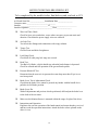
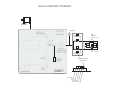
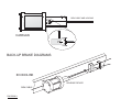
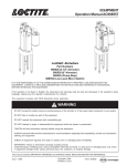
1
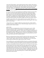
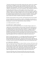
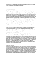
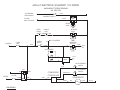
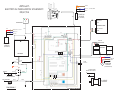
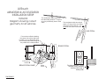
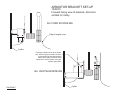
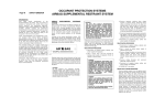
8000 INSTALLATION GUIDE and DIAGRAMS Low-Effort Gas and Brake Control _____________________________________________________________________________________ Pneumatic Gas & Brake Installation Guide Rev. 7/10/03 I. Introduction. Pg. 1 (See also “AirTouch product info” or “User Manual”) A. Design B. Features II. Operation A. Normal B. Back-ups Pg. 2 III. Handle Options A. Force B. Orthotics C. Direction Pg. 4 IV. Installation Procedure. A. Mounting 1. Air Box 2. BU brake 3. Air motor 4. Control Module B. Hook-ups C. Adjustments Pg. 6 V. Maintenance. Pg. 12 VI. Operational Warnings Pg. 13 Pg. 6 Pg. 6 Pg. 7 Pg. 9 Pg. 10 Pg. 11 INTRODUCTION The ”AirTouch” was designed by Creative Controls, Inc. to operate the primary gas and brake functions for drivers that require assistance. There are many features of ”AirTouch” that make it ideal for drivers in need of low effort/low travel gas and brake hand controls. Its ease of operation and installation will set a new precedent. SAE, DOT and VA standards or recommendations were all closely used as guidelines in its design. The next generation of this trend-setting product, AirTouch Extreme, has now been introduced. “AirTouch Extreme” provides power and is responsive like AirTouch but incorporates a pneumatic closed loop control system with pneumatic valves that can accurately position the actuator shaft and hold it in position with a high degree of accuracy and force. The system accomplishes the long sought after goal of using pneumatic technology for motion control, to accurately apply the brake and gas at any desired position with minimal input effort. Space requirements are minimal, which means this is a versatile control that can be mounted in a variety of vehicles. No components need to be installed under the hood and no modifications to OEM parts are required either. The simple installation allows the system to be transferred to other vehicles. The hand control can be turned off by a locking toggle switch to be driven as normal by other family members, service personnel or a valet. The toggle switch is a locking style, which requires the user to lift up on the lever in order to change positions. When the system is turned off, the driver is made aware by the fact that the control does not respond and that the system’s LEDs do not illuminate. The prime source of power for the hand control is its air system, consisting of a 12 volt compressor and air tank. The system also incorporates all the necessary back-ups and warnings to maintain safe operation. The brake is actuated through a pneumatic motor that applies force by means of a drive arm and roller to the pedal. It will even stop the vehicle when there is no power assist from the vehicle. The accelerator is activated through a cable connected to the accelerator pedal arm. The control handle body is compact and does not intrude into the driver’s area or make fitting difficult. It can be easily mounted on the door without blocking entrance through the driver’s door. Incorporated with the control is an air operated parking and emergency brake to provide automatic back-up braking. A vehicle that sports a CCI AirTouch Extreme Control can still be driven by an able-bodied driver since there are no modifications the OEM controls. This means no modification to the brake system and that all manufacturers’ warranties remain in effect. This also allows for better drivability by an able-bodied person. 1 OPERATION The normal operation is explained in the user’s manual supplied with each AirTouch hand control. Familiarize yourself with that manual as well as this installation guide. We also recommend that a copy of both the manual and this guide be kept in your possession for future reference. The user manual must then be passed on to the user and their understanding of it should be assured. Refer to the user manual. The AirTouch system operates by pushing the control lever to accelerate and pulling it to brake. The input at the lever is transmitted to the air motor through the CM, Control Module. There is a position sensor on the air motor that relays the position back to the CM and facilitates rapid and accurate tracking of the lever inputs. The air motor tries to track the lever position exactly. When a load is experienced on the brake roller, the air pressure required to apply the necessary force increases. The CM increases the valve opening to the air motor in proportion to the difference between the input on the lever and the actual position sensed at the air motor. Supplied with every AirTouch is a back-up brake. If the air motor fails to operate properly, the back-up brake will take over and stop the vehicle by means of a springloaded cylinder. This happens by way of three different means. The push-button on top of the control handle body can be depressed, the handle lever can be fully pulled back in the direction of brake, or the pressure in the tank falls below about 30 psi. Furthermore, with the interruption of ignition power, the air to the back-up brake will be dumped causing it to apply. The back-up brake can be modulated or applied fully by either pulsing or constantly holding these switches. Though the back-up brake will not instantly stop the vehicle, corrective action must be taken. In the event that the back-up brake must be used to stop, it is imperative that the vehicle be steered to the side of the road and out of traffic. While driving the vehicle with the system on/off switch turned to off, the air must be maintained to the back-up brake cylinder to keep the brake released. Therefore, the power to the compressor must be maintained and the switch only turns off power to the CM. When the system is turned off, the driver is made aware by the fact that the control does not respond and that the system’s LEDs do not illuminate. The system pressure gauge will likewise not indicate what the air pressure is. However, since the back-up brake cylinder has a limit switch, it will turn on the OEM brake-warning indicator to warn the driver if the back-up brake is not released for driving. When the vehicles ignition is off, the parking brake is automatically applied. Also, when the ignition is on and there is a failure to release the AirTouch back-up brake, the user will see the OEM park brake indicator illuminated on the dash. In either case, the vehicle should not be moved or towed for more than 600 yards. Doing so may degrade the condition or effectiveness of the OEM parking brakes, which at some point could be detrimental. The vehicle can however, be moved or driven off to the side of a roadway without harm to the brakes or hand control. 2 If it becomes necessary to move the vehicle for longer distances when the parking brake cannot be released, the following procedure should be followed. The emergency brake release lever can be unlocked and flipped over, therefore releasing the cable that pulls on the OEM parking brake. Typically mounted under the vehicle, this lever is painted yellow and no tools should be required to operate this. The vehicle can then be towed or pushed. However, it is mandatory that this lever be re-engaged before the vehicle is driven again, as this would pose an extreme danger. Connected to the bottom of the filter is a drain valve. This is normally closed and will open for 8-10 seconds whenever the vehicle is shifted into reverse. Incorporating a timer prevents prolonged draining of the air. This is sufficient to expel any collected moisture from the filter. The timer will continue to operate with the hand control turned off since air is still required to release the back-up brake. The air is expelled to the exterior of the vehicle and there should usually never be any measurable amount of water from this drain collected under the vehicle. As mentioned elsewhere in this and in the owner’s manual, is the need to have the filter changed on a regular basis. If this is not performed regularly, the operation of the hand control may change. In severe cases the compressor may take a long time to pump up the air to its normal level or the hand control may act “sluggish”. Built into the control system are self-checks to alert the driver to other potential problems. This may include, but not limited to, wiring problems such as severed or partially severed wires, unplugged connectors, malfunctioning solenoid valves, loss of ground or power at any point, or loss of air at any point. In the unlikely event of such a problem, the buzzer and the red LED will again turn on to alert the driver. It is expected that the buzzer and LED will turn on for low air pressure, but coming on even when the air pressure is within the operating range is a possible indication of a more serious problem. When the red LED and buzzer comes on after the system is booted up, they will turn on and blink in a distinctive pattern, thus indicating different types of problems. A double blink pattern indicates there is a problem with the feedback circuit from the air motor to the CM. A triple blink pattern indicates there is a problem with the feedback circuit from the control handle to the CM. A continuous buzzing, as mentioned previously, will alert the driver of low air pressure or will indicate there is the possibility of other problems. In any case, the vehicle should not be driven with any warning alarm. 3 OPTIONS The required force to move the lever can be changed. Typically, the hand control is assembled with the medium force range of about 3 ounces at a 6” moment arm. This force can be increased or decreased by about 1 ounce. Doing so is best accomplished at the factory, but is possible in the field if necessary by changing the internal centering springs. An important feature of the AirTouch control is its versatility. Specifically, the reaction of the air motor can be altered in relation to the input of the handle lever. If a driver requires limited response of the accelerator, the air motor can be programmed to react more slowly to the inputs of the handle lever. This is especially beneficial to a driver trainer and to a driver who may require some training or time to develop a sense of feel for the hand control or driving a new vehicle. The feel of the hand control can therefore be altered based on the needs or experience of the driver. Special programming can be accomplished by downloading different information to the control module. This allows for the altering of certain features or characteristics of the hand control and the addition of certain options. In the future, this can be accomplished by simply connecting to the control module via an Ethernet or wireless port, without removal of any components. Furthermore, a driver trainer can, upon each start-up, select one of a few different modes by changing a selector switch. The standard control has a round knob on top of the handle lever. CCI manufactures two different orthotic devices, which again, are best installed at the factory. A horizontal pin or a tri-pin device with turn signals can be applied to the lever in place of the standard knob. This change, as well as the application of different devices, can be done outside the factory also. Removal of any of the three devices will expose a 5/16-18 threaded hole in the top of the lever to provide an attachment point for a custom orthotic device. The Tri-pin device is designed to provide a horizontal surface throughout the range of motion of the lever. It also incorporates a side-to-side rocker motion to operate two switches that can be used mainly for turn signals, but also for the control of other devices. To install a tri-pin device, place the H-shaped spacer on the top of the lever. Insert the 5/16 button head cap screw through the flat side of the horizontal shaft and the spacer and thread into the lever. Slip the tri-pin base onto the shaft with the link toward the rear and retain it with the snap ring. Fasten the link to the handle body cover using the ¼ x ¼ shoulder screw. Test the device for free movement. Adjust the pins in the slots to fit the users hand. Also make necessary adjustments to the pivot force by adjusting the button head cap screws on top of the tri-pin plate, and the switch sensitivity by turning the setscrews on either side of the plate. Over-adjustment of either may cause the switches to not operate or not turn off. In any case, only very slight incremental adjustments need be made. Route the telco cord and secure it so that it has enough of a loop to allow for full travel of the lever without restriction. 4 The horizontal pin is available in a stock size of 5/8 diameter and 3” long. It has a rubber grip that can be trimmed to fit a pin that has been shortened. It is installed in the same manner as the shaft for the tri-pin device. When installing a custom orthotic device, it must be assured that whatever the device, it will not interfere with the movement of the lever or the operation of the switches on top of the control box. Weight and size are of great importance in this regard. The orientation of the control handle body can be changed, though it is very strongly recommended to be forward for accelerator and back for brake. It can be rotated to instead operate in a side-to-side orientation. Doing so may require the use of a special orthotic or user interface device. 5 INSTALLATION The installation procedure can be divided into four different groups: The mounting of the air box, the back-up brake, the air motor and the electrical components. This is also the basic order in which they are installed, although not mandatory. The most critical and most involved stage is the mounting of the air motor. Extra time and care may be involved with this stage. Thoroughly review the wiring and pneumatic diagrams before starting the installation in order to make good installation choices. AIR BOX The air box contains the air compressor and its control, the filter, the pressure switches, the air tank and some of the air valves. In a van, the air box is mounted behind the rear bench seat in a vertical position. However, it can also be mounted in other locations to suit different vehicles or any special considerations for the user. For versatility, the air tank can be mounted on the side of the air box, or even separate of the air box. For the latter option, it is up to the installer to provide secure mounting of the tank and safe and proper routing or the air line. The main considerations are the accessibility of the components, the safe and proper routing of the air lines and wires, and to keep the air filter in an upright position. Before drilling any mounting holes, be certain that they will not interfere with any lines or wires under the floor or carpet padding. It is not necessary to remove the carpet under the area that you will be mounting the air box unless to check for wires or if it might touch the compressor and hamper it’s cooling. The carpet padding under the air box should be cut out to prevent the carpet from interfering or coming too close to the components. Secure the air box with a minimum of four ¼” bolts with large fender washers underneath. The wires and tubes exiting the box should be routed through the interior of the vehicle, while avoiding all sharp edges, turns, pinch points and hot spots that could possibly damage or sacrifice their functionality. When the wires or tubes pass under the bottom edge of the air box, spacers must be installed to prevent the box from pinching down on the wires or tubes. The wires will eventually be connected to the CM, while the air tubes go to the back-up brake and the air motor location as described in the pneumatic diagram. From the outlet of the drain valve in the air box, route the 1/8” tube to the exterior of the vehicle. Connect the 18-gauge purple wire from the middle terminal of the timer module to the OEM reverse light circuit. BACK-UP BRAKE Remove the OEM park brake pedal since it will not be used. This is also to gain room for the air motor. Pull the brake cable through the floor. The back-up brake cylinder will be mounted in a manner to pull on this cable. In some cases, (as with an E-150) it can be mounted in-line with the cable as it runs forward along the frame. In others, (as with a minivan) it may be necessary to mount the cylinder offset and route the cable in an scurve. End plates come fitted to the cylinder for mounting, but since there can be different situations, the finishing of a proper mount is done at the time of installation. The cylinder must be secured sufficiently to handle the stress of pulling on the brake without flexing or failure. Choose a location of the cylinder that will allow it to pull on the brake 6 in the most efficient manner. Loosely attach the cable from the cylinder to the exposed section of the parking brake cable with the cable clamps. After air pressure is developed and the cylinder rod extended, this cable will be adjusted to allow for proper travel by moving the clamps. Over-adjusting may cause the brake to either drag or not apply sufficiently. The goal is to adjust the back-up cable as tight as possible without dragging the brakes when it is released. The cable clevis pin can be removed during the installation or during servicing to allow the vehicle to be moved without sufficient air pressure in the system. If it becomes necessary to move the vehicle for distances longer than 600 yards while the parking brake cannot be released, the following alternate procedure should be followed. The back-up brake is equipped with a release mechanism that can be activated, therefore relaxing the cable that pulls on the OEM parking brake. This device is colored yellow and is positioned between the cable and the cylinder rod of the back-up brake. No tools should be required for this. The vehicle can then be towed or pushed. However, it is mandatory that this lever be re-engaged before the vehicle is driven again, as this would pose an extreme danger. * If the vehicle is to be equipped with back-up steering, this back-up brake should be installed concurrently, especially in the case where they might occupy the same area or possibly interfere with one another. AIR MOTOR There are two basic mounting brackets for the AirTouch air motor, one for a 2000+ Econoline and one for a 2001+ Chrysler minivan. For installation details on other vehicles, the installer should contact CCI. Other vehicles will require the fabrication of a bracket using the material supplied. This is the most time consuming and critical part of the installation procedure. The importance lies with the travel and alignment of the brake roller. The majority of this engineering and/or guesswork is taken out by the use of one of the basic brackets in the afore mentioned vehicles. Remove the rubber pad from the brake pedal. Slip the brake roller ramp over the left end of the brake pedal in such a way that the plate extends mostly above the pedal and “ramps” upward. Apply Locktite to the setscrews and tighten to secure it to the pedal. Trim and replace the rubber pad or apply grit tape in place of the pad. In any installation, the carpet should be pulled back from the area under the brake pedal in order to mount the air motor bracket directly to the floor and wheelwell metal. Bolt the air motor to the mounting bracket provided. Position the assembly between the left side of the brake pedal and the left sidewall. When the drive arm is rotated to its full extent in the brake direction, the roller should contact the ramp slightly below the top edge and fully apply the brakes. Likewise, the drive arm should not enter an over center situation on the brake pedal toward the end of its travel. In the same motor position, the drive arm, when allowed to rotate to the neutral position, should have a slight gap between the roller and the ramp. The drive arm can be rotated on the shaft by loosening the clamping screw near the end of the arm. When repositioning the arm, it should remain approximately flush with the end of the shaft. 7 The proper positioning of the motor and the motion of the drive arm has a few variables that all must be coordinated to ensure proper installation and operation. Some of the correct operation can be attributed to proper positioning of the motor and some can be attributed to proper adjustments. Therefore the exact positioning of the motor cannot be completely ensured until the system is partly operational. When installing the system in a Ford Econoline and Windstar or a Chrysler minivan, much of the guesswork is eliminated with the use of the brackets supplied by CCI. The air motor shaft is capable rotating 135 degrees. Generally, 90 degrees is used for brake travel and 45 is used for the accelerator. This rotation combined with the necessary travel of the OEM pedals, affects the positioning of the air motor and is the key factor in its installation. On some vehicles it is possible to slightly depress the wheel well outward to gain more room for the air motor and the tube connectors. Installation should proceed with this in mind. With the motor positioned as best as possible, mark through the brackets holes and drill for the mounting bolts, being careful not to interfere with anything on the other side of the floor or wheel well. Secure the bracket with at least 3/8 diameter, Grade 5 bolts and backing plates to spread out the load on the floor or wheel well metal. ACCELERATOR INSTALLATION ACCELERATOR - FORD ECONOLINE Peel back or trim any interior panel that may be covering the left-upper engine cover clamp bracket. Insert the threaded leg of the accelerator cable bracket from the front of the clamp bracket until the holes line up. (Refer to diagram F) Screw in and tighten the two bolts and replace any interior that may have been moved. Unthread one stop nut from the housing adjuster on the loop end of the accelerator cable. Slide the cable through the slot and insert the adjuster in the hole in the cable bracket on the air motor. Attach the loop on the pin of the air motor and replace the washer and cotter pin. Remove the stop nut from the adjuster on the pedal end of the cable and insert the cable and adjuster through the hole in the accelerator bracket. Replace the nuts and secure. Drill a 3/16 hole in the pedal lever, 3/8” to the right of the OEM accelerator cable hole. Remove the ball chain coupler from one end of the ball chain and feed the chain backward through the hole in the pedal. Temporarily connect the other coupler between the ball on the end of the cable and the appropriate ball on the chain that allows the pedal to be fully released. Do not trim the chain until the system has been adjusted and tested. ACCELERATOR - CHRYSLER Remove the plastic dash panel under the column. Bolt the accelerator cable bracket to the under side of the bolster support. Unthread one stop nut from the housing adjuster on the loop end of the accelerator cable. On the air motor, slide the cable through the slot and insert the adjuster in the hole in the cable bracket. Attach the loop on the pin of the accelerator collar on the air motor shaft and replace the washer and cotter pin. Remove the stop nut from the adjuster on the pedal end of the cable and insert the cable and adjuster through the hole in the accelerator bracket. Replace the nuts and secure. Connect the ball chain to the ball stop on the OEM cable using the chain coupler. Connect the other coupler between the ball stop on the hand control cable and the 8 appropriate ball on the chain that allows the pedal to be fully released. Do not trim the chain until the system has been adjusted and tested. ALL OTHER VEHICLES Slip the accelerator cable housing over the accelerator cable and into the adjuster on the air motor. The accelerator cable passes under the steering column just in front of the steering wheel and curves back around under the dash to the top of the pedal. The critical considerations for this part of the installation are the travel of the pedal and the angle at which the cable pulls on the pedal. The cable is capable of 1 5/8” travel, so the point at which the cable is attached to the pedal should be able to travel at least that much also. On the pedal end of the cable housing will be the accelerator cable bracket to secure the housing. It should be positioned under the dash to provide optimum pull on the pedal. The typical attachment for the bracket is to the lower dash support metal, in line with the OEM accelerator cable. Center the cable adjuster in the bracket to allow for adjustment in either direction during the final stages of the installation. The ideal alignment of the accelerator cable will be in a line that is parallel to the OEM cable, and that starts from a point on the pedal that travels at least 1 5/8”. The cable must also not exit the adjuster at an angle at which it may rub on the edges, as well as any corners of other parts in the under-dash area. There are different methods of attachment to the accelerator pedal depending on the vehicle. A desirable feature is to have the cable be detachable from the pedal for servicing and set-up. The length of the cable is also important in that the cable can either pull not enough or too much. The air motor has the power to over-pull the OEM or the AirTouch cables if there is improper set-up or adjustment. ACCELERATOR - ALL VEHICLES The accelerator drive cog is designed to disengage with the cable when the air motor is rotated in the direction of the brake, and to only pull on the cable once the drive arm has reached the neutral position and rotates in the opposite direction. The point at which the cogs engage is adjustable by resetting the setscrew in the accelerator drive cog onto the motor shaft. When doing so, be sure that there is end clearance on the cogs in order that they do not bind with the motor or the drive arm, leaving a minimum 1/16” gap between these parts. The adjusters on either end of the cable housing provide additional adjustment to fine-tune the movement of the accelerator and to compensate for other adjustments made elsewhere in the system. CONTROL MODULE Location of the CM (Control Module) and the power supply should be considered next. The power supply must be situated in any convenient spot that allows access to the fuse and does not block air movement over at least half of its exterior for cooling purposes. Avoid locating it near any heating outlets or on any surface that would tend to add heat to the case. Secure the case to prevent its movement. The output of the CM power supply must only be used to provide power to the CM. The CM must also be secured to prevent movement and the introduction of additional heat or moisture, while being as near as 9 possible to the air motor. It essentially becomes the hub of the system, as all wires from each component are routed to this module. The removal of its cover may also be a consideration in finding a suitable mounting location. It is also important that the cable connectors not be situated in a location that would subject them to impact from objects, people or wheelchairs that may move around inside the vehicle. Make the electrical connections as shown to the power supplies and the CM following recommended safe practices. Allow for slack in the wires to prevent strain on the connections and to accommodate the removal and hook-up of the tubing or other components. Mount the monitor in sight of the driver to be easily seen while driving. Route the supplied tubing from the air box to both the back-up brake cylinder and the air motor using safe practices to avoid potential damage caused by heat, abrasion or kinking. The AirTouch system uses quick-connect type tube fittings for easy and consistent connections. These should provide a dependable air connection provided the tube is inserted straight and far enough into the fitting. For each tube connection allow an extra ½” for insertion, as well as extra length for smooth bends. Be sure the tube is able to insert about 3/8” into the fitting after initial contact. The connections also allow for easy tube removal by depressing the ring around the entrance to the fitting while pulling the tube out. Removal and reinsertion is not recommended more than three times for each connection unless there is enough extra length to trim off 3/8” from the end of the tube. When any tube is reconnected, it should be tested for leaks. A clean, square cut made with tube or hose cutters will provide a better connection. The use of wire cutters is not recommended. NOTE: Before connecting the air supply tube into the CM or the air motor valve, blow out the entire tube with clean compressed air to remove any possible foreign material. Apply split loom to the air supply tubing. Follow the diagram to make the necessary tube connections. Additional tubing is only available from CCI. The mounting of the handle body should be done after the installation of the rest of the system and comes with enough wire to mount on either side of the driver. Its cable can be plugged in to the CM without the handle body being mounted. Care should be taken though, not to damage the switches on top of the handle body while it may be lying about in the vehicle before it is mounted. Mounting the handle body is usually done after the driver has been fitted to the vehicle to determine the best location. The handle body can be located on the door if necessary using at least three of the mounting holes. Be sure your fasteners and materials are suitable to withstand the load of daily use. Removal of the handle body cover is not necessary and should not be done unless authorized to do so by the factory. Mount the air gauge within sight of the driver and tee it into the supply air before it enters the air motor. The gauge is supplied with extra fittings to allow the 1/8” tube to lead in either from the side or straight back. The CM comes from the factory with multiple reaction modes incorporated into the control. The mode in which the control will operate, is selected upon start-up by the position of a selector switch. The mode can only be changed by restarting the system with the switch in a different position. Typically, the switch is located on the CM, but can be mounted elsewhere when necessary. With this type of set-up, a “training” mode can be provided that causes the air motor to be less reactive and to have limited travel, allowing the user to become accustomed to the control. For installation, the CM should be started 10 in “normal” mode to allow for proper set-up. After the initial set-up is complete, switch the control to “training” mode to ensure that the movement of the accelerator is restricted for the accelerator. Once the connections are made, the system can be turned on to begin the final testing and adjustment stage. Until adjustments have been made and components secured, the accelerator cable should be left unhooked and the brake should not be applied without the engine running (for power assist). This is to prevent damage to the system or the vehicle. Lift and flip the system on/off switch (on top of the handle body) to off and turn on the ignition. The pump should cycle once when the ignition is turned on. Begin with testing the air supply and the air connections. A soapy water solution can be applied to all tube connections except those that might be near the CM, as moisture inside the CM enclosure will hamper its operation. If you suspect that moisture has entered the enclosure, turn off the ignition and gently blow-dry the inside, then let the control set for 6-10 hours before re-powering. When the back-up brake cylinder has extended, clamp the cable onto the OEM brake cable. Push and hold the “brake set” button on the handle body to test the setting of the brake. Likewise, turn off the ignition and also check the setting of the brake. The pull exerted by the back-up brake should not put unnecessary side force on the OEM cable and should be sufficient to slow the vehicle to a stop with the engine idling in gear. Adjust the tension on the brake cables until they are as tight as possible without causing the parking brakes to drag with the brake released. This may require a road test and/or elevating the rear end for proper adjustment. With the ignition on, the pump will continue to operate and cycle on and off as necessary, therefore releasing the parking brake when the pressure is above 30psi. The red LED on the monitor will extinguish and the green LED will illuminate when the system pressure rises above 40 psi. With the mode switch still in the “normal” position, turn the system switch to on to apply power to the CM and allow the entire system to operate. With the handle lever in the neutral position, the drive roller should find its neutral position where it is not pushing on the brake pedal nor pulling on the accelerator. This adjustment stage involves the testing of the air motor position and of the settings of the CM. Should the air motor not be capable of full braking or releasing, it may require either changing the mounting bracket or adjusting the brake lever on the shaft. Also, with only the ignition on and the accelerator cable still disconnected, move the control lever to the full accelerate position and observe the travel of the cable. Apply the end fittings to the cable at the proper position to give nearly full gas without any overtravel of the OEM pedal. Adjust the accelerator drive cog on the main shaft and adjust the cable adjusters to allow for proper accelerator travel. Again, this travel is also affected by the settings of the CM and the brake neutral position and should be taken into consideration as a whole. When the accelerator cable is adjusted, tighten the locking nuts and the setscrew in the collar on each adjuster, thus locking in the cable housing but not pinching the cable. With the engine running, pull the handle lever to the full brake position. At this position or with a very slight nudge, ensure that the back-up brake air is released from the 11 cylinder, causing it to pull the brake cable. Should this not happen, call the factory for testing procedures. Also, should the air motor not operate properly at this time, check the power sources and all connections according to the diagrams, then call CCI for suggestions on troubleshooting. A final leak test should be performed on the air lines that feed the air motor beginning with the supply valve in the air box. When testing the air fittings on the air motor, the handle lever should be held in both the full gas and full brake positions in order to build full pressure in the cylinder lines. CAUTION: DO NOT allow any water to drip down or enter into the CM or the solenoids on the air motor, as it may hamper its operation or cause shorting. FINAL CHECKS Thoroughly inspect and test the installation checking its operation and integrity. Check the torque of the various nuts and bolts and the securement of the tubes and wires. One of the very last steps requires the pinning of the drive arm so that there is no chance of it slipping on the shaft. Only when the system has been completely tested and adjusted, drill a hole for the supplied roll pin radially into the shaft through the drive arm without allowing it’s setting to change. Tap in the roll pin being sure it engages in both parts and cut off any excess. Once this is done it may be difficult to change the setting later. Consult with the factory if this becomes necessary. Thoroughly instruct the user on the operation of the hand control and its back-ups and explain the necessary maintenance that the system will require. Be sure they maintain a copy of the users manual for reference and explain that it covers the maintenance schedule that is expected to be carried out. Attach the brake release placard to the driver’s visor. MAINTENANCE Regular maintenance appointments must be kept with your customer. It is important that the vehicle owner keep regular service appointments as scheduled by the vehicle manufacturer. Maintaining the original equipment is vital to safe operation. Replace the AirTouch air filter every four to six months, depending on vehicle usage and the local weather conditions. Replacement filter elements are available from CCI, but a new, sealed spare should be kept on-hand by either the installer or the vehicle owner. Whenever the filter casing is reassembled, it should be tested for leaks as well as the fittings on the end. Every six months, inspect the entire AirTouch system and the condition of all the components. The inspection should check for loose or worn parts as well as the operation of all moving parts. Also check the wiring and air tubing for abrasions or nicks and their securement. Check the adjustments and the condition of the brake and accelerator drive arms. The components of the hand control must be kept clean and dry. Low pressure compressed air blown on the parts is usually sufficient to clean the parts. Should you or the customer notice any change of operation or the failure of any part, notify CCI before driving the vehicle. Safe operation of the hand control requires that the 12 vehicle be properly maintained on a regular basis as explained in the vehicle owner’s manual. For our records, the hand control has a serial number listed on the side of the control handle body. It is mandatory that the name and address of the customer be supplied to us with the serial number. Should you, or they, have a change of address we must be notified so that we may still send any bulletins or notices. ! WARNINGS: ! • Do not operate the vehicle while the OEM Brake warning indicator is illuminated. • Never operate the vehicle while the back-up brake cable is released. • Do not tow or push a vehicle equipped with an AirTouch system for more than 600 yards without having the back-up brake lever released. For any longer distances, it should be hauled on a flat-bed type truck. • Do not operate a vehicle equipped with an AirTouch system when the “CHECK SYSTEM” LED is illuminated. • Only factory authorized personnel shall be allowed to maintain, troubleshoot or repair any component of the AirTouch system. • Do not attempt to drive the vehicle with the AirTouch hand control without proper training. • Only the intended driver should operate a vehicle equipped with an AirTouch hand control. However, if the vehicle must be driven by an able bodied driver, it can be done so in the normal manner with the “valet” switch in the off position. • Keep regular maintenance appointments with your AirTouch customer or direct them to an authorized facility that can. • Failure to have the AirTouch filter changed on a regular basis as described may void the warranty and/or cause severe failures to the operation of the control. 13 AIRTOUCH INSTALLERS CHECK LIST To be completed by the installer before final delivery and sent back to CCI. AirTouch Serial No._______________ Installation Date _______________ Customer name ______________________________ Installer ______________________________ of ______________________________ Installers signature ________________________ Date _______________ Wire And Tube Check Check for loose wires and tubes; secure where necessary to prevent strain and abrasion. Check that the power supply wires are soldered. Air Leak Test Test all air tube fittings and connections with soapy solution. Torque Test Check all nuts and bolts for tightness. Lock Ring Check Check that all cable plug lock rings are secured. Road Test Test Back-Up Brake: vehicle should stop when the brake button is depressed. Check for smooth and full operation of the gas and brake pedals. Pressure Bleed-Off Test Determine that the reservoir air pressure does not drop more than 30 psi over a two-hour period. Brake Lever Travel Adjustment Check Check that the brake lever cannot be pressed any further with the handle lever pulled to its full brake position. Brake Lever Pin With all adjustments and previous checks performed, drill and pin the brake lever to the shaft of the air motor. Make sure the Monitor/buzzer is mounted within the range of sight of the driver. Instructions and Operation Explain to the user the operation of the hand control and ensure that they received and have read the operation instructions. Attach the brake release placard on the driver’s visor. 14 AirTouch PNEUMATIC SCHEMATIC B.U. BRAKE CYLINDER 70 PSI SWITCH DUMP VALVE (W/WHITE WIRE) GAUGE 50 PSI SWITCH AIR MOTOR BRAKE CYLINDERS MANIFOLD AIRMOTOR SHUT-OFF VALVE (W/BROWN WIRE) FILTER PRESSURE SENSOR ACCEL CYLINDERS AIR MOTOR VALVE MANIFOLD SPITTER VALVE COMPRESSOR AIRBOX ACC. EXHAUST BRAKE SUPPLY AIR ACCELERATOR BRAKE EXHAUST AirTouch ELECTRICAL SCHEMATIC 12V SYSTEM excluding Control Module ver. 08/27/03 TO OEM PARK BRAKE SWITCH BLACK BRAKE CYLINDER MAGNETIC SWITCH TIMER PURPLE TO OEM BACK-UP LIGHTS SPITTER VALVE HANDLE LIMIT SWITCH EMER. BRAKE SWITCH SYSTEM SWITCH 5 AMP FUSE IGNITION RED WHITE BU BRAKE VALVE RED TO CONVERTER WT OFF ON WT GREEN WHITE AIRMOTOR SHUT-OFF GREEN TO I/O CM BUZZER R RED G MONITOR YEL RELAY TO I/O CM BLACK 50 PSI PRESSURE SWITCH BLUE RELAY RED BATTERY WHITE COMPRESSOR CONTROL BOX 15 AMP BLACK GREEN WHITE WHITE/BLACK COMPRESSOR RED GREEN DIAGRAM B 70 PSI PRESSURE SWITCH RED BLACK BLACK RED AirTouch BROWN WHITE ELECTRICAL INSTALLATION SCHEMATIC 08/27/06 BLUE, 5V BLACK TO I/O, CM BLACK POSITION SENSOR 18/6 (IN HANDLE) WT MONITOR 12V INPUT GND 9 CONVERTER 10 RD 20/3 RED BROWN, TO I/O CM WHITE BLACK GN BLUE, 5V 1 GN 2 RD GN BK Gnd 12V on/off WT GND WT WT BLACK 24V OUTPUT BK WT +24V 8 RD GN YL GN PRESSURE SENSOR VALVE MANIFOLD RD RD (IN AIRBOX) AIR MOTOR RD BL -5V GND AIR BOX BL +5V 6 RD 5 BL BL GN/Y GN/Y BLUE, 5V 4 RD 18/6 BLACK 11 BROWN BL 12 R W B 20 K MODE SWITCH GN WHITE 1 2 3 14/2 RELAY GREEN 15 AMP CIRCUIT BREAKER 12V IGNITION 8 7 6 5 4 3 2 1 WT BK BK/BL GN WHITE 8 7 6 5 4 3 2 1 BLACK 14 B.U. BRAKE CYLINDER A-D WHITE 87 86 1 3 2 4 30 BN 5 AMP FUSE BN BN BN DIAGRAM C POSITION SENSOR TO OEM PARK BRAKE INDICATOR WT 85 BLACK TO I/O, CM (IN AIRMOTOR) RED BATTERY BLACK CONTROL MODULE AirTouch AIRMOTOR & ACCELERATOR INSTALLATION SETUP 10/02/03 Diagram showing correct geometry for all vehicles. The accelerator cable should exit the cable fitting within a 5o range so as not to prematurely wear out the cable. The accelerator cable should pull within a 5o range of the oem cable. Total travel of the cable is 1-1/2“. Do not allow over-travel of the oem pedal. GAS PEDAL For maximum effective braking, the center of the drive shaft must be within 1-1/4“ of the brake ramp, and not behind the bottom edge of the pedal in the neutral position. BRAKE PEDAL ACCELERATOR o RANGE, 45 BRAKE PEDAL RAMP DIAGRAM D BRAKE o RANGE, 90 Provide maximum 1/8 gap between end of actuator shaft and left edge of brake pedal. AIRMOTOR BRACKET SET-UP 10/02/03 Forward facing view of brackets. Airmotors omitted for clarity. 92+ FORD ECONOLINE Edge of engine cover A-pillar Position the bracket close to the wheelwell. Drill through pinch weld area close to the wheel-well and apply backing plates and locking nuts inside of the wheel-well in three locations using 3/8, medium grade bolts. 96+ CHRYSLER MINIVAN DIAGRAM E A-pillar ACCELERATOR BRACKET SET-UP 10/02/03 Ford Econoline 92+ Accelerator Bracket OEM Engine cover bracket 3/8" OEM throttle cable on pedal To Actuator Drill 3/16“ hole Insert ball-chain, adjust, and cutoff extra. Chrysler Minivan ‘96 to current. Accelerator Bracket Lower dash support Accelerator bracket must be in line with OEM cable. To Actuator OEM cable Insert ball-chain, adjust, and cutoff extra. Clip coupler onto OEM cable. DIAGRAM F 99+ FORD WINDSTAR ACCELERATOR AND BRAKE BRACKETS 10/02/03 Airmotor omitted for clarity. Drill through pinch weld area and apply backing plates and nuts inside of the wheel-well in four locations using 3/8, medium grade bolts. Adjust and attach the accelerator ball chain. Accelerator Bracket; roller rides on top of pedal arm. Use the firewall boot studs to secure the accelerator bracket. Accelerator Cable Bracket A-pillar Bottom of bracket should be even with OEM floor stud. OEM Bolts Attach to top of accelerator roller lever. DIAGRAM G Insert ball-chain, adjust, and cutoff extra. OEM Center Console Support, drivers side OEM CABLE AND HOUSING CARAVAN 3 2 1 BACK-UP BRAKE DIAGRAMS ECONOLINE RELEASE DEVICE OEM CABLE DIAGRAM H