1
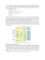
The above elements were used for integration with EDR software simulation and EM integration. EDR is a rack facility
internal to Columbus where two types of drawers can be integrated. The Protein Crystallisation Diagnostic Facility
(PCDF) is the first payload for EDR. A full EDR PCDF System Simulator (EPSS) was used to support the development
and training at the USOC while the EDR EM was in use for other activities or the PCDF-EM was not available. Once
the EDR-EM became available the simulator proved to be still useful in the context of fault-injection simulation and for
training. As shown in Fig. 2 a similar approach was used to integrate the hybrid approach taken for ESM.
HYBRID CONCEPT PAYLOAD SIMULATION
The approach taken with the EuTEF simulation was different compared to the EDR software simulation as a full EuTEF
engineering model was definitively not available. The approach is to be contrasted with a full software simulation and a
full instrument payload development model with representative hardware. At the Erasmus USOC this was done for one
demo drawer [3], but for EuTEF a hardware based effort was felt to be too expensive for nine instruments. Software
simulation was feasible for EDR/PCDF in the EPSS project. A simulation of a LIDAR instrument on ISS was exercised
previously [4]. To ensure sufficient realism a compromise between hardware and software was selected.
The main design drivers for the ESM were:
1. Reuse the EM of the EuTEF DHPU (Data Handling and Power Unit) as a central core for the simulator to
guarantee the required hardware compatibility with the RS-422 and Mil-Std-1553 standards for the data handling
interfaces.
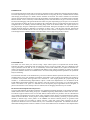
2. Use of an Earth Viewing Camera Development hardware model which was assumed to become available later
during the development.
3. Use of an instrument MDB(i-MDB) TM/TC database to ensure consistency for the instrument interfaces with other
Erasmus USOC developments and to reuse potential improvements as the information about the specific
instruments was limited at the start of the project.
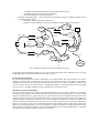
Fig. 3 depicts the central place of the EuTEF DHPU EM in the hybrid architecture concept and its conditioning and
monitoring. The architecture contains a generic part including a model for data interfacing with the EuTEF DHPU and
an instrument specific part implemented via a high level rule-based coding formalism. The ESM implements all the
interfaces of the EuTEF DHPU EM. Both the RS-422 and Mil-Std-1553 type instrument interfaces have been
implemented within a EuroSim simulation environment. Stimuli to represent the power usage of instruments and
thermistors for EuTEF monitoring have been implemented. The Earth Viewing Camera (EVC) Development Model
(DM) is a realistic model for the data handling for the EVC Flight Model as integrated in EuTEF for which realistic
hardware interfaces would be needed.
Fig. 3.The EuTEF DHPU EM is conditioned and monitored with representative data interfaces.