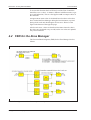
1
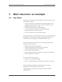
TAC Xenta Zone System Guidelines 421 Dig I/O 300 XVent 101-1VF 101-1VF 101-1VF 101-1VF 101-1VF 451 Anlg I/O 101-1VF 101-1VF 401 ZM 101-1VF 101-2VF Router 102-B 102-B 102-B 101-2VF 101-2VF 101-2VF 103-A 103-A 101-2VF 101-2VF 101-2VF Router 102-EF 102-EF 102-EF 102-EF 102-B 103-A 103-A Router X300 XHeat 0-004-7637-1 (GB), 1998-12-01 TAC Xenta Zone System Guidelines Foreword Foreword This manual describes the recommended working procedures when designing a zone system, based upon TAC Xenta products (version 3.1), by help of TAC Menta for the application programming and with TAC Vista as the supervisory system (also both of version 3.1). We use MetraVision as an example on a binding tool, but thanks to the open LonWorks technology also other binding tools may be used. The manual requires that the user has some basic knowledge of the products. TAC AB, 1998-12-01 0-004-7637-1 (GB), i (2) TAC Xenta Zone System Guidelines Foreword Revisions list Art.no. Comments Editor 0-004-7637-0 First version. KW 1998-04-30 0-004-7637-1 Revised according to TAC Vista/Menta/Xenta 3.1. KW 1998-12-01 ii (2), 0-004-7637-1 (GB) Date TAC AB, 1998-12-01 TAC Xenta Zone System Guidelines Contents TAC Xenta Zone System Guidelines Subject to modification. © 1998 TAC AB Contents 1 1.1 1.2 1.3 2 2.1 2.2 2.3 3 3.1 3.2 4 4.1 4.2 4.3 5 5.1 5.2 5.2.1 5.2.2 5.2.3 5.2.4 5.2.5 6 6.1 6.2 Introduction ................................................................................................................. 1:1 Purpose ............................................................................................................................................... 1:1 Scope and Limits ................................................................................................................................ 1:1 More information .............................................................................................................................. 1:1 Working method .......................................................................................................... 2:1 Basic project analysis ........................................................................................................................ 2:1 Programming guidelines ................................................................................................................... 2:2 Commissioning ................................................................................................................................... 2:3 Main structure: an example ....................................................................................... 3:1 The Plant ............................................................................................................................................ 3:1 Acronyms and IDs ............................................................................................................................. 3:4 Zone Functions ............................................................................................................ 4:1 Signals and Points .............................................................................................................................. 4:1 FBD for the Zone Manager .............................................................................................................. 4:2 The most important settings ............................................................................................................. 4:4 Programming ............................................................................................................... 5:1 Preparations ....................................................................................................................................... 5:1 Programming ..................................................................................................................................... 5:4 The Application program of TAC Xenta 300/400 ............................................................................... 5:4 Configuring the network ...................................................................................................................... 5:4 Configuring the TAC Xenta units ........................................................................................................ 5:5 Creating Templates in MetraVision ..................................................................................................... 5:7 Preliminary Description files for TAC Vista ....................................................................................... 5:8 Installation and Program download .......................................................................... 6:1 Program download to TAC Xenta 300/400 ..................................................................................... 6:1 Commissioning of TAC Xenta 100 ................................................................................................... 6:2 TAC AB, 1998-12-01 0-004-7637-1 (GB), 1 (2) TAC Xenta Zone System Guidelines 7 Commissioning the Network ...................................................................................... 7:1 7.1 7.2 8 Nodes and Routers ............................................................................................................................. 7:1 Completing the Description files ...................................................................................................... 7:3 Parameters and NVs in TAC Xenta 100 .................................................................... 8:1 8.1 8.2 8.2.1 8.3 9 Contents Parameter download ......................................................................................................................... 8:1 Binding the Network variables ......................................................................................................... 8:2 Binding with Templates ....................................................................................................................... 8:2 To restore the addresses in TAC Vista ............................................................................................. 8:3 Unit Maintenance ........................................................................................................ 9:1 9.1 Changing the application program .................................................................................................. 9:1 Appendix 1 General Zone System Limits ID items for the Nodes Index This manual contains a total of 30 leaves. ®TAC Xenta, TAC Menta and TAC Vista are registered trademarks of TAC, Sweden. ®Echelon, LON, LonTalk, LONWORKS and Neuron are registered trademarks of Echelon Corporation, California, USA. ™LONMARK and LonMaker are trademarks of Echelon Corporation, California, USA. MetraVision™ is a trademark of Metra Corporation, USA. 2 (2), 0-004-7637-1 (GB) TAC AB, 1998-12-01 TAC Xenta Zone System Guidelines 1 Introduction Introduction 1.1 Purpose This manual is designed to show how a zone system can be built with TAC Xenta components in a LONWORKS network, with software from TAC Menta and TAC Vista, using MetraVision as the binding tool. We work with a specific example and show how this is implemented, from the initial system design concepts, via the network configuration to commissioning and certain types of service. A basic idea is to use TAC Xenta 401 as a Zone Manager for a number of controllers of the TAC Xenta 100 series and to use “Templates” in MetraVision in order to simplify the binding of the variables that are to be exchanged between different units. 1.2 Scope and Limits The methods described in this manual are valid for the following products and releases. • TAC Xenta 400 v 3.1 • TAC Xenta 100 v 1.0 • TAC Xenta 300 v 3.1 • TAC Menta v 3.1 • TAC Vista v 3.1 • MetraVision v 3.0 or 4.1 (required only in chapter 9 when changing the application program, if you want to use the Generate/Restore Binding Spec. utility) • LonMark certified zone controllers from other vendors 1.3 More information The working method follows the guidelines which are given in the manual: • ”TAC Xenta family v3, Engineering Guidelines”, art.no. 0-004-7639. TAC AB, 1998-12-01 0-004-7637-1 (GB), 1:1 (2) TAC Xenta Zone System Guidelines Introduction The TAC Xenta 400 controller and the associated I/O-modules are described in the following documents: • “TAC Xenta 400 Handbook”, art.no. 0-004-7520. • “TAC Xenta Network guide”, art.no. 0-004-7460. • The data sheet for TAC Xenta 400 (C-92-05) • The data sheet for TAC Xenta 411/412 (C-92-10) • The data sheet for TAC Xenta 421/422 (C-92-15) • The data sheet for TAC Xenta 451/452 (C-92-20) • a short installation instruction, “0FL”, enclosed with each product The TAC Xenta 100 controllers are described in a number of data sheets and installation instructions and in the manuals for TAC Xenta 101, art.no. 0-004-7513, TAC Xenta 102, art.no. 0-004-7516 and TAC Xenta 103, art.no. 0-004-7526. The TAC Xenta 300 controllers and Operator Panel are described in the following documents: • “TAC Xenta 300 Handbook”, art.no. 0-004-7470. • The data sheet for TAC Xenta 300 (C-90-05) • The data sheet for TAC Xenta OP Operator Panel (C-98-05) • a short installation instruction, “0FL”, enclosed with each product TAC Menta is described in • “TAC Menta v3 User’s manual”, art.no. 0-004-7608. • “TAC Menta v3 Reference manual”, art.no. 0-004-7609. TAC Vista and those modules which are treated in this manual are described in the following manuals. • “TAC Vista 3.1, Operator guide”, art.no. 0-004-7571. • “TAC Vista 3.1, Basic functions”, art.no. 0-004-7647. • “TAC Vista 3.1, Communication TAC Xenta”, art.no. 0-004-7585. • “TAC Vista 3.1, Database generator”, art.no. 0-004-7578. • “TAC Vista 3.1, Colour graphic editor”, art.no. 0-004-7576. For a description of the interface between TAC Vista and the network (‘LonTalk Adapter) please refer to the corresponding product documents. 1:2 (2), 0-004-7637-1 (GB) TAC AB, 1998-12-01 TAC Xenta Zone System Guidelines 2 Working method Working method In this chapter we will present an overview of the normal working method in a project with zone controllers. We mainly use the same point-by-point numbering and adhere where suitable to the description given in the manual “TAC Xenta family, Engineering guidelines”, art.no. 0-004-7511. Note! It is important that you perform all steps and in the correct order, as, should any part be neglected, it will be difficult to catch up with this later during the project. In the succeeding chapters we will use a specific example to illustrate the details of the working method. According to the guidelines a project may be divided in three parts: A Basic project analysis B Programming guidelines C Commissioning 2.1 Basic project analysis Main structure 1) Study specifications and other project documents to get a clear picture of what is to be accomplished with the system. Network structure 2) Make a rough drawing on what is to be included in the physical network configuration (see also the “TAC Xenta Network guide”, art.no. 0-004-7460), comprising, for example: • TAC Xenta 300: control of units (heating/ventilation). • TAC Xenta 400: Zone Manager functions. • TAC Xenta 100: Zone controllers, which types (Fan-coil, VAV, Chilled ceiling) and how many. • Routers: Network separation for faster traffic and/or message routing. • Repeaters: Cable extension, more nodes. • TAC Vista: Central system, functions and network connection. TAC AB, 1998-12-01 0-004-7637-1 (GB), 2:1 (4) TAC Xenta Zone System Guidelines 3) Working method Determine the logical structure, that is, an ID-structure which will work both in TAC Vista and when you configure the network. You should probably use the method which is described in the Engineering Guidelines. Zone functionality 4) Decide which functionality will be required of the Zone system. • Which signals are needed and between which units (one – one, one – many). • Which points are needed and to which units are they to be connected. • Which groups should be created to cater for common functions. • Which functions should be included in the Zone Manager (TAC Xenta 400). • List the most important settings for the zone controllers (around 2-3 per unit) to simplify the commissioning. The settings should include the hardware type, actuators etc., which are to be controlled. (The remaining settings are easily made from TAC Vista.) 2.2 Programming guidelines Preparations 5) Prepare for the programming by creating a suitable structure for the necessary directories and files. Obtain the XIF files for the relevant TAC Xenta 100 units and any other LonWorks products. Programming 6) Use TAC Menta to build the most complex application program of the plant (regarding heat/ventilation) and the OP configuration. Test the program, first by simulation in TAC Menta; then the OP functions by connection to some unit with a downloaded application program. (This is listed as step no. 8 in the Engineering Guidelines.) Program and test, by simulation, the Zone Manager application. 7) Use for example MetraVision to configure off-line (that is, before it is connected) the complete network. • Define Channels (including any ‘Backbone’), Domains and Subnets. • Put all units with their correct logical unit names (IDs) on the respective channels. • Insert the required Routers between the channels. • Build the templates which later can be used for the binding of the standardised network variables (SNVTs). 2:2 (4), 0-004-7637-1 (GB) TAC AB, 1998-12-01 TAC Xenta Zone System Guidelines 8) Working method Build the TAC Vista functions: • Prepare the description files for the network and for all units. • Enter the preliminary description files into the data base of TAC Vista. 9) 10) Create in TAC Vista the graphics, reports, etc. for the application. Copy the files to the next application and continue the programming. 2.3 Commissioning The Installation work 11) Check what has been electrically connected and where the commissioning may be started. It is often desirable to start with the TAC Xenta 300 applications for heating/ventilation. Program download to TAC Xenta 300/400 12) Copy the data base and the required programs to the commissioning PC. Download the applications into the respective 300 units. Use the TAC Menta NCT to connect any I/O modules to the base units. If possible, make a preliminary test of the I/O modules. Download the application into the Zone Manager (TAC Xenta 400). Then use the binding tool, for example MetraVision, to install the 400 and 300 units with their I/O-modules, and to assign their network addresses. Commissioning of TAC Xenta 100 Look up the different Zone controllers, apply power and use the binding tool, for example MetraVision, to install the units and to assign their network addresses. Then use TAC Xenta OP or the binding tool to set the most important parameters according to the list from step 4. Commissioning the network Use MetraVision to install the nodes (for example the TAC Xenta units) and the Routers. The Neuron ID of the nodes should be entered directly via the keyboard or a bar code scanner. (It is also possible to do by help of the Service pin, but this method should be avoided as there is a risk for installing the wrong node.) At first, Routers are installed as Repeaters, as this will simplify the commissioning work. Note! TAC AB, 1998-12-01 The reconfiguration of a Repeater must be done before the Router is connected to the network. 0-004-7637-1 (GB), 2:3 (4) TAC Xenta Zone System Guidelines Working method When the units have been installed, you generate in MetraVision a report, which you can edit so that only the name of the units, their Neuron ID and type are saved. Using this report, you can enter the Neuron ID into the description files from step 8. Start TAC Vista and import the now completed description files. After that it should be possible to read the Subnet/node addresses from the network. Reconfigure those Repeaters that are to work as Routers (’Configured’ or ’Learning’). Parameter download TAC Xenta 100 Download the zone controller parameters (TAC Xenta 100 units) from TAC Vista. Binding the network variables Restart MetraVision to perform the network variables binding. This will be simplified if the templates from step 7 are used. During the binding procedure certain addresses for TAC Vista may be overwritten. In order to restore these, you must go back to TAC Vista, please refer to section 8.3! Functional test 13, 14) 2:4 (4), 0-004-7637-1 (GB) Now it is time to perform real functional tests and to backup the system. TAC AB, 1998-12-01 TAC Xenta Zone System Guidelines 3 Main structure: an example Main structure: an example 3.1 The Plant From here we will work with an example on a fairly small zone system. This example comprises • two TAC Xenta 300 to control the use of district heating (a heat exchanger in the basement, ’VS01’) and the ventilation ( an air handling system in the attic, ’LB01’) • one TAC Xenta 401, acting as Zone Manager • 15 TAC Xenta 101 to control Fan-coil heating/cooling • eight TAC Xenta 102 for VAV control • four TAC Xenta 103 to control chilled ceilings These units belong to a LonWorks network, which is connected through three Routers. The network is configured and supervised by a PC connected via an LTA-adapter, for example a PCLTA card. The following Network Variables (NV) are exchanged between the Xenta units via the network: • • • • • • Running mode control for the Zones Outdoor compensation of the Zone Group setpoints Current air flow from the VAV controllers Slave control of the VAV boxes Outdoor temperature to the ventilation unit and the Zone Manager Room temperature of the Zones NV may be of the following types: • TACNV = TAC Network Variable • SNVT = Standard Network Variable Type according to LONMARK. Please note that the example is presented with precisely these assumptions concerning NVs via the network. Other applications may require other NVs, other units, another configuration etc. TAC AB, 1998-12-01 0-004-7637-1 (GB), 3:1 (4) TAC Xenta Zone System Guidelines Main structure: an example Sending unit NV Type Receiving unit TAC Xenta 300 LB01 Vent.unit. Running mode TACNV Zone Manager Zone Manager Running mode SNVT All TAC Xenta 10x TAC Xenta 300 VS01 Current outdoor temp. TACNV TAC Xenta 300 LB01 Zone Manager Zone Manager Outdoor compensated Setpoint SNVT All offices Zone Manager Outdoor compensated Setpoint SNVT Auditoriums + Conference rooms Zone Manager Outdoor compensated Setpoint SNVT Other rooms at Floor 1 TAC Xenta 102 Auditorium (M) Slave control SNVT Xenta 102 Auditorium (S1) Xenta 102 Auditorium (S2) All TAC Xenta 102 Current air flow SNVT All TAC Xenta 10x Current room temp. SNVT Zone Manager Zone Manager Please refer to the Network guide for advice concerning the choice of TACNV or SNVT, especially the chapter describing “Networks that use SNVTs”. 3:2 (4), 0-004-7637-1 (GB) TAC AB, 1998-12-01 TAC Xenta Zone System Guidelines Main structure: an example Attic TAC Xenta 300: Ventilation unit 421 Dig I/O 300 XVent 451 Anlg I/O TAC Xenta 401: Zone Manager 401 ZM Cooling pump Office 3:1 Fancoil heating only Floor 3 101-1VF Office 3:2 Fancoil heating only 101-1VF Office 3:3 Fancoil heating only 101-1VF Office 3:4 Fancoil heating only 101-1VF Office 3:5 Fancoil heating only 101-1VF Office 3:6 Fancoil heating only 101-1VF Office 3:7 Fancoil heating only 101-1VF Office 3:8 Fancoil heating only Office 3:9 Fancoil heating/ cooling 101-1VF 101-2VF Router Floor 2 Auditorium M Master VAV air qual control Auditorium S1 Slave VAV 102-B 102-B Office 2:1 Fancoil heating/ cooling Office 2:2 Office 2:3 Office 2:4 Fancoil Fancoil Fancoil heating/ heating/ heating/ cooling cooling cooling Office 2:5 Office 2:6 Fancoil Fancoil heating/ heating/ cooling cooling 102-B 101-2VF 101-2VF 101-2VF Pentry VAV, electric air heater Conference room VAV Auditorium S2 Slave VAV 101-2VF 101-2VF 101-2VF Router Cafeteria VAV, electric air heater Floor 1 Reception Cloakroom VAV, VAV, electric electric air heater air heater Office 1:1 Chilled ceiling Office 1:2 Chilled ceiling Office 1:3 Chilled ceiling Office 1:4 Chilled ceiling Outdoor sensor 102-EF 102-EF 102-EF 102-EF 102-B 103-A 103-A 103-A 103-A Router Conf. Tool; TAC Vista PCLTA Basement TAC Xenta 300: Heating central X300 XHeat v 98-04-30 TAC AB, 1998-12-01 0-004-7637-1 (GB), 3:3 (4) TAC Xenta Zone System Guidelines Main structure: an example 3.2 Acronyms and IDs Follow the ID structure for the logical unit names that are recommended in the “Engineering Guidelines”. It must work both in TAC Vista/ TAC Xenta OP and when you configure the network. As the binding tool MetraVision and the network variables both use the English language, we recommend that you use English words or at least avoid special letters like å, ä, ö. Fore the NV names of the network the following standard designations apply. SNVT out: nvosignal name SNVT in: nvisignal name conf. parameters: ncisignal name 3:4 (4), 0-004-7637-1 (GB) TAC AB, 1998-12-01 TAC Xenta Zone System Guidelines 4 Zone Functions Zone Functions 4.1 Signals and Points In our example we have chosen the following exchange of signals. Running mode The running mode for the ventilation unit is fetched from the TAC Xenta 300 controller that handles the ventilation unit, via TACNV, from a signal labelled TF01_D, which indicates that the supply air fan has been started. From the Xenta 300 a 0 or 1 is sent to the Zone Manager (TAC Xenta 401), depending on if the fan is idle or started. The Zone Manager in turn, sends if the fan has been started the value 0 to Xenta 100, which corresponds to the value OC_OCCUPIED, otherwise the value OC_UNOCCUPIED is sent. This signal is sent via SNVT to all Xenta 100 controllers. Outdoor temperature The outdoor temperature sensor is connected to the basement Xenta 300; the value is then sent via TACNV to the Zone Manager and the attic Xenta 300. Setpoints The outdoor temperature value enters the Zone Manager curves (one for each Group), to produce an outdoor compensated value. The values from the curves can then be offset for each Group. The setpoints are sent to the different Groups, offices, conference rooms or reception, via SNVT. Air flow The current air flow for each VAV controller is sent to the Zone Manager via SNVT, adding the values to give the total air flow for floor 1 and floor 2. The sending of the room temperature The room temperatures is sent to the Zone Manager from the Zone Controllers. The Zone Manager input should be of the type no poll, this is indicated for TAC Xenta 300/400 in TAC Menta; the TAC Xenta 100 outputs are fixed as sending. TAC AB, 1998-12-01 0-004-7637-1 (GB), 4:1 (4) TAC Xenta Zone System Guidelines Zone Functions To secure their function the Send Heartbeat of the Zone Controllers should be set to a value 1–2 minutes, different in different units (to get an even distribution). The set value applies to all nvo output values of the controller. An approximate mean value is calculated based on those values that have reached the Zone Manager during the last 20 minutes, a period during which each unit should appear at least once. Please see the figure at the bottom of the opposite page! Also the min./max.-values are based on 20 minutes intervals, that is, the values are calculated every second, but the out-values are updated only each 20 minutes. 4.2 FBD for the Zone Manager The Function Block Diagrams (FBD) for the Zone Manager look as follows. FBD for Running mode and for Room temperature Setpoint 4:2 (4), 0-004-7637-1 (GB) TAC AB, 1998-12-01 TAC Xenta Zone System Guidelines Zone Functions FBD for the Sum flow per floor FBD for the Temperature values TAC AB, 1998-12-01 0-004-7637-1 (GB), 4:3 (4) TAC Xenta Zone System Guidelines Zone Functions 4.3 The most important settings To simplify the Zone Controller commissioning, you should list the two-three most important hardware settings. This can be done as you go through the specification. For example you can set the current actuator type, ON/OFF or increase/decrease. When it is time to commission the zones, you look up the Zone controllers, apply power, connect the TAC Xenta OP, change the settings according to the list and check that the controllers work correctly. At this stage it does not pay to perform a complete commissioning. Later we will connect the controllers to TAC Vista. Then all the settings that have been specified in the respective description files are downloaded to the controllers. The Network Variable nciAppOptions is used to set the outputs and application types. Here you may set, already at the first commissioning: • Occupancy sensor connected/not connected. • Energy saving (window contact) connected/not connected. • Slave mode active/passive. • Occupancy sensor normally open/closed. and so on. Examples on important parameter settings: Zone nciAppOptions nciMaxFlow nciNomFlow Cafeteria 00001000 11000000 300 300 Reception 00001000 11000000 60 100 Conf. room 00001000 11000000 150 200 Audit.: Master 00001000 11000000 200 250 Audit.: Slave 1 00001001 11000000 200 250 Audit.: Slave 2 00001001 11000000 200 250 In the TAC Xenta OP display you call up, for example, the following menu (bit 0 to the left) 24 nciAppOptions 00001000 11000000 and so on. 4:4 (4), 0-004-7637-1 (GB) TAC AB, 1998-12-01 TAC Xenta Zone System Guidelines 5 Programming Programming 5.1 Preparations To be able to connect the network to TAC Vista we must create a number of definitions and description files, which are used to update the data base of TAC Vista. The following items must be defined/described/performed in TAC Vista: • The connection of an LTA-adapter • A description file for the LTA-port and the LonWorks network and the TAC Xenta units and the TAC Xenta Groups • Application and description files for TAC Xenta 300/3000/400 • Description files for the TAC Xenta 100 units • Import of the description files to TAC Vista The files that are used or created can be put in a library with the following structure. Note! All of the procedure in this chapter can be done off-line from the network. Current project House house_ imp .des Network Command file LON1 .des LON1 .ndb Network configuration *.log Heat/ Vent *.xif *.mta *.des Application dependent files *.log *.xif Zonreg *.des Description and XIF files for the TAC Xenta 100 units A suggested project library for description files etc. TAC AB, 1998-12-01 0-004-7637-1 (GB), 5:1 (14) TAC Xenta Zone System Guidelines Programming The methods to create these files and their main contents are explained below. For the LonWorks network LON1.ndb Created by TAC Menta NCT (Network Configuration Tool). Contains data about the TAC Groups, Group masters and I/O modules. Imported separately to the data base of TAC Vista. Please refer to the chapter “Network configuration” in “TAC Menta User‘s Manual”. LON1.ndb must reside in the same catalogue as LON1.des. Note! If LON1.ndb is changed in any way, it has to be imported again to the data base of TAC Vista. LON1.des Edited according to the example below. Contains data about the current PC, the network port, the name of the network and of the file above. Imported to the data base of TAC Vista with the command file house_imp.des. The log file LON1.log will be generated. Note! The procedure requires the LON1.ndb file in the same catalogue. For the TAC Xenta 300/3000/400 units (Heat/Vent) *.mta Created by TAC Menta for each Xenta unit. Contains data about the application and its public variables. *.des Created by TAC Vista data base generator based on the information of *.mta. Contains data about the public variables. Imported to the data base of TAC Vista with the command file house_imp.des. The procedure requires the *.mta file in the same catalogue. *.xif Created by TAC Menta for each Xenta unit. Contains data about which SNVTs the application uses. *.log Log file created by TAC Vista data base generator as the file *.des is imported. Contains assorted status messages. For the TAC Xenta 100 units (Zone control) *.des Edited, using the corresponding template files *.dem, according to instructions later in this chapter. Contains application parameters, standard alarm texts and similar. Imported to the data base of TAC Vista with the command file house_imp.des. The procedure requires the *.xif file in the same catalogue. *.xif Exists in standard form for each type of TAC Xenta 100. Contains data about which SNVTs the unit uses. Used when *.des is to be imported to the data base of TAC Vista. *.xif files can be fetched directly from the units or downloaded via Internet at http://www.tac.se/tarai/ . *.sgr Standard graphics for a simplified display in TAC Vista of most of the SNVTs that are used in the different TAC Xenta 100 models. Fetched from the directory /TAC310/$ini. *.log Log file created by TAC Vista data base generator as the file *.des is imported. Contains assorted status messages. 5:2 (14), 0-004-7637-1 (GB) TAC AB, 1998-12-01 TAC Xenta Zone System Guidelines Programming For the import of description files to the data base of TAC Vista house_imp.des TAC AB, 1998-12-01 Edited according to an example later in this chapter, run as a command file, supplying the data base of TAC Vista with relevant information about the network, TAC Groups, applications, public variables and SNVTs. 0-004-7637-1 (GB), 5:3 (14) TAC Xenta Zone System Guidelines Programming 5.2 Programming 5.2.1 The Application program of TAC Xenta 300/400 Use TAC Menta to design the application programs of TAC Xenta 300, or start from the Xenta 3000 applications. Examples and guidelines appear in the “TAC Menta User’s Manual” and in the “TAC Menta Reference Manual”. Create suitable menus for the OP. Test the programs by simulation in TAC Menta. Treat the Zone Manager (TAC Xenta 400) in a similar way. 5.2.2 Configuring the network Open the binding tool MetraVision, specify File - Project - New, with the name House. All data for the new project will now be put in the catalogue \Program\Metra\House. Select View - Open Topology to get a window where the network can be designed. • Begin by drawing the network Channels. • Often you have a ‘Backbone’ (TP/XF-1250 or TP/FT-10) between the different floors of the building, to which the configuration and supervision PC is connected. • Put all units with their correct ID on their respective Channel. • Add the Routers between the different Channels. 5:4 (14), 0-004-7637-1 (GB) TAC AB, 1998-12-01 TAC Xenta Zone System Guidelines Programming • Routers transform the traffic between the Backbone highspeed (if TP/XF-1250 is used) to the lower speed of TP/FT-10, used by the Xenta units. However, the Router also works as a filter for the traffic that only affects the local nodes. If the number of units is small, then several floors can be connected to the same Router, possibly with a Repeater to extend the network cable. • Normally you connect the Channels via a Router to the Backbone. In this way each unit can reach every other unit without having to pass more than two Routers. If several Routers have to be passed, there may be problems caused by the added delay. • All Routers can be configured as ‘Configured’ or ‘Learning’ during normal operation. However, during commissioning they should be set as ‘Repeaters’ as any errors in the subnet enumeration will then not cause errors in the Router. • If TACNVs are used between some nodes, Routers in between must be configured as ‘Learning’ during operation, otherwise there is a risk that messages will not be let through. 5.2.3 Configuring the TAC Xenta units When you use a binding tool like MetraVision, all the nodes of the network should be included in the data base of the binding tool. If, for any reason, you would like the TAC units to work with another Domain-ID than the normal TAC (11 hex), all units must be installed with the binding tool. As the number of subnets within a domain may be up to 255, each TAC Xenta 300/400 unit can have its own subnet, if the number of units is reasonable. When the Operator Panel is connected, it will get one of the two succeeding node addresses of the Xenta unit that it is served by. To reserve these two addresses for the OP, you should in the respective subnets add two dummy nodes, which will not be installed but only defined. However, these dummy nodes must be assigned the proper subnets, otherwise no Subnet/Node address will be reserved. The binding tool will mark up these addresses as reserved and will not assign them to other nodes at a future system extension. After this any I/O modules can be defined on the same subnet (not mandatory though) as its base unit. Remember that the units are assigned node addresses in the order which they are defined in MetraVision. TAC AB, 1998-12-01 0-004-7637-1 (GB), 5:5 (14) TAC Xenta Zone System Guidelines Programming This means that you must first define the TAC Xenta unit, assign a subnet, then define the two dummy units, assign the same subnet to them, and then any I/O modules, preferably on the same subnet. In this way you will get the same subnet for both the base unit and its I/O module(s), making it simpler to see to which base unit a certain I/O module belongs. If the number of subnets is insufficient, you may assign several TAC Xenta units to the same subnet. With this method, however, it is more important that all units (real and dummy) are defined in the correct order. Also the I/O modules should be installed with the binding tool, preferably directly after the base unit’s dummy positions for the OP. When the I/O modules are to be configured to their base units in TAC Menta NCT (the configuration tool), you must check the “Preconfigured” box for every I/O module, otherwise the NCT will try to assign a new subnet/node address to the I/O module. • All Xenta 100/300/400 units are to be defined in the TAC (application) domain with the hexadecimal ID value of 11. Subnets are defined in the application domain (in MetraVision designated “Subnet 1”). • All TAC Xenta 300/400 units must also have subnets defined for the zero length (default) domain (in MetraVision called “Subnet 2”). • TAC Xenta 100, as well as all Routers, are not to have any subnet address in the zero length domain. When you assign the subnets you must remember that there may be several subnet numbers on each side of a Router, but that each individual subnet number may only appear once (that is, on only one side of the Router). Warning! The Router may be destroyed if the same subnet number appears on both sides of the Router! • I/O modules should be put on the same side of the Router as their Base unit. This will limit the amount of traffic over the Router. If an I/O module still has to be put on the “other side” of the Router, it must be given another subnet number than the base unit. 5:6 (14), 0-004-7637-1 (GB) TAC AB, 1998-12-01 TAC Xenta Zone System Guidelines Programming 5.2.4 Creating Templates in MetraVision Templates for the binding of NVs in MetraVision are a great help when the same type of bindings will be made for several nodes. In our case we have an auditorium, consisting of three zones, which are controlled via a Master with two slaves. The Master is supposed to send two signals, nvoBoxFlow and nvoHeatSlave, to the slaves where the corresponding inputs are called nviBoxFlow and nviHeatSlave. Select Tools - NV Template Editor - Add new. In the template editor of MetraVision we look up the specific XIF files (‘Program Name:’) in our case X102V02, both for Output and for Input. We create the first connection (’Connection’) and name it (’Name:’) FlowSlave102. Specify which signals shall be included in the connection by doubleclicking on them. As a result they will be copied to ’Connection, Item:’ Should an incorrect signal be included, it will be removed if you double-click on it in the window ‘Connection, Item:’ When all required NVs have been included, you acknowledge by clicking OK. Save the first template (File - Save!) in the file Slave.tbd when the window NV Template Editor is reopened (please turn over). TAC AB, 1998-12-01 0-004-7637-1 (GB), 5:7 (14) TAC Xenta Zone System Guidelines Programming Then click on Add New ... and create the template HeatSlave102 in the same way. 5.2.5 Preliminary Description files for TAC Vista In this section we will show how to draw up the description files for TAC Vista. Several of the steps are described in detail in the manual TAC Vista version 3, Communication TAC Xenta. Some of the files will at this stage only get preliminary contents, as all the addresses or other facts are still not known. To save time and work at the final generations, we postpone the description files import until the end, and then lets one command file (house_imp.des) perform the task, see below. Connecting the LTA card See the chapter. “Connecting to the LonWorks network via LonTalk Adapter” in the manual above. Not handled by the command file. Description file for the LTA port and the LonWorks network and the TAC Xenta units and TAC Xenta Groups See the chapter “Define the LTA Port and LonWorks network in TAC Vista”, the section ‘Definition and import via description file’ in the manual above. Network configuration file objects At the import of the description file for the network (LON1.des) a network configuration file object (’$NDB’) is connected; the contents of which we get from the network configuration file LON1.ndb, that was created by the configuration tool in TAC Menta. (As the LonWorks network is defined, we may get a few alarms, telling us that the LonTalk Adapter’s Subnet/Node address has been changed. This may occur if we already have run MetraVision and the LTA got a subnet/node address at that occasion. These alarms can normally be viewed as pure information.) 5:8 (14), 0-004-7637-1 (GB) TAC AB, 1998-12-01 TAC Xenta Zone System Guidelines Programming LTA port and LonWorks network Data about our operator station (PC name), network port (PCLTA), network name and the name of the network configuration file (LON1.ndb) are edited into the description file (LON1.des) as shown below. Objects for the TAC Xenta units and TAC Xenta Groups Besides describing the network for TAC Vista, the reference to LON1.ndb will also help us get the physical objects for the TAC Xenta 300/400 Groups and units (but not for TAC Xenta 100). See also the section ‘Physical and logical structure in the data base of TAC Vista’ in the chapter mentioned above. ************************************************************* * * PROJECT : TAC Vista - TAC Xenta * DESCRIPTION : LON1.des - Main SYSTEM objects * for LonWorks and Xenta. * AUTHOR : Simon Template * DATUM : 1998-04-30 * ************************************************************* .DECL .INCL <system.frm> Name of the current network port Current PC name Network name Name of the NDB file TAC AB, 1998-12-01 .DATA ******* Communication port LTA ****************************** * * COM_LTA NAME ADDRESS * 'DESCRIPTION' * ************************************************************* COM_LTA --PC_name-LTA1 PC_name-PCLTA:_1 'Communication port for LonWorks network' ******* LonWorks network ************************************ * * LON NAME ADDRESS * 'DESCRIPTION' CATEGORY AUTHORITY * LTA-PORT * TAC-DOMAIN TAC GROUP * ************************************************************* LON --PC_name-NETWORK PC_name-LON_1 'LonWorks network' 0000000000 0 LTA1 '' '' ****** LonTool Configuration file (.NDB) ******************** * LON_CONFIG NAME * DESCRIPTION CATEGORY AUTHORITY * SOURCE_FILE STANDARD STANDARD_FILE ************************************************************* LON_CONFIG -NETWORK-$NDB 'NCT Configuration file' 0000000000 0 'LON1' '' '' 0-004-7637-1 (GB), 5:9 (14) TAC Xenta Zone System Guidelines Programming Description files for TAC Xenta 300/3000/400 For each TAC Xenta unit we must create a description file *.des, which we then import into the data base of TAC Vista. We assume that we in TAC Menta have created application files *.mta for all the TAC Xenta 300 and 400 units. These are used to generate the corresponding description files *.des. The method is described in the chapter “TAC Xenta application program” in the manual “TAC Vista 3.1, Communication TAC Xenta”. Note! The description files *.des must reside in the same catalogue as the corresponding application files *.mta (TAC Xenta 300/400) to make the public signals configuration work. For the TAC Xenta 3000 units there are complete *.aut files. These may be opened in TAC Menta in simulation mode and then saved as *.mta. (If the aut file is opened in editing mode the standard application “3000” will be converted into a custom-designed “300”.) Description files for TAC Xenta 100 For the TAC Xenta 100 units we start with the template files *.dem, that are included with TAC Vista. From these we get suitable default values, standard texts for alarms etc. The template files reside in the TAC Vista catalogue, in $tmpl, one for each type of controller: Xenta10x.dem. Copy the required template files, change the general items in the document header and in the relevant text sections, for example • Replace the text “NETWORK” with the name of the current network. • With an addition to the template (please refer to the adjacent example), the units may be collected in LonWorks groups; up to 50 groups with, at most, 64 units in each. Save the document as Xenta10x.des. Use these files and enter what is special for each controller. • Replace the text “LWU1” with the name of the specific unit. • Replace the text “-LU” with the name of the logical unit, for example -HOUSE1-FLOOR2. The edited files are saved with suitable names as *.des files (in the same catalogue as the *.xif files!). Below we show a section with the most important changes. 5:10 (14), 0-004-7637-1 (GB) TAC AB, 1998-12-01 TAC Xenta Zone System Guidelines Programming ************************************************************* * T A C V i s t a ************************************************************* * * PROJECT : TAC VISTA 3.1 * DESCRIPTION : Xenta 102 Audit_S1 * Date : 1998-06-11 * . ************************************************************* .DECL .INCL <lonworks.frm> Addition to template. .DATA ****** LonWorks group *************************************** * LONWORKS_GROUP NAME ADDRESS * DESCRIPTION CATEGORY AUTHORITY ************************************************************* LONWORKS_GROUP -NETWORK-FLOOR1 -NETWORK-LWG_01 '' 0000000000 0 ****** LonWorks process unit ******************************** The name of the Network - * LONWORKS_UNIT NAME ADDRESS DESCRIPTION CATEGORY Group name - Name of the * * NEURONID SUBNET NODE current unit. Neuron ID. AUTHORITY MODE ************************************************************* LONWORKS_UNIT -NETWORK-FLOOR1-AUDIT_S1 'NETWORK-FLOOR1-LWU_02' 'Xenta 102 unit' 0000000000 0 '01002412b400' '' '' '' ****** LonWorks interface file ****************************** * LWU_APP NAME * DESCRIPTION CATEGORY AUTHORITY * SOURCE_FILE STANDARD STANDARD_FILE ************************************************************* LWU_APP -NETWORK-FLOOR1-AUDIT_S1-$XIF 'Interface file' 0000000000 0 'Xenta102' '' '' Current logical unit. ****** Logical unit ***************************************** * LU NAME ADDRESS * DESCRIPTION ************************************************************* LU -HOUSE-FLOOR1-AUDIT_S1 NETWORK-FLOOR1-AUDIT_S1 '' Furthermore, you have to specify a number of variables for the controllers and definitions for the graphics. The description files are listed in the command file for TAC Vista (see below). . . C:\HOUSE\ZONREG\AUD_S1.DES . . TAC AB, 1998-12-01 0-004-7637-1 (GB), 5:11 (14) TAC Xenta Zone System Guidelines Programming To this you should add the colour graphics for the air handling units, standard graphics for the Zone Controllers (with all variables public, at least to be able to check the current status; see example below). You may have to split the contents over several graphics. • Configuration - programming picture. • Daily operation - check the transmitted and current values (Note! It may not be possible to change these variables from here, they are updated via the network.) In the directory (C:\)TAC310\$INI there are files for the standard graphics x101v01.sgr, x102v02.sgr and x103v04.sgr, shown below. The graphics are opened end edited in the standard graphics editor. If you connect these pictures to the corresponding controller objects, you will get easy access to all parameters. Standard graphics for the Zone Controller TAC Xenta 103 5:12 (14), 0-004-7637-1 (GB) TAC AB, 1998-12-01 TAC Xenta Zone System Guidelines Programming Import of the Description files for TAC Vista In order to organize our work we create a final description file, which contains all the description files that are to be imported. This is described in the chapter “Define Direct port and TAC Xenta network in TAC Vista”, the section ‘Definition and import via a description file’. The resulting command file (house_imp.des) will be: *************************************************************************** * T A V i s t a - DATA BASE GENERATOR *************************************************************************** * * PROJECT : TAC Vista - TAC Xenta * DESCRIPTION : house_imp.des - The House * AUTHOR : Simon Template * TIME : 1998-04-02 13.11.39 * *************************************************************************** .IMPORT C:\HOUSE\NETWORK\LON1.DES * C:\HOUSE\HEAT_VENT\HEAT.DES C:\HOUSE\HEAT_VENT\VENT.DES * C:\HOUSE\HEAT_VENT\ZM.DES * C:\HOUSE\ZONREG\AUDIT_M.DES C:\HOUSE\ZONREG\AUDIT_S1.DES C:\HOUSE\ZONREG\AUDIT_S2.DES C:\HOUSE\ZONREG\CAFETERIA.DES C:\HOUSE\ZONREG\CLOAKROOM.DES C:\HOUSE\ZONREG\CONFROOM.DES C:\HOUSE\ZONREG\PENTRY.DES C:\HOUSE\ZONREG\RECEPTION.DES C:\HOUSE\ZONREG\OFFICE11.DES C:\HOUSE\ZONREG\OFFICE12.DES . . C:\HOUSE\ZONREG\OFFICE39.DES * *************************************************************************** You can perform a syntax check by first running the command file with the entry line, “.IMPORT”, replaced with “.SYNTAX”. TAC AB, 1998-12-01 0-004-7637-1 (GB), 5:13 (14) TAC Xenta Zone System Guidelines Programming In the Database generator open the command file with File - Open ... house_imp.des and run it with the command Tools - Run as batch file. When this has been done, you can check that you have got the correct objects for every unit. In TAC Vista go to File - Select object ..., select Logical navigation and double-click on some unit, for example the Zone Manager ’HOUSE-ZM’, displaying the available objects in the Objects list, as shown below. HOUSE-ZM FLOW_AUDITM FLOW_CAFETERIA FLOW_CLOAKROOM FLOW_PENTRY FLOW_RECEPTION OPERATION OPERATION_MODE RV_RECEPTION RV_GONF RV_OFFICE 5:14 (14), 0-004-7637-1 (GB) TAC AB, 1998-12-01 TAC Xenta Zone System Guidelines 6 Installation and Program download Installation and Program download 6.1 Program download to TAC Xenta 300/400 Begin with the TAC Xenta 300 application to get the heat and ventilation going. Check all connections (for the network it is sufficient at this stage with the connections to any I/O modules). Connect the installation PC and download the application programs into the respective units via the serial port. Use TAC Menta NCT to configure any I/O modules to their base units. If the network has been connected, you must first install the I/O units with the binding tool and then download the network information to the base unit with the NCT. Remember to check-mark the “Pre-configured” box for every I/O module, as the I/O modules already have got their subnet/node address from the binding tool (see previous chapter). Even if the network has not yet been completely connected, it is recommended that you install the units and assign their addresses with the binding tool. To find out which address has been assigned for a unit, go to Browser Network ... , select the respective node and check-mark the Num(erical value) box to obtain the current address. TAC AB, 1998-12-01 0-004-7637-1 (GB), 6:1 (2) TAC Xenta Zone System Guidelines Installation and Program download Install the I/O unit first with the binding tool and then with NCT; check-mark the Pre-configured box (for each I/O unit) and perform a new download to the base unit. Use TAC Xenta OP to check the heat/vent functions and that the connected I/O modules work. Also download the application program for the Zone Manager. 6.2 Commissioning of TAC Xenta 100 Look up the different Zone controllers, apply power and use the binding tool to install the units and to assign their network addresses. Then use TAC Xenta OP or the binding tool to set the most important parameters according to the list from the chapter about the Zone functionality. This means specifying the type of hardware, actuator etc. that will be controlled. Every Xenta unit has a self-adhesive, removable label with its Neuron ID. Collect these during your inspection tour in the plant and put them in the commissioning protocol or any other suitable document (see for example the Appendix “ID items for all nodes”) so that each unit can be easily identified during the configuration of the network and its nodes (please refer to the chapter ‘Commissioning the network’). 6:2 (2), 0-004-7637-1 (GB) TAC AB, 1998-12-01 TAC Xenta Zone System Guidelines 7 Commissioning the Network Commissioning the Network 7.1 Nodes and Routers Check that all network cables have been installed. Note! Also verify that the correct type of terminator has been connected to each segment. Use MetraVision to install the Xenta units, including the I/O modules, and the Routers. Often it is most convenient to concentrate on one section at a time, for example a Channel for one floor or similar. Every node has to be installed, that is, identified by its Neuron ID. This may be done in two ways. 1 Entering the Neuron ID (recommended!) If you have got the Neuron ID for every unit, you can enter it directly in the installation menu. The input can be done as a normal keyboard entry or with the help of an EAN scanner, using code 128 for the Xenta units. The Neuron ID is printed on each unit and on a detachable label, which can be pasted to the commissioning protocol or any other suitable document. TAC AB, 1998-12-01 0-004-7637-1 (GB), 7:1 (4) TAC Xenta Zone System Guidelines 2 Commissioning the Network Installation with the Service pin If you are the sole user of the network and have an assistant, you can identify the units by pressing the service pin on each unit. After that you should perform a Wink command to verify that you have got the Neuron ID from the correct unit, as it may easily happen that a Neuron ID from another unit enters via the network. Some units may need several trials, before the installation is accepted. Should this fail, you may have to replace the unit. If the Neuron ID of the old unit has been noted, you will have to enter a new Neuron ID manually, or even remove the node completely (Remove in MetraVision), before it can be installed anew. Note! For TAC Xenta 100 you have to make final “Load” if the following two conditions both apply: • MetraVision is used and • TAC Xenta 100 is, as has been recommended, configured only in the application domain. (Otherwise incorrect information may remain in the zero length domain.) Routers Certain Routers will cause problems if, by mistake, you should use the same Subnet number on both sides (which is not allowed, but might occur, for example, if pre-configured Xenta units are connected). In order to avoid difficulties, you can start by installing all Routers as Repeaters. This reconfiguration has to be done before the unit is connected to the network. When all units have been configured, those Routers which temporarily worked as Repeaters are restored. Finish the procedure with a “Load” to the Router. 7:2 (4), 0-004-7637-1 (GB) TAC AB, 1998-12-01 TAC Xenta Zone System Guidelines Commissioning the Network 7.2 Completing the Description files When all units have been installed, you generate in MetraVision a report (File - Create Report), which contains data about all the nodes of the network. In the created file only the lines which contain the name of the node, the Neuron ID and type of unit, are useful. Other lines can be ignored and may be deleted. One example: Nodes : ——--Node name Loc Audit_M Floor2 Subnet: TAC_Floor2 Subnet: <none> Program Type State Neuron ID HW X102V02 STD 01-00-21-97-35-00 3150 Variable Dir nciAppOptions nciCO2PerVolt nciFlowOfstSlave IN IN IN ONLINE Bound N N N Start TAC Vista, open the description files for the Xenta units and enter the items about the Neuron ID, without the hyphens though. Now run house_imp.des as a command file to import the complete description files to TAC Vista. After this it should be possible to read the Subnet/node addresses from the network to TAC Vista. Select View - Status, and click downwards in the network. Click right on the network, select Read address ... and read Subnet/Node for all units of your network. Read address In queue Not appl.. In queue In queue TAC AB, 1998-12-01 NETWORK LON1 NETWORK-HOUSE XG01 NETWORK-XHEAT XU02 NETWORK-XVENT XU03 0-004-7637-1 (GB), 7:3 (4) TAC Xenta Zone System Guidelines Commissioning the Network Blank page. 7:4 (4), 0-004-7637-1 (GB) TAC AB, 1998-12-01 TAC Xenta Zone System Guidelines 8 Parameters and NVs in TAC Xenta 100 Parameters and NVs in TAC Xenta 100 8.1 Parameter download After the Zone Controllers have been configured to TAC Vista and so can be treated as “on-line” alarms begin to appear. It is now time to download the Zone Controller parameters from TAC Vista. Select View - Status and click downwards in the network. Click right on the network, select Download parameters only ... and send them down. In queue Not appl.. In queue In queue NETWORK-FLOOR3 LWG03 NETWORK-FLOOR3-OFF3... NETWORK-FLOOR3-OFF3... NETWORK-FLOOR3-OFF3... After this we stop TAC Vista in order to use MetraVision to bind the network variables. TAC AB, 1998-12-01 0-004-7637-1 (GB), 8:1 (4) TAC Xenta Zone System Guidelines Parameters and NVs in TAC Xenta 100 8.2 Binding the Network variables 8.2.1 Binding withTemplates In the ‘Programming’ chapter we created templates for SNVT binding. In this section we will perform the bindings, using these templates. Select Tools - NV Template Binder and the required ‘Template File:’ for example slave.tbd and then ‘Connection:’ for example FlowSlave102. In this window we bind an NV from one node to one or several NVs in other nodes. By specifying ‘Domain:’, ‘Subnet:’, ‘Channel:’ and/or ‘Location:’ we limit the selection of nodes available for the current binding. Select the required nodes ‘Source (output) Nodes’ and ‘Destination (input) Nodes’. Out of the list we here get nodes only from ‘Channel’ Floor2. Specify if you want to bind On- or Off-line. In On-line the binding is performed and loaded directly to the respective unit, in the Off-line case you will have to wait to perform the download later on. Select your Master in the Source (output) box, select the slaves in the Destination (input) box. Use the Shift and Ctrl keys to select the relevant nodes and then click on Bind... . 8:2 (4), 0-004-7637-1 (GB) TAC AB, 1998-12-01 TAC Xenta Zone System Guidelines Parameters and NVs in TAC Xenta 100 8.3 To restore the addresses in TAC Vista During the binding procedure in MetraVision it may happen that the address references of TAC Vista are overwritten. To restore the address values in TAC Vista you select the menu File Configure physical unit ... and perform Remove or Insert on suitable units. If only single units have to be treated you can specify them individually, otherwise it can be done on the network level (which may take a long time in the computer). Select View - Status and click downwards in the network. Click right on the network, select Read address ... and get the Subnet/Node address for all units of the network. Read address In queue Not appl.. In queue In queue TAC AB, 1998-12-01 NETWORK LON1 NETWORK-HOUSE XG01 NETWORK-XHEAT XU02 NETWORK-XVENT XU03 0-004-7637-1 (GB), 8:3 (4) TAC Xenta Zone System Guidelines Parameters and NVs in TAC Xenta 100 Blank page. 8:4 (4), 0-004-7637-1 (GB) TAC AB, 1998-12-01 TAC Xenta Zone System Guidelines 9 Unit Maintenance Unit Maintenance 9.1 Changing the application program If you want to change the application program of TAC Xenta 300/400 do as follows. 1 If changes have been made to the values or parameters, these must be uploaded to the TAC Vista data base. In this way you will make sure that the contents of the TAC Vista data base and the TAC Xenta unit (which may have been affected via an OP) will be identical. Select the menu Display - Status in TAC Vista. Move to the current unit in the tree, select the unit and click right. Select Upload parameters only ... in the popup menu and perform the upload. 2 Start the Data base generator by selecting the menu Tools - Data base generator in TAC Vista. Then select Data base - Export data from data base in the Data base generator. To export one *.MTA file: Select the TAC Xenta object by clicking on the Browse button. In the Select object dialogue click on the radio button Physical navigation and move downwards in the tree to the required TAC Xenta unit. Mark the $MTA object and click OK. To export several *.MTA files: If you want to export several TAC Xenta application programs, select the object type TAC Xenta application program and export them. A description file is created and the *.MTA file(s) exported from the TAC Vista data base and saved in the directory $WRK in the TAC Vista data base directory (normally C:\TAC310\DB). 3. To edit *.MTA files you use TAC Menta. To edit via TAC Menta: Start TAC Menta and open the *.MTA-file(s) residing in the $WRK directory. Make any changes of the program and save them. Select the menu Options - Simulation mode and then Command - Generate. A new *.MTA file will be generated. Save the file in the TAC Menta and replace the *.MTA file in the $WRK directory with the new file. TAC AB, 1998-12-01 0-004-7637-1 (GB), 9:1 (2) TAC Xenta Zone System Guidelines Unit Maintenance 4 Return to the Data base generator. For each *.MTA file you now MUST generate a new TAC Xenta description file for the new *.MTA file. Import the description file to the TAC Vista data base. At the import of a TAC Xenta description file, the following happens: • The application program (*.MTA) must be defined under the selected TAC Xenta base unit, for example -LON_B1-V_XENTA1 or -XNET_B2-V_XENTA1. When the new description file is imported, the former physical objects for the application program, modules and signals are replaced by the new physical objects. You can use the existing logical object or create new ones for the application program, modules and signals. Logical objects that are not used will remain and must be removed manually via the Select object dialogue. In TAC Vista 3.1 / TAC Menta 3.1 the *.NWC file has been replaced by a *.NDB file that contains the information of the *.NWC file and the *.IOD file. When you select Download application and parameters ... in the Status window and perform the download, the *.NDB file must already be updated with information about the I/O units (*.IOD) connected to the current TAC Xenta. Otherwise you will lose contact with the I/O units. At upgrade to TAC Vista 3.1 the *.NWC files are transformed to *.NDB files. However, these *.NDB files miss the information from the *.IOD file. Consequently, the automatically converted *.NDB files must be replaced with *.NDB files created with the Network configuration tool that comes with TAC Menta. Open the old *.NWC file and save it as a new *.NDB file. Insert the updated *.NDB file in the $NDB object for your network in the TAC Vista data base. For more information on the definition of networks, see the chapters Define a LONWORKS network in TAC Vista and Definition of a Xenta network / dialled-up Xenta network in TAC Vista. 5 Open the Status window in TAC Vista and download the changed TAC Xenta application program(s) (*.MTA) to your TAC Xenta unit(s). Select the menu View - Status in TAC Vista. Indicate the required unit(s) in the tree an click right. Use Download application and parameters … in the pop-up menu and perform the download. 9:2 (2), 0-004-7637-1 (GB) TAC AB, 1998-12-01 TAC Xenta Zone System Guidelines Unit Maintenance If the change also involves the use of SNVTs you must also 9 Start MetraVision, select Tools - Generate Binding Spec ... (available from v 4.1!) and specify a suitable file. 10 Note the Neuron-ID of the node and then Uninstall it. 11 Import the .xif file to MetraVision. You do not have to invent a new name of the application or for the .xif file. If necessary, that is if MetraVision complains over the .xif file, you may first remove the old one with the command File - Remove Program. Then point out the current .xif file and import it once again. 12 Install the node using MetraVision. You may have to state the Neuron ID of the node. Up till now all upload/download has been performed via the network, but during the installation process, some network data will be overwritten, which means that we have to restore the information, using TAC Menta NCT. However, this program cannot be run via the network, instead we must connect to the serial port. 13 Download the network data, using TAC Menta NCT. 14 If necessary: reconnect to the network and correct the affected templates in MetraVision. 15 Remake all bindings that affect the current unit by selecting Tools Restore Bindings from Spec ... , indicate current bindings (possibly all), click OK and wait for the question if you wish to see the logg file. ConfSV_01 OfficeSV-01 ReceptSV_01 SlaveFlow_01 SlaveHeat_01 SpaceTemp_01 Note! TAC AB, 1998-12-01 If you have added/removed other nodes, it may happen that the unit will get a new node number. 0-004-7637-1 (GB), 9:3 (2) TAC Xenta Zone System Guidelines Unit Maintenance Blank page. 9:4 (2), 0-004-7637-1 (GB) TAC AB, 1998-12-01 TAC Xenta Zone System Guidelines General Zone System Limits Appendix 1 General Zone System Limits For the TAC Xenta equipment the following general limits or recommended values apply. General LONWORKS limits for the TAC products TAC Xenta 400 TAC Xenta 300 TAC Xenta 100 No. of I/O modules 10 2 – No. of subscriptions 125 NV in * 15 NV in about 40 NV 125 NV out 30 NV out No. of address table pos.s 13 12 15 Send/Poll selectable Yes Yes No Conditions ∆ and/or time (SNVT and TACNV; not t=0 for TACNV) ∆ and/or time (SNVT and TACNV; not t=0 for TACNV) LonMarks standard (also see below) *) These TACNVs may origin from at most 70 other units (TAC Xenta 300/400). Of these 70 at most 40 may reside outside the own Xenta Group, that is, a Group defined in TAC Menta Network Configuration Tool. For TAC Xenta 100 • Send SNVT will always cause a send at a significant change. • Send heartbeat means for TAC Xenta 100 “send on interval” and will be performed for certain SNVTs, namely those that are listed in the Xenta handbook. The time may be set to 0 (=turned off), or to an interval 5 s or greater. The value can be changed using TAC Xenta OP or a binding tool. • Poll: All nvi (input variables via the network) are polled at program start, but only then. • Receive heartbeat: If this is not received within a preset time, nvi will be reset to the LonMarks profile standard value. TAC AB, 1998-12-01 0-004-7637-1 (GB), App.1:1 (4) TAC Xenta Zone System Guidelines General Zone System Limits For TAC Vista v 3.1 • 30 TAC Xenta Groups with at most 30 units in any Group • At most 400 TAC Xenta base per LonWorks network • At most 50 LonWorks groups per LonWorks network with a maximum of 64 LonWorks units per group • At most 1000 LonWorks units per TAC Vista system • At most 16 Operator stations in a TAC Vista network; of these at most 6 may communicate with units in the LonWorks network Number of TAC Xenta 100 connected to a TAC Xenta 400 It is not possible to state an unambiguous figure on how many Xenta 100 that can be connected to a Xenta 400, as the number is so closely related to which SNVT bindings are used and how they are arranged. An efficient use will allow perhaps 100 connected units, while an inefficient use may limit the number to 13. In the following we will study how the type of binding affects the available address tables of the Xenta units. Key figures for SNVT bindings Item Lines in address table NV Selector SNVTs TAC Xenta 400 TAC Xenta 101/102/103 13 15 16384 16384 125 in, 125 out ~ 40 Lines in address table states how many addresses (unit or group addresses) that are available. NV selector shows how many individual variables that can be handled and this figure is seldom limiting in this context. SNVTs states how many SNVTs that can be specified for each unit. When you wish to connect one variable in a node to one variable in another node you perform a binding. This means that you put an address in the address table of one or both of the nodes, and a notation about which variable is bound in the NV Selector table of each node. Before any binding has been done, the tables are empty. App.1:2 (4), 0-004-7637-1 (GB) TAC AB, 1998-12-01 TAC Xenta Zone System Guidelines General Zone System Limits Types of Binding When binding is performed between Xenta 400 and Xenta 100 there are two types of SNVT bindings: • Send: Only the node that sends data (for example Xenta 400) needs to use one position in the address table. • Send and Poll: This means that normally Xenta 400 sends to Xenta 100, but that the receiving unit, Xenta 100, at the start-up polls (asks for sending) from Xenta 400. Consequently, both the Xenta 100 node (polling) and the Xenta 400 node (sending) have to use their address tables. Addressing types Unit addressing If you bind one or several SNVTs between two nodes, this will require one position in the address table of one or both nodes, depending on the type of binding, as discussed above. Group addressing If you bind one or several (same to all) SNVTs between a Xenta 400 and a number of Xenta 100 units, this will always require one position (the group number) in the address table of all affected nodes. Should the type of binding be Send and Poll, one further address position will be required in each Xenta 100, to request a sending from the Xenta 400. Examples on bindings Send SNVT When the first binding of a Send SNVT is made from a Xenta 400 to a Xenta 100, the address to the Xenta 100 node will be put in the address table of Xenta 400. At the same time a reference to the bound variable type will be put in the Selector table of both nodes. If, after that, you bind the same SNVT of the Xenta 400 node to another Xenta 100, no further positions will be required from the Xenta 400 address table. Instead, the binding tool will switch from unit addressing to group addressing. The new node will get the group address in its address table and a reference to the current SNVT in its Selector table. If, instead, you should bind another SNVT between the two original nodes, no further address positions would be required, only an additional reference in the Selector table of the two nodes. To sum up: New positions in the address table are only required if the addresses (unit or group) have not already been defined in the table. If it is possible (same SNVT to several nodes), the unit address is replaced with a group address. TAC AB, 1998-12-01 0-004-7637-1 (GB), App.1:3 (4) TAC Xenta Zone System Guidelines General Zone System Limits Send and Poll SNVT When the first binding of a Send and Poll type from one Xenta 400 to one Xenta 100 is made, the address of the Xenta 100 node will be put in the address table of the Xenta 400. At the same time a reference to the bound variable type will be put in the Selector table. The corresponding items will be put in the Xenta 100 node in order for it to poll data. Worst binding case Address table ZM X100 no. 1 1 X100 no. 2 2 X100 no. 3 3 . 4 . . . . . . 13 X100 no. 13 TAC Xenta 400 12 13 14 15 16 17 18 Send and Poll NV1 Send and Poll NV2 . . Send and Poll NV13 Xenta 100 no. 1-13 Address table 1 2 3 4 . . 15 X400 (ZM) . . . 20 Xenta 100 no. 14 X100 no. 14 If you have bound 13 different SNVTs from one Xenta 400 to 13 different Xenta 100, you will have filled up the address table of the Xenta 400 and can bind no further Xenta 100, should these use other SNVT types. Best binding case Address table ZM 1 2 3 4 . . . 13 Group 1 Xenta 100 Send and no. 1-100 Poll TAC Xenta 400 NV1 NV2 . NV5 12 13 14 15 16 17 18 Address table 1 2 3 4 . . 15 Group 1 X400 (ZM) 20 If you bind for example five SNVTs in the same way from one Xenta 400 to 100 different Xenta 100, you will only use one position (group address) in the address table of Xenta 400 (and two in the respective Xenta 100 units). Conclusion There is no simple answer to how many TAC Xenta 100 can be connected to one TAC Xenta 400. It all depends on how the bindings are arranged. It is vital to identify and group nodes and SNVTs that are to be bound, as this will save significant amounts of space in the address tables. App.1:4 (4), 0-004-7637-1 (GB) TAC AB, 1998-12-01 ID items for the Nodes TAC Xenta Zone System Guidelines Project: ........................................... Page. ....... ( Building: ............................................. Section/Floor: ..................................... Date:.................................................... Rev.: .................................................... No. Name Neuron ID Notes Sign.:.......... ) TAC Xenta Zone System Guidelines Index Index Special characters H P .des 5:2, 5:3, 5:9 .log 5:2 .mta 5:2 .ndb 5:2 .xif 5:2 house_imp.des 5:13 Parameter download 8:1 Parameter download TAC Xenta 100 2:4 PCLTA 3:1, 5:9 Preparations 2:2 Program download 2:3, 6:1 Programming 2:2, 5:1, 5:4 project analysis 2:1 project library 5:1 A actuator type 4:4 address table App.1:1 Application program 5:4 B Backbone 5:4 bind the network variables 8:1 Binding the network variables 2:4 C Changing the application program 9:1 command file 5:3 Commissioning 2:3 Commissioning the network 2:3 Configuring 5:4 I I/O modules App.1:1 ID items App.2:1 ID structure 3:4 Import of the Description files 5:13 increase/decrease 4:4 installation PC 6:1 Installation work 2:3 L label 6:2, 7:1 Learning 5:5 library 5:1 limits App.1:1 logical unit names 3:4 LTA card 5:8 M Main structure 2:1 MetraVision 5:4 N D description files 5:1 description files for TAC Vista 5:8 Description files for TAC Xenta 100 5:10 Description files for TAC Xenta 300/3000/400 5:10 E EAN scanner 7:1 example 3:1 F Function Block Diagrams (FBD) 4:2 Functional test 2:4 TAC AB, 1998-12-01 nci 3:4 nciAppOptions 4:4 nciMaxFlow 4:4 nciNomFlow 4:4 network 7:1 Network structure 2:1 Network Variables (NV) 3:1 Neuron ID 6:2, 7:1, App.2:1 node number 9:4 Nodes and Routers 7:1 nvi 3:4 nvo 3:4 NVs in TAC Xenta 100 8:1 O R Repeater 5:5, 7:2 restore the addresses 8:3 Router 3:1, 5:5, 7:2 S Service pin 7:2 settings 4:4 SNVT 3:1 subnet number 5:6 Subnet/node addresses 7:3 subscriptions App.1:1 T TAC (application) domain 5:6 TAC Menta 5:4 TAC Vista v 3.0 App.1:2 TACNV 3:1 Template 5:7, 8:2 TP/FT-10 5:4 TP/XF-1250 5:4 V Working method 2:1 Z Zone functionality 2:2 Zone Functions 4:1 Zone Manager 3:1, 4:1 ON/OFF 4:4 0-004-7637-1 (GB), Ind:1 (2) TAC Xenta Zone System Guidelines Index Blank page. Ind:2 (2), 0-004-7637-1 (GB) TAC AB, 1998-12-01 TAC Xenta Zone System Guidelines Reply form You can help us make this manual even better! Please help us make our documentation as good as possible. Use this form to let us know of any errors, unclear descriptions or suggested improvements. Send the form to: Alternatively, send an e-mail to: TAC AB Helpdesk Jägershillgatan 18 SE-213 75 MALMÖ SWEDEN [email protected] I have found the following errors and/or unclear descriptions in the “TAC Xenta Zone System Guidelines” (part number 0-004-7637-1 (GB)): On page: .................................................................................................................................................... .................................................................................................................................................................. .................................................................................................................................................................. On page: .................................................................................................................................................... .................................................................................................................................................................. .................................................................................................................................................................. I suggest the following improvements: On page: .................................................................................................................................................... .................................................................................................................................................................. .................................................................................................................................................................. On page: .................................................................................................................................................... .................................................................................................................................................................. .................................................................................................................................................................. Name: TAC AB, 1998-12-01 Company: TAC Xenta Zone System Guidelines Reply form TAC AB, 1998-12-01 TAC AB, Jägershillgatan 18, SE-213 75 MALMÖ, SWEDEN, +46 40 38 68 50 (switchboard)