1
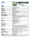
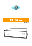
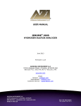
Display User's Manual
Image Systems FP1900MBNC
Multi-Resolution Analog Display
Model : GEV955IMI
Conformity according to the Council Directive 93/42/EEC concerning Medical
Devices.
Use this product after carefully reading this Manual and understanding the
contents.
Store this manual with care, as close as possible, so that you can read
whenever necessary.
Contents
1. Safety Precautions
2. Equipment Symbols
3. Cleaning Instructions
4. Disposal of the Unit
5. Connection Method
6. Adjustment Method
7. Rotating the LCD Panel
8. Compatible Signals
9. Specifications
10. Accessories
11. Power Management
12. Contact Information
1
4
6
8
9
13
14
32
33
34
35
36
Revision History
The revision letter changes with related comments each time the document is updated.
Revision
Comment
Date
A
Initial release of this document
Jan 09, 2012
B
Add power management
Jan 19, 2012
C
To increase the key lock function
Jun 18, 2012
Safety Precautions
I CAUTION
Symbol Description
Caution!-This symbol alerts you to important operating
considerations or a potential operating condition that
could damage equipment. Refer to user's manual or
operation's manual for precautionary instructions.
II CLASSIFICATION
MEDICAL EQUIPMEN T
WITH RESPECT TO ELECTRIC SHOCK,
FIRE AND MECHANICAL HAZARD S ONLY IN
ACCORDANCE WITH UL60601-1 AN D
CAN/CSA C22.2 NO.601. 1
49CG
Class I :
No applied parts
Protection against harmful ingress of water is IPX0
Not suitable for use in the presence of flammable anesthetic's or oxygen.
Mode of operation: Continuous.
III External Equipment
External equipment intended for connection to signal input / output or other connectors, shall
comply with UL/EN 60601-1 for medical electrical equipment. In addition, all such combination
system shall comply with the standard IEC 60601-1-1, Safety requirements for medical electrical
systems. Equipment not complying with UL/EN/IEC 60601-1 shall be kept outside the patient
environment, as defined on the systems standard.
IV Intended Use
The equipment is intended to be used as a component of a medical patient monitoring system.
1
V FCC
FCC Information
FCC(U. S. Federal Communications Commission)
This equipment has been tested and found to comply with the limits for a Class B digital
device, pursuant to part 15 of the FCC Rules. These limits are designed to provide reasonable
protection against harmful interference in a residential installation. This equipment generates,
uses, and can radiate radio frequency energy, and if not installed and used in accordance with
the instructions, may cause harmful interference to radio communications. However, there is
no guarantee that interference will not occur in a particular installation. If this equipment does
cause unacceptable interference to radio or television reception, which can be determined by
turning the equipment off and on, the user is encouraged to try to correct the interference by one
or more of the following measures:
● Reorient or relocate the receiving antenna.
● Increase the separation between the equipment and receiver.
● Connect the equipment into an outlet on a circuit different from that to which the receiver is connected.
● Consult your dealer or an experienced radio/TV technician for help.
FCC Warning:
To assure continued FCC compliance, the user must use a grounded power supply cord and
the provided shielded video interface cable with bonded ferrite cores. Also, any unauthorized
changes or modifications to this monitor would void the user's authority to operate this device.
VI Precautions
2
● Make sure to carefully read the Operating Manual prior to using the monitor in order to
properly use the monitor.
● Note that, excluding those cases where a responsibility for legal compensation is
recognized, the manufacturer shall bear absolutely no responsibility for damage to this
product by a customer or a third party that results from the ignoring of contents entered in
this Operating Manual and mistaken use.
● Follow the instructions below for safety use of the LCD Monitor.
- To avoid electric shock, do not attempt to remove any cover or touch the inside of the
monitor. Only a qualified service technician should open the monitor case.
- Do not insert metal objects or spill liquid into the LCD monitor through cabinet slots. They may cause accident fire, electric shock or failure. If a foreign object inserted or water
penetrated, unplug the AC cable and have the monitor serviced.
- Do not cover or block the vent holes in the case.
- Disconnect the power plug from the AC outlet if you will not use it for an indefinite period of time.
- Do not touch the screen directly with your fingers. You may damage the screen, and oil
from your skin is difficult to move.
- Do not apply pressure to the screen. The LCD is very delicate.
● If your LCD monitor uses an AC/DC Adapter: Only use the Adapter, which accompanied with this device. Use of another AC/DC Adapter may cause a malfunction or danger.
● If your LCD monitor does not operate normally-in particular, if there are any unusual
sounds or smells coming from it-unplug the AC cable immediately and contact the
manufacturer, or authorized service center.
VII Environment
- Place the monitor on a flat and leveled surface.
- Place the monitor in a well-ventilated place.
- Keep the monitor away from:
overly hot, cold or humid places, places directly under sunlight, dusty surroundings,
equipment that generate strong magnetic fields.
3
Equipment Symbols
Electrical and Electronic Equipment Symbols
In addition to the equipment symbols described in your user's manual, the following symbols
may be appear on the monitor.
Alternating current.
Direct current.
Equipotentiality. Connect device to a potential equalization conductor.
European authorized representative.
European Union Declaration of Conformity.
FCC. USA only. Complies with applicable US government (Federal Communications
Commission) radio-frequency interference regulations.
Fragile. Handle with care.
Indicates front.
Keep dry. Protect from rain.
Mercury. This product consists of devices that may contain mercury, which must be
recycled or disposed of in accordance with local, state, or country laws.
ON. Power connection to the mains.
Recycled materials or may be recycled.
Stacking limit by number.
4
Standby or power indicator.
This way up.
USB connector port.
This symbol indicates that the waste of electrical and electronic equipment must not
be disposed as unsorted municipal waste and must be collected separately. Please
contact an authorized representative of the manufacturer for information concerning
the decommissioning of your equipment
ATTENTION: Consult accompanying documents.
DANGER - Shock Hazard. Dangerous voltage. To reduce the risk of electric shock,
do not remove cover. Refer servicing to qualified service personnel.
5
Cleaning Instructions
Cleaning Instructions
Using a spray applicator, apply any of the approved liquids from the list below and use a
soft lint free cloth to clean the screen.
1. Water
2. Windex Blue (glass surfaces only)
3. Mild Soap
6
Notice:
This monitor has been adjusted specifically for use in the region to which it was originally
shipped. If the product is used outside the region, it may not operate in the specifications.
Please wait 20-40 minutes after powering on the monitor before adjusting, as it takes roughly
this same amount of time for the optimum performance of the electrical parts.
The screen may have defective pixels. These pixels may appear as slightly light or dark area on
the screen. This is due to the characteristics of the panel itself, and not the monitor.
The backlight of the LCD panel has a fixed life span. When the screen becomes dark or begins
to flicker, please contact your dealer.
Do not press on the panel or edge of the frame strongly, as this may result in the display
malfunction, such as the interference patterns, etc. If pressure is continually applied to the LCD
panel, it may deteriorate or damage your LCD panel.
Do not scratch or press on the panel with any sharp objects, such as a pencil or pen as this may
result in damage on the panel. Do not attempt to brush with tissues as this may scratch the LCD
panel.
When you bring the monitor from cold temperature room into a high temperature room or
when your room temperature goes up quickly from low to high, dew condensation may occur
inside and outside the monitor. In this case, do not turn on the monitor. Please wait till dew
condensation disappears. Otherwise it may cause some damages to the monitor.
Prolonged operation of an LCD with the same content on the same screen area may
result in a form of image retention. You can avoid or significantly reduce the occurrence
of this phenomenon by using a screen saver. You can activate a screen saver in the
“Display Properties” window of your workstation. Canvys recommends setting screen
saver activation after 5 minutes of non-usage. In case you are working with the same
image or an application with static image elements for several hours continuously (so
that the screensaver is not activated); change the image content regularly to avoid image
retention of the static elements.
Image retention is a phenomenon inherent to TFT LCD displays technology itself, and as
such, the occurrence of this “ghosting” effect is considered normal operation by the LCD glass
manufacturer. As a result, Canvys is not responsible for this damage and does not warrant
any displays against the occurrence of Image Sticking. We strongly advise that you follow the
operating recommendations listed above.
7
Disposal of the Unit
●Do not dispose of this product with general wastes.
●Follow your local regulations or rules upon dispose of this product.
●Hg WARNING
This product consists of devices that may contain mercury, which must be recycled or
disposed of in accordance with local, state, or country laws.
(Within this product, the backlight lamps in the display contain mercury.)
8
Connection Method
Confirm that your computer is off.
Then, confirm that the main switch of the LCD monitor on the back is off.
Connect the attached power cord into the inlet.
Then, connect the plug into the AC inlet on the back of the LCD monitor.
Caution
AC Main Power supply Switch
The AC main power supply switch interrupts the AC input to the display. Placing the switch
in the ON (I) position allows display to power-up, if the AC input is connected.
Placing the switch in the OFF (O) position shall cause the display to power down.
9
BNC Connector_CVBS
Composite signal input. Connect BNC cable to composite video output device.
BNC Connector_HD/CS
For two-line (Sync On Video) input, connect to CS (composite sync signal). For three-line
(separate sync signal) input, `connect to HD (horizontal sync signal).
BNC Connector_VD
For three-line (separate sync signal) input, connect to VD (vertical sync signal).
BNC Connector_Video OUT
For one-line (Sync On Video) output when Video IN input (Sync On Video) signal.
BNC Connector_Video IN
For one-line (Sync On Video) input, BNC connector is used as Sync On Video. For two-line
(VIDEO + composite sync signal) and three-line inputs, used as Video.
S-Video input connector
S-Video signal input. The attached S-Video signal cable is connected to this and an S-Video
output video device.
10
Connect Signal Cable(VGA)
Attach the VGA signal cable end, which has the ferrite core furthest away from the plug, to the
monitor and attach the other end to the graphics card adapter on your computer. Be cautious
in inserting the cable properly into both connectors. If the cable does not seem to fit it may be
facing the wrong direction. Turn the cable over and try to match the shape of the connector with
that of the graphics adapter.
11
Anti-Theft security device slot
This product has loaded an antitheft security device slot compliant with MicroSaver® Security
System of Kensington® on the back of the monochrome LCD display.
MicroSaver® security System can be purchased at PC supply shops.
®
* Kensington is a registered brand of Kensington
Antitheft security device slot
*Kensington® is a registered brand of Kensington
12
Adjustment Method
Names and Functions of Each Part
Control Dial
The Control Dial is a multi-functional device located behind the LED Indicator on the right side of
the front bezel. It has three movements-rotate upward, rotate downward and press inward as a
button.
1.Power On/Off
Press the Control Dial to power the unit on from the off stage (the LED is off). To turn the power
off, press the Control Dial and hold for at least 3 second until the LED turns off.
2.OSD Control
While the monitor is on (green LED and image on the screen), Pressing on the Control Dial
activates the OSD. While the OSD menu is active , use the three way movements of the Control
Dial to adjust the monitor.
Rotate Downward: Move Up/Right, Increase, Larger, More
Rotate Upward: Move Down/Left, Decrease, Smaller, Less
Button Press: Execute, Do, Save
LED Indicator
This LED indicator turns green when the power is switched ON and the power cord is properly
attached. It turns amber when the monitor goes into a power saving mode (Active Off).
13
Rotating the LCD Panel
When setting the color LCD display to vertical display (portrait orientation), lift the LCD panel to
the top of the tilt stand as shown in the figure below and rotate it by 90 degrees.
Procedure
1 Tilt the LCD panel upward.(Perform this procedure before sliding the panel upward.)
2 Lift the LCD panel to the top (The tilt stand will slide about 50mm).
3 Rotate the LCD panel by 90 degrees.
4 Replace the LCD panel to the bottom while in the vertical position (portrait orientation).
Display in portrait orientation
Pivot,,,
Pivot® software or graphics card that enables portrait orientation is necessary.
*Pivot® is a registered brand of Portrait Displays of the United States.
14
Mounting
The Monitor can be mounted onto the wall or stand.
If you intend to mount the monitor on the wall, we strongly recommend that you use wall mount
kits with attached M4*12mm screws and can load more than monitor weight, that you ensure it
is securely and safely installed.
CAUTION:
When mounting the monitor, take care to tighten the retention screws or bolts until fully secure,
but do not over tighten. Over tightening the retention screws or bolts may cause them to become
stripped, rendering them useless.
Wall Mounting Installation
The Monitor has Video Electronics Standards Association (VESA) standard mounting holes
tapped into the rear panel. The standard holes are M4 set at 100 mm x 100 mm apart.
To mount the Monitor onto the wall or stand, please follow the steps below.
Step 1: Select the location on the wall for the wall-mounting bracket.
Step 2: Carefully mark the locations of the four screw holes in the bracket on the wall
Step 3: Drill four pilot holes at the marked locations on the wall for the bracket retention screws.
Step 4: Align the wall-mounting bracket screw holes with the pilot holes.
Step 5: Secure the mounting-bracket to the wall by inserting the retention screws into the four
pilot holes and tightening them.
Step 6: Insert the four monitor mounting screws provided in the wall mounting kit into the four
screw holes on the real panel of the LCD Monitor and tighten until the screw shank is secured
against the rear panel.
Step 7: Align the mounting screws on the monitor rear panel with the mounting holes on the
bracket.
Step 8: Carefully insert the screws through the holes and gently pull the monitor downwards
until the monitor rests securely in the slotted holes. Ensure that all four of the mounting screws
fit snuggly into their respective slotted holes.
Step 9: Secure the LCD Monitor by fastening the retention screw of the wall-mounting bracket.
Step 10: Secure the LCD Monitor by fastening the retention screw of the wall-mounting bracket.
15
Charts of OSD Adjustment Functions
The charts displays the function tree and brief explanations of the functions. Monochrome, LCD,
and other adjustments have submenus under each tree.
● OSD display
Main menu display
• Exit• • • • • • • • • • • • • • • • • • • • • • • • • • • • • • • • • • • • • • • • • • • • • • Close the OSD screen
• Input Source Settings
Exit• • • • • • • • • • • • • • • • • • • • • • • • • • • • • • • • • • • •
Analog VGA• • • • • • • • • • • • • • • • • • • • • •
S-video• • • • • • • • • • • • • • • • • • • • • • • • • • • • • •
CVBS• • • • • • • • • • • • • • • • • • • • • • • • • • • • • • • •
Analog BNC• • • • • • • • • • • • • • • • • • • • • •
Return to Main Menu
Select Analog video input for Main channel
Select S-video video input for Main channel
Select Composite video input for Main channel
Select G, H-sync V-sync or SOG video input for Main channel
• Image Settings
Exit• • • • • • • • • • • • • • • • • • • • • • • • • • • • • • • • • • • • Return to Main Menu
Auto Setup• • • • • • • • • • • • • • • • • • • • • • • • Automatic screen size / position / brightness / contrast adjustment *1
Black Level• • • • • • • • • • • • • • • • • • • • • • • • Adjust the black level offset for the Main channel by the range from 0 to 100
Contrast• • • • • • • • • • • • • • • • • • • • • • • • • • • • Adjust the contrast for the display image by the range from 0 to 100
Saturation• • • • • • • • • • • • • • • • • • • • • • • • • Adjust the saturation for the Main channel by the range from 0 to 100
Hue• • • • • • • • • • • • • • • • • • • • • • • • • • • • • • • • • • • Adjust the hue for the Main channel by the range from 0 to 100
Sharpness• • • • • • • • • • • • • • • • • • • • • • • • • Adjust the sharpness for the Main channel by the range from 0 to 24
Display Exit• • • • • • • • • • • • • • • • • • • • • • • Return to Exit of Image Setting page
H. Position• • • • • • • • • • • Adjust horizontal screen position for Main channel
V. Position• • • • • • • • • • • • Adjust vertical screen position for Main channel
Clock• • • • • • • • • • • • • • • • • • • • Adjust the clock for the video signals for Main channel
Phase• • • • • • • • • • • • • • • • • • • Adjust the phase for the video signals for Main channel
Video Setup *2
Exit• • • • • • • • • • • • • • • • • • • • • • • • • • • • • Return to Exit of Image Setting page
Main MADI Mode• • • • • • • Motion adaptive De-interlacing that support Off / Normal / Adaptive three modes
16
Noise Reduction
•
•
•
•
•
•
•
•
•
•
•
•
•
•
•
•
•
•
•
•
•
•
•
•
•
Exit
Return to Exit of Video Setup of Image Setting page
Dynamic NR mode Dynamic NR mode that support Off / High / Medium / Low / Adaptive five modes
MPEG NR mode• • • • MPEG NR mode that support On & Off two modes
Film Mode• • • • • • • • • • • • • • • • • • Film Mode that support 3:2 & 3:2-2:2 & Off & 2:2 four modes
DCDi• • • • • • • • • • • • • • • • • • • • • • • • • • DCDi support Off & On two modes
• Color Mode Settings
Exit• • • • • • • • • • • • • • • • • • • • • • • • • • • • • • • • • • • • Return to Main Menu
Color Temp.
Exit• • • • • • • • • • • • • • • • • • • • • • • Return to Exit of Color Mode Settings page
Red Gain• • • • • • • • • • • • • User adjusts the gain of Red by the range from 0 to 100
Green Gain• • • • • • • • • • User adjusts the gain of Green by the range from 0 to 100
Blue Gain• • • • • • • • • • • • • User adjusts the gain of Blue by the range from 0 to 100
Gamma
Exit• • • • • • • • • • • • • • • • • • • • • • • Return to Exit of Color Mode Settings page
Gamma 1.8• • • • • • • • • • Set Gamma curve to curve 1.8
Gamma 2.0 *5 • • • • • • Set Gamma curve to curve 2.0
Gamma 2.2• • • • • • • • • • Set Gamma curve to curve 2.2
Gamma 2.4• • • • • • • • • • Set Gamma curve to curve 2.4
Calibration• • • • • • • • • • Calibrate monitor setting by using external device
DICOM• • • • • • • • • • • • • • • • Set Gamma curve to DICOM curve
• Management Settings
Exit• • • • • • • • • • • • • • • • • • • • • • • • • • • • • • • • • • • • Return to Main Menu
Scaling
Exit• • • • • • • • • • • • • • • • • • • • • • • Return to Exit of Management Settings page
Scaling• • • • • • • • • • • • • • • • • Support Full / Native Mode / Best Fit / Fit Width / Fit Height / Over Screen 6
modes
Zoom• • • • • • • • • • • • • • • • • • • Adjust the full size for Main channel display(Must under Full scaling mode)
Her.Zoom• • • • • • • • • • • • Adjust the H size for Main channel display (Must under Full scaling mode)
Ver.Zoom• • • • • • • • • • • • • Adjust the V size for Main channel display (Must under Full scaling mode)
Recall• • • • • • • • • • • • • • • • • • • • • • • • • • • • • • • • Initialize to the factory settings and delete the specify User setting you
saved
•
•
•
•
•
•
•
•
•
•
•
•
•
•
•
On/off ‘’Auto Adjustment’’ Function
Auto Adjustment
New Timing Search *3
Exit• • • • • • • • • • • • • • • • • • • • • • • Return to Exit of Management Settings page
Execute• • • • • • • • • • • • • • • • Execute New Timing Search that wasn’t in the preset timing table
Aspect *4• • • • • • • • • • • • • • • Adjust the display ratio of the video signals for Main channel
Clock *4• • • • • • • • • • • • • • • • Adjust the clock for the video signals for Main channel
H.Position *4• • • • • • • • • Adjust horizontal screen position for Main channel
V.postion *4• • • • • • • • • • • Adjust vertical screen position for Main channel
H size *4• • • • • • • • • • • • • • • Adjust the H size for Main channel display
V size *4• • • • • • • • • • • • • • • • Adjust the V size for Main channel display
Save Timing• • • • • • • • • There are Save & Clear for New Timing Setting
Timing Select• • • • • • • • • • • • • • • • • • • • Select Timing
17
OSD Misc. Exit• • • • • • • • • • • • • • • • • • • • • • • • • • • • • • • • • • Return To Main Menu
OSD Position
Exit• • • • • • • • • • • • • • • • • • • • • • • Return to Exit of OSD Misc.
OSD H.Position• • • Adjust the H position for OSD by the range from 0 to 100
OSD V.Position• • • • Adjust the V position for OSD by the range from 0 to 100
Language
Exit• • • • • • • • • • • • • • • • • • • • • • • Return to Exit of OSD Misc.
English *5 • • • • • • • • • • • • • Display
OSD in English
Francais• • • • • • • • • • • • • • • Display OSD in French
Deutsch• • • • • • • • • • • • • • • • Display OSD in German
Italiano• • • • • • • • • • • • • • • • • Display OSD in Italian
Espanol• • • • • • • • • • • • • • • • Display OSD in Spanish
日本語• • • • • • • • • • • • • • • • • Display OSD in Japanese
OSD Timer• • • • • • • • • • • • • • • • • • • • • • • Adjust OSD display time
Transparent• • • • • • • • • • • • • • • • • • • • • • Adjust OSD display transparent
Key Lock• • • • • • • • • • • • • • • • • • • • • • • • • • • OSD adjustment lock function
*Brightness• • • • • • • • • • • • • • • • • • • • • • • • • • • • • • • • • • • • Adjust the backlight of the full screen by the range from 0 to 100
*Notice: Brightness didn’t exist at the OSD three, adjust it by rotate up or down by wheel key
18
*1
Only VGA and BNC source
*2
Only support for S-video &CVBS
*3
This function only support on Analog VGA and BNC source
*4
This function active after press Execute
*5
For Recall (Factory defaults)
Charts of OSD Adjustment Functions
The charts displays the function tree and brief explanations of the functions. Color, LCD, and
other adjustments have submenus under each tree.
Detail of Adjustment Items
EXIT
1024 x 768
H: 48.3 KHz
V:
59.9 Hz
Timing Table : System
VIDEO
MAIN : Analog VGA
Calibration
Operation Hours : 0
Exit
Close the Main Menu.
In addition, this page will show below messages:
(1)Information for input timing of Main channel .
(2)Timing table provide by system.
(3)Indicate which source display for Main channel.
(4)Indicate which source display for Sub channel.
(5)Record how long time display for this monitor already.
Input Source Setting
You can select source for Main channel from Analog VGA , S-video , CVBS , Analog BNC .
EXIT
Input Source Settings
Exit
Analog VGA
VIDEO
S-Video
CVBS
Analog BNC
19
* Brightness
Selecting this control allows you to make adjustment to the luminance level of the display screen
by the range from 0 to 100.
Press up/down by control dial to adjust the brightness any time while the OSD is off
If the image sticking is on, must turn it off then just can let brightness work.
* Notice: Brightness didn’t exist at the OSD three, adjust it by rotate up or down by wheel key.
Image Settings
Adjust values of below items for Main channel. Beside Video Setup that only support on S-video
& CVBS.
* Notice: VideoSetup will be disable under Analog VGA or Digital or HDMI or Analog BNC
source.
EXIT
Image Settings
Exit
Auto Setup
VIDEO
Black Level
50
Contrast
50
Saturation
50
Hue
50
Sharpness
12
Display
VideoSetup
Exit
Return to Main Menu.
Auto Setup
When you press ‘’Auto Setup’’ will show ‘’Auto Adjusting’’ on the screen that do automatically
adjust the size, position, brightness, contrast and the like of the screen. When first using this
color display or input new timing will perform this adjustment. When Auto Adjusting disappears
from the screen, it means it has finished the Auto Setup function.
* Notice: Auto Setup only support on Analog VGA source and BNC source.
20
Black Level
Adjust the black level offset for the Main channel by the range from 0 to 100.
Black Level
50
Contrast
Adjust the contrast for the Main channel by the range from 0 to 100.
Saturation
Adjust the saturation for the Main channel by the range from 0 to 100.
Hue
Adjust the hue for the Main channel by the range from 0 to 100.
Sharpness
Adjust the sharpness for the Main channel by the range from 0 to 24.
Sharpness
12
21
Display
Adjust the Horizontal & Vertical position & clock & phase for Main channel.
EXIT
Image Settings
Exit
VIDEO
H.Position
50
V.Position
50
Clock
56
Phase
42
• Exit
Return to Exit of Image Setting page.
• H.Position
Adjust horizontal screen position for Main channel by the range from 0 to 100.
• V.Position
Adjust vertical screen position for Main channel by the range from 0 to 100.
• Clock
Adjust the frequency sampling rate of horizontal pixels for Main channel, to equal the video
source’s value, Thus minimizing artifacts of shimmering vertical lines.
* Notice: Only support on Analog VGA source.
• Phase
Adjust ADC sampling clock phase for Main channel, so that the screen image appear crisp and
focused.
* Notice: Only support on Analog VGA source.
22
VideoSetup
Adjust below items relate to video setting for Main channel.
* Notice: Only support for S-video & CVBS.
EXIT
Image Settings
Exit
Main MADI Mode
VIDEO
Off
Noise Reduction
Film Mode
Off
DCDi
Off
• Exit
Return to Exit of Image Setting page.
• Main MADI Mode
Motion adaptive De-interlacing that support Off & Normal & Adaptive three modes.
• Noise Reduction
This function provide Dynamic NR mode and MPEG NR mode.
EXIT
Image Settings
Exit
VIDEO
Dynamic NR Mode
Off
MPEG NR Node
Off
Exit
Return to Exit of VideoSetup of Image Setting page.
Dynamic NR mode
Dynamic NR mode that support Off & High & Medium& Low& Adaptive five modes.
MPEG NR mode
MPEG NR mode that support On & Off two modes.
• Film Mode
Film Mode that support 3:2 &3:2-2:2 & Off &2:2 four modes.
• DCDi
DCDi support Off & On two modes .
23
Color Mode Settings
Selecting this control allows you select color mode or adjust six axis for RGBYCM or RGB gain.
EXIT
Color Mode Settings
Exit
VIDEO
Color Temp.
User
Gamma
1.8
Exit
Return to Main Menu.
Color Temp.
Selecting this control allows you to adjust the Red gain , Green gain and Blue gain individually
to match personal preference.
EXIT
Color Mode Settings
Exit
VIDEO
Red Gain
50
Green Gain
50
Blue Gain
50
• Exit
Return to Exit of Color Mode Settings page.
• Red Gain
You can adjusts the gain of Red by the range from 0 to 100.
• Green Gain
You can adjusts the gain of Green by the range from 0 to 100.
• Blue Gain
You can adjusts the gain of Blue by the range from 0 to 100.
24
Gamma
Selecting this control allows you to choose which gamma curve that you want.
EXIT
Color Mode Settings
Exit
VIDEO
Gamma 1.8
Gamma 2.0
Gamma 2.2
Gamma 2.4
Calibration
DICOM
• Exit
Return to Exit of Color Mode Settings page.
• Gamma 1.8
Set Gamma curve to curve 1.8
• Gamma 2.0
Set Gamma curve to curve 2.0
• Gamma 2.2
Set Gamma curve to curve 2.2
• Gamma 2.4
Set Gamma curve to curve 2.4
• Calibration
Set Gamma curve to calibration mode.
• DICOM
Set Gamma curve for medical standards.
Management Settings
Selecting this control allows you to adjust below items settings for display image or OSD setting.
EXIT
Management Settings
Exit
VIDEO
Scaling
Recall
No
Auto Adjustment
Off
New Timing Search
Timing Select
25
Exit
Return to Main Menu.
Scaling
Support Full & Native Mode & Best Fit &Fit Width &Fit Height & Over Screen 6 modes.
EXIT
Management Settings
Exit
VIDEO
Scaling
Full
Zoom
50
Hor. Zoom
50
Ver. Zoom
50
• Exit
Return to Exit of Management Settings page.
• Zoom
Adjust the full size for display image by the range from 0 to 100.
* Notice: Support Zoom must under Full scaling mode for each source.
• Hor.Zoom
Adjust the H size for Main channel display.
* Notice: Support Her. Zoom must under Full scaling mode for each source.
• Ver.Zoom
Adjust the V size for Main channel display.
* Notice: Support Ver. Zoom must under Full scaling mode for each source.
Recall
Select this function to recall all OSD adjustments to the factory default settings and delete the
specify User setting you used.
Ex: If you load User1 from Preset Save page, the system will clear User 1 after you press ‘’recall’’
when recall is clicked which OSD items are factory reset and to what value.
Auto Adjustment
Select this function to on or off ‘’Auto Adjustment’’ Function , if you select on, when new timing
input will execute Auto Adjustment function, if you select off, when new timing input will not
26
execute Auto Adjustment function.
New Timing Search
This function will auto calculate image according to the input timing data if it wasn’t in the preset
timing table and as far as possible to display the image that close to the input new timing.
Display a dot on-dot off test pattern or full screen test pattern and press ‘’Execute’’ to get certain
display image.
If new timing search is not still available or does not give satisfactory results, proceed as follows:
1.Entry into ‘’Management Settings’’ page to adjust clock/H.position.
2.Adjust the image width fits the LCD panel width.
3.Then,press the ‘’Execute’’, use this function to search new timing again.
4.Save the several timings which have been fine tune successfully. (Refer to the details on page
17 ‘’Save Timing’’ section)
* Notice: This function only support on Analog VGA and Analog BNC source.
EXIT
Management Settings
Exit
VIDEO
Execute
No
Aspect
1:1
Colck
1331
H.Position
50
V.Position
50
H Size
50
50
V Size
• Exit
Save Timing
Off
Return to Exit of Management Settings page.
• Execute
Execute New Timing Search that wasn’t in the preset timing table.
• Aspect
Adjust the display ratio of the video signals for Main channel. (active after press Execute; default
was disable this function)
• Clock
Adjust the clock for the video signals for Main channel. (active after press Execute; default was
disable this function)
• H.Position
Adjust horizontal screen position for Main channel. (active after press Execute; default was
disable this function)
• V.Position
Adjust vertical screen position for Main channel. (active after press Execute; default was disable
this function)
27
• Save Timing
There are Save & Clear for New Timing Setting.
If the user makes any additional adjustment, the video signal (with its adjustments) can be
stored as user mode.
The next time this video signal is connected and selected , the display recognizes it as one of
the user modes and reproduces it with the corresponding adjustments. The signal is recognized
by its timing and the type of video input it is connected to. This means a certain video signal
connected to the VGA or BNC can be stored as two different user modes.
The display memory can contain maximum 16 different users modes. When the memory is full,
user can use ‘’clear timing’’ to clear some of the 16 modes when a new video signal is adjusted.
You can save the new timing after you press Execute, totally can save sixteen timings.
1. Choose save and entry into ‘’Save timing’’ page.
EXIT
Save Timing
Exit
VIDEO
2. Move to blank place then press enter you will see below photo and select ‘’Yes’’ to enter.
Correct save timing data?
No
28
Yes
3. You will see the new timing have stored in the system and show on the ‘’Save timing’’ page.
EXIT
Save Timing
Exit
VIDEO
You also can clear the new timing after you save.
1. Choose clear and entry into the ‘’Clear timing’’ page.
EXIT
Clear Timing
Exit
VIDEO
2. Move to the timing that you want to clear then press enter you will see below photo and select
‘’Yes’’ to enter.
Correct clear timing data?
No
Yes
3. You will see the new timing have cleared from the ‘’Clear timing’’ page.
EXIT
Clear Timing
Exit
VIDEO
29
Timing Select
Select this function to select timing.
OSD Misc.
Selecting this control allows you to adjust below items settings for OSD.
EXIT
OSD Misc.
Exit
VIDEO
OSD Position
Language
OSD Timer
10
Transparent
0
Exit
Return to Main Menu.
OSD Position
Selecting this control allows you to adjust position for OSD.
EXIT
OSD Misc.
Exit
VIDEO
OSD H.Position
50
OSD V.Position
50
• Exit
Return to Exit of OSD Misc.
• OSD H.Position
Adjust the H position for OSD by the range from 0 to 100.
• OSD V.Position
Adjust the V position for OSD by the range from 0 to 100.
30
Language
Selecting this control allows you to choose below languages that you want to display for OSD.
EXIT
OSD Misc.
Exit
VIDEO
English
Francais
Deutsch
ltaliano
Espanol
• Exit
Return to Exit of OSD Misc.
• English
Display OSD in English.
• Francais
Display OSD in French.
• Deutsch
Display OSD in German.
• Italiano
Display OSD in Italian.
~
• Espanol
Display OSD in Spanish.
• 日本語
Display OSD in Japanese.
OSD Timer
Adjust OSD display time that support 5 & 10 & 15 & 20 & 25 & 30
OSD will not disappear if set to 5.
OSD will disappear after 5 sec if set to 5 (just like that for 10 & 15 & 20 & 25 & 30)
Transparent
Adjust OSD display transparent from 0 to 7 by one step.
Key Lock
OSD adjustment lock function.
31
Compatible Signals
1.Applicable Signals Timings
※The display may not work correctly with timings other than listed below.
◎ : Recommended timing
Display mode
VESA
○ : Applied timing
Resolution
Frequency
Horizontal Vertical
(kHz)
(Hz)
37.9
72
19"
Horizontal
Vertical
640
480
640
480
37.5
75
○
640
480
43.3
85
○
800
600
35.1
56
○
800
600
37.9
60
○
800
600
48.1
72
○
800
600
46.9
75
○
800
600
53.7
85
○
1024
768
48.4
60
○
1024
768
56.5
70
○
1024
768
60.0
75
○
1024
768
68.7
85
○
1280
1024
64.0
60
◎
1280
1024
80.0
75
○
○
※A large number of additional custom timings have been added. Contact Canvys for details.
32
Specifications
Product name :19" Monochrome LCD Display
Specifications
Items
LCD display device
49cm (19inch)Monochrome TFT Normally Black
Pixel pitch
Horizontal 0.294mm x Vertical 0.294mm
Display area
Horizontal 376.3mm x Vertical 301.1mm
Pixel
1280 x 1024 pixels
Supported Grayscale
8-bit per 1, sub-pixel
Standard viewing
angle
Horizontal : 170 deg.
Input signal
(1) VGA Connector
(2) S-Video Connector
(3) BNC Connector
Video-In: 0.7Vp-p/75 ohm (Sync On Green, 0.3Vp-p sync negative)
HD/CS: Horizontal sync, TTL level / CS sync input
VD: Vertical sync, TTL level input
CVBS: Composite Signal input (0.714 Vp-p / 75 ohm, NTSC / PAL / SECAM)
Output signal: BNC Connector x 1
Temperature
Vertical : 170 deg.
Operation
Temperature
: 10~40°C
Humidity(non-condensation) : 30~75%
Air pressure
: 700~1060hPa
Storage
-20~60°C
10~90%
500~1060hPa
Power Supply
AC100~240V, 50/60Hz, 1.2-0.9A
Consumption current
Approx.80W Max./ Less than 8W when power management on.
External dimensions
Width 432mm x Depth 251mm x Height 467mm(landscape).
Mass
Approx.8.1kg (net weight)
International standards
UL/cUL, FCC-B, CE
External Dimensions
Landscape(longer side at the top)
33
Accessories
1. US Power cord
2. VGA cable
3. S-Video cable
34
Power Management
This Power Management System helps you to save energy by switching your monitor into a
low-power consumption mode when it has not been used for a certain period of time. Power
Management System operates with VESA DPMS compliant video card installed in your
Workstation. Canvys highly recommends setting DPMS to activate after 15 minutes of nonusage in order to optimize your displays lifetime and to avoid Image retention damage. We
also recommend users:
Not to leave the same image or viewing frame too long in one position.
Frequently changing and moving of image and viewing frame will help to avoid Image Retention
(also called “Image Sticky”). Image Retention is a phenomenon inherent to TFT LCD display
technology itself, and as such, the occurrence of this “Ghosting” effect is considered normal
operation by all LCD glass manufacturers. As a result, Canvys is not responsible for this damage
& does not warrant any displays against the occurrence of Image Sticking. We strongly advise
that you follow the operating recommendations listed above.
35
Contact Information
1.Contact Information:
Technical Support and Sales – Contact CanvysTekLink via:
TekLink Website at (http://teklink.canvys.com)
Support Phone Toll Free at (800) 235-2125
Sales Phone Toll Free at (888) 735-7373
Manufactured for Canvys by DIVA Laboratories Ltd, Taiwan.
2.Copyright Notice
This document is copyrighted. All rights are reserved. Neither this document, nor any part
of it, may be reproduced or copied in any form or by any means-graphical, electronic, or
mechanical including photocopying, taping or information storage and retrieval systems
without written permission of Canvys a division of Richardson Electronics
© 2012 Canvys a division of Richardson Electronics. All rights reserved.
Consult your dealer for technlcal support.
36
MDLP9PR01B