1
MINUTEMAN™
MINUTEMAN
3D TRACKER
USER MANUAL
URM06PH191
REV. A – FEBRUARY 2008
MINUTEMAN MANUAL
{This page intentionally left blank.}
MINUTEMAN MANUAL
Copyright© 2006 by Alken, Inc., dba Polhemus
Colchester, Vermont, U.S.A.
All rights reserved. No part of this publication may be reproduced, stored in a retrieval system, or
transmitted, in any form or by any means, mechanical, photocopying, recording or otherwise, without the
prior written permission of Polhemus. No patent liability is assumed with respect to the use of the
information contained herein. While every precaution has been taken in the preparation of this manual,
Polhemus assumes no responsibility for errors or omissions. Neither is any liability assumed for damages
resulting from use of the information contained herein.
MINUTEMAN™ is a trademark of Polhemus.
Windows® is a registered trademark of Microsoft Corporation.
FCC Statement
This equipment has been tested and found to comply with the limits for a Class B digital device, pursuant to part 15
of the FCC Rules. These limits are designed to provide reasonable protection against harmful interference in a
residential installation. This equipment generates uses and can radiate radio frequency energy and, if not installed
and used in accordance with the instructions, may cause harmful interference to radio communications. However,
there is no guarantee that interference will not occur in a particular installation. If this equipment does cause harmful
interference to radio or television reception, which can be determined by turning the equipment off and on, the user
is encouraged to try to correct the interference by one or more of the following measures:
• Reorient or relocate the receiving antenna.
• Increase the separation between the equipment and receiver.
• Connect the equipment into an outlet on a circuit different from that to which the receiver is connected.
• Consult the dealer or an experienced radio/TV technician for help.
EC – Declaration of Incorporation
This Product Complies with the following European Community Directives:
89/336/EEC as amended by 92/31/EEC
The following standards were used to verify compliance with the directives:
EMC:
EN 61326-1:1997 / A1:1998 / A2:2001 / A3:2003 Emissions Requirements Class B, Radiated Emissions
EN 61326-1:1997 / A1:1998 / A2:2001 / A3:2003 Immunity Requirements
EN 61000-4-2:1995 (ESD 4kV CD, 8kV AD)
EN 61000-4-3:2002 / A1:2002 (3V/m 80% AM)
REV. A
i
FEBRUARY 2008
MINUTEMAN MANUAL
{This page intentionally left blank.}
REV. A
ii
FEBRUARY 2008
MINUTEMAN MANUAL
TABLE OF CONTENTS
TABLE OF FIGURES................................................................................................................... iv
Welcome ......................................................................................................................................... 1
Components ................................................................................................................................ 1
Initial MINUTEMAN Setup and System Test................................................................................ 2
1.
Install the MINUTEMAN Host Software........................................................................... 2
2.
Connect sensors to the MINUTEMAN E-Pod.................................................................... 2
3.
Connect MINUTEMAN E-Pod to Host USB..................................................................... 3
4.
Verify MINUTEMAN Hardware. ...................................................................................... 5
5.
Verify MINUTEMAN Function and Host Software. ......................................................... 5
Operational Installation................................................................................................................... 7
Location and Mounting............................................................................................................... 7
Coordinate Reference ................................................................................................................. 9
Multiple MINUTEMAN Systems Installation.............................................................................. 11
1.
Operating Frequency......................................................................................................... 11
2.
USB Power........................................................................................................................ 11
3.
Coordinate System ............................................................................................................ 11
MINUTEMAN Configuration ...................................................................................................... 12
Output Orientation Format........................................................................................................ 12
•
Euler Angles (default)................................................................................................... 12
•
Direction Cosines.......................................................................................................... 12
•
Orientation Quaternion ................................................................................................. 12
Boresight................................................................................................................................... 14
Host Prediction ......................................................................................................................... 15
Filtering..................................................................................................................................... 16
Electronic Stabilization Process (ESP) ..................................................................................... 17
Soft Reset.................................................................................................................................. 18
MINUTEMAN Host Software...................................................................................................... 19
PiMgr Tracker Management Application ................................................................................. 19
Polhemus Developer Interface SDK......................................................................................... 19
REV. A
iii
FEBRUARY 2008
MINUTEMAN MANUAL
TABLE OF FIGURES
Figure 1 MINUTEMAN Components ............................................................................................ 1
Figure 2 MINUTEMAN E-Pod ...................................................................................................... 3
Figure 3 “Found New Hardware” Screen ....................................................................................... 4
Figure 4 USB Serial Port “Found New Hardware” Screen ............................................................ 4
Figure 5 PI Tracker Config Screen ................................................................................................. 5
Figure 6 Sensor Orientation Data Collection Screen...................................................................... 6
Figure 7 E-Pod screw mount........................................................................................................... 7
Figure 8 E-Pod mounted on tripod.................................................................................................. 7
Figure 9 Sensor Mounting Flanges ................................................................................................. 8
Figure 10 E-Pod Reference Diagram.............................................................................................. 9
Figure 11 Sensor Reference Diagram ............................................................................................. 9
Figure 12 “Right-Hand” Rule ......................................................................................................... 9
Figure 13 Coordinate Reference System ...................................................................................... 10
Figure 14 Sensor Aligned with E-Pod .......................................................................................... 10
Figure 15 Configure Output Orientation Format .......................................................................... 13
Figure 16 Configure Sensor Boresight ......................................................................................... 14
Figure 17 Configure Host Prediction............................................................................................ 15
Figure 18 Configure Filter ............................................................................................................ 16
Figure 19 Soft Reset...................................................................................................................... 18
REV. A
iv
FEBRUARY 2008
MINUTEMAN MANUAL
Welcome
Thank you for purchasing the highest performance, lowest cost, best value tracker on the planet!
The following will acquaint you with the components of the system, how to connect it, and how
to set it up for your application.
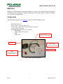
Components
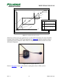
The following components (see Figure 1) make up a MINUTEMAN system.
-
MINUTEMAN E-Pod
Sensor with two nylon mounting screws
6 foot (2 meter) sensor cable with 6 pin modular connectors
17 foot (5 meter) USB cable
MINUTEMAN Host Software CD containing:
o This manual
o PiMgr graphical user interface
o SDK
o USB drivers
USB Cable
17 foot (5 meter) length
E-Pod
Sensor Cable
6 foot (2 meter) length
Host Software CD
Sensor
with nylon screws and
mounting flanges
Figure 1 MINUTEMAN Components
REV. A
1
FEBRUARY 2008
MINUTEMAN MANUAL
Initial MINUTEMAN Setup and System Test
Follow these set-up and connection steps to demonstrate basic operation of your MINUTEMAN
system.
Caution: Do not connect the USB cable until instructed.
1. Install the MINUTEMAN Host Software.
i. Insert the MINUTEMAN Host Software CD into your computer’s CD-ROM
drive. If your system is configured for CD auto-launch, the MINUTEMAN Host
Software installation panel will launch automatically. If it does not, launch the
panel manually by navigating to the CD-ROM drive using Windows Explorer.
Run “Setup.exe”.
ii. Click on the area labeled “Install Host Software.” The installation wizard will
walk you through the installation.
iii. Leave the CD in the CD-ROM drive for USB device installation.
NOTE: The MINUTEMAN Host Software is intended to be installed on a computer running
Windows® XP, 2000 and Vista only.
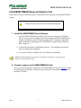
2. Connect sensors to the MINUTEMAN E-Pod.
One or more sensors must be connected to the MINUTEMAN E-Pod (see Figure 2) prior
to connecting the USB cable. Connect sensor(s) with the six-pin modular connectors on
the black 2 M cable.
REV. A
2
FEBRUARY 2008
MINUTEMAN MANUAL
Figure 2 MINUTEMAN E-Pod
NOTE: The six-pin modular sensor cable is readily available in the marketplace should more
length be required. However, a substitute sensor cable must not exceed 14 ft (4.25 m) and must
be wired straight through both connectors, male-male.
3. Connect MINUTEMAN E-Pod to Host USB.
NOTE: MINUTEMAN gets its operating power through the USB connection. If you are
using a USB hub that does not provide the full USB power allotment, the E-Pod will not
operate!
When the USB cable is connected to the host PC for the first time, Windows will detect
the new hardware and launch the device driver installation wizard. The MINUTEMAN
driver installation is slightly more complex than most USB devices because the drivers
are installed in two steps:
i. First Windows will detect and install the MINUTEMAN drivers. The “Found
New Hardware” bubble will appear in the Windows taskbar:
REV. A
3
FEBRUARY 2008
MINUTEMAN MANUAL
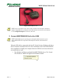
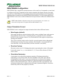
Windows will automatically launch the Found New Hardware Wizard (see Figure
3), which will walk you through the driver installation procedure. If your
MINUTEMAN Host Software CD is not in the CD-ROM drive, insert it now.
Select “Install the software automatically” and click “Next”:
Figure 3 “Found New Hardware” Screen
Click on the “Finish” button when the driver installation is complete.
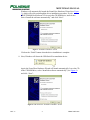
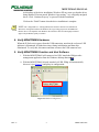
ii. Next, Windows will detect the USB-Serial Port emulation device:
Again, the Found New Hardware Wizard will launch automatically. Leave the CD
in the CD-ROM drive, select “Install the software automatically” (see Figure 4)
and click “Next”:
Figure 4 USB Serial Port “Found New Hardware” Screen
REV. A
4
FEBRUARY 2008
MINUTEMAN MANUAL
At this phase of the driver installation, Windows XP may warn you that the driver
being installed “Has not passed Windows Logo testing,” or is a digitally unsigned
driver. Click “Continue Anyway” to proceed with the installation.
Click on the “Finish” button when the driver installation is complete.
NOTE: The “unsigned driver” warning indicates that the driver has not been submitted to
Microsoft's "Designed for Microsoft Windows XP" logo testing program. It does not mean
that the driver is incompatible with Windows XP. This driver has been thoroughly tested and
approved by Polhemus Quality Assurance.
4. Verify MINUTEMAN Hardware.
When the E-Pod receives power from the USB connection, note that the red power LED
indicator is illuminated. It blinks three times during initialization and then stays
illuminated. To verify this, disconnect and then reconnect the USB connector now.
5. Verify MINUTEMAN Function and Host Software.
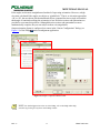
i. With the MINUTEMAN still connected via USB, launch the PiMgr tracker
management application from the Windows desktop shortcut .
ii. With the MINUTEMAN already attached via USB, PiMgr will automatically
discover it (see Figure 5) and query its configuration:
Figure 5 PI Tracker Config Screen
REV. A
5
FEBRUARY 2008
MINUTEMAN MANUAL
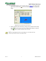
iii. Collect MINUTEMAN sensor orientation data (see Figure 6) by clicking on the
. Note the orientation of the sensor displayed by
single frame toolbar button
PiMgr:
Figure 6 Sensor Orientation Data Collection Screen
iv. Initiate continuous data collection by clicking on the continuous mode toolbar
button
. Move the sensor to note that orientation data changes as expected.
again to suspend continuous data collection.
Click
NOTE: For detailed instruction on the use of the PiMgr, refer to the PiMgr online help,
accessible by pressing F1 anywhere on the PiMgr window.
REV. A
6
FEBRUARY 2008
MINUTEMAN MANUAL
Operational Installation
Location and Mounting
Set up MINUTEMAN close to your host computer and away from large metal objects like file
cabinets, metal desks, etc., and away from the floor and walls. Also, it is important to position
the system so that the working area for your application is centered in the 36 inch/90 cm radial
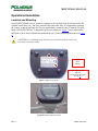
range of the MINUTEMAN. A standard tripod screw mount (see Figure 7) is provided on the
underside of the E-Pod. Polhemus recommends the use of a non-metal tripod mount (see Figure
8).
CAUTION: To avoid damage to the electronics, do not force the tripod screw after it has
been firmly seated in the mount.
Tripod
Screw
Mount
Operating Frequency
Indicator
(see Operating Frequency
on page 11)
Figure 7 E-Pod screw mount
Figure 8 E-Pod mounted on tripod
REV. A
7
FEBRUARY 2008
MINUTEMAN MANUAL
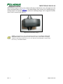
MINUTEMAN sensors can be screwed down with the provided nylon screws through slots in the
sensor mounting flanges (see Figure 9). The slotted flanges allow sensors to be installed into preexisting fixtures. If a smaller footprint is needed, the mounting flanges can be clipped off and the
sensor can be mounted with adhesive.
Figure 9 Sensor Mounting Flanges
NOTE: Nylon hardware is only required when the hardware will be in direct contact with
the E-Pod or sensor. A testing surface where the devices will be used (a table, for example,
could have small metal hardware like screws, nuts, and bolts, which probably would not affect
the accuracy of the MINUTEMAN..
REV. A
8
FEBRUARY 2008
MINUTEMAN MANUAL
Coordinate Reference
Reference diagrams are printed on the top of the E-Pod (see Figure 10) and on the sides of the
sensor (see Figure 11). MINUTEMAN orientation tracking occurs according to the “right-hand”
rule (see Figure 12) with reference to these markings. To demonstrate the “right-hand” rule point
the index finger of your right hand along the desired reference frame Y-axis with your palm
facing the Z-axis; your thumb will point to the X-axis
Figure 10 E-Pod Reference Diagram
Figure 11 Sensor Reference Diagram
Figure 12 “Right-Hand” Rule
The sensor’s Azimuth, Elevation, and Roll (AER) angles are based on this orientation. Both the
sensor and the E-Pod (source) have these orientation coordinates. By default, the E-Pod is the
reference, with an orientation of (0, 0, 0) AER. The measured AER of each sensor is relative to
the E-Pod. In a typical installation, the E-Pod is installed in alignment with the natural
coordinates of the environment (see Figure 13), and the sensors are then referenced to those
coordinates.
NOTE: Euler angles Azimuth, Elevation, and Roll (AER), are also known as “Yaw,”
“Pitch” and “Roll.” This is the default form in which MINUTEMAN reports sensor orientation.
See the section entitled “Output Orientation Format” for more information.
REV. A
9
FEBRUARY 2008
MINUTEMAN MANUAL
Z
Z
Sensor
Orientation
Y
ρ
θ
ψ
P
R
Y
Sensor
Coord. Ref.
ρ
z
y
θ
ψ
Source
X
Legend:
in the horizontal X-Y
ψ azimuth,
plane
θ
elevation, from the X-Y plane
ρ
roll, about the vector from the
source to the sensor being
tracked
X
x
Figure 13 Coordinate Reference System
Should you wish to start your application at a (0,0,0) AER orientation, the sensor should be
brought in line with the E-Pod X-axis indicated (see Figure 14) and then rotated to achieve
approximately that orientation. MINUTEMAN components should be mounted to fix this
mechanical alignment.
Figure 14 Sensor Aligned with E-Pod
Refer to Boresight on page 14 for details on setting the relative AER to (0,0,0).
REV. A
10
FEBRUARY 2008
MINUTEMAN MANUAL
Multiple MINUTEMAN Systems Installation
Wherever multiple MINUTEMAN E-Pods are to be employed it is important to note the
following:
1. Operating Frequency
Four different operating frequencies allow up to four E-Pods to operate in the same
environment without interfering with each other. The operating frequency of each
MINUTEMAN is denoted by a colored dot on the E-Pod (see Figure 7). The colors and
frequencies are:
30 KHz – Yellow (Standard)
33 KHz – Black
28.5 KHz – Red
31.5 KHz - Blue
CAUTION: If multiple E-Pods are to be used together, care must be taken to ensure that
when ordering the second, third and fourth MINUTEMAN E-Pods, each operates at a different
frequency.
2. USB Power
Use the native USB port or a powered hub to operate the MINUTEMAN E-Pod. A USB
expansion hub typically does not provide such power.
3. Coordinate System
In most multi-E-Pod environments, all E-Pods will be aligned to the same coordinate
system.
To accomplish this, E-Pods could be placed side-by-side on a tripod extension bar and
pointed in the same direction. Sensor mountings for each E-Pod system should also be
identical to achieve the same orientation reference. Each E-Pod defines the reference
system for the sensor(s) connected to it. If multiple E-Pods are in use, be aware of the
possible need to harmonize or align the E-Pod reference frames, either mechanically or
mathematically.
NOTE: When mounting E-Pods side-by-side, keep them spaced at least 6 inches (16 cm)
apart.
REV. A
11
FEBRUARY 2008
MINUTEMAN MANUAL
MINUTEMAN Configuration
MINUTEMAN has a simplified command structure with a small set of commands to control and
to configure the E-Pod. Commands include output orientation data format, filtering, boresight,
and soft reset. MINUTEMAN can be managed entirely through the PiMgr tracker management
application that is included on the MINUTEMAN Host Software CD. For custom applications,
MINUTEMAN can be driven with the Polhemus Developer Interface SDK, also included on the
CD.
NOTE: MINUTEMAN configuration settings do not persist through any soft- or hard- reset
of the E-Pod. Settings must be re-applied each time MINUTEMAN is reset.
Output Orientation Format
MINUTEMAN can be configured to output orientation data in three different formats:
• Euler Angles (default)
Euler angles define the current orientation of the sensor coordinate frame with respect to
the designated reference frame, commonly known as Azimuth, Elevation, and Roll
(AER), or in the aerospace context, Yaw, Pitch and Roll. Euler angles are expressed as
floating-point numbers.
They refer to the three angles used to describe a general rotation in three-dimensional
Euclidean space by three successive rotations, once about the z-axis (Azimuth/Yaw),
once about the y-axis (Elevation/Pitch), and once about the x-axis (Roll).
• Direction Cosines
Direction cosines are a 3x3 floating-point matrix representing the cosines of the angles
between the sensor’s x-, y-, z-axes and the X-, Y-, Z-axes of the reference (E-Pod or
source) frame.
• Orientation Quaternion
A quaternion is an ordered four-parameter quantity of floating-point numbers
representing a vector and a scalar. The first coordinate is the 'scalar' part, and the
remaining three make up the 'vector' part. Quaternions are often used in computer
graphics and associated geometric analysis to represent rotations and orientations of
objects in three-dimensional space. They are smaller than other representations, and
operations on them can be computed more efficiently. Quaternion algebra is also more
numerically stable for this purpose (see below).
REV. A
12
FEBRUARY 2008
MINUTEMAN MANUAL
Euler angles are the most straightforward method of expressing orientation. However, at high
elevation, calculated Euler angles are subject to “gimbal lock.” That is, as elevation approaches
+90º or -90º, the axes about which azimuth and roll are computed become a single axis and the
third angle of rotation describing the orientation is lost. Direction cosines and quaternions are
provided to overcome this problem. Although direction cosines and quaternions are more
mathematically complex, they are not subject to these axis singularities.
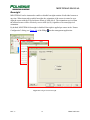
Output orientation format is configured per sensor in the “Sensor Configuration” dialog (see
Figure 15) of the PiMgr tracker management application:
Figure 15 Configure Output Orientation Format
NOTE: For detailed instruction on the use of the PiMgr, refer to the PiMgr online help,
accessible by pressing F1 anywhere on the PiMgr window.
REV. A
13
FEBRUARY 2008
MINUTEMAN MANUAL
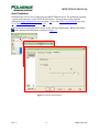
Boresight
MINUTEMAN can be instructed to enable or disable boresight rotation of individual sensors at
any time. When instructed to enable boresight, the orientation of the sensor is rotated so as to
align the sensor with the E-Pod reference frame of AER (0,0,0). The orientation received from
the affected sensor will be effectively reset to AER (0,0,0), regardless of its actual physical
orientation.
By default, MINUTEMAN boresight is disabled. Boresight is applied per sensor in the “Sensor
Configuration” dialog (see Figure 16) of the PiMgr tracker management application:
Figure 16 Configure Sensor Boresight
REV. A
14
FEBRUARY 2008
MINUTEMAN MANUAL
Host Prediction
Prediction up to 50 ms can be enabled for each MINUTEMAN sensor. The prediction operation
is performed on the host, not the MINUTEMAN device. This operation requires that the
configured Output Orientation Format (see page 12) be either Euler Angles (default) (see page
12) or Orientation Quaternion (see page 12).
Host Prediction is configured per the sensor in the “Sensor Configuration” dialog of the PiMgr
tracker management application, as shown in Figure 17:
Figure 17 Configure Host Prediction
REV. A
15
FEBRUARY 2008
MINUTEMAN MANUAL
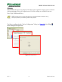
Filtering
MINUTEMAN incorporates an adaptive filter that provides significant output (“jitter”) reduction
while maintaining good overall responsiveness. Four filter settings are available to the user:
None, Light, Medium and Heavy.
NOTE: Filtering does not change the update rate of the MINUTEMAN. Medium to heavy
filtering may produce perceivable lag in the tracking outputs.
The filter is configured in the “Tracker Configuration” dialog (see Figure 18) of the PiMgr
tracker management application:
Figure 18 Configure Filter
REV. A
16
FEBRUARY 2008
MINUTEMAN MANUAL
Electronic Stabilization Process (ESP)
The ESP is an innovative adaptive filtering process that analyzes tracker signal noise/jitter and
automatically adjusts its acceptance “windows” to smooth the orientation output prior to
reporting to the host. This is done dynamically inside the MINUTEMAN processor code while
the DSP is analyzing the data variability. ESP provides stabilization over the range of tracker
application that outperforms typical adaptive filtering and has the effect of increasing tracker
range over larger sensor/E-Pod separation distances. Highest resolutions are attained at close
range. Refer to online help for disabling details.
REV. A
17
FEBRUARY 2008
MINUTEMAN MANUAL
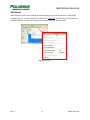
Soft Reset
MINUTEMAN can be reset without disconnecting the power/USB connection via the PiMgr
“Initialize Device” selection in the Tools Menu (see Figure 19). Note that any soft or hard reset
to MINUTEMAN will reset all configuration settings to factory default values.
Figure 19 Soft Reset
REV. A
18
FEBRUARY 2008
MINUTEMAN MANUAL
MINUTEMAN Host Software
The MINUTEMAN Host Software set is found on the MINUTEMAN Host Software CD. See
Initial MINUTEMAN Setup and System Test on page 2 for instructions on installing this
software.
PiMgr Tracker Management Application
The PiMgr application is capable of managing every aspect of MINUTEMAN configuration and
control. It may be used on its own to troubleshoot the E-Pod, and to collect, record, save and play
back motion data.
PiMgr is launched with the PiMgr desktop and quick launch icons
ProgramsÄPolhemus Windows menu.
, or from the StartÄAll
Detailed instruction on the use of PiMgr features can be found in PiMgr’s online help program,
accessed through the application’s main Help menu, the “What’s This?” toolbar button
, or
by pressing F1 anywhere in the PiMgr window.
Polhemus Developer Interface SDK
For custom applications, the Polhemus Developer Interface (PDI) is available on the CD. This is
a C++ programming library complete with sample projects and online help. For detailed
instructions on the use of the PDI, refer to the PDI online help program. Launch the PDI online
help with the desktop or quick launch icon.
REV. A
19
FEBRUARY 2008
MINUTEMAN MANUAL
APPENDIX A. Limited Warranty and Limitation of Liability
Manufacturer warrants that the Product shall be free from defects in material and workmanship
for a period of two years from the date of Manufacturer’s delivery to the Buyer, or two years and
30 days from the date ownership of Product passed to the Buyer, whichever occurs first, with the
exception of FastSCAN, which has a warranty period of only one year. Manufacturer shall, upon
notification within the warranty period, correct such defects by repair or replacement with a like
serviceable item at Manufacturer's option. This warranty shall be considered void if the Product
is operated other than in accordance with the instructions in Manufacturer's User Manual or is
damaged by accident or mishandling. Parts or material which are disposable or expendable or
subject to normal wear beyond usefulness within the warranty period such as lamps, fuses,
batteries, etc., are not covered by this warranty.
In the event any Product or portion thereof is defective, Buyer shall promptly, and within the
warranty period, notify Manufacturer in writing of the nature of the defect and return the
defective parts to Manufacturer at the direction of Manufacturer’s Customer Service
representative. Upon determination by Manufacturer that the parts or Products are defective and
covered by the warranty set forth above, Manufacturer, at its option shall repair or replace the
same without cost to Buyer. Buyer shall be responsible for any import/export duties/tariffs and
pay all charges for transportation and delivery costs to Manufacturer's factory for defective parts
where directed to be sent to Manufacturer, and Manufacturer shall pay for transportation costs to
Buyer's facility only for warranty replacement parts and Products. Removed parts covered by
claims under this warranty shall become the property of Manufacturer.
In the event that allegedly defective parts are found not to be defective, or not covered by
warranty, Buyer agrees that Manufacturer may invoice Buyer for all reasonable expenses
incurred in inspecting, testing, repairing and returning the Products and that Buyer will pay such
costs on being invoiced therefor. Buyer shall bear the risk of loss or damage during transit in all
cases.
Any repaired or replaced part or Product shall be warranted for the remaining period of the
original warranty or thirty (30) days, whichever is longer.
Warranties shall not apply to any Products which have been:
repaired or altered other than by Manufacturer, except when so authorized in writing by
Manufacturer; or
used in an unauthorized or improper manner, or without following normal operating
procedures; or
improperly maintained and where such activities in Manufacturer's sole judgment, have
adversely affected the Products. Neither shall warranties apply in the case of damage
through accidents or acts of nature such as flood, earthquake, lightning, tornado, typhoon,
power surge(s) or failure(s), environmental extremes or other external causes. Warranties
shall not apply to any Products if the Products are defective because of normal wear and
tear; or
used for any purpose without obtaining any applicable regulatory approvals.
REV. A
A-1
FEBRUARY 2008
MINUTEMAN MANUAL
MANUFACTURER DOES NOT WARRANT AND SPECIFICALLY DISCLAIMS THE
WARRANTY OF MERCHANTABILITY OF THE PRODUCTS OR THE WARRANTY OF
FITNESS OF THE PRODUCTS FOR ANY PARTICULAR PURPOSE. MANUFACTURER
MAKES NO WARRANTIES, EXPRESS OR IMPLIED, EXCEPT OF TITLE AND AGAINST
PATENT INFRINGEMENT, OTHER THAN THOSE SPECIFICALLY SET FORTH HEREIN.
IN NO EVENT SHALL MANUFACTURER BE LIABLE UNDER ANY CIRCUMSTANCES
FOR SPECIAL INCIDENTAL OR CONSEQUENTIAL DAMAGES, INCLUDING, BUT NOT
LIMITED TO LOSS OF PROFITS OR REVENUE. WITHOUT LIMITING THE FOREGOING
MANUFACTURER'S MAXIMUM LIABILITY FOR DAMAGES FOR ANY CAUSE
WHATSOEVER, EXCLUSIVE OF CLAIMS FOR PATENT INFRINGEMENT AND
REGARDLESS OF THE FORM OF THE ACTION (INCLUDING BUT NOT LIMITED TO
CONTRACT NEGLIGENCE OR STRICT LIABILITY) SHALL BE LIMITED TO BUYER'S
ACTUAL DIRECT DAMAGES, NOT TO EXCEED THE PRICE OF THE GOODS UPON
WHICH SUCH LIABILITY IS BASED.
The Products are not certified for medical or bio-medical use. Any references to medical or biomedical use are examples of what medical companies have done with the Products after
obtaining all necessary or appropriate medical certifications. The end user/OEM/VAR must
comply with all pertinent FDA/CE and all other regulatory requirements.
REV. A
A-2
FEBRUARY 2008
MINUTEMAN MANUAL
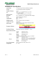
APPENDIX B. Specifications
Update Rate
Latency
Number of Sensors
I/O
Static Accuracy
Resolution
Range
Angular Rate
Multiple Systems
Angular Coverage
Data Format
75 Hz per sensor (fixed), simultaneous samples
2 ms (OS and Host Software dependent)
1 or 2
USB 1.1 or 2.0, WinXP/2K driver provided
17-ft. cable supplied
< 2° RMS orientation accuracy at 24 inches
0.01° orientation (at 12”, using default filter settings)
Approximately 36 in. (90 cm)
Max: Unlimited
Min: 0
Up to 4 systems in same environment
All-attitude
IEEE 754 binary; Euler Angles, Direction Cosines,
Orientation Quaternion
30 KHz – Yellow (Standard)
33 KHz – Black
28.5 KHz – Red
31.5 KHz– Blue
Frequency Indicator
Proprietary, host-driven, adjustable 1 – 50 ms.
Prediction Filtering
Physical Characteristics
Length:
3.00 inch (7.6cm)
Width:
4.00 inch (10.2cm)
Height:
1.40 inch (3.6cm)
E-Pod:
Weight:
4 oz. (113.4g)
E-Pod has standard tripod screw mount, 1/4-20UNC
Length:
1.40 inch (3.6cm)
Width:
0.66 inch (1.7cm) w/o mounting flanges,
1.48 inch (3.8cm) w/ mounting flanges
Sensor:
Height:
0.78 inch (2.0cm)
Weight:
0.3 oz. (8.5g)
Power provided via USB, 5VDC at 0.5A
Power Requirements
0° – 50° C
Temperature
REV. A
B-1
FEBRUARY 2008
MINUTEMAN MANUAL
APPENDIX C. Customer Service
If problems are encountered with the MINUTEMAN or if you are having difficulty
understanding how the commands work, help is just a telephone call away.
Call Polhemus at the numbers listed below and select “2” for Customer Service and then “1” for
Technical Support. Polhemus is open Monday through Friday, 8:00 AM to 5:00 PM, Eastern
Standard Time. For the most part, our customer service representatives are usually able to solve
problems over the telephone and get you back into the fast lane right away.
Help is also available on our web page at www.polhemus.com. Simply double-click Technical
Support, and then click [email protected] to send us an email describing the problem
or question.
If a problem requires repair of your MINUTEMAN, the customer service representative will
issue a Return Merchandise Authorization (RMA) number and you may then return the system to
the factory. Do not return any equipment without first obtaining an RMA number. Please
retain and use the original shipping container, if possible, to avoid transportation damages (for
which you or your shipper would be liable). If your system is still under warranty, Polhemus will
repair it free of charge according to the provisions of the warranty as stated in APPENDIX A of
this document. The proper return address is:
Polhemus
40 Hercules Drive
Colchester, VT 05446
Attention RMA #_______
From within the U.S. and Canada: (800) 357-4777
From outside the U.S. or Canada: (802) 655-3159
Fax:(802) 655-1439
REV. A
C-1
FEBRUARY 2008
MINUTEMAN MANUAL
INDEX
angular coverage....................................................B-1
angular rate ............................................................B-1
boresight ............................................................10, 14
components................................................................1
configuration............................................................12
connect E-Pod to host USB .......................................3
connect sensors to the E-Pod .....................................2
coordinate reference ..................................................9
coordinate system ....................................................11
copyright.....................................................................i
customer service ....................................................C-1
data format.............................................................B-1
direction cosines ......................................................12
EC declaration of incorporation..................................i
electronic stabilization process (ESP)......................17
E-Pod .....................................................................B-1
connecting sensors ................................................2
connecting to host USB ........................................3
ESP (electronic stabilization process)......................17
Euler angles (default)...............................................12
FCC statement ............................................................i
Figure
components...........................................................1
Configure Filter ..................................................16
Configure Host Prediction ..................................15
Configure Output Orientation Format ................13
Configure Sensor Boresight................................14
Coordinate Reference System.............................10
E-Pod ....................................................................3
E-Pod mounted on tripod......................................7
E-Pod Reference Diagram ....................................9
E-Pod screw mount...............................................7
PI Tracker Config Screen .....................................5
Right-Hand Rule...................................................9
Sensor Aligned with E-Pod.................................10
Sensor Mounting Flanges .....................................8
Sensor Orientation Data Collection Screen ..........6
Sensor Reference Diagram ...................................9
Soft Reset............................................................18
USB Serial Port "Found New Hardware" screen..4
filtering ....................................................................16
frequency indicator ......................................7, 11, B-1
hardware verification.................................................5
host prediction .........................................................15
host software............................................................19
host software installation ...........................................2
host software verification ..........................................5
host USB....................................................................3
I/O..........................................................................B-1
initial setup and system test .......................................2
install host software ...................................................2
installation .................................................................7
REV. A
latency ...................................................................B-1
liability limitation ................................................. A-1
limited warranty and limitation of liability........... A-1
location and mounting ...............................................7
mailing address ......................................................C-1
management application ..........................................19
mounting and location ...............................................7
multiple systems ....................................................B-1
multiple systems installation....................................11
number of sensors..................................................B-1
operating frequency .................................................11
operational installation ..............................................7
orientation................................................................16
orientation quaternion..............................................12
output format ...........................................................12
output orientation format .........................................12
PDI (Polhemus Developer Interface).......................19
physical characteristics ..........................................B-1
PiMgr tracker management application...................19
Polhemus developer interface SDK.........................19
power requirements ...............................................B-1
prediction.................................................................15
prediction filtering .................................................B-1
range ......................................................................B-1
reset .........................................................................18
resolution ...............................................................B-1
return merchandise authorization (RMA)..............C-1
right-hand rule ...........................................................9
RMA (Return Merchandise Authorization) ...........C-1
SDK (Software Development Kit)...........................19
sensors ...................................................................B-1
connecting to the E-Pod........................................2
number of..........................................................B-1
setup...........................................................................2
soft reset...................................................................18
software development kit (SDK) .............................19
software verification ..................................................5
specifications .........................................................B-1
static accuracy .......................................................B-1
system test .................................................................2
system test and initial setup .......................................2
table of contents....................................................... iii
table of figures..........................................................iv
temperature ............................................................B-1
trademarks ..................................................................i
update rate .............................................................B-1
USB ...........................................................................3
USB power ..............................................................11
verify function and host software ..............................5
verify hardware..........................................................5
warranty................................................................ A-1
welcome.....................................................................1
FEBRUARY 2008