1
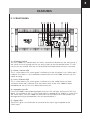
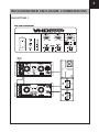
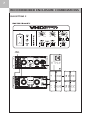
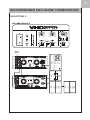
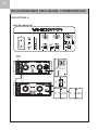
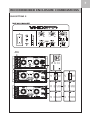
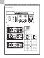
3
FEATURES
3.1 FRONT PANEL
- CONTINUED
6) Sub A & B Set Up
These switches are set according to which combination of subwoofers is being used with
the system - see Operation Modes.
7) System Single / Double
This switch sets the controller for use when either a single VHD 2.0 is being used or a
double system using 2 VHD 2.0’s are being used. In this mode another VHD 2000 would
be required to power the second VHD 2.0 and both switches should be set to ‘Double’.
8) Input Impedance
This rotary switch sets the Input Impedance of the VHD 2000 to match that of the mixer
or other device supplying the audio signal to the VHD 2000’s input. This is especially
important when driving longer cable runs and it enables the line to be driven correctly
without any losses or other interference. Ideally an LD4 line driver should be used. See
Using the System.
9) Tilt
This switch when depressed electronically ‘tilts’ the dispersion of the VHD 2.0 down
vertically by 10°. The Tilt switch should only be used when a single VHD 2.0 system is
being used.
10) Master Level
This is the master level control for the system and will affect both the VHD 2.0 and the
subwoofer outputs.
11) Sub A / B Level
These are the level controls for the Sub A and B outputs; they are ‘post’ the Master
Level control
12) Full Range Vocal
When this switch is activated it enables the VHD 2.0 to be used as a full range system
without the need for subwoofers, ideally suited to vocal reproduction and light music
applications. The VHD 2.0 will run full range with a 60Hz roll-off added to the system for
protection. Note in this mode the subwoofer outputs will be muted to prevent incorrect
use of the system.