1
CX-MB-ATX User's Manual
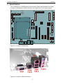
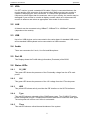
Specification
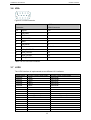
2.1 VGA
If a CRT monitor is used, a standard VGA cable (15 pins) is connected between the
monitor and the VGA connector of the carrier board. Make sure that your monitor is
capable of displaying the video resolutions. If a video mode generates horizontal
frequencies much higher than the maximum value of your monitor, the monitor may be
damaged! If your monitor is not able to display a mode, switch off or disconnect the
monitor in advance and select an appropriate video mode for the monitor.
2.2 LAN
A Network can be connected using 10BaseT, 100BaseTX or 1000BaseT standard
(depends on the module).
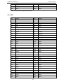
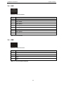
2.3 USB
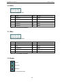
Up to four USB devices can be connected to the carrier board. A standard USB mouse
and a standard USB keyboard can be connected to a USB connector.
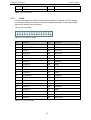
2.4 Audio
There are connectors for Line In, Line Out and Microphone.
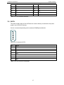
2.5 Port 80
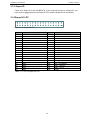
This Display shows the Port80 debug information (Postcode) of the BIOS.
2.6 Status LEDs
2.6.1
5V_SBY
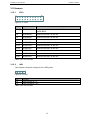
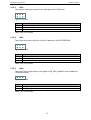
This green LED shows the presence of the 5V standby voltage from the ATX main
power.
2.6.2
12V
This green LED shows the presence of the 12V voltage from the ATX main power.
2.6.3
HDD
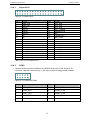
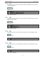
This yellow LED shows activity on either the IDE interface or the SATA interfaces.
2.6.4
Type
This red LED shows a mismatch of the COMExpress types. The CX-MB-ATX carrier
board is designed for type 2 COMExpress modules and can not used with other types.
The main power will not turn on if there is a mismatch.
2.6.5
Thrm
This red LED shows a critical thermal shutdown of the system.
9