1
4
UML-Based
Design
(with an emphasis on course project survival)
Distributed Embedded Systems
Philip Koopman
September 9, 2015
© Copyright 2000-2015, Philip Koopman
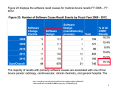
http://www.fda.gov/downloads/AboutFDA/CentersOffices/OfficeofMedicalP
roductsandTobacco/CDRH/CDRHTransparency/UCM388442.pdf
2
Where Are We Now?
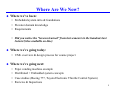
Where we’ve been:
• Embedded system intro & foundations
• Elevator domain knowledge
• Requirements
• Did you notice the “lessons learned” from last semester in the handouts last
lecture?(also available on-line)
Where we’re going today:
• UML overview & design process for course project
Where we’re going next:
•
•
•
•
Pepsi vending machine example
Distributed + Embedded system concepts
Case studies (Boeing 777, Toyota Electronic Throttle Control System)
Reviews & Inspections
3
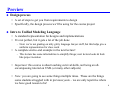
Preview
Design process
• A set of steps to get you from requirements to design
• Specifically, the design process we’ll be using for the course project
Intro to Unified Modeling Language
• A standard representation for designs and implementations
• It’s not perfect, but it gets a lot of the job done
– Note: we’re not grading on nitty gritty language lawyer stuff, but this helps give a
uniform representation for class work
• A complete end-to-end example in the next lecture!
– This lecture has some informalities to simplify things; next lecture looks & feels
like project notation
• Important: this course is about teaching survival skills, not being an allencompassing tutorial on UML (or many other subjects)
• Note: you are going to see some things multiple times. These are the things
some students struggled with in previous years – we are only repetitive where
we have good reason to be!
4
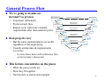
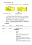
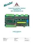
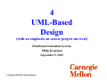
General Process Flow
We’re going to assume an
iterated Vee process
REQUIREMENTS
SPECIFICATION
• Top-down refinement
• Front-to-back flow
• Repeat cycle with more complex
requirements after mid-semester point
VALIDATION & TRACEABILITY
ACCEPTANCE
TEST
Review
Review
VERIFICATION &
TRACEABILITY
SYSTEM
SPECIFICATION
SYSTEM
INTEGRATION
& TEST
Review
Review
VERIFICATION &
TRACEABILITY
SUBSYSTEM/
COMPONENT
SPECIFICATION
Real projects vary
• But the same representations are useful
regardless of the sequencing
• Usually architecture & requirements
co-evolve
SUBSYSTEM/
COMPONENT
TEST
Review
Review
VERIFICATION &
TRACEABILITY
PROGRAM
SPECIFICATION
PROGRAM
TEST
Review
MODULE
SPECIFICATION
Review
VERIFICATION &
TRACEABILITY
UNIT TEST
Review
Review
SOURCE
CODE
Review
– (Lecture flows better with architecture first,
so that is today’s discussion)
This lecture concentrates on the pieces
• What the pieces really are
• How they fit together
• Next lecture is end-to-end example
5
Why UML (Or Any Other Notation?)
UML = “Unified Modeling Language”
• It isn’t actually Unified; it’s all the best known ideas tossed into the same sack
• And, it’s more a set of graphical techniques than a textual language
UML isn’t novel; it’s just a common representation
• Gives a way to exchange ideas via standardized set of diagrams
• Gives a standard way to document thoughts for later access
• UML is NOT a design methodology …
…there are many ways to use UML in a methodology and we’re just now
figuring out the better ways to do this.
There is not (yet) any “best” process
• “Best” varies depending on size of team, complexity/novelty, and company
culture
• But, it’s better to have some process than no process
• And, the ability to follow an arbitrary, but specified, process is important
6
UML-Based Process-“Lite” For Our Course
System-level requirements
• Use cases
• High level text requirements
Architecture – emphasis on “nouns”
• Class Diagrams & object descriptions – sensors, actuators, controllers
• Interfaces – network message dictionary
Software Requirements – emphasis on “verbs”
• Text-Based Scenarios – different scenarios for each use case
• Sequence Diagrams – graphical scenarios with emphasis on interaction “messages”
Design
•
•
•
•
Textual software requirements specification – per-module behaviors
State Charts – state transitions
Test Design
Failure analysis (covered later in semester)
Verification & Validation
•
•
•
•
Traceability
Unit testing
Integration testing
Acceptance testing
7
Why Not Just Write The Code?
That can work for up to perhaps 100 lines of code
•
•
•
•
Most embedded systems are a lot bigger
Most embedded systems have to be nearly perfect and on time
Problems tend to become exponentially worse with complexity/program size
Chapter 2 in text talks about this
The stakes are too high to get it wrong!
• But, there are countless projects that do get it wrong
– With resultant loss of money, jobs, lives, ….
Example:
In July 1999, General Motors had to recall 3.5 million vehicles because of
an anti-lock braking software defect. Stopping distances were extended by
15- 20 meters. Federal investigators received reports of 2,111 crashes and
293 injuries.
• http://autopedia.com/html/Recall_GM072199.html
• Other care companies have recalls too – GM is just an example
– Since then, GM has been working on software quality (and so have the others)
8
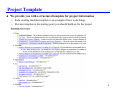
Project Template
We provide you with a structured template for project information
• Soda vending machine template is an example of how to do things
• Elevator template is the starting point you should build on for the project
9
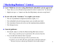
“Marketing/Business” Context
Goal: “Build an elevator using distributed embedded system approach”
• Note: there is a lot of historical precedent for what it means to be “an elevator”
• High level spec. is: “make it act like the HH primary elevator except better”
In our role as the “customer,” we require you to use:
•
•
•
•
Our set of predefined components (buttons, lights, etc.)
Our embedded network message types (you can add some later)
Our simulation framework in Java as the implementation platform
Our design process
General guidance:
• If in doubt, make it act like the Hamerschlag Hall main elevator
– But as long as satisfies project requirements, OK to deviate from this
• You can add extra features later in project
– You can add network messages with our permission only
– In general, you can NOT add extra system objects until after mid-term…
… because everyone in the past got themselves into trouble doing it!
10
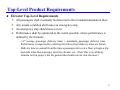
Top-Level Product Requirements
Elevator Top-Level Requirements
1.
2.
3.
4.
All passengers shall eventually be delivered to their intended destination floor.
Any unsafe condition shall cause an emergency stop.
An emergency stop should never occur.
Performance shall be optimized to the extent possible, where performance is
defined by the formula:
–
( 4 * average_passenger_delivery_time) + maximum_passenger_delivery_time
Performance is improved by reducing that value (short delivery times are better).
– Delivery time is counted from the time a passenger arrives at a floor to begin a trip
and ends when that passenger exits the elevator car. (Note: this is an arbitrary
formula for this project, but the general idea holds true for real elevators.)
11
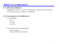
What’s an Architecture?
Architecture definitions:
• System: The structure – in terms of components, connections, and constraints –
of a product, process, or element. [Rechtin96]
For our purposes, an architecture is:
• A set of objects
– Sensors
– Actuators
– Controllers
• The interfaces between those objects
– Network messages
– Analog interface pseudo-messages
12
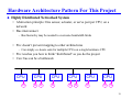
Hardware Architecture Pattern For This Project
Highly Distributed Networked System
• Abstraction principle: One sensor, actuator, or servo pair per CPU, on a
network
• Bus interconnect
– Bus hierarchy may be needed to overcome bandwidth limits
• Pro: doesn’t prevent mapping to other architectures
– Can simply co-locate code for multiple CPUs on a single hardware CPU
• Pro: teaches you how to think “distributed” as you do the project
• Con: bus can be a bottleneck
CPU
CPU
CPU
CPU
CPU
CPU
A
S A
S
S A
S
S A
13
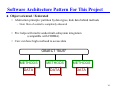
Software Architecture Pattern For This Project
Object oriented / Federated
• Abstraction principle: partition by data types, hide data behind methods
– Note: flow of control is completely obscured
• Pro: helps with multi-vendor/mult-subsystem integration
(compatible with CORBA)
• Con: can have high overhead to access data
OBJECT "BUS"
METHODS
METHODS
METHODS
DATA
DATA
DATA
14
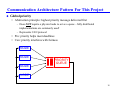
Communication Architecture Pattern For This Project
Global priority
• Abstraction principle: highest priority message delivered first
– Does NOT require a physical node to act as a queue – fully distributed
implementations are commonly used!
– Represents CAN protocol
• Pro: priority helps meet deadlines
• Con: priority interferes with fairness
NODE
NODE
NODE
PRIORITY
QUEUE
NODE
15
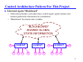
Control Architecture Pattern For This Project
Federated Agents/“Blackboard”
• Abstraction principle: each object has a control agent; agents monitor and
transmit global state information for coordination
• “Blackboard” has shared state variables
"BLACKBOARD"
SHARED GLOBAL
STATE INFORMATION
A
AGENT
A
S A
AGENT
S
S A S
A
AGENT
A
S
S A
16
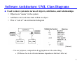
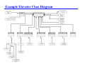
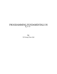
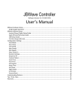
Software Architecture: UML Class Diagrams
Used to show system in terms of objects, attributes, and relationships
• Objects are “nouns” in the system
• Attributes are local state data within an object
• This is “sort of” an architectural diagram
[Rational]
– For our purposes, composition & aggregation are the same thing
» (Difference has to do with class/instance dependencies that don’t affect us)
17
Example Elevator Class Diagram
18
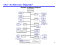
Our “Architecture Diagram”
19
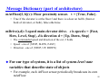
Message Dictionary (part of architecture)
mAtFloor[f, b](v): Floor proximity sensor. v = {True, False}.
• True if the elevator is at the floor f and there is a door on hall h (front or
back of elevator, or both), false otherwise.
mDrive(s,d): 3-speed main elevator drive. s is speed s = {Fast,
Slow, Level, Stop}, d is direction d = {Up, Down, Stop}
• The commanded speed and direction of the car; 2 fields
• Speed - one of {STOP, SLOW, FAST}
• Direction - one of {STOP, UP, DOWN}
For
our type of system, it is a list of system-level state
variables that describe state of objects
• For example, each AtFloor sensor periodically broadcasts its own
mAtFloor
20
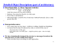
Detailed Object Descriptions (part of architecture)
DoorOpened[b, r]: Door Opened switches
• One per Door [b, r] for b = {Front, Back}
and r = {Left, Right}.
(total four sensors for two pairs of doors)
• Indicates True when the Door[b, r] is fully open.
• Set to False at initialization.
• mDoorOpened[b, r] shall be True if and only if mDoorPosition[b, r] has a value
greater than 490.
…
Interpretation notes:
• [b,r] means there are four doors: LeftFront; LeftRear; RightFront; RightRear
• (v) means that the object broadcasts the value (v) which in this case is:
– True means door is fully open
– False means door is not fully open (might be partway open – does not imply
closed)
We have intentionally designed the elevator so messages broadcast the
internal state of each architectural object
• There are other ways to do things in other approaches.
21
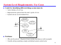
System-Level Requirements: Use Cases
Useful for identifying different things system must do
• Actor initiates a Use Case
• Represents the system from the actor’s point of view
• System can act on environment too
REQUEST
ELEVATOR
ENTER
ELEVATOR
PASSENGER
EXIT
ELEVATOR
OPEN
DOORS
DOOR CONTROLLER
CLOSE
DOORS
Problems:
• Who are the actors? (In general must include machines as well as people)
• Usually end up assuming a single centralized system control actor
22
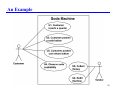
An Example
23
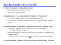
How Big Should A Use Case Be?
There is some art to sizing the use cases
• End-to-end ride on elevator is too big
• One line of code is too small
In general, use cases are intended to capture a “transaction”
• E.g., request a bank balance on an automated teller machine
• Usually, a user session has multiple transactions (request balance; withdraw
money; …)
In elevator case, it should be a situation that is a nice building block
• For example, approach elevator and tell it you want to go up/down
– Or, “make a hall call” for short
• Names should be 2-5 words long and relatively descriptive, with emphasis on
VERBS / actions
– These are about how users want to use the system, not how the system is built
Let’s talk about scenarios so you can see how size affects the next step
24
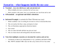
Scenarios – what happens inside the use case
Nominal – ways in which user and system interact
•
•
Often multiple alternate scenarios for each use case
Each scenario is the same “size” as a particular use case from end to end
Off-nominal – exceptional and failure situations
Informal Example (a scenario for Enter Elevator use case):
•
1.
2.
3.
4.
5.
Initial condition: user is waiting for elevator to arrive in desired direction
The car reaches the floor, stops, and opens its door
The car illuminates appropriate direction lantern
User enters
The car clears the hall call that was just serviced
The car closes doors and extinguishes direction lantern
Note that multiple scenarios are invoked for end-to-end service
•
•
Commonly scenarios are independent in “toy” problems and bank ATMs
But, NOTE: standard UML does not have any notion of Use Case order
25
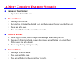
A More Complete Example Scenario
Summary Description:
•
Pre-conditions:
•
•
•
•
Open doors from within car
Passenger is in the car.
Elevator has arrived at the desired floor, but the passenger has not yet exited the car.
Doors are fully open.
The car call button for the current floor is not lit.
Scenario actions:
1. Doors begin to close, which will prevent passenger from exiting the car.
2. Passenger’s brain turns back on and (s)he presses car call button for current floor
before doors are fully closed.
3. Doors stop closing and reopens fully.
Post-conditions:
•
•
•
Passenger is still in the car.
The doors are fully open.
The car call button for the current floor is not lit.
26
How Big Is A Use Case? – Revisited
Using an elevator is a series of use cases
• Example: hall call, elevator moves to start floor, doors open, enter elevator, car
call, doors close, elevator moves to destination floor, doors open, exit elevator,
doors close
Each use case has multiple scenarios – almost always more than 1!
• Scenarios within use case must have compatible pre- & post-conditions
• Post-conditions of one scenario need to match pre-conditions of next scenario
Thus, use cases should be sized to manage complexity
• Big enough use case to have a handful of reasonable scenarios
• Split at natural breaking points to minimize # of pre- & post-conditions
Related question – how detailed is a scenario?
• Stay tuned for answer … but first we have to talk about Sequence Diagrams
27
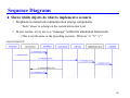
Sequence Diagrams
Shows which objects do what to implement a scenario
• Emphasizes interaction/communication among components
– “Feels” closer to a design at the system/interaction level
• In our course, every arc is a “message” within the simulation framework
– (This is not the same as the preceding scenario. What are “a” “b” “c”?
28
[Rational]
29
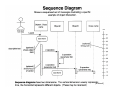
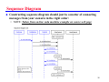
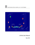
Sequence Diagram
Constructing sequence diagram should just be a matter of connecting
messages from your scenario in the right order:
• NOTE: Taken from on-line soda machine example on course web page
30
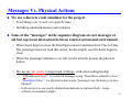
Messages Vs. Physical Actions
We use a discrete event simulator for the project
• Everything is an “event” at a specific time
• Including simulated sensors and actuators
Some of the “messages” in the sequence diagram are not messages at
all, but represent interaction between control system and environment
• When doors begin to close the DoorOpen sensor transitions from True to False.
The passenger does not read this sensor, he/she simply sees the doors begin to
close
• When the passenger indicates a car call, he/she actually presses the physical
button
• We use an “m” prefix to keep track of things, with color-coding backup
– “mDoorMotor(Close)” is a network message saying “DoorMotor ordered to close”
– “DoorOpen(False)” is a physical action saying “passenger saw the door go to nonOpened”
– In the project we use nearly identical mechanisms to represent both – keeps
software environment simple
31
How Detailed Is A Scenario?
You can have a scenario that is a text version of the SD
Here is a very detailed scenario for the preceding SD:
1. Door controller commands doors to close. (mDoorMotor(Close) message)
2. Doors begin to close. (DoorOpen sensor becomes False)
3. Passenger presses car call button for current floor before doors are fully closed.
(CarCall[f,h] button Pressed)
4. Car call button sends sensor CarCall message to car call button controller.
(mCarCall[f,h](Pressed) message)
5. Car call button controller sends CarCall message to door controller.
(mCarCall[f,h](Pressed) message)
6. Door controller commands doors to open. (mDoorMotor(Open) message)
7. Doors become fully open, triggering mDoorOpen(True) message.
8. Passenger observes door fully open (DoorOpen(True))
9. Door controller commands doors to stop. (mDoorMotor(Stop) message)
32
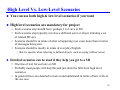
High Level Vs. Low-Level Scenarios
You can use both high & low level scenarios if you want
High level scenarios are mandatory for project
• Each scenario step should have, perhaps 1 to 3 arcs in SD
• Each scenario step typically involves a different actor or object initiating a set
of related SD arcs
• Scenario should be in terms of what is happening (use case) more than in terms
of messages being sent
• Scenario should be mostly in terms of everyday English
– But, be specific when referring to defined objects, such as saying AtFloor sensor
Detailed scenarios can be used if they help you get to a SD
• One line of text for each arc on SD
• Probably most people will skip this and just draw the SDs from high level
scenarios
• In general this is too detailed to look at and understand in terms of how it fits to
the use case
33
Use Cases; Scenarios; SDs revisited
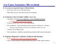
Use cases are general types of interactions
• Set of use cases covers all interactions
• More than one use case often invoked in sequence
Scenario is a list of actions within a Use Case
• Generally each Use Case completely “owns” multiple Scenarios
– Each Use Case has one or more scenarios
• Scenario is one way a Use Case is performed
• Pre-conditions: which situations must be true for scenario to “execute”
– Scenarios need mutually exclusive pre-conditions within a use case
• Actions: list of things to do
• Post-conditions: conditions summarizing situation after actions take place
Sequence Diagram is a picture of objects and messages
• Each Scenario has exactly one Sequence Diagram
• This is a more rigorous notation that shows how to make objects behave
34
Textual Software Behaviors
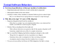
Text-based specification, written per module of architecture
• English/psuedocode behaviors of each architectural component
• Discussed in detail in the next lecture
• Usually in terms of how module or actuator behaves given a sensor input
– But, we can abstract this as saying behavior in response to input messages
Why this extra step? It’s not a UML diagram
• Sequence diagrams look from the outside in
– Often there is a simpler way to do implementation than a case statement that
handles each different scenario/sequence diagram
• Think of this as looking from the inside out
– What software behaviors are required so that all the sequence diagrams work?
– Sometimes simple behaviors suffice for complex interactions
• But we need this bridging step before jumping to design to also catch:
– Things that it is supposed to not do or guarantee never happen
– Situations where order is unimportant or there are timing constraints
– Assumptions made in design that other modules have to respect
• Yes you can use ad hoc text boxes in UML diagrams, but that’s a mess
35
Example Elevator Behavioral Requirements – 1
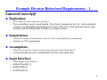
LanternControl[d]
Replication:
•
(How many are there and where are they?)
• Two controllers, one for each lantern {Up, Down} mounted in the Car. Each controller
controls two lightbulbs in parallel (one by each of the Car's front and back doors), and
actuates each front/back pair of bulbs as a single actuator.
Instantiation:
•
•
(What are settings at initialization; when are they created (default is permanent))
Lanterns are Off at initialization.
Assumptions:
•
(What do you need to assume to meet constraints given listed behaviors?)
• CarLanterns[d] are never commanded to be On at the same time.
Input Interface:
•
(What inputs are available?)
• mDoorClosed[b, r]
• mDesiredFloor
• mAtFloor[f, b]
36
Example Elevator Behavioral Requirements – 2
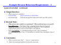
LanternControl[d] (continued)
Output Interface:
• (What outputs are available?)
• CarLantern[d]
(physical interface to light bulbs!)
• mCarLantern[d]
(network message that sends state to the rest of the system)
Internal State:
• (What private state variables are maintained? What notational macros are used?)
• DesiredDirection = {Up, Down, Stop} computed desired direction based on
comparing CurrentFloor with Floor desired by Dispatcher. This is implicitly
computed and used as a macro in the behavior descriptions.
• Note: CurrentFloor, is a shorthand notation for the value of whichever
AtFloor[f,Stop] is True, if any. If CurrentFloor is invalid it has a mnemonic value of
None.
Constraints:
• (What invariants must hold? – “passive” requirements.)
7.1 Both CarLanterns[d] shall not be On at the same time.
37
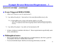
Example Elevator Behavioral Requirements – 3
LanternControl[d] (continued)
Event-Triggered BEHAVIORS:
• (What active behaviors must be implemented?)
7.2 Any mDoorClosed[j, k] = false shall set CarLantern[DesiredDirection] to On.
7.2.1 If DesiredDirection is Stop, both lanterns shall be set to Off.
» (Note: this is a more convenient way to write two parallel cases for DesiredDirection Stop and not
Stop for 7.2. It implicitly assumes that the triggering condition of mDoorClosed[j,k] being False has
been met)
7.3 Any mDoorClosed[j,k] = true shall set CarLantern[d] to Off.
• Is there a behavior problem with above? These requirements superficially seem
to be contradictory.
Philosophical notes:
• These requirements are really half-way to implementation (but that’s good for
our purposes because it makes them concrete)
• You need detailed object interfaces & message dictionary to do this
38
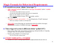
Magic Formula for Behavioral Requirements
Event-driven system (think “interrupts”):
• (#ID) <message received> shall result in <messages transmitted> and/or <variable
values assigned>
–
–
–
–
Account for all possible messages received
Account for all possible messages that need to be transmitted
Make sure all variables are set as required
OK to transmit multiple messages; OK to set multiple variables
• OK to also use:
<message_received> and variable == X on left hand side of “shall” statement
– OK to use multiple variables on left hand side
• ONLY ONE received message per requirement (network serializes messages;
simultaneous reception of multiple messages is impossible)
Time-triggered system is different (think “polled I/O”):
• Keep copies of last value received for each message and periodically set outgoing
message values for next periodic transmission
• Permits using multiple received messages
– We’ll see this later in more detail.
EVERY VERB GETS A NUMBER
• Numbers are used to tracing requirements to implementation & tests later on
39
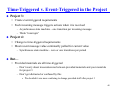
Time-Triggered v. Event-Triggered in the Project
Project 3:
• Create event-triggered requirements
• Each incoming message triggers actions when it is received
– Asynchronous state machine – one transition per incoming message
– Think “interrupts”
Project 4:
• Change to time-triggered requirements
• Most recent message value continually polled for current value
– Synchronous state machine – zero or one transitions per period
But…
• Provided materials are all time-triggered
– Don’t worry about inconsistencies between provided materials and your materials
for project 3
– Don’t get distracted or confused by this
» We decided it was more confusing to change provided stuff after project 3
40
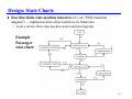
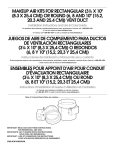
Design: State Charts
Describes finite state machine behaviors (it’s an “FSM transition
diagram”) – emphasizes how object achieves its behaviors
• Look a lot like finite state machine state transition diagrams
Example
Passenger
state chart:
41
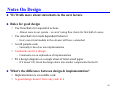
Notes On Design
We’ll talk more about statecharts in the next lecture
Rules for good design
• Use flowcharts for sequential actions
– Almost none in our system – we aren’t using flow charts for first half of course
• Use statecharts for mode dependent behavior
– Every non-trivial module in the elevator will have a statechart
• Avoid pseudo-code
– Generally it devolves into implementation
• Comments aren’t a design
– Comments are an explanation of implementation
• Fit a design diagram on a single sheet of letter-sized paper
– If it doesn’t fit, break the design down into smaller components that do fit
What’s the difference between design & implementation?
• Implementation is executable code
• A good design doesn’t have any code in it
42
Implementation: Java Code
Elevator implemented in Java with a course-supplied simulation
framework
• We give you the software to implement the environmental objects (e.g., people)
• We give you some example code based on last year’s project
– It is simpler, but it gives you a starting point
• You create Java code to implement the Statecharts and any algorithms required
43
Testing: Checking It Actually Works
Some possible types of testing:
• Exercise all arcs of statecharts (one way to do unit test)
• Exercise each sequence diagram (one way to do integration test)
• Exercise concurrent use cases with passengers (one way to do acceptance test)
– But, need to address things like performance as well for acceptance testing
Short description of the “environment” of the test, includes:
•
•
•
•
•
•
•
What level (unit, subsystem, simulation)
What units included
What resources needed (simulation, input files, etc.)
What setup is to be done for the test
The test itself (description of inputs/actions in actual test)
Expected results
Requirements verified
Can more or less use this approach at each level of abstraction, but no
rigorous process available to do that
44
Three Types of Testing We’ll Use
Unit Test
• Send messages at one object alone in simulation framework
• See if response messages match expectations based on Statecharts
Integration Test
• Set initial conditions & send messages to whole elevator
• See if responses match expectations based on Sequence Diagrams
Acceptance Test
• Run elevator with passenger workload
• See if responses match Use Cases & end-to-end passenger delivery
Quick Check: What is the (indirect) relationship between Integration
Tests and Use Cases?
• { More than one | At least one | Exactly one } integration test per use case
45
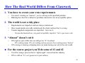
How The Real World Differs From Classwork
1. You have to create your own requirements
•
•
You aren’t creating an “answer”, you’re solving an ill specified problem.
Blaming the client for a defective problem statement is not an acceptable option.
2. The world is not a tidy place
•
•
•
Requirements are imperfect and not always understood.
Once requirements are really understood, the client realizes they’re wrong.
Vendor-supplied components are imperfect. Get over it.
–
Our provided materials are very good, but probably imperfect. You’ve got source code.
3. “Almost” doesn’t cut it
•
90% right or just a little late can still get an “A” in school
–
•
90% working means 10% not working, and any percent of not working means “broken”
10% wrong or missing a shipping date can mean losing your job in the real world
For the course project you’ll do some of #1 and #2
•
•
You’ll be using a process that is “lightweight”, but not bad for industry
90% is still an “A” (so I guess we’re just softies)
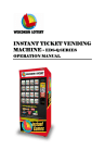
46
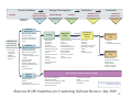
Product Definition
Outputs:
Production
Detailed Design
Software
Confidence In
Implementation
Sustained
Performance
Review #1
Review #2a
Review #2b
Review #3
Review #4
Software
Architecture
- Product goals:
- Functionality
- Performance
- Reliability
- Migration plan
- Schedule
Verification
Project Plans &
High Level Design
Suggested
Reviews:
Marketing &
Engineering
Specification
Design & Development
PDR*
- Subsystem/object definitions
- Interface definitions
- Architectural descriptions for
HW, SW, communications,
control, ...
Software
Requirements
SRR*
- Functional requirements
- Nonfunctional requirements
- Software process plan
complexity, staffing, schedule,
budget
- V&V and test plans
- Deployment plan
- Maintenance/upgrade plan
- Human interface requirements
- Risk issues
- Traceability matrices
Supplier
Strategy
- Operating system
- Libraries
- Development tools
- Communication network protocol
Design
CDR*
- Module/object
descriptions
- Dependency
descriptions
- Interface descriptions
- Detailed design of each
unit (UML is a best
practice)
- Performance/resource
budgets
- Failure mode/safety
analysis
- Traceability matrices
- Risk areas
Implementation
SVVPR*
Software
Inspections
- Code/Documentation
- Design
- User Manual
- Coding Standards
- Documentation Standards
- User Interface Standards
- Reuse Standards
- Unit test results
- Internal code inspection
results
- Traceability matrices
Verification,
Validation
& Test
Deployment
Plan
IV&V*
- Field trials
- Production
- Configuration Management
- V&V audits
- Test plans
- Test results
- Test against configurations
- Performance, usability,
stability
- Safety
- Traceability matrices
SCMPR*
Maintenance
Plan
- Problem reporting
- Configuration management
- Defect tracking
- Upgrade releases
- Traceability of defects/
features to upgrades
Development Process Guidance (E-CAM)
- Requirements Management
- Software Project Plan
- Software Troubleshooting & Oversight
- SW Subcontract Management
- SW Quality Assurance
- Configuration Management
- Testing
- Inter-group coordination
- Peer Review
* = Major Review Stages as defined
in IEEE Std. 730-1998
Emerson SCOE Guidelines for Conducting Software Reviews, July 2001
47
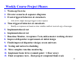
Weekly Course Project Phases
1. Warm-up Exercise
2. Elevator scenarios & sequence diagrams
3. Event-triggered behaviors & statecharts
•
Arrival of a single message triggers some response
4. Time triggered behaviors & statecharts
•
Modify so responses are based on state variables and last received copy of messages
5. Implementation & test
6. Implementation & test
7. Run-time Monitor, Acceptance Tests, mid-semester working elevator
8. Improved dispatcher requirements & initial design
9. Finish improved dispatcher design; create unit tests
10. Testing and network scheduling
11. More complete run-time monitoring
12. Implement faster drive (commit point > 1 floor away)
13. Final acceptance tests – final project completed finals week
48
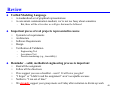
Review
Unified Modeling Language
•
•
A standardized set of graphical representations
A convenient communication medium; we’re not too fussy about semantics
–
Important pieces of real projects represented in course
•
•
•
•
•
System-level requirements
Architecture
Software Requirements
Design
Verification & Validation
–
–
–
But, there will be a few rules we will give that must be followed
Engineering Test
Acceptance Test
Process monitoring (e.g., traceability)
Reminder – solid, methodical engineering process is important
•
•
•
•
•
•
Read all the assignment
Follow all the directions
If we suggest you use a checklist – use it! It will save you grief
“I forgot” or “I didn’t read the assignment” aren’t acceptable excuses
Neither is “I ran out of time”
We strongly suggest your group meets on Friday after recitation to divide up work
49