1
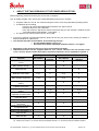
POWEO® hoists/patient lifters
S17 99 102 EN “Full version”
Service Tool
software
TECHNICAL MANUAL
This document is available under reference S17 99 103EN through our technical and
commercial services. It is referenced DOTE044EN in our documentary database.
This document is the property of SCALEO Medical. Any reproduction or distribution is
prohibited without written permission.
Ref. DOTE044EN- S1799103 v1_01-2013 POWEO Service Tool Full version technical manual
Page 1 / 36
1
ABOUT THE TWO VERSIONS OF THE POWEO SERVICE TOOL
Before beginning, please insure that your service tool is complete.
S17 99 100EN English “Full” version of the SCALEO Medical service tool includes:
A specific cable ref: S17 99 101 used for linking the hoist to a PC using Windows operating system
A USB flash drive including:
• The S17 99 102 EN SCALEO Medical software “full” option version.
• Windows drivers for the USB cable
• The user manual in pdf format. Please insure also that your PC includes a software for pdf
format files (like Acrobat Reader , Foxit reader … )
The present user manual referenced S17 99 103 EN
If you note a missing or deteriorated element, please do not use your service tool: contact your dealer or
SCALEO Medical for replacement.
This manual describes functionalities of the following versions :
• S17 99 102EN software revision 1.0
• S16 30 001 main board embedded software revision 1.3 or higher
Depending on the variant of the service tool, functionalities will differ.
Qualified technicians will be equipped with the “full” version. However, the user manual of the
« full » version, which includes description of advanced features, can be supplied on request. e
Function
Light version
Embedded
PC sotfware
interface
Full version
Embedded
PC sotfware
interface
Test of the main electronic
board
X
Main actuator change
X
Main fuse test
X
X
Real time clock repair
X (1)
X
X (1)
X
Main actuator monitoring
X (1)
X
X (1)
X
X
X
X
X
Weight measurement
setting
Setting the maximum
capacity of the hoist
Periodical inspection period
setting
Setting the date of periodical
inspection at current date
Disable the periodical
inspection alarm
Real time setting of the hoist
Driving of the hoist without
the remote
Reading all the parameters
of a POWEO hoist
Data saving
Writing hoist parameters in a
ASCII text file
Writing hoist history in a
ASCII text file
X
X (2)
X
X (2)
X
X
X
X
X
X
X
X
X
X
X
X
X
X
X
X
X
X
X
X
X
(1) Performed by reading hoist parameters
(2) Limited to 6 months or 12 months with the embedded interface. 1 to 98 months with the software interface
Ref. DOTE044EN- S1799103 v1_01-2013 POWEO Service Tool Full version technical manual
Page 2 / 36
2
CONTENT
1
2
3
ABOUT THE TWO VERSIONS OF THE POWEO SERVICE TOOL ......................................................... 2
CONTENT................................................................................................................................................... 3
OBJECT, EQUIPMENT REQUIRED .......................................................................................................... 5
3.1
Object.................................................................................................................................................. 5
3.2
Contents of the manual :..................................................................................................................... 5
3.3
Equipement required: ......................................................................................................................... 5
4 DEFINITIONS AND PICTOGRAMS USED ................................................................................................ 6
5 GENERAL INFORMATION ........................................................................................................................ 7
5.1
Example of a SCALEO Medical hoist : POWEO 150 model .............................................................. 7
5.2
S1630001 Main electronic board main components : ....................................................................... 8
5.3
S1630001 main board main functions ................................................................................................ 9
5.3.1 Driving the hoist ............................................................................................................................. 9
5.3.2 Storage capabilities ....................................................................................................................... 9
5.3.3 Hoist parameters ........................................................................................................................... 9
5.4
Removable and soldered memory circuits ......................................................................................... 9
6 AVAILABLE HUMAN TO MACHINE INTERFACES................................................................................. 10
6.1
Remote indicators : ........................................................................................................................... 10
6.2
Main board indicators and micro switches :...................................................................................... 11
6.3
PC software ...................................................................................................................................... 12
6.3.1 Software installation : .................................................................................................................. 12
6.3.2 Software communication with the hoist : ..................................................................................... 12
6.3.3 Using the software : ..................................................................................................................... 13
6.3.4 Closing the sotfware .................................................................................................................... 14
6.3.5 In case of a dysfunction : ............................................................................................................. 14
7 HOW TO USE THIS USER MANUAL: ..................................................................................................... 15
8 CHANGING THE PERIODIC INSPECTION TIME PERIOD : .................................................................. 16
8.1
How the « Periodic inspection » alarm works ? ................................................................................ 16
8.2
How to change the time period : ....................................................................................................... 16
8.2.1 With the hardware HMI : .............................................................................................................. 16
8.2.2 With the PC sotfware : ................................................................................................................. 16
8.3
Suppression of the periodic inspection alarm ................................................................................... 17
8.3.1 With the hardware HMI : .............................................................................................................. 17
8.3.2 With the PC sotfware : ................................................................................................................. 17
9 USING REMOTE CONTROLLER ALARMS : .......................................................................................... 18
9.1
Alarm identification: .......................................................................................................................... 18
9.1.1 With the hardware HMI : .............................................................................................................. 18
9.1.2 With the PC sotfware : ................................................................................................................. 18
9.2
Solving the « main fuse » defect : .................................................................................................... 19
9.3
Solving the « RTC » problem : ......................................................................................................... 20
9.3.1 With the hardware HMI : .............................................................................................................. 20
9.3.1 With the PC sotfware : ................................................................................................................. 20
9.4
Solving the « main actuator used over 97%» problem : ................................................................. 21
9.4.1 With the hardware HMI : .............................................................................................................. 21
9.4.1 With the PC sotfware : ................................................................................................................. 21
10
PERIODIC INSPECTION : ............................................................................................................... 22
10.1.1
With the hardware HMI : ......................................................................................................... 22
10.1.1
With the PC sotfware : ............................................................................................................ 22
11
CHANGING THE MAIN ACTUATOR ............................................................................................... 23
11.1 Calibration of the weight measurement with a new actuator : .......................................................... 23
11.1.1
With the hardware HMI : ......................................................................................................... 23
11.1.2
With the PC sotfware : ............................................................................................................ 24
11.2 Resetting the usage value of the main actuator : ............................................................................. 25
11.2.1
With the hardware HMI : ......................................................................................................... 25
11.2.2
With the PC sotfware : ............................................................................................................ 25
Ref. DOTE044EN- S1799103 v1_01-2013 POWEO Service Tool Full version technical manual
Page 3 / 36
12
12.1
12.2
12.3
12.4
12.5
13
13.1
13.2
13.3
13.4
14
14.1
14.2
14.3
14.4
14.5
15
CONFIRMATION of a MAIN BOARD FAILURE : ............................................................................. 26
Insure that the main board is powered : ........................................................................................... 26
Check the remote controller ............................................................................................................. 26
Check the main board with the software service tool : ..................................................................... 26
Check the main board with the embedded HMI ............................................................................... 27
Check the electrical connexions : ..................................................................................................... 27
CHECKING THE MAIN BOARD FUNCTIONALITIES WITH THE SOFTWARE : ........................... 28
Reading all the parameters of the hoist ............................................................................................ 28
Test of the main board ...................................................................................................................... 29
Driving the hoist without a remote controller : .................................................................................. 29
Saving the hoist information ............................................................................................................. 30
MAIN ELECTRONIC BOARD REPLACEMENT : ............................................................................ 31
Removable memory integrated circuit : ............................................................................................ 31
Replacing the main circuit board ...................................................................................................... 32
Quick review of the parameters : .................................................................................................... 32
Testing the circuit board ................................................................................................................... 33
Driving the hoist without a remote controller : .................................................................................. 33
NOTES.............................................................................................................................................. 34
Ref. DOTE044EN- S1799103 v1_01-2013 POWEO Service Tool Full version technical manual
Page 4 / 36
3
OBJECT, EQUIPMENT REQUIRED
3.1
Object
The goal of the technical manual is to help qualified technicians to operate preventive and curative
maintenance operations on POWEO® hoists manufactured by SCALEO Medical.
Prerequisites for this operations are:
-
The technician must be skilled in electronics
The technician must have a minimum experience in using Windows based computers
The technician should have experience in maintenance of patient lifters
SCALEO Medical provides trainings for periodic inspection and maintenance of patient lifters.
Before any action, please read carefully the user manual provided with the device: user manuals include
many information relating the operations and trouble shooting.
The POWEO® hoists are medical devices that could break in case of an inappropriate
mechanical element, causing serious injury to the patient or staff.
Accordingly:
- The hoist should be maintained only by qualified personnel with original spare
parts.
- In case of accident on equipment maintained or modified by non-authorized
personal, SCALEO Medical cannot be held responsible.
- Any work performed by untrained personnel will void the warranty of the
equipment.
3.2
Contents of the manual :
This manual contains the information needed to work on the electronic components of the lifter in two types
of conditions:
3.3
With a PC computer and equipment (cable and software) to communicate with the main PCB. This
configuration is preferable.
In the absence of computer: the operations are performed via a man / machine interface using
LEDs and micro-switches soldered on the main circuit board.
Equipement required:
S16 30 002 POWEO remote controller (provided with the hoist)
Complete S17 99 110EN (English light version) service tool
A windows based computer with USB ports (USB 1, 2, 3 type)
Original spare parts, including fuses, electronic boards
Ref. DOTE044EN- S1799103 v1_01-2013 POWEO Service Tool Full version technical manual
Page 5 / 36
4
DEFINITIONS AND PICTOGRAMS USED
•
Actuator:
jack. Electrical component used for moving parts of the hoist.(opening the legs or
lifting the patient).
•
BP :
•
Chaser :
Flashing effect obtained with LEDs : LED1, LED2, LED3, LED2, LED1 alternatively
light on and off .
•
CP :
•
Cycle :
a « cycle » is defined as rising and lowering half of the SWL in a 50cm range, around
the average position of the arm. Such a “cycle” allows the electronics to manage battery use and
define the low threshold of the battery.
•
Driver :
•
HMI :
Human/Machine Interface : any hardware or software device used by a machine to
communicate with human beings. Exemples : Display device, buttons, switches…
•
Hoist:
Hoist or patient lifter : a medical device intended to lift or transfer disabled persons.
•
LED :
Light Emitting Diode
•
LP :
Hoist/ lifter
•
PCBA :
Printed Circuit Board Assembly: a support populated with electronic components.
Also named “electronic board” or “electronic card”.
•
RAZ :
Return to zero
•
RTC :
Internal clock (Real Time Clock)
•
SN :
Serial number
•
Transfer :
a transfer cycle is defines as beginning by moving the patient/charge, ends when the
lifter is not used for at least five minutes.
•
SW :
micro Switch
•
SWL :
Safe Working Load : maximum permissible load for the hoist, as defined by the EN
10535 standard.
push button
Periodic Inspection, as defined by the EN 10535 standard annex B
low level software used to manage (drive) external devices connected to a PC.
The following symbols are also used and report important information for the safety of people and
equipment:
This symbol is used to point out instructions and information related to work place
safety where injury may occur if the information is disregarded or ignored. Follow these
instructions and be careful and attentive at all times.
This symbol indicates important information regarding the use of the equipment. If not
taken into consideration, it may lead to damage or functional defects to the lifter or
other equipment.
This symbol indicates important and useful information. If taken into consideration, it will
help the operator of the lifter to work efficiently. It may help simplify routines and to
explain complicated facts.
=>
Indicates a remark or a tip/trick regarding the use of the hoist or the service tool
Ref. DOTE044EN- S1799103 v1_01-2013 POWEO Service Tool Full version technical manual
Page 6 / 36
5
GENERAL INFORMATION
5.1
Example of a SCALEO Medical hoist : POWEO 150 model
1. Chassis including : the main electronic board, 2
actuators for legs opening, electrical emergency
lowering device
2. Column
3. Arm
4. Rotating spreader bar
5. Electrical main actuator with mechanical
emergency lowering device
6. Removable battery with emergency stop button
7. 4 buttons remote
8. Manual emergency lowering device
9. Legs with electrical opening mechanism
10. Battery charger (not represented)
3. Arm
4. Suspension /
spreader bar
2. Column
7. Remote
6. Removable battery
with emergency
stop button
Manual emergency
lowering
5. Electric actuator
9. Legs
1. Chassis
Ref. DOTE044EN- S1799103 v1_01-2013 POWEO Service Tool Full version technical manual
Page 7 / 36
5.2
S1630001 Main electronic board main components :
The S1630001 electronic board has been designed for use within the whole range of POWEO® SCALEO
Medical mobile and ceiling hoists.
K8
K6
K2
U2
U6
K3
D6
D7
D8
F1
K4
S1
BP1
K1
K7
•
•
•
•
•
•
•
•
•
•
•
•
•
BP2
K8 : battery support for Real time clock (RTC)
NB : the battery must be Varta CR1220
K6 : connector for programming the board
U2 : removable integrated circuit (memory)
F1 : main fuse
K7 : remote and service tool connector
BP2 : emergency lowering button
D6 D7 D8 : LED1,2,3
S1 : SW1,2,3,4
BP1 : push button
K4 : battery connector :
o + : Brown
o - : Blue
K1 : main actuator connector
o + : Blue
o - : Brown
nd
K2 : 2 actuator connector (legs opening actuators)
o + : Brown
o - : Blue
K3 : 3rd actuator connector (active spreader bar)
o + : Blue
o - : Brown
Ref. DOTE044EN- S1799103 v1_01-2013 POWEO Service Tool Full version technical manual
Page 8 / 36
5.3
S1630001 main board main functions
5.3.1
•
•
•
•
•
•
3 actuators driving capability (one at a time)
Electrical emergency lowering
Main actuator software safety : the hoist stops if the load is over loaded (max value + 10kg)
Battery monitoring
Legs opening safety : the legs won’t be opened or closed if an obstacle is met
Alarms. The user will be warned by a visual alarm on the remote if
• Periodical inspection date is within two months
• Periodical inspection date has expired
• The main fuse it out of order
• The real time clock is out of order or not right
• The main actuator is 97% worn and must be changed
5.3.2
•
•
•
•
•
•
•
•
•
•
5.4
Storage capabilities
Date of first use : first power on of the hoist. This date is used to calculate the date of first periodical
inspection.
History of transfers per weight range: [10-30kg]] 30kg-60kg]] 60kg-110kg]] 110kg 170kg-]] CFS170kg].
History of actuators (main and legs opening) alarms
History of use of the emergency lowering device
History of the main actuator use
History of changes of the period of CP
History of changes of the value of CFS
History of main actuator replacements
History of battery recharges
Histroy of battery alarms
5.3.3
•
•
•
•
•
•
•
•
Driving the hoist
Hoist parameters
Hoist model
Maximum safety load of the hoist
Frequency of periodic inspection
Measurement of the battery voltage ( voltmeter function)
Consomption of the actuators
Weight measurement (ampere-meter function)
Setting the time of the RTC (year, day, hour)
Serial number of the hoist
Removable and soldered memory circuits
The electronic board includes two kinds of memory circuits : 3 integrated circuits (U3,4,5).are soldered on the
printed cicuit board, one (U2) is put on plastic support and can be removed .
The removable memory circuit must be removed from the PCBA and re used in the case of a
main electronic board replacement :
• Serial Number of the hoist
• Hoist model
• Weight measurement calibration data
• Date of commissionning
• Periodical Inspection period
• Main actuator wear level ( in %)
• Main actuator usage history
Ref. DOTE044EN- S1799103 v1_01-2013 POWEO Service Tool Full version technical manual
Page 9 / 36
6
AVAILABLE HUMAN TO MACHINE INTERFACES
6.1
Remote indicators :
Battery indicator
Service indicator
Up button
Down button
Legs opening button
Legs closing button
Indicators light up only when a button is pressed
The battery indicator displays the state of the battery every time a button is pressed
The service indicator is normally out, and lights up only when servicing is required.
In case of multiple date, they are displayed in sequence :
Example : Default + CP date expired => Orange – Blinking red – Orange – Blinking red
Please be aware of LED colors, and specially not to confuse red with orange. Continuous RED
state does not exist.
To make it short and simple:
- a blinking service indicator is always and only relating to periodical inspection, and NEVER
to a default.
- a continuous service indicator is always relative to a defect, NEVER to periodical inspection
Battery indicator
Service indicator
●
Continuous GREEN : capacity > 10 cycles
●
●
Continuous RED : capacity ≤ 10 cycles
BLINKING ORANGE : periodical inspection is to be
performed within 2 months
●
BLINKING RED : battery alarm. The hoist
cannot be operated except for a electrical
emergency lowering
CONTINUOUS ORANGE = default
●
●
BLINKING RED : periodical inspection date has been
passed
Ref. DOTE044EN- S1799103 v1_01-2013 POWEO Service Tool Full version technical manual
Page 10 / 36
6.2
Main board indicators and micro switches :
On the solder side of the main board can be found: 4 micro switches 3 LEDS, one push button.
In order to access to this interface the protection plate found under the chassis must be removed:
1
2
1
0
1 2 3 4
LEDs
3
Switches (SW)
Push Button
(BP)
Switches are ACTIVE / ON when put on the “1” position
Switches are INACTIVE / OFF when put on the “0” position
Example: on the picture above, the SW2 is the only active (ON) switch. SW1, SW3, SW4 are inactive (OFF)
Depending on the positions of the micro switches, the technician will be able to perform some operations or
to get information from the main board electronics.
At the start of the main board, the LEDs alternatively turn on and off.
This chase is intended to ensure that the card starts correctly, and that all LEDs are
operating.
How to use this interface (the hoist is of course battery powered)
•
•
•
•
Step 1 : Put the SW in the desired position
Step 2 : Press and keep the BP pressed
Step 3 : Depending on the SW « code » the LEDs go on and off and display a chase, depending on
the SW “code”
Step 4 : The LEDs all go on, then go off 3 times, last time being longer than the first two
Attention :
• If the LEDs act like described, the « code » has been taken in consideration, otherwise repeat the
operation since the first step.
• Do not release the push button until step 4 completion otherwise you will have to repeat the whole
operation
• The number of « chases » helps to be certain to have validated the right SW “code”
Only useful positions of the switches are described in this manual.
NEVER attempt to “try” other positions: some positions are used for changing parameters
of the hoist.
In the case of a bad “code”, the hoist could be totally out of service and require servicing
from SCALEO Medical.
Ref. DOTE044EN- S1799103 v1_01-2013 POWEO Service Tool Full version technical manual
Page 11 / 36
6.3
PC software
SCALEO Medical service tool software will only on Microsoft® Windows® based
computers. The service tool will NOT work on Mac Os, Linux, Android computers, smart
phones or tablets.
6.3.1
Software installation :
Copy/paste the English file « S17 99 102 Poweo Service Tool - Full EN- vx.x.exe » from the
USB memory stick to your desktop or any file. No installation is required.
Identify the version of the USB driver depending on your version of Microsoft Windows, and
perform the installation of the driver with the help of installation help files provided.
In the USB memory stick are also provided links to the cable manufacturer website, allowing you to
upload the last version of the driver. Most of the time, the installation process will only last a few seconds
from a single installation file.
6.3.2
Software communication with the hoist :
Pull the battery of the lifter out, and disconnect the remote from the lifter
Connect the S17 99 101 cable to the remote port, and then to a free USB port of the PC. Use
the marks on the connector for guide.
Guide
mark
If the driver has been correctly installed, the TTL to USB cable will be automatically recognized
by the computer.
Put the battery back on its support in order to power on the hoist.
Double click on the software icon « S17 99 102 Poweo Service Tool – Full EN - vx.x.exe » to
launch the service tool software.
Ref. DOTE044EN- S1799103 v1_01-2013 POWEO Service Tool Full version technical manual
Page 12 / 36
Follow indications on the screen
Once communication has been established between the hoist and the computer, the software
will indicate that the connection is done, and will display the hoist serial number.
Depending of previous USB devices installations on the computer, the software may have to try several
USB port before the connection to the hoist is established. Please wait until the connection is
established, or the computer to send an error message if no USB port is available.
6.3.3
Using the software :
Once connection established, hitting any key will display the main menu and main information
relative to the connected hoist.
To choose a menu, hit its number and then the ENTER key.
Main menu remains permanently displayed on the top of the software window.
Ref. DOTE044EN- S1799103 v1_01-2013 POWEO Service Tool Full version technical manual
Page 13 / 36
6.3.4
Closing the software
Choice in the main menu: Q
The software will display a message indicating that the hoist is disconnected.
Hitting any key when prompted to do so will close the software window.
6.3.5
•
In case of a dysfunction :
If the connexion fails :
o
o
o
o
o
Check the physical connection (cable) between the hoist and the PC.
Insure that the cable is correctly detected by the computer: disconnect it and then reconnect
it, the PC should detect the connection of a new peripheral and emit a specific sound.
Another software may use some COM ports, if the service tool indicates that there is no
COM port available, reboot your computer in order to free a port.
Reboot the hoist : press the emergency stop button (on the battery) WAIT 10 sec, and retry
again.
Check battery voltage, it should be around 25V DC. The service tool will not operate
properly if the battery voltage value is too low.
In case of a software "crash", the entire connection must be reset:
- Close the software by typing CTRL + C
- Disconnect the battery of the hoist and WAIT about ten seconds
- Reconnect the battery and restart the software
This operation will reset the software communication with the hoist, and the hoist
electronic card.
Ref. DOTE044EN- S1799103 v1_01-2013 POWEO Service Tool Full version technical manual
Page 14 / 36
7
HOW TO USE THIS USER MANUAL:
In order to assist you in your actions, the "operating mode" part of the manual is divided into sections to
meet identified needs.
Note: This guide refers only to defects associated with electrical / electronic parts of the POWEO hoists.
Actions in bold are described in this technical manual and require a service tool and / or specific training.
Other actions can be performed by a qualified technician.
Setting the « periodic inspection » alarms
For
Change periodic inspection time
period
Inhibit periodic inspection alarm
function
Use
PCB HMI or PC software
Do
Change periodic inspection time period
PCB HMI or PC software
Inhibit periodic inspection alarm
function
Managing hoist alarms (service indicator on the remote):
Alarm / defect
The hoist is not operating at all,
service indicator is continuous
orange
The hoist is operating well,
service indicator is continuous
orange
The hoist is operating well,
service indicator is continuous
orange
Possible cause
Main fuse of the main board is
broken
What to do ?
Confirm the defect with the PCB HMI
Change to fuse for a new one
RTC is defective
Confirm the defect with the PCB HMI or
with the software service tool
Fix the RTC problem
Confirm the defect with the PCB HMI or
with the software service tool
Change the main actuator for a new
one.
Main actuator is more than 97%
worn out.
Periodic inspection and preventive maintenance:
Alarm
The hoist is operating well,
service indicator is blinking
orange or red
The hoist is operating well,
service indicator is blinking
orange or red
Main actuator has been
changed
What to do ?
Perform a periodic inspection.
Reset periodic inspection alarm
How to use the service tool ?
Read hoist parameters
Perform a periodic inspection.
Reset periodic inspection alarm
Reset periodic inspection alarm once the
periodic
inspection
has
been
performed.
Reset main actuator use counter.
Perform a weight calibration with the
new actuator.
Use PCB HMI or PC software
Curative maintenance (defective hoist)
Alarm / defect
The hoist is not operating,
indicators on the remote do not
operate.
Possible cause
The remote is out of service /
the hoist is not powered
properly
What to do ?
Check hoist power supply
Check the remote controller
Chek connections
Use a HMI to check if the main board is
powered
Replace the main board
Test the main board
Ref. DOTE044EN- S1799103 v1_01-2013 POWEO Service Tool Full version technical manual
Page 15 / 36
8
CHANGING THE PERIODIC INSPECTION TIME PERIOD :
8.1
How the « Periodic inspection » alarm works ?
SCALEO Medical recommends an annual inspection of the hoist in order to insure security of the user and
the patients, as recommended by EN 10535 standard, and competent health authorities.
So by default, the periodic inspection of all SCALEO Medical hoists is set the following way:
- Time period is set to 12 months
- The period begins when the hoist is commissioned, hence when powered on for the first time by final
user.
- The first alarm level is set to 2 months before the time period expires.
Example : the hoist is commissioned the 12th of September 2012. The hoist will:
- Inform the user as of 12 July 2013 that a periodic inspection must be planned : the service indicator
will blink orange
- Inform the user as of 12 September 2013 that the periodic inspection date has expired: the service
indicator will blink red
The French competent health authorities and the European standard EN 10535 relative to
hoist for disabled persons recommend a annual periodic inspection.
The SCALEO Medical default setup allows compliance to these requirements.
Do not modify or suppress the periodic inspection alarm function unless you are sure to
be able to manage periodic inspection of your devices by another way or if your local
regulation requires a shorter time period.
8.2
How to change the time period :
8.2.1
With the hardware HMI :
The only time periods available are 6 or 12 months..
•
•
•
•
Step 1 : Adjust the SW position for the wanted time period
Step 2 : Press and keep the BP pressed
Step 3 : LEDs go on and off and display a chase 5 or 6 times, depending on the SW “code”
Step 4 : The LEDs all go on, then go off 3 times, last time being longer than the first two
Action
6 months time period
12 months time period
8.2.2
SW1
1
1
SW2
1
0
SW3
0
1
SW4
0
0
Remark
« Chases »
5
6
With the PC sotfware :
Choice « 5 » in the main menu
The time period can be set to any value between 1 and 98 months : just enter the chosen value and validate
by hitting the « enter » key. The software will return a message of acknowledgement..
Ref. DOTE044EN- S1799103 v1_01-2013 POWEO Service Tool Full version technical manual
Page 16 / 36
8.3
Suppression of the periodic inspection alarm
8.3.1
•
•
•
•
With the hardware HMI :
Step 1 : Adjust the SW position for the suppression of the alarm
Step 2 : Press and keep the BP pressed
Step 3 : LEDs go on and off and display a chase 7 times
Step 4 : The LEDs all go on, then go off 3 times, last time being longer than the first two
Action
No periodic inspection
8.3.2
SW1
SW2
SW3
SW4
1
0
0
1
Remark
« Chases »
7
With the PC sotfware :
Choice « 5 » in the main menu
Enter 99 as the time period value and validate by hitting the « enter » key. The software will return a
message of acknowledgement..
The software will not return a specific message for the alarm suppression: “99” value is understood by
the electronics as a inhibition value for the alarm.
Ref. DOTE044EN- S1799103 v1_01-2013 POWEO Service Tool Full version technical manual
Page 17 / 36
9
USING REMOTE CONTROLLER ALARMS :
9.1
Identification of the alarm:
POWEO hoists are programmed to identify some predictable defects.
The service indicator informs the user of their occurrence:
Service indicator
● Continuous Orange : defect
Hence, first step before servicing is the identification of the reason of the alarm, using one of the HMI.
9.1.1
•
•
•
With the hardware HMI :
Step 1 : adjust all the SW to 0 (OFF) position
Step 2 : put the battery in its housing/support.
Step 3 : Press and keep the BP pressed during the code reading.
Action
Alarm code reading
•
SW1
SW2
SW3
SW4
0
0
0
0
Remark
The alarm code is
displayed without any
« chase »
« chases »
0
Step 4 : reading and interpretation of the alarmcode :
Faulty component/function
Main fuse
Real time clock
Main actuator
LED1
ON
ON
ON
LED2
OFF
ON
ON
LED3
OFF
OFF
ON
Always keep the BP pressed in order to get the code :
In the case of multiple faulty components, different codes will be displayed alternatively.
Example: Main fuse + wrong clock: LED1 – LED1&2 – LED1 – LED1&2 – (…)
9.1.2
With the PC software :
This function is not implemented in the software.
Fiding the faulty component will need to read the hoist parameters and historic.
Real Time Clock problem : reading the parameters (choice « A » of the main menu) will help to see if the
clock of the hoist is in time or not.
Main actuator: reading the use coefficient (from 0% to 100%) (choice « A » of the main menu) will inform you
of the necessity (or not) to change it
Please refer to the « reading the parameters of the hoist » section of this manual.
Ref. DOTE044EN- S1799103 v1_01-2013 POWEO Service Tool Full version technical manual
Page 18 / 36
9.2
Solving the « main fuse » defect :
This default is the easiest to solve
Service indicator is « continuous orange”
The hoist is NOT working, because the main fuse (protecting power components for actuators
on the main board) is broken.
Once the defect confirmed, the protection plate on the bottom of the base must be removed:
Remove the 2 actuators driving the legs of the hoist
Remove the electronic board and its metallic support (pay attention to the cables)
Replace the main fuse by an identical one ( xA, UL certified fuse)
In doubt, contact your local distributor or SCALEO Medical in order to get the homologated model of
fuse.
Re mount the main board and the legs actuators (pay attention not to pinch or deteriorate any cable)
Re mount the protection plate
Perform a few tests (main actuator, legs actuators)
Insure that the service indicator is now OFF
The cutoff value of the fuse has been calculated to protect electronic components against
destruction in the case of an over consumption.
In case of repeated problems with the fuse, the cause of destruction of the fuse must be
sought and eliminated: one or more out of service actuators or a mechanical problem
may be suspected.
The fuse must be always replaced with an identical type: cutoff value AND UL
certification.
Ref. DOTE044EN- S1799103 v1_01-2013 POWEO Service Tool Full version technical manual
Page 19 / 36
9.3
Solving the « RTC » problem :
er
In the case of a malfunction of the Real time clock function, the date will go back to 1 January 2000.
The hoist is then not able any more to manage periodic inspection dates, nor recording real time events.
9.3.1
With the hardware HMI :
The RTC can not be managed with this HMI.
9.3.1
With the PC software :
First the cause of dysfunction must be found and corrected :
Problem
Faulty Real Time
Clock
Faulty Real Time
Clock
Possible cause
Button battery is empty or
out of service (voltage <
3V)
Faulty cell support
Résolution
Replace the button battery
Remove the cell (use small pliers)
Check connections of the support, correct
them if needed
Check the solders of the support, correct
them if needed
Place the cell back in the support.
The button battery must be replaced by the same type, same size, same voltage and be UL
certified. In doubt, contact your local distributor or SCALEO Medical in order to get the
homologated model of battery
If replacing the cell and correcting connections does not solve the problem :the electronic circuit
managing the clock may be faulty. Hence the main board has to be reworked, or replaced by a
new one.
Date and time of the hoist must be then set with the software
Main menu choice : 7
The date and time of the hoist are set on the date and time of the computer.
A message is returned by the software indicating that the date and time of the hoist have been changed.
Insure yourself that the computer date and time are correct before proceeding. Adjust
them if needed.
Ref. DOTE044EN- S1799103 v1_01-2013 POWEO Service Tool Full version technical manual
Page 20 / 36
9.4
Solving the « main actuator used over 97%» problem :
This case is not relative to a faulty unit, but is information for preventive maintenance given by the embedded
software.
The objective is to inform the user that the main actuator is out of the manufacturer specification and
therefore must be changed for a new one.
The decision to change or not the actuator is of the responsibility of the owner of the POWEO hoist.
If the owner decides not to change the actuator, it will be necessary to deactivate this alarm.
The operations described below allow the technician to reset the actuator alarm when the
actuator is NOT changed.
When the actuator is changed, please refer to the “main actuator change” section.
9.4.1
•
•
•
•
With the hardware HMI :
Step 1 : adjust all the SW to the position given below
Step 2 : Press and keep the BP pressed during the code reading.
Step 3: LEDs will perform 1 “chase”
Step 4 : The LEDs all go on, then go off 3 times, last time being longer than the first two
Action
Inform the main board of
the mai actuator change
9.4.1
SW1
SW2
SW3
SW4
0
1
1
1
Remark
The main actuator usage
counter is reset to 0%
« Chases »
1
With the PC software :
Main menu choice : 2
This action :
• Resets the usage counter of the main actuator to 0%.
• Erases all the history of use of the main actuator.
In case of a software "crash", the entire connection must be reset: close the software by
typing CTRL + C, disconnect the battery of the hoist and WAIT about ten seconds,
reconnect the battery and restart the software.
This operation will reset the software communication with the hoist, and the hoist
electronic card.
Then repeat the operation again if you don’t read 0%/0A.s in the actuator counter field
Ref. DOTE044EN- S1799103 v1_01-2013 POWEO Service Tool Full version technical manual
Page 21 / 36
10 PERIODIC INSPECTION :
When the period time between two periodic inspections is over, the remote controller informs the user via the
service indicator:
Service indicator
●
BLINKING ORANGE : periodical inspection is to be performed within 2 months
●
BLINKING RED : periodical inspection date has been passed
Inspection checklist can be found in the user manual.
The qualified technician will perform all the operations listed and records his actions on a
record sheet.
Once the periodic inspection done, the periodic inspection must also be recorded by the main board
electronics. The “periodic inspection” alarm will be reset, and a new countdown will begin for the next
planned inspection.
10.1.1 With the hardware HMI :
•
•
•
•
Step 1 : adjust all the SW to the position given below
Step 2 : Press and keep the BP pressed during the code reading.
Step 3: LEDs will perform 4 “chases”
Step 4 : The LEDs all go on, then go off 3 times, last time being longer than the first two
Action
CP initialisation
SW1
SW2
SW3
SW4
1
1
1
1
Remarque
Current date will be
recorded as a CP
« chases »
4
10.1.1 With the PC software :
Main menu choice: 6
This operation sets the current date as the last periodic inspection date
Insure yourself that current date of the computer is correct. Modify the computer date if needed.
Ref. DOTE044EN- S1799103 v1_01-2013 POWEO Service Tool Full version technical manual
Page 22 / 36
11 CHANGING THE MAIN ACTUATOR
Once the actuator has been physically changed, and properly connected to the main board (K1 connector)
the technician must perform a few operations in order to inform the electronics of the change of actuator, and
create new parameter values for current consumption and weight measurement.
11.1 Calibration of the weight measurement with a new actuator :
11.1.1 With the hardware HMI :
This operation requires the use of the remote controller AND reading the HMI at the same time.
So the main board must be removed from the hoist prior to operation.
•
•
•
•
Step 1 : adjust all the SW to the position given below
Step 2 : Press and keep the BP pressed during the code reading.
Step 3: LEDs will perform 2 “chases”
Step 4 : The LEDs all go on, then go off 3 times, last time being longer than the first two
Action
SW1
SW2
SW3
SW4
Weight measurement calibration
0
0
1
1
1
2
3
1
0
Remark
The same operation must be
performed two times : once
with 0 kg, once with 80 kg
« chases »
2
LEDs
Switchs (SW)
•
•
Remove the battery and wait 10 s.
Put the battery back to its slot
•
•
•
LED1 is lit
Press the DOWN button of the remote
The arm moves down to the low limit
•
•
•
•
LED2 is lit
Remove any load of the hoist
Press the UP button of the remote, keep the button pressed until the actuator moves the arm of the
hoist.
Release the button
•
•
•
•
LED1 and LED2 are lit
Wait until the arm stops swinging
Press and release the UP button
The arms moves up to the upper limit, and then moves down to the down limit
•
•
•
•
LED3 is lit
Charge the hoist with 80 kg (install colleague on the hoist if you do not own weights)
Press the UP button of the remote, keep the button pressed until the actuator moves the arm of the
hoist. (the straps of the slings must be tightened)
Release the button
•
•
•
•
LED1 and LED3 are lit
Wait until the arm stops swinging
Press and release the UP button
The arms moves up to the upper limit, and then moves down to the down limit
•
•
LED are off
Remove the battery from its slot to power off the hoist
Ref. DOTE044EN- S1799103 v1_01-2013 POWEO Service Tool Full version technical manual
Page 23 / 36
11.1.2 With the PC software :
The calibration values are sent from the computer to the hoist only once the entire
calibration process has been performed.
In case of an error during the procedure perform a complete reset: close the software by
typing CTRL + C, disconnect the battery of the hoist and WAIT about ten seconds,
reconnect the battery and restart the software.
This operation will reset the software communication with the hoist, and the main
electronic card of the hoist.
Main menu choice : 3
Use a well charged battery [25% - 90%] to insure proper operation
Carefully follow the instructions displayed:
•
•
•
•
•
•
•
•
•
•
•
The arm goes down to the down limit
Remove any charge from the hoist
Raise the arm using the ‘z’ key until the actuator moves the arm of the hoist.
Press the ‘a’ key (once)
The arm rises until the up limit. The value of the current for 0 kg is recorded.
Charge the hoist with its CFS if possible. If not charge with available weights, or use a colleague
knowing his(her) weight.
Enter the value of the weight used ( xxx,x kg)
Press the ‘z’ key until the actuator moves the arm of the hoist.
Press the ‘a’ key (once)
The arm rises until the up limit. . The value of the current for the given weight is recorded
The calibration is finished: the software sets the weight calibration values of the main board.
Ref. DOTE044EN- S1799103 v1_01-2013 POWEO Service Tool Full version technical manual
Page 24 / 36
11.2 Resetting the usage value of the main actuator :
This operation is identical to resetting the value without changing the actuator
11.2.1 With the hardware HMI :
•
•
•
•
Step 1 : adjust all the SW to the position given below
Step 2 : Press and keep the BP pressed during the code reading.
Step 3: LEDs will perform 1 “chase”
Step 4 : The LEDs all go on, then go off 3 times, last time being longer than the first two
Action
Inform the main board of
the mai actuator change
SW1
SW2
SW3
SW4
0
1
1
1
Remark
The main actuator usage
counter is reset to 0%
« Chases »
1
11.2.2 With the PC software :
Main menu choice : 2
This action :
• Resets the usage counter of the main actuator to 0%.
• Erases all the history of use of the main actuator.
Ref. DOTE044EN- S1799103 v1_01-2013 POWEO Service Tool Full version technical manual
Page 25 / 36
12 CONFIRMATION OF A MAIN BOARD FAILURE :
A main board failure will prevent the hoist from operating
If the hoist does not operate anymore and if the remote controller does not provide any information,
confirmation of the main board failure is necessary before any replacement.
Before changing the main board, please follow the following checklist:
12.1 Insure that the main board is powered :
Check the emergency stop button position
Check the battery charge, recharge it if needed. Check the battery voltage : measured DC
voltage between two connections must be around 25 V (the third central connection is used for
battery temperature measurement by the charger)
Check battery and battery support brass connections: they have to be clean, with no corrosion
mark.
Try to operate the hoist with another battery
Try your batteries with another POWEO hoist
If nothing happens, go to the 11.3 section of the manual.
12.2 Check the remote controller
Replace the remote controller
If nothing happens, go to the 11.3 section of the manual.
12.3 Check the main board with the software service tool :
Disconnect the remote from the hoist
Connect the service tool cable referenced S17 99 101 to the remote controller port of the hoist,
and then to a free USB port of the computer.
Power on the hoist by placing a well charged battery on the battery support of the hoist
Start the service tool software: double click on the service tool.exe icon
Please report to the sections of the manual dedicated to the software functionalities
If the connection AND the main board are functioning, the serial number of the hoist will be
displayed on the computer screen SN : xxxxxxxxx
In this case, you will be able to check the main board functionalities.
•
If the connexion fails :
o Check the connection between the PC and the hoist
o Restart the computer and try again
•
If the connexion still fails :
The main board is probably malfunctioning
Ref. DOTE044EN- S1799103 v1_01-2013 POWEO Service Tool Full version technical manual
Page 26 / 36
12.4 Check the main board with the embedded HMI
Disconnect the battery from the hoist
Remove the protection plate on the bottom of the base
Remove the 2 actuators driving the legs of the hoist
Remove the electronic board and its metallic support (pay attention to the cables)
Place the battery back to its support in order to power on the electronic board
1
2
LEDs
3
1
0
1 2 3 4
Switchs (SW)
Pushbutton
(BP)
o
o
If the main board is functionning : all the LEDs will go ON and then OFF, one by one.
If nothing happens: the main board is either not powered or is faulty and must be
replaced.
12.5 Check the electrical connexions :
Last step before changing the main board is to verify the electrical connexion between the board and the
battery
Check the connexion of the main board to the battery : use a voltage meter and check the DC
voltage on K4. The measured voltage value should be the battery voltage value.
Check also the continuity between the battery support and K4.
If the connexion is good, you have lost your last chance: the main board must be replaced.
Go to the section 14 “Main electronic board change” in order to get complete
information relating to the replacement and the set up of the main board.
Ref. DOTE044EN- S1799103 v1_01-2013 POWEO Service Tool Full version technical manual
Page 27 / 36
13 CHECKING THE MAIN BOARD FUNCTIONALITIES WITH THE SOFTWARE :
The software has functionalities that can be very useful for the technician wanting to check the main
electronic board.
13.1 Reading all the parameters of the hoist
Choice in the main menu : A
Parameters written in italics are not useful for maintenance, and are only technical information
•
•
•
•
•
•
•
•
•
•
•
Software version : version of the electronic main board software
Cycle of life : state of the different parameters (OK or KO)
All parameters must be marked « OK »
•
Wear: usage value (in %) and sum of the currents of the main actuator (in A.s)
Date of first use : Date of first power on of the hoist by the user (recorded at the first power on)
CP : date of the last periodic inspection or « No CP recorded »
Pt_memory : memory size
Pt_memory_last : number of the last read octet of the memory array
FIFO : management of the memory FIFO
SN : serial number of the hoist
Poweo type : model of the hoist in the POWEO range
Maximum load : greatest permissible load of the hoist (CFS)
Periodic Inspection period: Periodic inspection time period, value 99 means that the CP alarm is
inhibited
• RTC : time and date of the hoist clock
• K_battery : battery value coefficient
• Vbat : battery voltage value
• K_currentt : current coefficient value
• I : current value
• a_weight et b_weight : weight measurement calculation values
• P : actual or last weight measurement value
Reading this value allows to verify the weight measurement function
Ref. DOTE044EN- S1799103 v1_01-2013 POWEO Service Tool Full version technical manual
Page 28 / 36
13.2 Test of the main board
This option may be useful for testing the main electronic board
This test can be performed only with the electronic board being out of the hoist: the micro
switches must be manipulated by the technician
If you have launched the test by error: perform a complete reset.
Close the software by typing CTRL + C, disconnect the battery of the hoist and WAIT
about ten seconds, reconnect the battery and restart the software.
This operation will reset the software communication with the hoist, and the main
electronic card of the hoist.
Choice in the main menu : 1
•
•
•
•
The first test allows to verify the embedded HMI : micro switches, push button, LEDs and memory
circuits
Remark : « Set the to 0100 » means putting the switch#2 in the ON position, SW1, SW3 and SW4 to
OFF position
Remark :during the LEDs test, LEDS will light ON only while the push button is pressed.
DO NOT FORGET TO PUT BACK ALL THE SWITCHES ON THE OFF POSITION AFTER THE
TEST
13.3 Driving the hoist without a remote controller :
This option allows driving the hoist without any remote controller, and can be used to confirm a remote
controller failure.
Choice in the main menu: P
Press and maintain pressed the key.
• z for driving the arm up
• s for driving the arm down
• q for opening the legs
• d for closing the legs
Other keys :
• space key to stop the hoist moving.
• a = quit the driving mode
Real time information :
•
U : battery voltage value, I : current consumption, P : weight measurment, Umoy, Imoy, Pmoy :
average values of U, I, P.
Ref. DOTE044EN- S1799103 v1_01-2013 POWEO Service Tool Full version technical manual
Page 29 / 36
13.4 Saving information from the hoist to a file
Choices in the main menu : M, H and T
This menus allow the saving of information from the hoist. The options create a specific .fgp format or
standard text .txt files. The file name is the hoist serial number and date of the file creation. The files are
automatically generated in the file hosting the “service tool.exe” file.
Choice M : all information memorized by the electronic board are saved in a proprietary fgp file.
Choix T : basic hoist parameters are saved in a text file.
Choix H : all information memorized by the hoist electronic board are saved in a text file.
Example of a text file generated by using the « T » command. Filename is serial number_date. Txt
When using these functions the software will display a message informing that the file has been created.
•
If a file exists already for the same hoist, information will be written in the same file and follow
existing information.
Ref. DOTE044EN- S1799103 v1_01-2013 POWEO Service Tool Full version technical manual
Page 30 / 36
14 MAIN ELECTRONIC BOARD REPLACEMENT :
14.1 Removable memory integrated circuit :
In the case of a failing main electronic board, SCALEO Medical will provide a preset elecronic board, without
the removable memory component.
The technician will have to pick up the U2 electronic circuit on the old electronic board, because this
removable memory chip contains important information relative to the hoist:
• Serial number of the hoist
• Model of the hoist in the POWEO range
• Calibration values for weight measurement (these values depend on the main actuator
parameters)
• Maximum load capacity value
• Date of commisioning
• Periodic inspection time period value
• Usage value of the main actuator
• History of the Main actuator
K8
K6
K2
U2
K3
U6
•
•
•
F1
K4
•
K4 : battery connector :
o + : Brown
o - : Blue
K1 : main actuator connector
o + : Blue
o - : Brown
nd
K2 : 2 actuator connector (legs
opening actuators)
o + : Brown
o - : Blue
K3 : 3rd actuator connector (active
spreader bar)
o + : Blue
o - : Brown
K1
K7
BP2
Do not attempt to remove U2 from its support with your bare fingers: if a circuit pin is broken
or bent, the circuit may go inoperative, and all the information contained in lost.
Use a small screwdriver or a specific extractor for Integrated circuits.
Respect also precautions relative to electrostatic discharges (ESD): never touch the circuit
pins with bare hands, insure that you are equipped with an ESD wrist, and keep he circuit in a
specific packaging (special ESD foam)
In case of non compliance with these precautions, the circuit may be damaged, and the
information lost.
Ref. DOTE044EN- S1799103 v1_01-2013 POWEO Service Tool Full version technical manual
Page 31 / 36
14.2 Replacing the main circuit board
Insert U2 in the support of the new card: take much care of the circuit orientation. The Pin “1” can be
identified by a mark on the IC, the support has also a mark, the printed circuit board serigraphy
wears also a mark.
Insure that all the pins of U2 are properly inserted.
Connect the circuit board to the actuators cables, and then to the battery. Take care of the
connections
Connecting the battery in the wrong way may deteriorate the board.
Screw the electronic board on the metallic support, connect the board to the computer, launch the
service tool software, and perform the following operations.
14.3 Quick review of the parameters :
Choice in the main menu : A
This review allows the technician that the set up values of the hoist are still present in U2.
Verify that the read values are matching with your equipment
Hoist model
Serial number of the hoist
Maximum load capacity
Periodic inspection time period. Correct the value if needed.
If the basic information (hoist model, serial number and CFS) are wrong or lost : U2 is broken
and must be replaced by a new circuit with the good information. Please contact your
distributor or SCALEO Medical.
Ref. DOTE044EN- S1799103 v1_01-2013 POWEO Service Tool Full version technical manual
Page 32 / 36
14.4 Testing the circuit board
If you have launched the test by error: perform a complete reset.
Close the software by typing CTRL + C, disconnect the battery of the hoist and WAIT
about ten seconds, reconnect the battery and restart the software.
This operation will reset the software communication with the hoist, and the main
electronic card of the hoist.
Choice in the main menu : 1
•
•
•
•
The first test allows to verify the embedded HMI : micro switches, push button, LEDs and memory
circuits
Remark : « Set the to 0100 » means putting the switch#2 in the ON position, SW1, SW3 and SW4 to
OFF position
Remark :during the LEDs test, LEDS will light ON only while the push button is pressed.
DO NOT FORGET TO PUT BACK ALL THE SWITCHES ON THE OFF POSITION AFTER THE
TEST
14.5 Driving the hoist without a remote controller :
This option allows driving the hoist without any remote controller, and allows the technician to check all the
functions of the hoist before mounting back the board in the hoist.
Choice in the main menu: P
Press and maintain pressed the key.
• z for driving the arm up
• s for driving the arm down
• q for opening the legs
• d for closing the legs
Other keys :
• space key to stop the hoist moving.
• a = quit the driving mode
Real time information :
•
U : battery voltage value, I : current consumption, P : weight measurment, Umoy, Imoy, Pmoy :
average values of U, I, P.
Ref. DOTE044EN- S1799103 v1_01-2013 POWEO Service Tool Full version technical manual
Page 33 / 36
15 NOTES
Ref. DOTE044EN- S1799103 v1_01-2013 POWEO Service Tool Full version technical manual
Page 34 / 36
Ref. DOTE044EN- S1799103 v1_01-2013 POWEO Service Tool Full version technical manual
Page 35 / 36
Do not hesitate to contact us for more information : circuit diagrams,
spare parts lists, tehcnical information
SCALEO Medical
Parc 2000, 107 rue Dassin,
34080 Montpellier - France
Tel : +33 (0)499 77 23 23
Fax : +33 (0)499 77 23 39
courriel : info@ scaleomedical.com
http://www.scaleomedical.com
Ref. DOTE044EN- S1799103 v1_01-2013 POWEO Service Tool Full version technical manual
Page 36 / 36