1
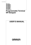
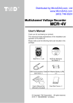
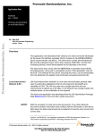
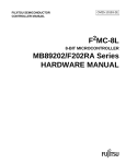
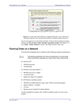
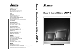
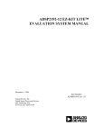
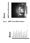
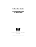
MB89P568 Demo Board
User’s Manual
Rev 1.0
Fujitsu Microelectronics America, Inc
Fujitsu Microelectronics America, Inc
Page 1
Revision History
Revision #
Date
Comments
1.0
07/12/2002
New Revision
Fujitsu Microelectronics America, Inc
Page 2
Warranty and Disclaimer
To the maximum extent permitted by applicable law, Fujitsu Microelectronics America Inc San Jose
restricts its warranties and its liability for the Product [MB89P568 LCD demo board Hardware and
Software Tools], its performance and any consequential damages, on the use of the Product in
accordance with (i) the terms of the License Agreement and the Sale and Purchase Agreement
under which agreements the Product has been delivered, (ii) the technical descriptions and (iii) all
accompanying written materials.
This product has been created to work in laboratory environment only. In addition, to the maximum
extent permitted by applicable law, Fujitsu Microelectronics America Inc San Jose disclaims all
warranties and liabilities for the performance of the Product and any consequential damages in
cases of unauthorized decompiling and/or reverse engineering and/or disassembling.
1. Fujitsu Microelectronics America Inc San Jose warrants that the Product will perform
substantially in accordance with the accompanying written materials [this manual] for a period
of 90 days form the date of receipt by the customer. Concerning the hardware
components of the Product, Fujitsu Microelectronics America Inc San Jose warrants that
the Product will be free from defects in material and workmanship under use and service
as specified in the accompanying written materials for a duration of 1 year from the date of
receipt by the customer.
2. Should a Product turn out to be defect, Fujitsu Microelectronics America Inc San Jose’s
Entire liability and the customer’s exclusive remedy shall be, at Fujitsu Microelectronics
America Inc San Jose ´s sole discretion, either return of the purchase price and the license
fee, or replacement of the Product or parts thereof, if the Product is returned to Fujitsu
Microelectronics America Inc San Jose in original packing and without further defects resulting
from the customer’s use or the transport. However, this warranty is excluded if the defect has
resulted from an accident not attributable to Fujitsu Microelectronics America Inc San Jose, or
abuse or misapplication attributable to the customer or any other third party not relating to
Fujitsu Microelectronics America Inc San Jose.
3. To the maximum extent permitted by applicable law Fujitsu Microelectronics America Inc San
Jose disclaims all other warranties, whether expressed or implied, in particular, but not limited
to, warranties of merchantability and fitness for a particular purpose for which the Product is
not designated.
4. To the maximum extent permitted by applicable law, Fujitsu Microelectronics America Inc San
Jose ´s and its suppliers´ liability is restricted to intention and gross negligence.
NO LIABILITY FOR CONSEQUENTIAL DAMAGES
To the maximum extent permitted by applicable law, in no event shall Fujitsu
Microelectronics America Inc San Jose and its suppliers be liable for any damages
whatsoever (including but without limitation, consequential and/or indirect damages for
personal injury, assets of substantial value, loss of profits, interruption of business
operation, loss of information, or any other monetary or pecuniary loss) arising from the use
of the Product.
Should one of the above stipulations be or become invalid and/or unenforceable, the remaining
stipulations shall stay in full effect.
Fujitsu Microelectronics America, Inc
Page 3
Table of contents
1
INTRODUCTION.........................................................................................................................6
1.1
1.2
1.3
1.4
2
OVERVIEW ...........................................................................................................................6
PURPOSE .............................................................................................................................6
FEATURES ............................................................................................................................6
DELIVERABLES .....................................................................................................................7
FUNCTIONAL DESCRIPTION ...................................................................................................9
2.1
FUNCTIONS OF SWITCHES .....................................................................................................9
2.1.1 Reset Switch ............................................................................................................... 10
2.1.2 Function Select Switch............................................................................................... 10
2.1.3 Enter switch ............................................................................................................... 11
2.1.4 ‘+’ or Increment switch ................................................................................................ 12
2.1.5 ‘—’ or Decrement switch ............................................................................................. 12
2.2
DISPLAY MESSAGE DESCRIPTION ........................................................................................12
2.3
GETTING STARTED .............................................................................................................15
2.3.1 Battery connections: ................................................................................................. 16
2.3.2
Display ...................................................................................................................... 16
2.3.2.1 Scrolling message display ........................................................................................ 16
2.3.2.3 Clock display............................................................................................................. 16
2.3.2.3 Alarm Time Display................................................................................................... 20
2.3.2.4 Calendar display ....................................................................................................... 26
2.3.2.5 Temperature display ................................................................................................. 34
2.3.2.6 Humidity display........................................................................................................ 35
2.4
NOTE .................................................................................................................................36
3
HARDWARE SPECIFICATIONS .............................................................................................37
3.1
3.2
3.3
3.4
3.5
3.6
4
POWER SUPPLY REQUIREMENT ...........................................................................................37
CLOCK ...............................................................................................................................38
LCD ..................................................................................................................................38
TEMPERATURE SENSOR ......................................................................................................38
HUMIDITY SENSOR .............................................................................................................39
BUZZER .............................................................................................................................39
SOFTWARE DETAILS .............................................................................................................41
4.1
LCD DEMO BOARD PROGRAM SPECIFICATIONS ....................................................................41
5
ACRONYMS .............................................................................................................................52
6
REFERENCES..........................................................................................................................53
7
APPENDIX: BILL OF MATERIALS ........................................................................................54
7.1 SCHEMATIC DIAGRAM OF MB89P568 DEMO BOARD ..................................................................55
7.2 MB89P568 DEMO PCB LAYOUT ..............................................................................................56
7.3 PCB TOP LAYER ......................................................................................................................57
Fujitsu Microelectronics America, Inc
Page 4
Figures and Tables
Figure 1: Functional Block Diagram of MB89P568 Demo Board...................................9
Figure 2: Menu Details.....................................................................................................11
Figure 3: Layout of Switches ..........................................................................................16
Figure 4: Board layout .....................................................................................................37
Table 1 ...............................................................................................................................12
Fujitsu Microelectronics America, Inc
Page 5
Introduction
1
1.1
Overview
This demo board shows the capabilities of the F2MC-8L series, popular MB89560 Microcontroller.
It is intended for low cost, low power and small information message display purpose.
The MB89P568 Demo Board makes use of MB89P568PFV-101. It is an OTP device of MB89560
series having LCD controller/driver on chip.
1.2
Purpose
The main purpose of designing this demo board is to show the following applications:
1) Hardware interface of Microcontroller with alphanumeric segmented LCD panel
2) Software application for using on chip LCD controller/driver
3) Hardware and software applications using resources available on microcontroller like A/D
converter, Watch pre-scalar, PPG and general purpose IO ports
4) Low power mode operation
1.3
Features
Following are the key application features of the demo board:
1) Six digit alphanumeric, 14 segment LCD display, with intensity adjustment.
2) Scrolling message display.
3) Display of Real time clock.
4) Alarm feature for clock.
5) Ambient temperature measurement and display in ºC.
6) Ambient relative humidity measurement and display in RH.
7) Calendar display- Day, Date, Month and Year can be displayed.
8) Hierarchical menu driven support for adjustment/display of the following parameters, using
pushbutton switches provided on the board:
a) Real time clock- Hour.
b) Real time clock-Minute.
c) Calendar day.
d) Calendar date.
e) Calendar months.
Fujitsu Microelectronics America, Inc
Page 6
f)
Calendar Year.
g) Alarm time.
h) Alarm stop.
i)
Temperature display.
j)
Humidity display.
9) For ease of use, supports both incrementing (+) and decrementing (-) parameter values, using
pushbutton switches.
2.1.1 Board Specifications
•
MB89P568 device with following features.
-
F2MC-8L series OTP device mounted on the board
-
By using foot print conversion adapter, the board can be used with In Circuit
Emulator. Following adapter is preferred for converting from bottom 0.5mm 80 pin
pitch to 0.80 mm 80 pin pitch.
80QF-80QF2-8L-UP
80QF-80SQF-8L-DWN
(This adapter can be from http://www. advintcorp.com/)
-
Device specifications:
ROM – 48K x 8 bits
Execution time: 0.4usec/ 10 MH
GPIO – 30 pins
10 bit x 8 ch ADC, 6 bit PPG, I2C, LCD driver on chip, UART, SIO
Supports low power modes. Operates using min & sub clock
-
1.4
Board operates using sub clock watch mode for low power operation.
Deliverables
•
MB89P568 Demo board cases in acrylic package with Mounting base
•
AAA Battery holder attached on rear side of the acrylic package
•
Three AAA Batteries
•
A buzzer diaphragm attached on back side of PCB for alarm beep
•
Quick Start Guide
•
CD ROM Containing
Fujitsu Microelectronics America, Inc
Page 7
1. Hardware manual and data sheets of MB89560 series
2. MB89P568 User’s Manual
3. Application note on “ Choosing right LCDs for use with MCU having on chip
LCDC”
4. Sample project files
Fujitsu Microelectronics America, Inc
Page 8
Functional description
2
Figure 1: Functional Block Diagram of MB89P568 Demo Board
6 DIGIT LCD
LCDC
4.5V
Buzzer
FUJITSU F2MC
Battery
MB89P568
CLOCK
Temp
10 MHZ
Sensor
ADC
Sub CLOCK
Humidity
32.76 KHZ
Sensor
GPIO
Function Selector Switches
Figure 1 shows the functional block diagram of MB89P568 demo board.
2.1
Functions of Switches
Including ‘RESET’, there are five switches provided on the board. The function of each switch is
explained in this section.
To enable user to initialize the board, select, adjust, input, control and display the parameters such
as time, calendar, alarm, temperature, and humidity following five types of switches are provided on
the board:
1. RESET: S1 (No color).
2. Function Select: S2 (Red color).
3. Enter: S3 (Blue color).
Fujitsu Microelectronics America, Inc
Page 9
4. ‘+’: S4 (White color).
5. ‘-- ‘: S5 (Black color).
For ease of use, four main functional switches on the board S2 to S5 are color coded in 4 different
colors, as described in the following sub-sections.
2.1.1 Reset Switch
Reset switch S1 is a simple (colorless) switch. It is provided near the microcontroller for ‘RESET’
operation. It also presets the parameter values to default initial values, for example the day, date
and time is set to ‘Tueday, January 1st, 2002, 12:00 AM respectively. User is expected to set day,
date and time values according his requirement, using the four functional switches as described in
this document.
2.1.2 Function Select Switch
It is a multi-function red pushbutton switch S2 , for selecting hierarchical functional menu that
functions depending on the functions selected. Figure 2: Menu Details shows menu details and
hierarchy. Following functions can be selected using this switch.
S2 ‘Function Select’ switch when pressed, toggles between only two modes. The two modes are:
1) Display mode: DSP_MD
2) Adjust mode: ADJ_MD
To select any of the above modes press ‘Function Select’ Red switch. For the first time, ‘Display
mode’ appears on LCD. When pressed the same for second time ‘Adjust mode’ appears on the
display. For selecting one of the modes, press blue switch ‘Enter’. If the parameter Display mode is
selected, the Menu appears in sequence as shown below.
The function of this ‘Display mode’ is to view parameters like temperature, Humidity, calendar and
alarm time whenever required according to user requirement.
When ‘Adjust Mode’ is selected by pressing blue switch ‘Enter’, the following parameter can be
changed according to user requirement.
1) Hour value
2) Minute Value
3) Alarm hour value
4) Alarm minute value
Refer to section 2.3 ‘Getting started’ for the detailed procedure.
Fujitsu Microelectronics America, Inc
Page 10
Figure 2: Menu Details
Function Select-switch S2
Modes
ADJ MD
DSP MD
Menu
Switch S4
1. DP DAY
1. MN ADJ
2. DP_DAT
2. HR ADJ
3. DP_TMP
3. DY ADJ
4. DP_HUM
4. DT ADJ
5. DP_ALT
5. MT ADJ
6. DP_TIM
6. YR_ADJ
+
Switch S5
--
7. AM_ADJ
8. AH_ADJ
9. AL_E_D
ENTER
Switch S3
2.1.3 Enter switch
Enter switch dual function switch. It is used for two purposes.
•
Pressing Blue pushbutton switch S3 is for accepting the selected functions of the menu.
Fujitsu Microelectronics America, Inc
Page 11
•
Pressing this switch stops alarm sound.
2.1.4 ‘+’ or Increment switch
This White switch has two functions.
1) The switch is for selecting the menu options listed in above Figure 1 in increasing sequence
from 1 to 9.
2) The switch is also for incrementing the value of the selected parameter. For example, the switch
is used to increment the hour, minute, date, month, year and day value.
2.1.5 ‘—’ or Decrement switch
This black switch has two functions.
1) The switch is for selecting the menu options listed in above Figure 1 in decreasing sequence
from 9 to 1.
2) The switch is also for decrementing the value of the selected parameter. For example, the switch
is used to decrement the hour, minute, date, month, year and day value.
2.2 Display Message Description
Following Table 1 describes Display messages. Since MCU is capable of interfacing 24 X 4
elements of LCD, it is possible to make use of only 6 digits (each 14 segment alphanumeric) for
display application. Messages are abbreviated as described below.
Table 2
Abbreviation
of Message
Displayed on
LCD
Meaning of
Message
Description of Message
Function Adjust
Messages
ADJ_MD
Adjust Mode
Indicates the mode in which the menu of parameters
to be adjusted has been selected
DSP_MD
Display Mode
Indicates the mode in which the menu of parameters
to be displayed has been selected
SL_ADJ
Select Adjust
mode
This message indicates that ‘Adjust mode’ has been
selected
Fujitsu Microelectronics America, Inc
Page 12
Abbreviation
of Message
Displayed on
LCD
Meaning of
Message
Description of Message
HR_ADJ
Hour Adjust
This message indicates that ‘Hour’ parameter of the
clock has to be adjusted.
MN_ADJ
Minute Adjust
This message indicates that ‘Minute’ parameter of
the clock has to be adjusted.
AH_ADJ
Alarm Hour
Adjust
This message indicates that ‘Alarm Hour’ has to be
adjusted.
AM_ADJ
Alarm Minute
Adjust
This message indicates that ‘Alarm Minute’ has to be
adjusted.
AL_E_D
Alarm
Enable/Disable
This message indicates that alarm sound has to be
enabled or disabled after setting alarm time.
DY_ADJ
Day Adjust
This message indicates that ‘Day’ of calendar week
has to be adjusted.
DT_ADJ
Date Adjust
This message indicates that ‘Date’ of calendar week
has to be adjusted.
MT_ADJ
Month Adjust
This message indicates that ‘Month’ of calendar year
has to be adjusted.
YR_ADJ
Year Adjust
This message indicates that ‘Year’ of calendar has to
be adjusted.
Messages for
Displaying
Parameters
Fujitsu Microelectronics America, Inc
Page 13
Abbreviation
of Message
Displayed on
LCD
Meaning of
Message
Description of Message
DP_TMP
Display
Temperature
This message indicates user that display of
Temperature in ‘ºF’ can be selected.
DP_HUM
Display
Humidity
This message indicates that display of Humidity in
‘RH’ can be selected
DP_ALT
Display Alarm
Time
This message indicates that display of previously set
‘Alarm Time’ can be viewed.
DP_DAY
Display Day
This message indicates that display of previously set
calendar ‘Day’ can be viewed.
DP_DAT
Display Date
This message indicates that display of previously set
calendar ‘Date’ can be viewed.
DP_TIM
Display Time
This message indicates that display of latest ‘Time’
can be viewed.
AL_STP
Alarm Stop
This message indicates that Alarm Beep has been
stopped
AL_ENB
Alarm Enable
This message indicates that Alarm has been enabled
AL_DSB
Alarm Disable
This message indicates that Alarm has been disabled. Even
if Alarm time has been set, it will not produce alarm beep
sound, since user might have already disabled the alarm by
pressing/selecting AL_E_D
-DONE_
Selection done
This message indicates current task has been
completed and done.
Fujitsu Microelectronics America, Inc
Page 14
Abbreviation
of Message
Displayed on
LCD
INVALD
Meaning of
Message
Invalid
Description of Message
This message indicates pushbutton switch pressed
is ‘Invalid’
Status
messages
ALT_IS
Alarm is
This message appears just before the display of
Alarm Time
TIM_IS
Time is
This message appears just before the display of
Time
TMP_IS
Temperature is
This message appears just before the display of
Temperature.
HUMIDIT
Humidity
This message appears just before the display of the
parameter ‘Humidity’
DAY_IS
Day is
This message appears just before the display of Day
of the week.
DAT_IS
Date is
This message appears just before the display of
Date.
2.3 Getting Started
MB89P568 Demo board packaged in an acrylic case includes an acrylic stand to keep the board in
comfortable position for using it as a table top clock. It also includes three AAA batteries.
Fujitsu Microelectronics America, Inc
Page 15
2.3.1 Battery connections:
Rear side of the board is equipped with a battery holder. Three AAA batteries each of 1.5V to be
inserted in the battery holder. While inserting batteries in the battery holder, take care of ‘+’ and ‘‘markings on the battery holder. Once batteries are inserted in correct position, demo board is
ready to be used.
2.3.2 Display
Once board gets 4.5V supply from batteries, press ‘RESET’ (S1) pushbutton switch to ensure that
microcontroller and other devices on the board are initialized.
2.3.2.1 Scrolling message display
Once the board is initialized, you will be able to see welcome greetings ‘WELCOME TO FUJITSU
MICROELECTRONICS AMERICA INC ‘message starts scrolling on 6 digit LCD panel.
WELCOME TO F
This scrolling message later periodically repeats once per around every 30 minutes.
2.3.2.3
Clock display
After the end of scrolling message, clock display starts. Default clock start at 12.00am as shown
below.
12:00 AM
2.3.2.3.1 CLOCK ADJUSTMENT
Follow below procedure to adjust the clock to the required time.
Adjustment of ‘Time Hour’: Diagram of functional switches is shown in Figure 3: Layout
of Switches3
12:00 AM
Figure 3: Layout of Switches
Function Select
Fujitsu Microelectronics America, Inc
Enter
Page 16
S2
S3
+
S4
-S5
1. To adjust ‘Time Hour’ parameter, press red push button switch ‘Function Select’ (Switch S2).
‘ADJ_MOD’ message appears on LCD. This means the board is now in ‘Adjust mode’.
ADJ_MOD
S2
Now user will be able to select the parameter that he is interested to change.
2. Now press blue switch ’Enter’ (Switch S3) to indicate the acceptance for being in that mode.
S3
3. Message ‘SL_ADJ’ appears on display.
SL_ADJ
Press white push button switch ‘+’ (switch S4) or black push button switch ‘__’ (switch S5) till
message ‘HR_ADJ’ appears on display.
+
OR
S4
-S5
HR_ADJ
4. Now press blue push button switch ‘Enter’. ‘SELCTD’ appears on display.
S3
Fujitsu Microelectronics America, Inc
SELCTD
Page 17
5. Press white pushbutton switch ‘+’ to increase the ‘Hour’ value of time as required.
OR
+
S4
-S5
1.00PM
For example, display appears as above, while adjusting hour of time
3. Press blue pushbutton switch ‘Enter’ to indicate the end of adjustment. ‘-DONE-‘ message
appears on display. Depending on the adjusted time, AM changes to PM or vise versa.
S3
-DONE-
Adjustment of ‘Time Minute’:
1. To adjust ‘Time Minute’ parameter, press red push button switch ‘Function Select’ (Switch S2).
‘SP_MOD’ message appears on LCD. This means the board is now in ‘Adjust parameter’ mode.
S2
ADJ_MD
Now user will be able to select the parameter that he is interested to change.
2. Now press blue switch’ Enter’ (Switch S3) to indicate the acceptance for being in that mode.
S3
3. Message ‘SL_ADJ’ appears on display.
SL_ADJ
Press white push button switch ‘+’ (switch S4) or black push button switch ‘__’ (switch S5) till
message ‘MN_ADJ’ appears on display.
.
+
OR
S4
-S5
MN_ADJ
Fujitsu Microelectronics America, Inc
Page 18
4. Now press blue push button switch ‘Enter’. ‘SELCTD’ appears on display.
SELCTD
S3
5. Press white pushbutton switch ‘+’ to increase the ‘minute’ value of time as required.
+
OR
S4
-S5
1.10PM
For example, display appears as above, while adjusting minute value of time
6. Press blue pushbutton switch ‘Enter’ to indicate the end of adjustment. ‘-DONE-‘ message
appears on display.
S3
-DONE-
2.3.2.3.2 DISPLAY OF TIME
This is an addition option to display time. Since by default Time is always displayed, this might be
used very rarely. Please refer following steps to display the time.
1. Press red push button switch ‘Function Select’ (Switch S2).
‘DSP_MOD’ message appears on LCD. This means the board is now in ‘Display mode’ and is
ready to display selected parameters.
S2
DSP_MD
Now user will be able to select the parameter that he is interested to change.
2. Now press blue switch’ Enter’ (Switch S3) to indicate the acceptance for being in that mode.
S3
Fujitsu Microelectronics America, Inc
Page 19
3. Message ‘SL_DSP’ appears on display. Press white push button switch ‘+’ (switch S4) or black
push button switch ‘__’ (switch S5) till message ‘DP_TIM’ appears on display.
SL_DSP
+
OR
S4
-S5
DP_TIM
4. Now press blue push button switch ‘Enter’
S3
5. Following message and then time appear as below.
TIM_IS
1.10PM
6. Press blue pushbutton switch ‘Enter’ to indicate the end of display mode.
S3
2.3.2.3
Alarm Time Display
Alarm time by default is adjusted to 6.00 AM. If time is 6.00AM, and also if Alarm is Enabled by
selecting ‘AL_ENB’ function, then only alarm beeps.
6:00 AM
♫♫♫♫
2.3.2.3.1 ALARM ADJUSTMENT
Follow below procedure to adjust the alarm to the required time.
Adjustment of ‘Alarm Hour’: Diagram of functional switches is shown in Figure 3: Layout
of Switches3.
Fujitsu Microelectronics America, Inc
Page 20
1. To adjust ‘Alarm Hour’ parameter, press red push button switch ‘Function Select’ (Switch S2).
‘ADJ_MD’ message appears on LCD. This means the board is now in ‘Adjust parameter’ mode.
S2
ADJ_MD
Now user will be able to select the parameter that he is interested to change.
2. Now press blue switch’ Enter’ (Switch S3) to indicate the acceptance for being in that mode.
S3
3.
Message ‘SL_ADJ’ appears on display..
SL_ADJ
Press white push button switch ‘+’ (switch S4) or black push button switch ‘__’ (switch S5) till
message ‘AH_ADJ’ appears on display
OR
+
S4
-S5
AH_ADJ
4. Now press blue push button switch ‘Enter’. ‘SELCTD’ appears on display.
SELCTD
S3
5. Press white pushbutton switch ‘+’ to increase the ‘Hour’ value of alarm time as required.
+
OR
S4
-S5
7.00AM
Fujitsu Microelectronics America, Inc
Page 21
For example, display appears as above, while adjusting hour of time
6. Press blue pushbutton switch ‘Enter’ to indicate the end of adjustment. ‘-DONE-‘ message
appears on display. Depending on the adjusted time, AM changes to PM or vise versa.
S3
-DONE-
Adjustment of ‘Alarm Minute’:
1. To adjust ‘Time Minute’ parameter, press red push button switch ‘Function Select’ (Switch S2).
‘ADJ_MD’ message appears on LCD. This means the board is now in ‘Select parameter’ mode.
S2
ADJ_MD
Now user will be able to select the parameter that he is interested to change.
2. Now press blue switch’ Enter’ (Switch S3) to indicate the acceptance for being in that mode.
S3
3.
Message ‘SL_ADJ’ appears on display.
SL_ADJ
Press white push button switch ‘+’ (switch S4) or black push button switch ‘__’ (switch S5) till
message ‘AM_ADJ’ appears on display.
+
OR
S4
-S5
AM_ADJ
4. Now press blue push button switch ‘Enter’. ‘SELCTD’ appears on display
S3
SELCTD
.
5. Press white pushbutton switch ‘+’ to increase the ‘minute’ value of alarm time as required.
Fujitsu Microelectronics America, Inc
Page 22
+
OR
--
S4
S5
7.10AM
For example, display appears as above, while adjusting minute value of time
6. Press blue pushbutton switch ‘Enter’ to indicate the end of adjustment. ‘-DONE-‘ message
appears on display.
S3
-DONE-
Adjusted Alarm Enable
1. To adjust ‘Time Minute’ parameter, press red push button switch ‘Function Select’ (Switch S2).
‘ADJ_MD’ message appears on LCD. This means the board is now in ‘Adjust parameter’ mode.
ADJ_MD
S2
Now user will be able to select the parameter that he is interested to change.
2. Now press blue switch’ Enter’ (Switch S3) to indicate the acceptance for being in that mode.
S3
3.
Message ‘SL_ADJ’ appears on display.
SL_ADJ
Press white push button switch ‘+’ (switch S4) or black push button switch ‘__’ (switch S5) till
message ‘AL_E_D’ appears on display.
+
OR
S4
-S5
AL_E_D
Fujitsu Microelectronics America, Inc
Page 23
4. Now press blue push button switch ‘Enter’. ‘SELCTD’ appears on display.
S3
SELCTD
5. Press white pushbutton switch ‘+’ to select the option for enabling alarm
OR
+
--
S4
S5
AL_ENB
For example, display appears as above.
6. Press blue pushbutton switch ‘Enter’ to indicate the end of adjustment. ‘-DONE-‘ message
appears on display.
-DONE-
S3
Adjusted Alarm Disable
1. To adjust ‘Time Minute’ parameter, press red push button switch ‘Function Select’ (Switch S2).
‘ADJ_MD’ message appears on LCD. This means the board is now in ‘Select parameter’ mode.
S2
ADJ_MD
Now user will be able to select the parameter that he is interested to change.
2. Now press blue switch’ Enter’ (Switch S3) to indicate the acceptance for being in that mode.
S3
3.
Message ‘SL_ADJ’ appears on display. Press white push button switch ‘+’ (switch S4) or
black push button switch ‘__’ (switch S5) till message ‘AL_E_D’ appears on display.
SL_ADJ
+
OR
S4
-S5
AL_E_D
Fujitsu Microelectronics America, Inc
Page 24
4. Now press blue push button switch ‘Enter’. ‘SELCTD’ appears on display.
S3
SELCTD
5. Press white pushbutton switch ‘+’ to select the option for disabling alarm.
+
OR
--
S4
S5
AL_DIS
For example, display appears as above, while disabling the Alarm, so that it will not make alarm
beep sound.
6. Press blue pushbutton switch ‘Enter’ to indicate the end of adjustment. ‘-DONE-‘ message
appears on display.
S3
-DONE-
2.3.2.3.1 DISPLAY OF ALARM TIME
This feature is to display already set alarm time. Please refer following steps to display the alarm
time.
1. Press red push button switch ‘Function Select’ (Switch S2).
‘DSP_MOD’ message appears on LCD. This means the board is now in ‘Display mode’ and is
ready to display selected parameters.
S2
DSP_MD
Now user will be able to select the parameter that he is interested to change.
2. Now press blue switch’ Enter’ (Switch S3) to indicate the acceptance for being in that mode.
S3
3. Message ‘SL_DSP’ appears on display. Press white push button switch ‘+’ (switch S4) or black
push button switch ‘__’ (switch S5) till message ‘DP_TIM’ appears on display.
Fujitsu Microelectronics America, Inc
Page 25
SL_DSP
OR
+
S4
-S5
DP_ALT
4. Now press blue push button switch ‘Enter’
S3
5. Following message and time appear as below.
ALT_IS
1.10PM
6. Press blue pushbutton switch ‘Enter’ to indicate the end of display mode.
S3
2.3.2.4 Calendar display
Board has the feature to display day, date, month and year. Default date set is 01.01.02 that is
January 1st, 2002 and day is Tuesday.
01.01.02
TUEDAY
2.3.2.4.1 CALENDAR ADJUSTMENT
Below is the procedure for changing required day, date, month and year.
Adjustment of ‘Day’: Diagram of functional switches is shown in Figure 3: Layout of
Switches
1. To adjust ‘Day’ parameter, press red push button switch ‘Function Select’ (Switch S2).
Fujitsu Microelectronics America, Inc
Page 26
‘ADJ_MD’ message appears on LCD. This means the board is now in ‘Adjust parameter’ mode.
S2
ADJ_MD
Now user will be able to select the parameter that he is interested to change.
2. Now press blue switch’ Enter’ (Switch S3) to indicate the acceptance for being in that mode.
S3
3.
Message ‘SL_ADJ’ appears on display.
SL_ADJ
Press white push button switch ‘+’ (switch S4) or black push button switch ‘__’ (switch S5) till
message ‘DY_ADJ’ appears on display.
+
OR
--
S4
S5
DY_ADJ
4. Now press blue push button switch ‘Enter’. ‘SELCTD’ appears on display.
SELCTD
S3
5. Press white pushbutton switch ‘+’ to choose the required ‘Day’ of a week.
+
OR
S4
-S5
FRIDAY
For example, display appears as above, while adjusting day to ‘FRIDAY’
Fujitsu Microelectronics America, Inc
Page 27
6. Press blue pushbutton switch ‘Enter’ to indicate the end of adjustment. ‘-DONE-‘ message
appears on display.
-DONE-
S3
Adjustment of ‘Date’:
1. To adjust ‘Day’ parameter, press red push button switch ‘Function Select’ (Switch S2).
‘ADJ_MD’ message appears on LCD. This means the board is now in ‘Select parameter’ mode.
ADJ_MD
S2
Now user will be able to select the parameter that he is interested to change.
2. Now press blue switch’ Enter’ (Switch S3) to indicate the acceptance for being in that mode.
S3
3.
Message ‘SL_ADJ’ appears on display.
SL_ADJ
Press white push button switch ‘+’ (switch S4) or black push button switch ‘__’ (switch S5) till
message ‘DT_ADJ’ appears on display.
+
OR
S4
-S5
DT-ADJ
4. Now press blue push button switch ‘Enter’. ‘SELCTD’ appears on display.
S3
SELCTD
5. Press white pushbutton switch ‘+’ to choose the required ‘Date’ of the month.
+
OR
S4
-S5
01.19.02
Fujitsu Microelectronics America, Inc
Page 28
For example, display appears as above, while adjusting date to 19th.
6. Press blue pushbutton switch ‘Enter’ to indicate the end of adjustment. ‘-DONE-‘ message
appears on display.
S3
-DONE-
Adjustment of ‘Month’
1. To adjust ‘Day’ parameter, press red push button switch ‘Function Select’ (Switch S2).
‘ADJ_MD’ message appears on LCD. This means the board is now in ‘Adjust parameter’ mode.
ADJ_MD
S2
Now user will be able to select the parameter that he is interested to change.
2. Now press blue switch’ Enter’ (Switch S3) to indicate the acceptance for being in that mode.
S3
3. Message ‘SL_ADJ’ appears on display.
SL_ADJ
Press white push button switch ‘+’ (switch S4) or black push button switch ‘__’ (switch S5) till
message ‘MT_ADJ’ appears on display.
OR
+
S4
-S5
MT_ADJ
4. Now press blue push button switch ‘Enter’. ‘SELCTD’ appears on display.
S3
SELCTD
Fujitsu Microelectronics America, Inc
Page 29
5. Press white pushbutton switch ‘+’ to choose the required ‘month’ of the year.
+
OR
--
S4
S5
07.19.02
For example, display appears as above, while adjusting month to’7’.
6. Press blue pushbutton switch ‘Enter’ to indicate the end of adjustment. ‘-DONE-‘ message
appears on display.
S3
-DONEAdjustment of ‘Year’
1. To adjust ‘Day’ parameter, press red push button switch ‘Function Select’ (Switch S2).
‘ADJ_MD’ message appears on LCD. This means the board is now in ‘Adjust parameter’ mode.
ADJ_MD
S2
Now user will be able to select the parameter that he is interested to change.
2. Now press blue switch’ Enter’ (Switch S3) to indicate the acceptance for being in that mode.
S3
3.
Message ‘SL_ADJ’ appears on display.
SL_ADJ
Press white push button switch ‘+’ (switch S4) or black push button switch ‘__’ (switch S5) till
message ‘YR_ADJ’ appears on display
Fujitsu Microelectronics America, Inc
Page 30
+
OR
S4
-S5
YR_ADJ
4. Now press blue push button switch ‘Enter’. ‘SELCTD’ appears on display.
SELCTD
S3
5. Press white pushbutton switch ‘+’ to choose the required year.
+
OR
S4
-S5
07.04.02
For example, display appears as above, while adjusting year. If change of year value is not
required, just press ‘Enter’.
6. Press blue pushbutton switch ‘Enter’ to indicate the end of adjustment. ‘-DONE-‘ message
appears on display.
S3
-DONE-
2.3.2.3.1 DISPLAY OF CALENDAR
This is an additional feature provided to display previously set Day and Date.
Display of Day
1. Press red push button switch ‘Function Select’ (Switch S2). ‘DSP_MOD’ message appears on
LCD. This means the board is now in ‘Display mode’ and is ready to display selected parameters.
S2
DSP_MD
Now user will be able to select the parameter that he is interested to change.
2. Now press blue switch’ Enter’ (Switch S3) to indicate the acceptance for being in that mode.
Fujitsu Microelectronics America, Inc
Page 31
S3
3. Message ‘SL_DSP’ appears on display.
SL_DSP
Press white push button switch ‘+’ (switch S4) or black push button switch ‘__’ (switch S5) till
message ‘DP_DAY’ appears on display.
+
OR
S4
-S5
DP_DAY
4. Now press blue push button switch ‘Enter’
S3
5. Following message and time appear as below.
DAY_IS
FRIDAY
6. Press blue pushbutton switch ‘Enter’ to indicate the end of display mode.
S3
Display of Date
1. Press red push button switch ‘Function Select’ (Switch S2). ‘DSP_MOD’ message appears on
LCD. This means the board is now in ‘Display mode’ and is ready to display selected parameters.
DSP_MD
Fujitsu Microelectronics America, Inc
Page 32
S2
Now user will be able to select the parameter that he is interested to change.
2. Now press blue switch’ Enter’ (Switch S3) to indicate the acceptance for being in that mode.
S3
3. Message ‘SL_DSP’ appears on display.
SL_DSP
Press white push button switch ‘+’ (switch S4) or black push button switch ‘__’ (switch S5) till
message ‘DP_DAT’ appears on display.
OR
+
S4
-S5
DP_DAT
4. Now press blue push button switch ‘Enter’
S3
5. Following message and time appear as below.
DAT_IS
07.07.02
6. Press blue pushbutton switch ‘Enter’ to indicate the end of display mode.
S3
Fujitsu Microelectronics America, Inc
Page 33
2.3.2.5 Temperature display
Temperature in ºC is displayed whenever user wants to display temperature by following below
procedure.
1. Press red push button switch ‘Function Select’ (Switch S2). ‘DSP_MOD’ message appears on
LCD. This means the board is now in ‘Display mode’ and is ready to display selected parameters.
S2
DSP_MD
Now user will be able to select the parameter that he is interested to change.
2. Now press blue switch’ Enter’ (Switch S3) to indicate the acceptance for being in that mode.
S3
3. Message ‘SL_DSP’ appears on display.
SL_DSP
Press white push button switch ‘+’ (switch S4) or black push button switch ‘__’ (switch S5) till
message ‘DP_TMP’ appears on display.
+
OR
S4
-S5
DP_TMP
4. Now press blue push button switch ‘Enter’
S3
Fujitsu Microelectronics America, Inc
Page 34
5. Following message and time appear as below.
TEMP
20.2ºC
6. Press blue pushbutton switch ‘Enter’ to indicate the end of display mode.
S3
2.3.2.6 Humidity display
Humidity in RH is displayed whenever user wants to display humidity by following below procedure.
1. Press red push button switch ‘Function Select’ (Switch S2). ‘DSP_MOD’ message appears on
LCD. This means the board is now in ‘Display mode’ and is ready to display selected parameters.
DSP_MD
S2
Now user will be able to select the parameter that he is interested to change.
2. Now press blue switch’ Enter’ (Switch S3) to indicate the acceptance for being in that mode.
S3
3. Message ‘SL_DSP’ appears on display.
SL_DSP
Press white push button switch ‘+’ (switch S4) or black push button switch ‘__’ (switch S5) till
message ‘HUMIDTY’ appears on display.
+
OR
S4
-S5
HUMIDTY
Fujitsu Microelectronics America, Inc
Page 35
4. Now press blue push button switch ‘Enter’
S3
5. Following message and time appear as below.
HUMIDTY
30.0RH
6. Press blue pushbutton switch ‘Enter’ to indicate the end of display mode.
S3
2.4 Note
•
In each of the above cases of adjustment/display of parameters, when push button switch
other than mentioned in above sequences ahs been pressed, message ‘Invalid’ appears on
LCD. This indicates that invalid key has been pressed.
INVLID
.
In such cases, just press ‘Enter’ key. ‘Done’ message appears and display returns to
normal Clock mode.
•
Humidity and temperature measurement values may not be very accurate and may vary
due to variation in supply voltage, battery drain, and variation in AVref to A/D converter of
MCU and also due to nonlinear output of sensors. Humidity and temperature measurement
is meant to show the capabilities of MCU for such kind of applications.
•
VR1 is provided on the board for intensity adjustment of LCD. If battery voltage starts
falling, intensity might reduce. In such case VR1 can be used. Clock and Calendar
functions even with 3V battery or regulated supply. But note that VR1 should be adjusted in
such case. But with 3V power supply humidity and temperature measurements can not be
made due to internal A/D of MCU voltage requirement.
Fujitsu Microelectronics America, Inc
Page 36
Hardware Specifications
3
3.1
Power Supply Requirement
Three AAA batteries provide 4.5V power supply voltage to the board. There is an option for
mounting DC power jack X1 on the board instead of batteries. Then care should be taken that the
regulated power supply of 4.5 V should be supplied after disconnecting wire leads to battery or
making use of ON/OFF switch on battery holder residing on backside of the board . Power indicator
‘D1’ green LED glows only when jumper ‘J1’ is shorted. For providing higher resolution for
displaying temperature and humidity, the internal A/D converter of the micro-controller requires
minimum voltage higher than 3.2V. Therefore, 4.5V regulated power supply or 4.5 V battery output
meets the voltage requirements The MB89P568
Demo board with above features supports the FPT-80P-M05 square QFP 80 pin, 14x14mm
package with 0.5mm pitch
Figure 4: Board layout
Fujitsu Microelectronics America, Inc
Page 37
Error! Reference source not found. shows detailed board layout where all mounted devices are
marked.
3.2
Clock
The board operates with high-speed main clock of 10MHz and low speed sub clock of 32.768 KHz.
To implement the real-time clock watch pre-scalar is used. Watch pre-scalar provides interval timer
functions. It uses a 17 bit free running counter, which counts in sync with a sub clock. Program
interval time divided clock output is selected as 1sec using sub clock source oscillation. The entire
program uses main clock except watch pre-scalar and LCD controller.
Enable and stop of main and sub clock oscillations are controlled by clock and stop modes. The
board functions in low power sleep mode. Switching from normal to low power mode is taken care
in software.
3.3
LCD
LCD used is 14-segment alphanumeric display VIM-878-RC-S. MB89P568 MCU is having on chip
24 x 4 pixels LCD controller/Driver. The chosen LCD panel is having 128 pixels ( 8 digits and each
digit has 14 segments for displaying alphanumeric characters). However, MB89P568 is capable of
driving 96 pixels, maximum of 6 digits of the LCD panel can be utilized for displaying the message.
Refer APPENDIX for schematic diagram. 24 segments and 4 common pins of the LCD are directly
connected to corresponding 24 segment and 4 common pins of MCU MB89P568. LCD is suitable
only for operating in 1/3 bias, ¼ duty ratio, and multiplex mode with MCU. 10Kohms potentiometer
is connected to V3 drive pin of MCU for intensity adjustment of the LCD.
For electrical specifications refer chapter 6.Following are the electrical specifications.
Characteristics:
3.4
•
Manufacturer: Varitronix
•
Fourteen segment alphanumeric monochrome display.
•
Multiplex LV type with commercial TN display.
•
Multiplex drive, 1/3 bias, ¼ duty ratio, no backlight
•
Viewing angle 6 O’ clock mode
•
Since LV, operating voltage is typically 3.2 V. To maintain this voltage to drive LCD,
VR1 is provided on the board.
Temperature Sensor
Temperature sensor U2 used along with the board is LM19-CIZ. This is a precision analog output
CMOS temperature sensor that operates over -67ºF to 266ºF range. Analog linear output of sensor
is connected to A/D converter AN0 input for conversion to digital value. Since the sensor is low
cost, low power and output of the sensor being analog linear, it suits for our application. This sensor
is used for measuring ambient temperature in ºF.
Fujitsu Microelectronics America, Inc
Page 38
The LM19 is a precision analog output CMOS integrated-circuit temperature sensor that operates
over a -55°C to +130°C temperature range. The power supply operating range is +2.4 V to +5.5 V.
The transfer function of LM19 is predominately linear, yet has a slight predictable parabolic
curvature. The accuracy of the LM19 when specified to a parabolic transfer function is ±2.5°C at an
ambient temperature of +30°C. The temperature error increases linearly and reaches a maximum
of ±3.8°C at the temperature range extremes. The power supply voltage affects the temperature
range. At a power supply voltage of 2.7 V to 5.5 V the temperature range extremes are +130°C and
-55°C. Decreasing the power supply voltage to 2.4 V changes the negative extreme to -30°C, while
the positive remains at +130°C. The LM19's quiescent current is less than 10 µA. Therefore, selfheating is less than 0.02°C in still air.
Features
•
Rated for full -55°C to +130°C range
•
Available in a TO-92 package
•
Predictable curvature error
•
Manufacturer: National Semiconductor
For detailed package and specifications refer chapter 6
3.5
Humidity Sensor
Humidity Sensor U5 used is HIH-3630-101. This Relative humidity sensor from Honey well delivers
high quality sensing performance. It is rugged, low cost and perfect for battery-powered systems
since current drawn is only 200uA. Linear analog output of sensor is connected to AN1 input of A/D
converter for conversion to digital value and also for displaying the same in %RH units. For details
and specifications of this sensor, refer chapter 6.
Features:
3.6
•
Linear output voltage versus %RH
•
Low power, High accuracy
•
Fast response time, stable
•
Molded thermo set plastic housing
Buzzer
PPG of MCU is used for producing alarm sound. The software takes care of initializing PPG.
Buzzer is connected to PPG2 output pin of the MCU. The alarm time could be adjusted by pressing
the red push button switch ‘Function select’.
Buzzer EE27A-39A is piezo-ceramic buzzer diaphragm from FDK. FDK piezoceramic buzzers
generate sound through the bending vibrations of a thin metal plate adhered to a piezoceramic
disc. These buzzers feature low power consumption, a safe, spark-free and non-contact structure,
and a small size and light weight for an easy mounting to printed circuit boards. It is external drive
Fujitsu Microelectronics America, Inc
Page 39
type having resonant frequency of 3.9 KHz suitable to use with MCU having PPG macro for
generating sound.
Package
Electrical Specifications of EE27A-39A:
Resonant Frequency: 3.9 KHz
Maximum input voltage: 30V, capacitance: 20,000 pF
Metal plate material: Brass
Weight: 1.6grams
Metal plate outer Diameter: 27mm
Fujitsu Microelectronics America, Inc
Page 40
Software Details
4
4.1
LCD Demo Board program specifications
The specifications of the LCD demo program for MB89P568 assume the following conditions.
•
MCU series: MB89560
•
MCU MB89P568PFV-101 : FPT - 80P-M05 Package, without booster and with internal
voltage divider.
•
-
Main Clock.: 10MHz
-
Sub Clock: 32.768KHz
LCD Display Ports
- SEG00 to SEG07 ……………….. Segment output ports
- P50/SEG08 to P57/SEG15 ……… Segment output ports
- P60/SEG16 to P67/SEG23 ……… Segment output ports
- COM0 to COM3 ………………. Common output ports
Operation outline:
To implement the clock demo on LCD display, watch pre-scalar is used. Watch pre-scalar
provides interval timer functions. It uses a 17 bit free run counter that counts in sync with a sub
clock. In this program, interval time divided clock output is selected as 1sec using sub clock
source oscillation. The entire program uses main clock except watch pre-scalar and LCD
controller.
1) Important Registers and RAM locations
Address
Register
Function
07H
SYCC
system clock control Register
0BH
WPCR
Watch pre-scalar control register
PDR5
port 5 data register for segments
PDR6
port 6 data register for segments
60 to 6BH
VRAM
LCD display data ram register
5BH
LCR1
LCD control register 1
5CH
LCR2
LCD control register 2
5DH
LCR3
LCD control registers 3
5EH
LDR1
LCD static control register
Fujitsu Microelectronics America, Inc
Page 41
7BH
ILR1
Interrupt level set register
7DH
ILR3
Interrupt level set register
3FH
EIC1
External Interrupt Control Register1
40H
EIC2
External Interrupt Control Register2
38H
RCR21
PPG Control Registers
3AH
RCR22
39H
RCR23
3BH
RCR24
34H
ADC1
35H
ADC2
36H
ADDL
37H
ADDH
ADC control registers
ADC data registers
2) Register Initialization
- Initializing the system clock control register SYCC
SYCC = 0x8F = 10001111: CS0: System operation clock = 0.2us
CS1
SCS: Sets the system clock to main mode
WT0: Oscillation stabilization time = 1.6ms
WT1
SCM: System clock monitor bits
- Initializing Watch pre scalar
WPCR = 0x46 =01000110: WCLR: clear
WS0: 1sec interval interrupt
WS1
WS1
WIE: Enable interrupt
WIF: clear watch interrupt flag
Fujitsu Microelectronics America, Inc
Page 42
- Initializing LCD control registers
LCR1 = 0xEE = 11101110: FP0: Frame cycle selection bits = 64Hz
FP1
MS0: ¼ duty ratio
MS1
BK: Display un-blank
VSEL: Drive supply voltage control bit- Internal
Resistor
LCDEN: Run in watch mode
CSD: Subclock
LCR2 = 0xC2= 11000010: FPS0: 64Hz
FPS1
LCS0: Static segment off
LCS1
LCS2
LCS3
LCSEN: Run in watch mode
CSS: Subclock
LCR3 = 0x10 = 00010000: LCD0: Segment 0-23 sel
LCD1
LCD2
LCD3
LCD4
LCS: reserved bit set ‘0’
LDR1 = 0x00 = not in static display mode
Fujitsu Microelectronics America, Inc
Page 43
-
Initialization of Interrupt level setting registers
ILR1 = 0xF8 =111110000 = IRQ0 at level1
IRQ1 at level2
IRQ3 and IRQ4 at level3
ILR3 = 0xBC = 10111100 = Watch pre scalar interrupt at level1
ADC at level2
IRQ9 and IRQA at default level3
- Initializing External interrupt control register
EIC1= 0x44 = 01000100 = clear interrupt request flag
Select falling edge
EIC2 = 0x44 = 01000100
- Initializing PPG Control Register
RCR21 = 0x1C= 00011100 = HSC0 to HCC5: High pulse compare value
RCK0, RCK1: 1 instr cycle
RCR22 = 0x02 = 00000010 = HSC6 to HSC11: High pulse width setting
bits
RCR23 = 0x38 = 00111000 = SCL0 to SCL5: cycles compare value
RCR24 = 0x04 = 00000100 = SCL6 to SCL11: cycle setting bits
- Initializing ADC
ADC1 = 0x01=00000001 = AD: conversion activation
ADMV: conversion in progress flag
ADI: clear
ANS0: Select AN0 channel
ANS1
ANS2
ADC1= 0x11=00010001 = AD: conversion activation
ADMV: conversion in progress flag
ADI: clear
Fujitsu Microelectronics America, Inc
Page 44
ANS0: Select AN1 channel
ANS1
ANS2
ADC2 = 0x09 = 00001001 = RESV: reserved bit
EXT: disable continuous activation
ADMD: ADC conversion
ADIE: interrupt request enable bit
ADCK: ADC clock- time base timer output
Fujitsu Microelectronics America, Inc
Page 45
Main
Initialize Controller
Display scrolling message
no
no
Is current
time =
Alarm time
If alarm
time set?
Store state
Yes
Set to alarm mode
yes
Is time to
display
greetings?
Play alarm
Display
greetings
Stop alarm when
Alarm stopped by
‘ENTER’ switch
no
Is time to
display
temperature?
yes
Sense and display
temperature
no
Is time to
display
Humidity?
no
yes
Sense and display
humidity
yes
Is time to
display day
and date?
no
Fujitsu Microelectronics America, Inc
Display current
day
Display current date
Page 46
Initialization of Microcontroller
Start
Initialize system clock
Initialize port 5 & port 6 as
output ports for driving LCD
segments
Initialize global variables
Initialize LCD controller, clear
LCD RAM
Set interrupt levels
Initialize edge interrupts for
falling edge
Initialize PPG
Initialize watch prescalar to
generate 1sec interrupt
Enable all interrupts
Return
Fujitsu Microelectronics America, Inc
Page 47
Watch prescalar
ISR
Clear interrupt
Request flag
Increment seconds
B
no
Seconds =
60 (is 1
minute )
yes
Reset seconds
Increment
minutes
no
Minutes =
60(is 1hour)
yes
Reset minutes count
Increment hour
no
Hour = 24?
yes
A
Fujitsu Microelectronics America, Inc
Page 48
A
Hour = 0
Increment Day
Increment Date
Is end of
Month?
B
Increment Month
Is end of
Year?
B
Increment Year
Is this a
leap year?
B
Set leap year flag
Display time
Return
Fujitsu Microelectronics America, Inc
Page 49
Menu Interrupt
Is parameter adjust
or display
interrupt?
Yes
Select either parameter
adjust or parameter
display menu
no
Exit current
hierarchy of menu
and go to higher
level
Return
Fujitsu Microelectronics America, Inc
Page 50
Increment or
decrement
Interrupt
Yes
Is parameter
adjust menu
selected?
No
Select parameter
to adjust
Return
Parameter
display
selected?
Yes
No
Select parameter
to display
Display selected
parameter value
Is increment
the selected
parameter
value?
Yes
Return
Increment selected
menu parameter
No
Is decrement
the selected
parameter
value?
Increment selected
parameter value
Yes
Decrement selected
menu parameter
Decrement selected
parameter value
No
Return
Fujitsu Microelectronics America, Inc
Page 51
5
Acronyms
F2MC
Fujitsu Flexible Micro-Controller
ISR
Interrupt service routine
LCD
Liquid Crystal Display
MCU
Micro-Controller Unit
PPG
Programmable Pulse generator
Fujitsu Microelectronics America, Inc
Page 52
6
References
1. Fujitsu MCU CD Rom Ver: 3.3A for hardware manual and data sheets of MB89P568
F2MC-8L series Microcontroller.
2. www.varitronix.com/catalog/slcd1.html for specifications of LCD VIM-878-RC-S
3. www.national.com/pf/LM/LM19.html for Data sheets of LM19-CIZ
4. http://contents.honeywell.com/sensing/prodinfo/humiditymoisture/009012_2.pdf
for specifications of Humidity Sensor HIH-3610-002
5. http://www.fdk.co.jp/cyber-e/pdf-e/ebuzzer.pdf for specifications of Piezoceramic
Diaphragm EE27A-39A
6. Application note: ‘Choosing Right LCD panel to be used with F2MC series having onchip LCD controller/Driver’
7. Downloadable Software project files along with above Application note.
Fujitsu Microelectronics America, Inc
Page 53
7
Appendix: Bill of Materials
Part Type
0.1uf
0.1uf
1K
1K
10K
10K
10MHZ
22pf
22pf
22pf
22pf
32.7KHz
0.1uf
560
Designator
C7
C6
R1
R4
R3
VR1
Y1
C4
C2
C3
C1
Y2
C5
R2
U3
RN1
S5
S3
S2
U5
S4
JP1
U4
D1
U2
U1
S1
X1
Buzzer
CON9
Decrement(-)
ENTER
Function
HIH-3610-002
Increment(+)
JUMPER
LCD-VIM-878
LED
LM19-CIZ
LQFP1-80
RESET
Powerjack
Battery Holder
casing
Zener Diode Z1
DC1
battery
Batteries
AAA 4.,5V
Footprint
XDR1X2
RESARRAY
SOT25
SOT25
SOT25
TO-92B
SOT25
XDR1X2
MO-02040
3528
TO-92B
QFP80-14.2S50
SOT25
POWERJACK
Description
Capacitor
SMD
Capacitor
SMD
Resistor
SMD
Resistor
SMD
Resistor
SMD
Variable resistor Multiturn
Crystal
Capacitor
SMD
Capacitor
SMD
Capacitor
SMD
Capacitor
SMD
Crystal Cylinder
Capacitor
SMD
Resistor
SMD
Buzzer 4K
Resistor array pack 47K
Tactile switches with CAP Blk
Tactile switches with CAP Blue
Tactile switches with CAP Red
Humidity Sensor
Tactile switches with CAP Whit
Jumper
VIM-878 LCD display
P504CT-ND green
Precision Temperature Sensor
LQFP-80 MCUMB89560
Tactile switch Grey
DC powerjack
Acrylic
MELF1
RAD0.2
Zener Diode, 4.3V, 1W
Battery connection
805
805
805
805
805
SOT-23
XTAL1
805
805
805
805
RAD0.1
805
805
Fujitsu Microelectronics America, Inc
Details
Part Number
Digikey
BC1298CT-ND
Digikey
BC1298CT-ND
Digikey
311KFTRND
Digikey
3111KFTRND
Digikey
3111KFTRND
Digikey
ST4B103CT-ND
Digikey
X443-ND
Digikey
BC1260CT-ND
Digikey
BC1260CT-ND
Digikey
BC1260CT-ND
Digikey
BC1260Ct-ND
Digikey
300-1003-ND
Digikey
BC1298CT-ND
Digikey
311560FTRND
FDK JapanEE27A-39A
Digikey
742C163473JTR
E-switch TL3301SPF160QJ
E-switch TL3301SPF160QJ
E-switch TL3301SPF160QJ
Honeywell HIH-3610-002
E-switch TL3310SPF160QJ
Digikey
Varitronix
Digikey
National Temp sensor LM19
Fujitsu
MB89P568-19
E-switch TL3301SPF160QJ
Digikey
CP-002APJ-ND
Digikey
BC4AAAL-ND
Taplastics Front/rear acrylic
Digikey
ZM4731ADICT-ND
Page 54
7.1 Schematic Diagram of MB89P568 Demo Board
Fujitsu Microelectronics America, Inc
Page 55
7.2 MB89P568 Demo PCB Layout
Fujitsu Microelectronics America, Inc
Page 56
7.3 PCB Top Layer
Fujitsu Microelectronics America, Inc
Page 57