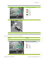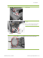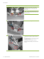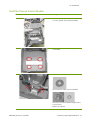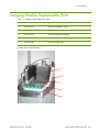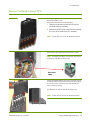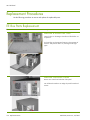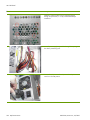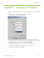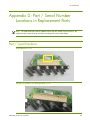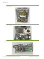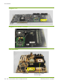
1
HP mPrinter 4000 Fixed Imager
Maintenance and Service Guide
HP Confidential
This document has been released for use only by non-HP entities that have signed associated confidential disclosure agreements.
© Copyright 2000-2007 Hewlett-Packard Development Company, L.P.
The information contained herein is subject to change without notice. The only warranties for HP products and services are set forth in the express
warranty statements accompanying such products and services. Nothing herein should be construed as constituting an additional warranty. HP shall not
be liable for technical or editorial errors or omissions contained herein.
Printed in the US
Reference number: 8007304e
Revision A: 02/2007
Legal notices
Disclaimers
HP makes no warranty regarding the accuracy or completeness of this material as it pertains to determination of the interaction of the
HP mPrinter 4000 Fixed Imager with the OEM's broader printing system. The OEM's printing system contains parameters which affect performance
but are not within HP's control. HP has not tested the HP mPrinter 4000 Fixed Imager in all configurations which may be attempted by the OEM
partners. It is the responsibility of the OEM partner to qualify it's printing system after incorporation of the HP mPrinter 4000 Fixed Imager.
Open Source Software Disclaimer
The Open Source Software included in the HP mPrinter 4000 Fixed Imager is composed of individual software components, each of which has its
own copyright and its own applicable license conditions. The OEM must review the licenses within the individual packages to understand your rights
under them. The licenses can be found in the folder called “licenses” on the CD provided to you by HP with every firmware release. All of the open
source software source code can be found on the same CD under the folder “source”.
Copyrights to the Open Source Software are held by the copyright holders.
Open Source Acknowledgements
This product includes software developed by the parties as described in the license files in the “licenses” folder on the provided CD.
The source code, object code, and documentation in the com.oreilly.servlet package is licensed by Hunter Digital Ventures, LLC.
Note to OEM Partner:
In order to be compliant with these open source software licenses, as documented in the OEM Sales Agreement, the OEM must:
•
Provide the open source software disclaimers and acknowledgements to the end users of the OEM’s product via their own documentation
•
Provide the open source software licenses to their end users
•
Provide a written offer to their end users to obtain a machine readable copy of the open source software source code in order to be in
compliance with the GNU General Public license or bundle it with every product and firmware upgrade binary.
Revision History
Table 1-1 Revision History
Date
Edition
Revision
(DA / Owner)
February 2007
A
Initial release of document per [75493W-ECO]
(EB / GL)
Contents
Revision History . . . . . . . . . . . . . . . . . . . . . . . . . . . . . . . . . . . . . . . . . . . . . . . . . . . . . . . . . . . . . . . . . . . . . 2
1 - Introduction. . . . . . . . . . . . . . . . . . . . . . . . . . . . . . . . . . . . . . . . . . . . . . . . . . . .7
Basic Assumptions . . . . . . . . . . . . . . . . . . . . . . . . . . . . . . . . . . . . . . . . . . . . . . . . . . . . . . . . . . . . . . . . .
About This Document . . . . . . . . . . . . . . . . . . . . . . . . . . . . . . . . . . . . . . . . . . . . . . . . . . . . . . . . . . . . . . .
Document Formatting Conventions . . . . . . . . . . . . . . . . . . . . . . . . . . . . . . . . . . . . . . . . . . . . . . . . . . . . . .
Related Documents . . . . . . . . . . . . . . . . . . . . . . . . . . . . . . . . . . . . . . . . . . . . . . . . . . . . . . . . . . . . . . . . .
Software . . . . . . . . . . . . . . . . . . . . . . . . . . . . . . . . . . . . . . . . . . . . . . . . . . . . . . . . . . . . . . . . . . . . . . . .
Hardware . . . . . . . . . . . . . . . . . . . . . . . . . . . . . . . . . . . . . . . . . . . . . . . . . . . . . . . . . . . . . . . . . . . . . . .
Consumables. . . . . . . . . . . . . . . . . . . . . . . . . . . . . . . . . . . . . . . . . . . . . . . . . . . . . . . . . . . . . . . . . . . . .
Replacement Parts . . . . . . . . . . . . . . . . . . . . . . . . . . . . . . . . . . . . . . . . . . . . . . . . . . . . . . . . . . . . . . . . .
Product Models and Replacement Parts Table. . . . . . . . . . . . . . . . . . . . . . . . . . . . . . . . . . . . . . . . . . . .
Service/Maintenance Disposables Not Provided . . . . . . . . . . . . . . . . . . . . . . . . . . . . . . . . . . . . . . . . . . . .
.. 7
.. 8
.. 8
.. 8
.. 8
.. 8
.. 9
.. 9
.. 9
. 11
2 - Safety. . . . . . . . . . . . . . . . . . . . . . . . . . . . . . . . . . . . . . . . . . . . . . . . . . . . . . . 13
Hazards . . . . . . . . . . . . .
MSDS . . . . . . . . . . . .
Personal Safety. . . . . .
Waste Management . .
....
....
....
....
....
....
....
....
...
...
...
...
....
....
....
....
....
....
....
....
...
...
...
...
....
....
....
....
...
...
...
...
....
....
....
....
....
....
....
....
...
...
...
...
....
....
....
....
.......
.......
.......
.......
...
...
...
...
.
.
.
.
.
.
.
.
.
.
.
.
.
.
.
.
.
.
.
.
.
.
.
.
13
14
14
15
3 - Precautions . . . . . . . . . . . . . . . . . . . . . . . . . . . . . . . . . . . . . . . . . . . . . . . . . . .17
Pinch Points . . . . . . . . . . . . . . . . . . . . . .
Imaging Head and Media Transport . .
Bottom Plate of the Imaging Head. . . .
Supplies . . . . . . . . . . . . . . . . . . . . . . . .
Frequency . . . . . . . . . . . . . . . . . . . . . . .
Flex Circuit Cleaning Procedure . . . . . . . .
....
....
....
....
....
....
....
....
....
....
....
....
...
...
...
...
...
...
....
....
....
....
....
....
...
...
...
...
...
...
....
....
....
....
....
....
....
....
....
....
....
....
...
...
...
...
...
...
....
....
....
....
....
....
.............
.............
.............
.............
.............
.............
.
.
.
.
.
.
.
.
.
.
.
.
.
.
.
.
.
.
17
18
18
19
19
20
4 - Troubleshooting/Service & Repair . . . . . . . . . . . . . . . . . . . . . . . . . . . . . . . . . . .21
Introduction . . . . . . . . . . . . . . . . . . . . . . . . . . . . . . . . . . . . .
General . . . . . . . . . . . . . . . . . . . . . . . . . . . . . . . . . . . . . . .
Equipment . . . . . . . . . . . . . . . . . . . . . . . . . . . . . . . . . . .
Repair Cautions . . . . . . . . . . . . . . . . . . . . . . . . . . . . . . .
LEDs . . . . . . . . . . . . . . . . . . . . . . . . . . . . . . . . . . . . . . . . . .
HP mPrinter 4000 Imaging Module. . . . . . . . . . . . . . . . . .
HP mPrinter 4000 Imager Controller . . . . . . . . . . . . . . . . .
HP mPrinter 4000 Ink Delivery System. . . . . . . . . . . . . . . .
Internal LEDs (mounted on PCAs) Reference Designators . . . . . .
HP mPrinter 4000 Imager Controller . . . . . . . . . . . . . . . . .
...
...
...
...
...
...
...
...
...
...
....
....
....
....
....
....
....
....
....
....
....
....
....
....
....
....
....
....
....
....
...
...
...
...
...
...
...
...
...
...
...................
...................
...................
...................
...................
...................
...................
...................
...................
...................
.
.
.
.
.
.
.
.
.
.
21
21
21
22
22
22
22
23
23
23
HP mPrinter 4000 Ink Delivery System. . . . .
OEM Interface and Error Codes. . . . . . . . . . . .
Normal Operation Sound and Visual Signals . .
Troubleshooting Guide . . . . . . . . . . . . . . . . . .
Imager Test Center . . . . . . . . . . . . . . . . . .
Warranty Incident Report. . . . . . . . . . . . . .
.................................
.................................
.................................
.................................
.................................
.................................
.
.
.
.
.
.
23
24
24
24
24
24
Engine PCA . . . . . . . . . . . . . . . . . . . . . . . . . . . . . . . . . . . . . . . . . . . . . . . . . . . . . . . . . 23
Interconnect PCA . . . . . . . . . . . . . . . . . . . . . . . . . . . . . . . . . . . . . . . . . . . . . . . . . . . . . 23
....
....
....
....
....
....
...
...
...
...
...
...
....
....
....
....
....
....
Service Event Documentation & Service Event Report . . . . . . . . . . . . . . . . . . . . . . . . . . . . . . . 27
Troubleshooting Flowcharts . . . . . . . . . . . . . . . . . . . . . . . . . . . . . . . . . . . . . . . . . . . . . . . . . . . . . . . . . . . . 28
Normal Start Up . . . . . . . . . . . . . . . . . . . . . . . . . . . . . . . . . . . . . . . . . . . . . . . . . . . . . . . . . . . . . . . . . 28
Troubleshooting Hierarchy . . . . . . . . . . . . . . . . . . . . . . . . . . . . . . . . . . . . . . . . . . . . . . . . .
E-Buzzer Detected Faults . . . . . . . . . . . . . . . . . . . . . . . . . . . . . . . . . . . . . . . . . . . . . . . . . . .
Non Operation Steps . . . . . . . . . . . . . . . . . . . . . . . . . . . . . . . . . . . . . . . . . . . . . . . . . . . . .
Imager Diagnostic Test . . . . . . . . . . . . . . . . . . . . . . . . . . . . . . . . . . . . . . . . . . . . . . . . . . . .
Controller Diagnostic Test . . . . . . . . . . . . . . . . . . . . . . . . . . . . . . . . . . . . . . . . . . . . . . . . . .
Service Station Diagnostic Test . . . . . . . . . . . . . . . . . . . . . . . . . . . . . . . . . . . . . . . . . . . . . .
IDS Diagnostic Test . . . . . . . . . . . . . . . . . . . . . . . . . . . . . . . . . . . . . . . . . . . . . . . . . . . . . .
Noise and Miscellaneous Items . . . . . . . . . . . . . . . . . . . . . . . . . . . . . . . . . . . . . . . . . . . . . .
29
30
31
32
33
34
35
36
LEDs & Recovery Actions . . . . . . . . . . . . . . . . . . . . . . . . . . . . . . . . . . . . . . . . . . . . . . . . . . . . . . . . . . . 37
8007304e, Revision A, 02/2007
1
HP Confidential
Print Quality / Operation Troubleshooting . . . . . . . . . . . . . . . . . . . . . . . . . . . . . . . . . . . . . . . . . . . . . . . . . . 38
Imager Test Center User’s Guide . . . . . . . . . . . . . . . . . . . . . . . . . . . . . . . . . . . . . . . . . . . . . . . . . . . . . . . . 40
Startup. . . . . . . . . . . . . . . . . . . . . . . . . . . . . . . . . . . . . . . . . . . . . . . . . . . . . . . . . . . . . . . . . . . . . . . . 41
Connecting the Controller . . . . . . . . . . . . . . . . . . . . . . . . . . . . . . . . . . . . . . . . . . . . . . .
Diagnostic Mode . . . . . . . . . . . . . . . . . . . . . . . . . . . . . . . . . . . . . . . . . . . . . . . . . . . . .
System Diagnostics. . . . . . . . . . . . . . . . . . . . . . . . . . . . . . . . . . . . . . . . . . . . . . . . . .
Shutdown Imager . . . . . . . . . . . . . . . . . . . . . . . . . . . . . . . . . . . . . . . . . . . . . . . . . . . . .
Exit . . . . . . . . . . . . . . . . . . . . . . . . . . . . . . . . . . . . . . . . . . . . . . . . . . . . . . . . . . . . . . .
Imager Test Center GUIs . . . . . . . . . . . . . . . . . . . . . . . . . . . . . . . . . . . . . . . . . . . . . . . .
41
42
42
43
43
43
OEM Commands . . . . . . . . . . . . . . . . . . . . . . . . . . . . . . . . . . . . . . . . . . . . . . . . . . . . . . . . . . . . . . . . 44
GET_SW_VERSION . . . . . . . . . . . . . . . . . . . . . . . . . . . . . . . . . . . . . . . . . . . . . . . . . . . 44
GET_SYSTEM_STATUS . . . . . . . . . . . . . . . . . . . . . . . . . . . . . . . . . . . . . . . . . . . . . . . . . 44
GET_PARAMETER . . . . . . . . . . . . . . . . . . . . . . . . . . . . . . . . . . . . . . . . . . . . . . . . . . . . . 45
FW Commands. . . . . . . . . . . . . . . . . . . . . . . . . . . . . . . . . . . . . . . . . . . . . . . . . . . . . . . . . . . . . . . . . . 51
Error Manager . . . . . . . . . . . . . . . . . . . . . . . . . . . . . . . . . . . . . . . . . . . . . . . . . . . . . . . 51
Diagnostic System. . . . . . . . . . . . . . . . . . . . . . . . . . . . . . . . . . . . . . . . . . . . . . . . . . . . . 53
Shutdown Manager . . . . . . . . . . . . . . . . . . . . . . . . . . . . . . . . . . . . . . . . . . . . . . . . . . . 59
Print Image . . . . . . . . . . . . . . . . . . . . . . . . . . . . . . . . . . . . . . . . . . . . . . . . . . . . . . . . . . . . . . . . . . . . . 60
Troubleshooting . . . . . . . . . . . . . . . . . . . . . . . . . . . . . . . . . . . . . . . . . . . . . . . . . . . . . . . . . . . . . . . . . 61
SVS Interface . . . . . . . . . . . . . . . . . . . . . . . . . . . . . . . . . . . . . . . . . . . . . . . . . . . . . . . . 61
Calibration Constant . . . . . . . . . . . . . . . . . . . . . . . . . . . . . . . . . . . . . . . . . . . . . . . . 61
IDS Interface . . . . . . . . . . . . . . . . . . . . . . . . . . . . . . . . . . . . . . . . . . . . . . . . . . . . . . . . 62
Tools and Help . . . . . . . . . . . . . . . . . . . . . . . . . . . . . . . . . . . . . . . . . . . . . . . . . . . . . . . . . . . . . . . . . . 63
Tools . . . . . . . . . . . . . . . . . . . . . . . . . . . . . . . . . . . . . . . . . . . . . . . . . . . . . . . . . . . . . . 63
Help . . . . . . . . . . . . . . . . . . . . . . . . . . . . . . . . . . . . . . . . . . . . . . . . . . . . . . . . . . . . . . 63
5 - Repair Validation . . . . . . . . . . . . . . . . . . . . . . . . . . . . . . . . . . . . . . . . . . . . . . 65
Engine PCA . . . . . . . . . . . . . . . . . . . . . . . . . . . . . . . . . . . . . . . . . . . . . . . . . . . . . . . . .
Interconnect PCA . . . . . . . . . . . . . . . . . . . . . . . . . . . . . . . . . . . . . . . . . . . . . . . . . . . . .
IDS PCA . . . . . . . . . . . . . . . . . . . . . . . . . . . . . . . . . . . . . . . . . . . . . . . . . . . . . . . . . . .
Service Station PCA . . . . . . . . . . . . . . . . . . . . . . . . . . . . . . . . . . . . . . . . . . . . . . . . . . .
Carriage-Backplane PCA . . . . . . . . . . . . . . . . . . . . . . . . . . . . . . . . . . . . . . . . . . . . . . . .
Imager Controller . . . . . . . . . . . . . . . . . . . . . . . . . . . . . . . . . . . . . . . . . . . . . . . . . . . . .
IDS . . . . . . . . . . . . . . . . . . . . . . . . . . . . . . . . . . . . . . . . . . . . . . . . . . . . . . . . . . . . . . .
Service Station . . . . . . . . . . . . . . . . . . . . . . . . . . . . . . . . . . . . . . . . . . . . . . . . . . . . . . .
Imaging Module . . . . . . . . . . . . . . . . . . . . . . . . . . . . . . . . . . . . . . . . . . . . . . . . . . . . . .
Imaging Head (Imaging Module and Service Station) . . . . . . . . . . . . . . . . . . . . . . . . . . . .
Entire Imager System . . . . . . . . . . . . . . . . . . . . . . . . . . . . . . . . . . . . . . . . . . . . . . . . . . .
Printhead . . . . . . . . . . . . . . . . . . . . . . . . . . . . . . . . . . . . . . . . . . . . . . . . . . . . . . . . . . .
Ink Cartridges . . . . . . . . . . . . . . . . . . . . . . . . . . . . . . . . . . . . . . . . . . . . . . . . . . . . . . .
66
69
70
72
76
79
82
85
86
87
93
96
97
6 - Replacement Parts. . . . . . . . . . . . . . . . . . . . . . . . . . . . . . . . . . . . . . . . . . . . . . 99
General Safety Information . . . . . . . . . . . . . . . . . . . . . . . . . . . . . . . . . . . . . . . . . . . . . . . . . . . . .
Handling HP Supplies . . . . . . . . . . . . . . . . . . . . . . . . . . . . . . . . . . . . . . . . . . . . . . . . . . . . . . . . .
HP Supply Storage . . . . . . . . . . . . . . . . . . . . . . . . . . . . . . . . . . . . . . . . . . . . . . . . . . . . . . . .
Removal and Storage of HP Supplies . . . . . . . . . . . . . . . . . . . . . . . . . . . . . . . . . . . . . . . . . . . .
Removal and Storage of Printheads . . . . . . . . . . . . . . . . . . . . . . . . . . . . . . . . . . . . . . . . . . . . .
To Remove a Printhead . . . . . . . . . . . . . . . . . . . . . . . . . . . . . . . . . . . . . . . . . . . . . . . . . . . . .
Ink Delivery System Replaceable Parts . . . . . . . . . . . . . . . . . . . . . . . . . . . . . . . . . . . . . . . . . . . . . .
Replacement Procedures . . . . . . . . . . . . . . . . . . . . . . . . . . . . . . . . . . . . . . . . . . . . . . . . . . . .
Remove the IDS from the Box . . . . . . . . . . . . . . . . . . . . . . . . . . . . . . . . . .
Remove the Cover. . . . . . . . . . . . . . . . . . . . . . . . . . . . . . . . . . . . . . . . . .
Replace the Cover . . . . . . . . . . . . . . . . . . . . . . . . . . . . . . . . . . . . . . . . .
Remove the PILS PCA . . . . . . . . . . . . . . . . . . . . . . . . . . . . . . . . . . . . . . .
Replace the PILS PCA . . . . . . . . . . . . . . . . . . . . . . . . . . . . . . . . . . . . . . .
Remove the Pressure Control Module. . . . . . . . . . . . . . . . . . . . . . . . . . . . .
Install the Pressure Control Module . . . . . . . . . . . . . . . . . . . . . . . . . . . . . .
Remove Ink Stall Assembly . . . . . . . . . . . . . . . . . . . . . . . . . . . . . . . . . . . .
2
..
..
..
..
..
..
..
..
..
..
..
..
..
..
..
..
.
.
.
.
.
.
.
.
.
.
.
.
.
.
.
.
..
..
..
..
..
..
..
..
....
....
....
....
....
....
....
....
..
..
..
..
..
..
..
..
.
.
.
.
.
.
.
.
. . 99
. . 99
. . 99
. . 99
. . 99
. 100
. 101
. 101
102
103
104
105
106
107
111
114
8007304e, Revision A, 02/2007
HP Confidential
Install the Ink Stall Assembly . . . . . . . . . . . . . . . . . . . . . . . . . . . . . . . . . . . . . . . . . . . . .
Removal of Ink Tube Assembly and Crane . . . . . . . . . . . . . . . . . . . . . . . . . . . . . . . . . . .
Install Ink Tube Assembly and/or Crane . . . . . . . . . . . . . . . . . . . . . . . . . . . . . . . . . . . .
Repackage the IDS . . . . . . . . . . . . . . . . . . . . . . . . . . . . . . . . . . . . . . . . . . . . . . . . . . .
120
125
127
128
Remove the Imaging Module from the Box . . . . . . . . . . . . . . . . . . . . . . . . . . . . . . . . . . .
Remove Servo PCA . . . . . . . . . . . . . . . . . . . . . . . . . . . . . . . . . . . . . . . . . . . . . . . . . . .
Install Servo PCA . . . . . . . . . . . . . . . . . . . . . . . . . . . . . . . . . . . . . . . . . . . . . . . . . . . .
Remove Service Station . . . . . . . . . . . . . . . . . . . . . . . . . . . . . . . . . . . . . . . . . . . . . . . .
Install Service Station. . . . . . . . . . . . . . . . . . . . . . . . . . . . . . . . . . . . . . . . . . . . . . . . . .
Remove Printhead Connect PCA . . . . . . . . . . . . . . . . . . . . . . . . . . . . . . . . . . . . . . . . . .
Install Printhead Connect PCA . . . . . . . . . . . . . . . . . . . . . . . . . . . . . . . . . . . . . . . . . . .
Replace Carriage PCA . . . . . . . . . . . . . . . . . . . . . . . . . . . . . . . . . . . . . . . . . . . . . . . .
Remove Printhead Latch Assembly. . . . . . . . . . . . . . . . . . . . . . . . . . . . . . . . . . . . . . . . .
Install Printhead Latch Assembly . . . . . . . . . . . . . . . . . . . . . . . . . . . . . . . . . . . . . . . . . .
130
132
135
138
140
141
143
146
148
150
Remove & Install Fan Filter . . . . . . . . . . . . . . . . . . . . . . . . . . . . . . . . . . . . . . . . . . . . . .
Remove Controller Cover . . . . . . . . . . . . . . . . . . . . . . . . . . . . . . . . . . . . . . . . . . . . . . .
Install Controller Cover . . . . . . . . . . . . . . . . . . . . . . . . . . . . . . . . . . . . . . . . . . . . . . . .
Remove Rear Fan . . . . . . . . . . . . . . . . . . . . . . . . . . . . . . . . . . . . . . . . . . . . . . . . . . . .
Install Rear Fan . . . . . . . . . . . . . . . . . . . . . . . . . . . . . . . . . . . . . . . . . . . . . . . . . . . . . .
Remove Microprocessor Fan. . . . . . . . . . . . . . . . . . . . . . . . . . . . . . . . . . . . . . . . . . . . .
Install Microprocessor Fan . . . . . . . . . . . . . . . . . . . . . . . . . . . . . . . . . . . . . . . . . . . . . .
Remove Front Fan . . . . . . . . . . . . . . . . . . . . . . . . . . . . . . . . . . . . . . . . . . . . . . . . . . . .
Install Front Fan . . . . . . . . . . . . . . . . . . . . . . . . . . . . . . . . . . . . . . . . . . . . . . . . . . . . .
Remove Microprocessor (CPU) . . . . . . . . . . . . . . . . . . . . . . . . . . . . . . . . . . . . . . . . . . .
Install Microprocessor (CPU). . . . . . . . . . . . . . . . . . . . . . . . . . . . . . . . . . . . . . . . . . . . .
Remove Engine PCA . . . . . . . . . . . . . . . . . . . . . . . . . . . . . . . . . . . . . . . . . . . . . . . . . .
Install Engine PCA. . . . . . . . . . . . . . . . . . . . . . . . . . . . . . . . . . . . . . . . . . . . . . . . . . . .
Remove Memory, RAM, 256 MB . . . . . . . . . . . . . . . . . . . . . . . . . . . . . . . . . . . . . . . . .
Install Memory, RAM, 256 MB . . . . . . . . . . . . . . . . . . . . . . . . . . . . . . . . . . . . . . . . . . .
Remove Formatter PCA . . . . . . . . . . . . . . . . . . . . . . . . . . . . . . . . . . . . . . . . . . . . . . . .
Install Formatter PCA . . . . . . . . . . . . . . . . . . . . . . . . . . . . . . . . . . . . . . . . . . . . . . . . . .
Remove Hard Disk Drive . . . . . . . . . . . . . . . . . . . . . . . . . . . . . . . . . . . . . . . . . . . . . . .
Install Hard Disk Drive . . . . . . . . . . . . . . . . . . . . . . . . . . . . . . . . . . . . . . . . . . . . . . . . .
Remove Aux PSU AC - DC, 24V Power Supply . . . . . . . . . . . . . . . . . . . . . . . . . . . . . . . .
Install Aux PSU AC - DC, 24V Power Supply . . . . . . . . . . . . . . . . . . . . . . . . . . . . . . . . .
Remove ATX Power Supply Unit . . . . . . . . . . . . . . . . . . . . . . . . . . . . . . . . . . . . . . . . . .
Install ATX Power Supply Unit . . . . . . . . . . . . . . . . . . . . . . . . . . . . . . . . . . . . . . . . . . . .
Replace Network Card . . . . . . . . . . . . . . . . . . . . . . . . . . . . . . . . . . . . . . . . . . . . . . . .
Replace LEDs . . . . . . . . . . . . . . . . . . . . . . . . . . . . . . . . . . . . . . . . . . . . . . . . . . . . . . .
156
156
157
157
157
158
159
161
163
165
167
168
169
170
170
171
172
172
173
174
177
180
181
183
183
Imaging Module Replaceable Parts . . . . . . . . . . . . . . . . . . . . . . . . . . . . . . . . . . . . . . . . . . . . . . . . . . . . . 129
Replacement Procedures . . . . . . . . . . . . . . . . . . . . . . . . . . . . . . . . . . . . . . . . . . . . . . . . . . . . . . . . . . 130
Imager Controller Replaceable Parts . . . . . . . . . . . . . . . . . . . . . . . . . . . . . . . . . . . . . . . . . . . . . . . . . . . . . 153
Replacement Procedures . . . . . . . . . . . . . . . . . . . . . . . . . . . . . . . . . . . . . . . . . . . . . . . . . . . . . . . . . . . . . 156
EE Box Parts Replacement . . . . . . . . . . . . . . . . . . . . . . . . . . . . . . . . . . . . . . . . . . . . . . . . . . . . . . . . . 156
A - RoHS vs. Non-RoHS Part Numbers. . . . . . . . . . . . . . . . . . . . . . . . . . . . . . . . . .185
B - Transporting Components . . . . . . . . . . . . . . . . . . . . . . . . . . . . . . . . . . . . . . . .187
Move Across a Room . . . . . . . . . . . . . . . . . . . . . . . . . . . . . . . . . . . . . . . . . . . . . . . . . . . . . . . . . . . . . . . 187
Move to New Installation . . . . . . . . . . . . . . . . . . . . . . . . . . . . . . . . . . . . . . . . . . . . . . . . . . . . . . . . . . . . 188
C - Changing an IP Address. . . . . . . . . . . . . . . . . . . . . . . . . . . . . . . . . . . . . . . . .189
D - Part / Serial Number Locations in Replacement Parts . . . . . . . . . . . . . . . . . . . . .191
Part / Serial Numbers . . . . . . . . . . . . . . . . . . . . . . . . . . . . . . . . . . . . . . . . . . . . . . . . . . . . . . . . . . . . 191
Backplane PCA . . . . . . . . . . . . . . . . . . . . . . . . . . . . . . . . . . . . . . . . . . . . . . . . . . . . . 191
Serial Number for Backplane PCA . . . . . . . . . . . . . . . . . . . . . . . . . . . . . . . . . . . . . . . . 191
8007304e, Revision A, 02/2007
3
HP Confidential
Carriage PCA . . . . . . . . . . . . . . . . . . . . . . . . . . . . . . . . . . . . . . . . . . . . . . . . . . . . . .
Carriage PCA Serial Number. . . . . . . . . . . . . . . . . . . . . . . . . . . . . . . . . . . . . . . . . . . .
Servo PCA . . . . . . . . . . . . . . . . . . . . . . . . . . . . . . . . . . . . . . . . . . . . . . . . . . . . . . . . .
Servo PCA Serial Number . . . . . . . . . . . . . . . . . . . . . . . . . . . . . . . . . . . . . . . . . . . . . .
Interconnect PCA . . . . . . . . . . . . . . . . . . . . . . . . . . . . . . . . . . . . . . . . . . . . . . . . . . . .
Interconnect PCA Serial Number. . . . . . . . . . . . . . . . . . . . . . . . . . . . . . . . . . . . . . . . . .
Engine PCA . . . . . . . . . . . . . . . . . . . . . . . . . . . . . . . . . . . . . . . . . . . . . . . . . . . . . . . .
Engine PCA Serial Number . . . . . . . . . . . . . . . . . . . . . . . . . . . . . . . . . . . . . . . . . . . . .
Motherboard . . . . . . . . . . . . . . . . . . . . . . . . . . . . . . . . . . . . . . . . . . . . . . . . . . . . . . .
Motherboard Part Number. . . . . . . . . . . . . . . . . . . . . . . . . . . . . . . . . . . . . . . . . . . . . .
Motherboard Serial Number . . . . . . . . . . . . . . . . . . . . . . . . . . . . . . . . . . . . . . . . . . . .
Hard Drive. . . . . . . . . . . . . . . . . . . . . . . . . . . . . . . . . . . . . . . . . . . . . . . . . . . . . . . . .
Hard Drive Serial Number . . . . . . . . . . . . . . . . . . . . . . . . . . . . . . . . . . . . . . . . . . . . . .
Hard Drive Serial Number . . . . . . . . . . . . . . . . . . . . . . . . . . . . . . . . . . . . . . . . . . . . . .
24 V Power Supply . . . . . . . . . . . . . . . . . . . . . . . . . . . . . . . . . . . . . . . . . . . . . . . . . . .
24 V Power Supply Serial Number . . . . . . . . . . . . . . . . . . . . . . . . . . . . . . . . . . . . . . . .
ATX Power Supply . . . . . . . . . . . . . . . . . . . . . . . . . . . . . . . . . . . . . . . . . . . . . . . . . . .
ATX Power Supply Serial Number. . . . . . . . . . . . . . . . . . . . . . . . . . . . . . . . . . . . . . . . .
192
192
192
193
193
193
194
194
194
195
195
195
196
196
196
197
197
197
E - Service and Repair Tools . . . . . . . . . . . . . . . . . . . . . . . . . . . . . . . . . . . . . . . . 199
Imager Tools. . . . . . . . . . . . . . . . . . . . . . . . . . . . . . . . . . . . . . . . . . . . . . . . . . . . . . . . . . . . . . . . . . . 199
EE Box Tools. . . . . . . . . . . . . . . . . . . . . . . . . . . . . . . . . . . . . . . . . . . . . . . . . . . . . . . . . . . . . . . . . . . 199
IDS Tools . . . . . . . . . . . . . . . . . . . . . . . . . . . . . . . . . . . . . . . . . . . . . . . . . . . . . . . . . . . . . . . . . . . . . 200
F - Fastener Seating Torque. . . . . . . . . . . . . . . . . . . . . . . . . . . . . . . . . . . . . . . . . 201
Fastener Driver Calibration. . . . . . . . . . . . . . . . . . . . . . . . . . . . . . . . . . . . . . . . . . . . . . . . . . . . . . . . . 201
Purpose . . . . . . . . . . . . . . . . . . . . . . . . . . . . . . . . .
Equipment . . . . . . . . . . . . . . . . . . . . . . . . . . . . . . .
Power Drivers Procedure . . . . . . . . . . . . . . . . . . . . .
Mechanical torque screwdrivers or torque watches . . .
Torque Analyzer Calibration . . . . . . . . . . . . . . . . . .
Fastener Nominal Torque Table . . . . . . . . . . . . . . . . . . .
..
..
..
..
..
..
.
.
.
.
.
.
..
..
..
..
..
..
..
..
..
..
..
..
.
.
.
.
.
.
..
..
..
..
..
..
..
..
..
..
..
..
.
.
.
.
.
.
..
..
..
..
..
..
.
.
.
.
.
.
..
..
..
..
..
..
..
..
..
..
..
..
.
.
.
.
.
.
..
..
..
..
..
..
..
..
..
..
..
..
.
.
.
.
.
.
201
201
201
202
202
203
G - Repair and Fail Codes . . . . . . . . . . . . . . . . . . . . . . . . . . . . . . . . . . . . . . . . . 205
Type Code. . . . . . . . . . . . . . . . . . . . . . . . . . . . . . . . . . . . . . . . . . . . . . . . .
Primary and Secondary Codes . . . . . . . . . . . . . . . . . . . . . . . . . . . . . . . . . . .
Last Two Digits . . . . . . . . . . . . . . . . . . . . . . . . . . . . . . . . . . . . . . . . . . . . . .
Component Identifier for the Primary/Secondary Codes . . . . . . . . . . . . . . . . .
Reason Codes . . . . . . . . . . . . . . . . . . . . . . . . . . . . . . . . . . . . . . . . . . . . . .
..
..
..
..
..
.
.
.
.
.
..
..
..
..
..
..
..
..
..
..
.
.
.
.
.
205
205
206
206
207
H - RS-232 Port and OEM Troubleshooting and Maintenance . . . . . . . . . . . . . . . . . 209
About the RS-232 Serial Interface . . . . . . . . . . . . . . . . . . . . . . . . . . . . . . . . . . . . . . . . . . . . . . . . . . . . 209
Troubleshooting . . . . . . . . . . . . . . . . . . . . . . . . . . . . . . . . . . . . . . . . . . . . . . . . . . . . . . . . . . . . . . . . 209
OEM Commands Typically Used in Troubleshooting . . . . . . . . . . . . . . . . . . . . . . . . . . . . . . . . . . . . . . . 211
Control Interface . . . . . . . . . . . . . . . . . . . . . . . . . . . . . . . . . . . . . . . . . . . . . . . . . . . . . 211
Status Interface . . . . . . . . . . . . . . . . . . . . . . . . . . . . . . . . . . . . . . . . . . . . . . . . . . . . . . 212
Maintenance Instructions . . . . . . . . . . . . . . . . . . . . . . . . . . . . . . . . . . . . . . . . . . . . . . . 212
I - Firmware Update Procedure . . . . . . . . . . . . . . . . . . . . . . . . . . . . . . . . . . . . . . 215
Equipment . . . . . . . . . . . . . . . . . . . . . . . . . . . . . . . . . . . . . . . . . . . . . . . . . . . . . . . . . . . . . . . . . . . . 215
Procedure. . . . . . . . . . . . . . . . . . . . . . . . . . . . . . . . . . . . . . . . . . . . . . . . . . . . . . . . . . . . . . . . . . . . . 215
J - Ink Removal / Purging Procedure. . . . . . . . . . . . . . . . . . . . . . . . . . . . . . . . . . . 219
Before you begin. . . . . . . . . . . . . . . . . . . . . . . . . . . . . . . . . . . . . . . . . . . . . . . . . . . . . . . . . . . . . . . . 219
Procedure. . . . . . . . . . . . . . . . . . . . . . . . . . . . . . . . . . . . . . . . . . . . . . . . . . . . . . . . . . . . . . . . . . . . . 219
K - Returning Modules with Ink Contamination. . . . . . . . . . . . . . . . . . . . . . . . . . . . 225
Goal . . . . . . . . . . . . . . . . . . . . . . . . . . . . . . . . . . . . . . . . . . . . . . . . . . . . . . . . . . . . . . . . . . . . . . . . 225
Precaution . . . . . . . . . . . . . . . . . . . . . . . . . . . . . . . . . . . . . . . . . . . . . . . . . . . . . . . . . . . . . . . . . . . . 225
4
8007304e, Revision A, 02/2007
HP Confidential
Procedure . . . . . . . . . . . . . . . . . . . . . . . . . . . . . . . . . . . . . . . . . . . . . . . . . . . . . . . . . . . . . . . . . . . . 225
8007304e, Revision A, 02/2007
5
HP Confidential
6
8007304e, Revision A, 02/2007
HP Confidential
1
Introduction
This document provides HP recommended maintenance and service procedures for the Q2337A,
HP mPrinter 4000 Fixed Imager. It will enable an OEM integrator to develop maintenance and service
procedures. Information included:
• Chapter 2, Safety, covers cautions and hazards including personal safety and waste management.
• Chapter 3, Precautions, covers periodic maintenance procedures and recommended frequency.
• Chapter 4, Troubleshooting/Service & Repair, covers recommended service and repair procedures, as
well as troubleshooting flowcharts.
• Chapter 5, Repair Validation, covers procedures to validate repairs performed on the imager and its
components.
• Chapter 6, Replacement Parts, covers details on replacement parts used in the HP mPrinter 4000, as
well as detailed procedures for installing those parts.
Several appendices are also included, covering topics such as return procedures, locating part or serial
numbers on replacement parts, fastener torque values, and error codes.
NOTE: This document is confidential and must be used in accordance with the Confidential Disclosure
Agreement (CDA) that is in place with HP.
All information presented in this document is presented AS IS, without any representation regarding its
accuracy or completeness. Any reliance on or use of information contained herein is undertaken at the
sole risk of the reader.
Basic Assumptions
This manual is written primarily for field technicians with the assumption that every technician is trained
and therefore familiar with the HP mPrinter 4000 and authorized by the OEM to perform the service. The
manual makes no attempt to explain how to remove any of the HP mPrinter 4000 modules from the
OEM's platform; this remains the responsibility of the OEM. Disassembly instructions begin with the
module already removed from the OEM's platform.
HP does not provide any small miscellaneous parts such as screws, washers, cable ties, or other small,
commercially available off-the-shelf items; the OEM is responsible to provide these items to their service
personnel. Service personnel must also be capable of repackaging replacement parts required to be
returned to HP for failure analysis, including boxing and securing of the parts that require return to HP in
the HP-approved box.
8007304e, Revision A, 02/2007
Basic Assumptions 7
HP Confidential
About This Document
If you are reading an electronic version of this document, there are internal links that will take you to
referenced topics. For example, clicking on an item listed in the table of contents will take you to that
page.
NOTE: Illustrations with a number in a circle are cross-referenced to the corresponding step in the
procedure. For example, 3 illustrates step 3 of the related procedure.
Document Formatting Conventions
Command
ImagerMaintenance command
State
intervention state
Interrupt
paper jam
Mode
Access Mode
Instruction
ENTER or EXIT instructions
ASCII strings, or user input
CAPITAL LETTERS (courier)
Related Documents
Integration Guide (802896ce)
Firmware and Software Integration Guide (80074a73)
Service Videos (Q2337-90013)
Product Brochure (802896cd)
Software
Imager Test Center for Windows
Imager Controller Programmed HD, Firmware Code
Hardware
This Manual covers the following product models which together make up the HP mPrinter 4000:
• Controllers: Q7473A and Q7473L
8
Introduction
8007304e, Revision A, 02/2007
HP Confidential
• Ink Delivery System: Q2326A and Q2326L
• Imaging Module (Imaging Head): Q2337A and Q2337L
• External Cable Set: Q7474A and CB882L
These modules are interchangeable; the main difference is that the “L” modules are compliant with the
European Restriction of Hazardous Substances Directive. The EU RoHS directive restricts the presence of
certain substances in electric and electrical products and their component parts offered for sale in the
European Union after July 1, 2006. The purpose of RoHS is to contribute to the protection of human health
and the environment. See product brochure for a complete list of environmental compliance approvals.
Only the controllers have minor internal differences in the mounting of the hard drives and in the main
power cable to the 24V power supply, but all other replacement parts are interchangeable.
Consumables
• Black 4240 Pigment Printhead HP Part Number: Q2389L
• HP Black 4240 Pigment 775 ml Ink Cartridge HP Part Number: Q2326-60011
• Printhead Cleaner HP Part Number Q2326-60011
• Setup Pens HP Part Number C8863L
See product brochure for a current, complete list of approved supplies.
Replacement Parts
The Replacement Parts list is below, representing the parts authorized for replacement under warranty by
certified service technicians. No lower level parts may be change due to the manufacturing procedures
and/or tools required for proper installation and validation. Disassembly of modules or assemblies to an
unauthorized level by any service technician will immediately void the warranty.
Product Models and Replacement Parts Table
Table 1-1
Product Models and Replacement Parts Tables
Imager Controller
Part Number
Used in non-ROHS/ROHS Parts
PCA, Engine, FFI
Q2327-67001
Q7473A & Q7473L
PCA, Interconnect, FFI
Q2327-67002
Q7473A & Q7473L
PCA, Formatter, Jesulin
Q2327-67006
Q7473A & Q7473L
Celeron CPU
Q2326-67008
Q7473A & Q7473L
Fan Assembly 15VDC 31cfm
Q2337-67022
Q7473A & Q7473L
Memory, RAM, cmos, 256MB
Q2326-67009
Q7473A & Q7473L
8007304e, Revision A, 02/2007
Consumables 9
HP Confidential
Table 1-1
Product Models and Replacement Parts Tables
Imager Controller
Part Number
Used in non-ROHS/ROHS Parts
FanFilter_2494 (Bag of 10)
Q2337-67001
Q7473A & Q7473L
Fan_CR0824UB_A71GL
Q2337-67002
Q7473A & Q7473L
Hard Disk Drive (40 Gb, IDE2)
Q2326-67010
Q7473A & Q7473L
ATX Power Supply Unit
Q2326-67012
Q7473A & Q7473L
Aux PSU AC-DC, 24V ROHS
Q2326-67013
Q7473A & Q7473L
Giga Bit Card (PWLA8391MTG1P20)
Q2337-67014
Q7473A & Q7473L
Cable, Power / Reset
Q2337-67003
Q7473A & Q7473L
Cable, INC to Rear Panel
Q2337-67004
Q7473A & Q7473L
Cable, Engine/ MB Control
Q2337-67007
Q7473A & Q7473L
Cable, DC Output to INTC
Q2337-67009
Q7473A & Q7473L
Cable, Engine to INTC
Q2337-67010
Q7473A & Q7473L
Cable, Fan to Power Supply
Q2337-67017
Q7473A & Q7473L
Imaging Module
Part Number
Used in non-ROHS/ROHS Parts
PCA, Carriage, FFI
Q2327-67003
Q2337A & Q2337L
Assy, PH Interconnect, FFI (set of 5)
Q2326-67001
Q2337A & Q2337L
Assy, Service Station [5x1]
Q2337-67011
Q2337A & Q2337L
PCA, Servo, FFI
Q2327-67004
Q2337A & Q2337L
PCA, Printhead Connect
Q2337-67019
Q2337A & Q2337L
Ink Delivery System
Part Number
Used in non-ROHS/ROHS Parts
PCA, IDS, FFI
Q2327-67005
Q2326A & Q2326L
PCA, need tube to be added to PCA
Assy, Ink Feed, Array [5x1]
Q2337-67020
Q2326A & Q2326L
Pressure Control Module
Q2326-67016
Q2326A & Q2326L
Assy, Stall, Large, Single
Q2326-67015
Q2326A & Q2326L
Cable RS-232
10
Q2326A & Q2326L
Introduction
Q2326A & Q2326L
8007304e, Revision A, 02/2007
HP Confidential
Ink Delivery System
Part Number
Cable stall connect
Used in non-ROHS/ROHS Parts
Q2326A & Q2326L
Assy, Tube Ink Flow
Q2326-67017
Q2337A & Q2337L
External Cable Set
Part Number
Used in non-ROHS/ROHS Parts
Assy, Cable Harness, IH Power
Q2326-67002
Q7473A & Q7473L
Assy, Cable Harness, IH Data
Q2326-67003
Q7473A & Q7473L
Assy, Cable Harness, Encoder
Q2326-67004
Q7473A & Q7473L
Assy, Cable Harness, Top of Form
Q2326-67005
Q7473A & Q7473L
Assy, Cable Harness, IDS
Q2326-67007
Q7473A & Q7473L
Assy, Cable Service Station
Q2326-67018
Q7473A & Q7473L
Cable Kit, 3m
Q7474A
Q7473A
Service/Maintenance Disposables Not Provided
• Large Rectangular Head Swab: This is general purpose closed cell polyurethane foam with a rigid
paddle used to clean the dimple contacts in the latch assembly. An example is ITW Texwipe® part
number TX707A
• Wipe Cloth: This is a tight weave cotton free of free floating fibers on the fabric surface. An example is
the ITW Texwipe® part number TX309
8007304e, Revision A, 02/2007
Service/Maintenance Disposables Not Provided 11
HP Confidential
This page intentionally left blank
12
Introduction
8007304e, Revision A, 02/2007
HP Confidential
2
Safety
Hazards
The safety hazards associated with the HP mPrinter 4000 Fixed Imager are described in the Hazard
Matrix table below. Gray-shaded rows indicate hazards that are not present.
Table 2-1
Hazard Matrix
Potential Hazard
Present
Chemical
Yes
Summary
Hazard: Ink
Prolonged inhalation of ink aerosol or vapors may cause irritation to
the respiratory tract.
• Ink may be a potential skin and eye irritant.
Injury Prevention:
•
•
•
•
Avoid prolonged or repeated exposure, inhalation, and contact with
skin and eyes.
Wear lab coat, safety glasses, and latex gloves.
Avoid direct contact with chemicals.
NOTE: See appropriate MSDS for more detailed health hazard data.
Hazard: Perchlorate
Attention California users:
The battery supplied with this product may contain perchlorate material.
Special handling may apply. See http://www.dtsc.ca.gov/
hazardouswaste/perchlorate for information.
Control Software
No
Hazard: <
>
Injury Prevention: <
Electrical
No
Hazard: <
>
Injury Prevention: <
Ergonomic
No
Hazard: <
No
Hazard: <
No
Hazard: <
>
>
Injury Prevention: <
8007304e, Revision A, 02/2007
>
>
Injury Prevention: <
Hydraulic
>
>
Injury Prevention: <
Gas
>
>
Hazards 13
HP Confidential
Table 2-1
Hazard Matrix
Potential Hazard
Present
Summary
Laser
No
Hazard: <
>
Injury Prevention: <
Mechanical
Yes
>
Hazard: pinch points present at the Q2337 Imaging Head:
•
•
Between the Imaging Head and media transport.
On the bottom plate of the Imaging Head.
Injury Prevention: keep fingers and clothing clear of pinch points.
Noise
No
Hazard: <
>
Injury Prevention: <
Pneumatic
No
Hazard: <
>
Injury Prevention: <
Radiation
No
Hazard: <
No
Hazard: <
No
Hazard: <
>
>
Injury Prevention: <
Ultrasonic
>
>
Injury Prevention: <
Temperature
>
>
>
Injury Prevention: <
>
MSDS
MSDS sheets may be obtained from the HP website located at www.hp.com.
Personal Safety
NOTE: Check local regulations; in some areas ink is considered hazardous waste.
Materials used for priming and recovery service must be disposed of according to local regulation.
Go to www.hp.com to obtain the MSDS Data Sheet.
Table 2-2
14
Personal Protective Equipment (PPE)
Condition or Activity
PPE
Print Cartridge Recovery Service
Lab Coat, Goggles, Latex Gloves
Safety
8007304e, Revision A, 02/2007
HP Confidential
Waste Management
CAUTION: Ink is considered hazardous waste according to some local regulations. Always check local
regulations before disposal. MSDS sheets may be obtained from the HP website located at www.hp.com.
CAUTION: Materials used for priming and recovery service must be disposed of according to local
regulation.
8007304e, Revision A, 02/2007
Hazards 15
HP Confidential
This page intentionally left blank
16
Safety
8007304e, Revision A, 02/2007
HP Confidential
3
Precautions
The HP mPrinter 4000 Fixed Imager is designed to be virtually maintenance free. However, due to the
nature of industrial environments some components in the Imager require a small amount of maintenance.
CAUTION: Do NOT clean the Imaging Module with compressed air if the
printheads are not in the capped position. This may spray ink onto areas of the
imaging head that must remain clean and free of ink.
Even in the capped position, cleaning with compressed air is not recommended.
Follow the Low Level Recovery Service procedures (see the HP mPrinter 4000 Fixed
Imager Integration Guide, 802896ce) to perform a gentle cleaning when needed.
CAUTION: Always power down before disconnecting any cables. Disconnecting
cables with the HP mPrinter 4000 powered will damage printed circuit board
electronics.
CAUTION:
Observe precautions for handling Electrostatic Sensitive Devices.
Pinch Points
Two potential pinch point risks have been identified for the Q2337 Imaging Head.
1. Between the Imaging Head and media transport.
2. Insertion of a finger into the holes on the bottom plate of the Imaging Head.
CAUTION:
The moving belt near the unit could injure fingers. Do NOT touch belt when operating.
CAUTION: The cleaning station may move unexpectedly and trap or injure fingers. Do NOT reach into
the unit when it is powered.
8007304e, Revision A, 02/2007
Pinch Points 17
HP Confidential
TIP: Remember: cleaning station refers to the printhead cleaner carriage, printhead cleaners, and all of
the components associated with the Service Station in the Imaging Module.
Imaging Head and Media Transport
CAUTION: The media transport is rigidly mounted under the Imaging Head which creates the possibility
of a pinch point between the Imaging Head and the media transport.
To mitigate this risk, use light curtains to disable the media transport.
A system that monitors media transport motor torque that will cut power on torque spikes, to minimize the
damage done in a pinch.
• A clutch on the media transport that disengages the drive if there is a pinch.
• Other sensors that will disable the media transport if a potential pinch occurs.
• Warning labels and operator training.
Bottom Plate of the Imaging Head
CAUTION: The printheads protrude through the holes in the bottom plate of the Imaging Head. If the
servicing module activates servicing while a finger is inserted into a hole, the service station could pinch a
finger against the bottom plate.
18
Precautions
8007304e, Revision A, 02/2007
HP Confidential
Supplies
Table 3-1
Recommended supplies
Recommended supplies
ITW Texwipes
de-ionized water
foam swabs
Frequency
NOTE: See the HP mPrinter 4000 Fixed Imager Integration Guide, 802896ce for all information on
maintenance of printheads.
Table 3-2
Maintenance schedule
Maintenance procedure
Inspect & clean flex circuit
each printhead
change
weekly or
as needed
every 6
months
X
Clean flex cables
X
Clean imaging head bottom
X
Inspect sliding/moving surfaces
X
Slide & lead screw operation
X
Inspect Imager Controller air filter
X
Run alignment plot
8007304e, Revision A, 02/2007
X
X
X
Supplies 19
HP Confidential
Flex Circuit Cleaning Procedure
1. Inspect the flex circuit where it connects to the printhead.
2. Lift the latch handle up and gently pull upward to remove each printhead from the Imaging Head.
3. Inspect the flex connector for ink spray.
4. If any contamination or discoloration is observed, clean the interconnect and printhead.
5. Use a foam swab to gently wipe the contacts and flex cable.
6. If needed, moisten a foam swab with de-ionized water and gently wipe the printhead.
7. Change the printhead cleaner.
8. Run an alignment plot to ensure the best print quality.
20
Precautions
8007304e, Revision A, 02/2007
HP Confidential
4
Troubleshooting/Service & Repair
Introduction
Any person performing a warranty service repair must be trained and authorized to perform repairs.
Hewlett Packard provides the initial training to the OEMs trainer; OEMs are responsible to train their
personnel and maintain proficiency of their personnel.
All warranty service incidences must be properly and thoroughly documented using the Warranty Incident
Report. These repair records along with the defect materials are used to analyze failures, watch for trends,
and finally to drive the proper corrective action.
This Troubleshooting / Service and Repair chapter includes the following:
• Description of system setup for troubleshooting, independent of the OEM’s system
• Description of tools required
• Troubleshooting flowcharts
• Description of, and user’s guide for, the diagnostic tool (HP Imager Test Center)
• Description of the warranty repair incident documentation
You may also want to refer to the Replacement Parts chapter, and the current Error Codes document (see
the HP mPrinter 4000 Fixed Imager Firmware/Software Integration Guide (80074a73), for further
information.
General
The HP mPrinter 4000 requires all the modules to be connected via the system external cables to work or
to perform any troubleshooting. The controller provides power and control to both the IDS and imaging
module; therefore there is no method to test a module independently. The Imager Test center is designed
so technicians can troubleshoot the modules without instruments such as multimeters. Multimeters may be
used to check for cable continuity, but should not be used to check the PCAs. The only tools needed are
listed in the following section.
Equipment
• Controller PCA troubleshooting Kit:
• Encoder Generator, Q2327-60011
• Encoder cable, Q2326-60046
• TOF to OEM I/O cable, Q2326-60023
• Personal computer with:
8007304e, Revision A, 02/2007
Introduction 21
HP Confidential
• LAN connectivity
• IP address set to 192.168.1.2
• Subnet mask set to 255.255.255.0
• Cat 5e crossover cable to connect PC with Engine PCA test fixture
• Imager Test Center Diagnostic SW
• Imager to Printhead Cleaner Calibration tool
Repair Cautions
CAUTION:
Observe precautions for handling Electrostatic Sensitive Devices.
CAUTION: Never disconnect external cables with power on; ALWAYS turn the
controller off before disconnecting any external cable.
CAUTION: Due to the use of commercial sub-assemblies, there are both
English and Metric fasteners. Care must be taken to avoid mixing fasteners.
CAUTION: Never change any of the externally accessible hardware;
specifically screws on the controller. Doing so may damage or short the internal
electrical components.
LEDs
The HP mPrinter 4000 is equipped with internal and external LEDs to identify status. The following sections
provide a summary of the LEDs on modules.
HP mPrinter 4000 Imaging Module
Pen Bi-Color LED: The LED does not emit until the software controls the LED. It is either RED or GREEN
based on the status of the PEN/Flex interface. It starts out RED then turns to GREEN indicating a functional
status has been detected by SW.
HP mPrinter 4000 Imager Controller
The Controller front panel has three LEDs:
• GREEN: will emit whenever the BIOS is operating correctly and the unit is not in low power (Standby)
mode. During Active ATX power (when the CPU is powered up) Green LED will emit; if in the low
power mode the Green LED will not emit.
• YELLOW: signifies that there is hard drive activity.
22
Troubleshooting/Service & Repair
8007304e, Revision A, 02/2007
HP Confidential
• BLUE: signifies that the software is active. The Blue LED will be off, Strobing or Always On. Off means
the controller is in Standby mode or has no AC power. Always On indicates the software has frozen.
Strobing is an indication the Print Engine software is functional.
HP mPrinter 4000 Ink Delivery System
The LED will emit Red when power is applied under the Print Engine software. When the software is
progressed in the Boot cycle, the LED will emit Green. The OEM customer has the ability to change the
color to Yellow, and/or flash it etc. The LED located on the SVS is the first LED to emit, once the IH is
powered under software control.
Internal LEDs (mounted on PCAs) Reference
Designators
HP mPrinter 4000 Imager Controller
Engine PCA
• DS3: 2.5V is on
• DS2: 1.8V is on
• DS1: 3.3V is on
Interconnect PCA
• DS1: 24V input is on
• DS7: 24V is on (to IDS, Brick Servo, Encoder/TOF connectors)
• DS4: 12V is on
• DS6: 5V is on
• DS3: 3.3V is on
HP mPrinter 4000 Ink Delivery System
• DS1: 5V is on
8007304e, Revision A, 02/2007
Internal LEDs (mounted on PCAs) Reference Designators 23
HP Confidential
OEM Interface and Error Codes
There are several troubleshooting aids. The first is an error message generated via the software that will be
displayed through the OEM interface. For a list of error codes generated and the associated procedures
please refer to the Software/Firmware Integration Guide (80074a73). This guide will provide a series of
flowcharts designed to quickly identify potential faults and their solutions.
Because the error codes are managed by the Master Controller and displayed to the user in the OEM
GUI, it is the responsibility of the OEM to assure that the correct message is displayed per their criteria.
The HP error codes given in the Software/Firmware Integration Guide, 80074a73 are the codes and
messages from the HP mPrinter 4000 controller; the OEM must decide what is displayed to the user.
Normal Operation Sound and Visual Signals
The HP mPrinter 4000 uses sound and LED signals to help troubleshoot a unit. All personnel using and/or
repairing a unit should be familiar with the proper LED signals and sound signals the system makes,
during normal start and some problems. The signals do not cover all circumstances, but aids with
troubleshooting.
Troubleshooting Guide
The HP mPrinter 4000 requires that the controller has booted, therefore the flowcharts provided help field
technicians get to that state. Once the controller is booted, the Imager Test Center can be used to facilitate
troubleshooting of the System.
Imager Test Center
HP has developed the Imager Test Center diagnostic tool to assist in troubleshooting. This tool is loaded
onto a laptop computer and connects to the HP mPrinter 4000 via the LAN card using a crossover cable.
This allows field technicians or manufacturing personnel to test the HP mPrinter 4000 to assure proper
functionality independent from the OEM’s system. During this diagnostic tool usage, the HP mPrinter 4000
is disconnected electrically from the OEM’s system control. Error codes generated during the test help the
technician zero-in on the problem and part, to replace the defective parts. Replacement parts procedures
are in the Replacement Parts chapter beginning on page 99 of this manual. However, the Imager Test
Center is not meant to replace good troubleshooting techniques developed by repair technicians.
Warranty Incident Report
The warranty incident report form is shown below (page 27). Any time an OEM repairs or returns a unit to
HP, the OEM is responsible for assuring that all warranty incidences are documented properly using this
form. The form is created for use by both HP and OEMs; data entered in it is used to populate the
warranty database. From the warranty data analysis, corrective action is initiated for statistically
significant issues.
24
Troubleshooting/Service & Repair
8007304e, Revision A, 02/2007
HP Confidential
Also, the OEM is responsible for returning the defective parts in the approved shipping container, for
validation and failure analysis by HP. HP’s goal is to create a synergistic quality system with the OEM that
provides timely response to real issues by providing data, proper issues tracking, and ultimately proper
corrective action, to keep warranty cost and issues to the lowest possible level.
Following are the definitions for the items listed in the Warranty Incident Report:
Recorded by
Item
Description
1
OEM
RMA
Return Materials Authorization. This is the number assigned by
HP to a specific part(s) which allows the OEM to ship items
back to HP while also allowing HP to track the items once they
are back for analysis.
2
OEM
Serial Number
This is the 10 character serial number assigned to a module.
Specifically, it is the serial number for the module that the
incident report is written against.
3
OEM
Module Number
This is the model number of the module, found on the serial
label on the back or bottom of the unit.
4
OEM
Date Received
This is the date the unit was received by the OEM. This is an
optional entry.
5
OEM
Date Completed
This is the date that repair was completed by the repair
technician.
6
OEM
Fail Date
Date of product failure.
7
HP
Original Ship date
This entry date is for HP.
8
OEM
Customer
This is an optional entry for the OEM if they are willing to share
the end user's name.
9
OEM
Customer Code
This is an entry code that describes the problem, as seen by the
customer. The code will be shared with the OEM.
10
OEM
Diagnostic Error Code
This is the code reported by the Imager Diagnostic Test
program.
11
OEM
Customer Complaint &
Diagnostics
This is a free-form area for the service technician to report issues
found or diagnosed by the user.
12
HP or OEM
HP Technician
This identifies the HP technician performing the defect part
failure analysis.
13
OEM
OEM Technician
This identifies the authorized service technician that must be
listed as having satisfactorily completed the HP training.
14
HP or OEM
Initial Condition
This includes comments on the initial condition of the part as
received at HP (i.e.: was it packaged per the agreement?).
15
HP
Initial Diagnostic by HP
The initial diagnostic by the HP technician trying to replicate the
issue reported by the OEM or/and end user.
16
HP or OEM
Repair Code
A systematic code to allow sorting of issues and Statistical
Analysis; see Repair and Fail Codes for table of codes.
8007304e, Revision A, 02/2007
Troubleshooting Guide 25
HP Confidential
Recorded by
Item
Description
17
HP or OEM
P/Ns Replaced
Part number of parts replaced.
18
HP or OEM
Serial Number
Serial number of NEW unit replacing the suspect part (when
s/n is available). See Part / Serial Number Locations in
Replacement Parts for the locations of assembly serial number
labels.
19
HP or OEM
Reason code
The reason for the replacement.
20
HP or OEM
Comments
Free-form comment by HP technician.
21
HP or OEM
Replacement Module P/N This is the part number and serial number of the replacement
& S/N
module.
NOTE:
26
Items recorded by HP are only during the period that HP performs repairs.
Troubleshooting/Service & Repair
8007304e, Revision A, 02/2007
HP Confidential
Service Event Documentation & Service Event Report
Figure 4-1 Warranty Incident Report
8007304e, Revision A, 02/2007
Troubleshooting Guide 27
HP Confidential
Troubleshooting Flowcharts
Use the following flowcharts to troubleshoot the Imager system.
Normal Start Up
Boot complete, Blue LED is
continuously on
Start
Turn on Main Power Switch
Imager LED momentarily RED
then Green LEDs on
Turn on Soft Power Switch
Green LED on Service Station
Servo PCA
Wait for LEDs
Controller Front Panel Green LED
Turns on
Yellow HDD LED on then
flickering
28
Troubleshooting/Service & Repair
IDS pump goes on, Pressure in
inks supply builds and the LEDs
go Green
Pen Carriage rises and a service
is performed, the carriage returns
to ready state
8007304e, Revision A, 02/2007
HP Confidential
Troubleshooting Hierarchy
Problem?
Does the
m4000 have
power?
yes
In OEM’s
Factory?
no
no
Assure power is
connected
Does the unit
make audio
tones?
yes
DOA return bad
module to HP
yes
See audio chart for
audio meaning
no
Reload software or
change HD
no
Check LED chart
for proper action?
See NonOperation Trouble
Shooting Chart
yes
no
Doe the
controller
complete Boot
up?
yes
Are the LEDs
turning on
properly?
yes
Connect Imager
Test Center
For Diagnostic
Assistance
Controller Test
Service Station Test
Imaging Head Test
8007304e, Revision A, 02/2007
Ink Delivery System
Test
OEM System
Firmware
M4000 Printer FW
Troubleshooting Flowcharts 29
HP Confidential
E-Buzzer Detected Faults
30
Troubleshooting/Service & Repair
8007304e, Revision A, 02/2007
8007304e, Revision A, 02/2007
Unit does not
operate
Verify Power cords
and cable
connections
Assure that the
Controller has booted
up
Push/Turn on Soft
power switch
Check main power
switch on controller
First past checks
Are the LEDs on
the IH and IDS?
Yes
Did the mother
beep?
Yes
Are All the LEDs
on?
Yes
Did the Controller
Boot up?
Yes
Are the
Fans on ?
Assure no
obstruction are in
the SVS or IM
See Beep chart.
Verify LED on
Interconnect PCA
Reload SW,
possible corrupted
HD
The ATX and 24V
power supply fans
should be on after
both the main
power switch and
soft power switch
are on.
Verify proper
connection
Are all the Cable
seated?
Yes
Recovery Action 1
Open Controller
Use Test Center to
verify function
If any LED is off
when it should be
on, replace
defective PS
Replace HD if
required
Replace any PS
without fans turn
on
Replace PCA or
cables as needed
if
Recovery Action 2
Replace any 12V
fan not turning on.
Recovery Action 3
HP Confidential
Non Operation Steps
Troubleshooting Flowcharts 31
HP Confidential
Imager Diagnostic Test
LED Check
Back Plane PCA
Check
Connect Imager
Test Center
For Diagnostic
Assistance
Printhead
Communication
Check
Ink Mismatch
Printhead type
Imaging Head Test
Carriage PCA Check
Smart Chip check
Printhead
Continuity check
Missing
Printhead
Print Temp
Printhead Temp
Check
Print Installed
Check
32
Troubleshooting/Service & Repair
8007304e, Revision A, 02/2007
HP Confidential
Controller Diagnostic Test
Connect Imager
Test Center
For Diagnostic
Assistance
Formatter PCA
Check
Engine PCA
Check
Run Time Check
Controller Test
LED Check
Hard Drive Check
CPU Check
Memory Check
TOF Check
Temp Check
Encoder Check
8007304e, Revision A, 02/2007
Troubleshooting Flowcharts 33
HP Confidential
Service Station Diagnostic Test
Temp Check
Mid Job Service
Motor Current
Warning
Connect Imager
Test Center
For Diagnostic
Assistance
Motor Current
Warning
Brick PCA lift motor
Voltage
Service Station Test
Calibration Failure
SVS Temp
Servo PCA Check
Print Cleaner Full
Head Disconnected
from Transmission
Motor Current
Warning
34
Troubleshooting/Service & Repair
8007304e, Revision A, 02/2007
HP Confidential
IDS Diagnostic Test
LED Check
Printhead /ink
supply mismatch
Connect Imager
Test Center
For Diagnostic
Assistance
Ink Supply
Continuity
Leak in Supply
Air Press Check
Ink Delivery System
Test
Smart Chip Check
PCA problem
Ink Type
Communication
Check
No Ink Supply
Empty Supply
Bad Ink supply
contact
8007304e, Revision A, 02/2007
Troubleshooting Flowcharts 35
36
Troubleshooting/Service & Repair
Ink Delivery
System
Dirty Controller Air
filter
Noise in the
system
Leaking
Replace Air filter
In Service
Station
NO
In Controller?
Yes
Yes
ATX Power
Supply
Replace leaking
sub assembly or
complete IDS per
current process
Verify PHC fully
Seated and
service door is
closed
Yes
Yes
CPU Fan
24v Supply
Yes
Hard Drive?
Fixed
Remove any
foreign material;
if no foreign
material replace
item
Remove any
foreign material;
if no foreign
material replace
item
Remove any
foreign material;
if no foreign
material replace
item
Remove any
foreign material;
if no foreign
material replace
item
Replace Servo
PCA
Replace Service
Station
Fixed
HP Confidential
Noise and Miscellaneous Items
8007304e, Revision A, 02/2007
HP Confidential
LEDs & Recovery Actions
External LEDs
Recovery Action 1
Recovery Action 2
Recovery Action 3
Imager Pen Bi-color LED
Reseat flex circuit into ZIF
connector
Replace latch/flex assembly
Imager, Service Station Servo
PCA
Check external cable connection
Check internal cables
Controller Front Panel Blue
Check software for corruption,
re-install software
Replace hard drive
Controller Front Panel Green
Check cable to Formatter PCA
Check microprocessor seating
IDS Front Panel
Check external cable
Verify 5v on DS1, check internal Replace cables
cable
Internal LEDs
Recovery Action 1
Recovery Action 2
DS3
Check internal cable
Change ATX power supply
DS2
Check internal cable
Change ATX power supply
DS1
Check internal cable
Change ATX power supply
DS1
Check internal cable
Change ATX power supply
DS7
Check internal cable
Change ATX power supply
DS4
Check internal cable
Change ATX power supply
DS6
Check internal cable
Change ATX power supply
DS3
Check internal cable
Change ATX power supply
Check external cable
Check internal cable
Replace Servo PCA
Check ATX power supply
Controller Front Panel Yellow
Recovery Action 3
Engine PCA
Interconnect PCA
Ink Delivery System
DS1
8007304e, Revision A, 02/2007
Troubleshooting Flowcharts 37
HP Confidential
Print Quality / Operation Troubleshooting
Review the following tables for print quality troubleshooting and correction procedures.
Table 4-1
Operation troubleshooting
Symptom
System area
Action (perform in order listed; stop once an
action restores function)
random banding
print quality
1. Initiate quick service algorithm, verify that the
nozzles have recovered.
nozzle outs or misdirected nozzles
2. Initiate super clean algorithm, verify that the
nozzles have recovered.
3. Perform manual printhead service (wet wipe).
4. Remove the printhead, clean the contacts,
reseat the printhead.
5. Replace the printhead.
printhead to printhead vertical
misalignment (visible stitch lines)
1. Perform a manual alignment, verify that the
print quality is restored.
2. Initiate super clean algorithm, verify that the
nozzles have recovered.
3. Replace the printhead.
4. Replace the imaging module.
printhead to printhead horizontal
misalignment (printhead to printhead
image not aligned in paper path axes)
1. Perform a manual alignment, verify that the
print quality is restored.
2. Verify that the encoder system is within
specification and is making good contact
with the paper transport.
3. Reseat the printhead.
4. Reboot the system.
nozzles and image fading in and out
while printing
1. Check the status of the supplies, change as
needed.
2. Verify that the ink delivery system is not
positioned too far below the printheads (out
of spec).
garbled print image
1. Cancel and restart the print job.
2. Reboot the system.
imager communication failure (LAN)
communication w/
imager
1. Check the client IP settings, attempt to ping
the Imager IP address.
2. Check the LAN cable, verify that the proper
LAN infrastructure is used in connecting the
Imager.
3. Replace the LAN cable.
4. Check the status using the RS-232 interface. If
the system does not boot, replace the hard
disk.
38
Troubleshooting/Service & Repair
8007304e, Revision A, 02/2007
HP Confidential
Table 4-1
Operation troubleshooting
Symptom
System area
RS_232 Imager communication failure
Action (perform in order listed; stop once an
action restores function)
1. Check the client serial port settings - reboot
the controller.
2. Ensure that the RS-232 cable is a null modem
cable. Replace the RS-232 cable.
3. Replace the hard disk or load new software.
4. Replace the formatter PCA.
Ink leak in imaging head detected
imaging module
1. Replace the ink tubes.
IDS ink leak detected, printhead
drooling
IDS / printhead
1. If it is leaking at the valves, replace the air
pump valve assembly.
2. If ink is leaking at the stall, replace the ink
cartridge stall assembly.
3. If ink is leaking at the ink tubes, replace the
ink tubes.
8007304e, Revision A, 02/2007
Print Quality / Operation Troubleshooting 39
HP Confidential
Imager Test Center User’s Guide
The Imager Test Center User's Guide steps the user through the Imager Test Center. The Imager Test Center
is the diagnostic tool used to test the HP mPrinter 4000 electronically, for electronic faults or operational
faults. Like any other diagnostic tool, there are limitations on the Imager Test Center capabilities. Because
it tests the electronics, it will not detect all mechanical faults; therefore, technician training and familiarity
with the HP mPrinter 4000 is very important.
The Imager Test Center reports error codes; these error codes with their explanation and recovery actions
are found in a read-only Excel spreadsheet provided with the Test center. Technicians can use this tool to
systematically diagnose and repair a module.
The following section will start with the initial Imager Test Center window and step through the diagnostic
tool. Common steps and information are included in the Startup section beginning on page 41. The intent
is to show and explain the menu bar and drop down menus. See also the Repair Validation and RS-232
Port and OEM Troubleshooting and Maintenance chapters for further related information.
IMPORTANT: The system must be rebooted to allow the proper settings to register. Failure to reboot before
returning to printer mode will cause problems.
40
Troubleshooting/Service & Repair
8007304e, Revision A, 02/2007
HP Confidential
Startup
Illustration
Description
Connecting the Controller
Click on ImagerTest icon as shown to open the
Imager Test Center.
Click the Controller tab and select LAN to
connect.
NOTE: This command is also used to connect
using the RS-232.
Type the Host Name in the appropriate field
and press Connect.
192.168.1.1
Communication Status will turn green
meaning that the unit is connected.
8007304e, Revision A, 02/2007
Imager Test Center User’s Guide 41
HP Confidential
Illustration
Description
Diagnostic Mode
Before running any test the software has to be
set in Diagnostic mode.
Click on Command > FW Commands >
Diagnostics System > SetDiagnosticMode.
NOTE: The unit must be rebooted after setting in
diagnostic mode.
System Diagnostics
The window shows that the system is in
Diagnostic mode.
Click on Command > System Diagnostics.
Note:
•
•
Controller - Software Active light stays
solid
IDS LED’s stay orange
The screen shown at left will appear. The pulldown menu under Select Test Case lists all the
available diagnostic tests.
The screen also allows the technician to enter
useful data such as Unit ID, Test ID, Company,
and Technician.
42
Troubleshooting/Service & Repair
8007304e, Revision A, 02/2007
HP Confidential
Illustration
Description
Click on the arrow to select a diagnostic test.
Shutdown Imager
Click on the Command menu, select
Shutdown Imager, and choose either Power
Off or Reboot.
Exit
Click on Command > Exit to depart from the
program.
Imager Test Center GUIs
The OEM Command button allows the user to
type in different commands to set or check
certain values on the Imager.
The Clear button allows the user to clear the
window.
8007304e, Revision A, 02/2007
Imager Test Center User’s Guide 43
HP Confidential
OEM Commands
Illustration
Description
GET_SW_VERSION
Click on Command > OEM Commands and
select GET_SW_VERSION.
Window will display the version information
for the software code.
GET_SYSTEM_STATUS
Click on Command > OEM Commands, and
GET_SYSTEM_STATUS.
Window will show status.
44
Troubleshooting/Service & Repair
8007304e, Revision A, 02/2007
HP Confidential
Illustration
Description
GET_PARAMETER
Click on Command > OEM Commands, and
GET_PARAMETER to get a list of different
options you can choose from.
Click on Command > OEM Commands >
GET_PARAMETER, and select
DROP_USED_PER_PRINTHEAD.
Select a Printhead to check drops used.
After selecting a Printhead a window will
appear displaying the results.
The second number before DROPS_USED is
the printhead number.
8007304e, Revision A, 02/2007
Imager Test Center User’s Guide 45
HP Confidential
Illustration
Description
Click on Command > OEM Commands >
GET_PARAMETER, and
SERVICE_STATION_STATE.
The window shows the status of the Service
Station.
Click on Command > OEM Commands >
GET_PARAMETER, and
INK_SUPPLY_INK_USED. Choose Supply 0.
This window will show you the status of the
Ink Supply.
The second number before INK_SUPPLY is the
Ink Supply number.
46
Troubleshooting/Service & Repair
8007304e, Revision A, 02/2007
HP Confidential
Illustration
Description
Click Command > OEM Commands >
GET_PARAMETER, and
INK_SUPPLY_INK_USED, and select Supply 1.
This window will show you the status of the
Ink Supply.
The second number before INK_SUPPLY is the
Ink Supply number.
Click on Command > OEM Commands >
GET_PARAMETER, and IDS_PRESSURE.
This window will show the status of the IDS
Pressure.
8007304e, Revision A, 02/2007
Imager Test Center User’s Guide 47
HP Confidential
Illustration
Description
Click on Command > OEM Commands >
GET_PARAMETER, and PAPER_PATH_SPEED.
This window will show the paper path speed.
Click Command > OEM Commands >
GET_PARAMETER, and
IMAGING_MODULE_TYPE.
This window will show you the part number
for the Imager.
48
Troubleshooting/Service & Repair
8007304e, Revision A, 02/2007
HP Confidential
Illustration
Description
Click on Command > OEM Commands >
GET_PARAMETER, and
INK_SUPPLY_INK_TYPE, and select Supply.
This window will show you the supply number.
Click on Command > OEM Commands >
GET_PARAMETER, and
PRINTHEAD_INK_TYPE, and select a
printhead.
This window will show the ink type of the
printhead.
The second number before PRINTHEAD is the
printhead number.
8007304e, Revision A, 02/2007
Imager Test Center User’s Guide 49
HP Confidential
Illustration
Description
Click on Command > OEM Commands >
GET_PARAMETER, and ACTIVE_INK_SUPPLY.
Status shows NONE.
50
Troubleshooting/Service & Repair
8007304e, Revision A, 02/2007
HP Confidential
FW Commands
Illustration
Description
Error Manager
Click on Command > FW Commands >
ErrorManager, and then
GetInterpreterVersion.
This window shows version: HL.0.1
Click on Command > FW Commands >
ErrorManager, and then GetErrorNumber.
This window shows a value of 0 for
GetErrorNumber.
8007304e, Revision A, 02/2007
Imager Test Center User’s Guide 51
HP Confidential
Illustration
Description
Click on FW Commands > ErrorManager,
and then GetLatestError.
This window shows a value of 0 for
GetLatestError.
Click on Command > FW Commands >
ErrorManager, and then GetFirstError.
The window shows a value of 0 for
GetFirstError.
52
Troubleshooting/Service & Repair
8007304e, Revision A, 02/2007
HP Confidential
Illustration
Description
Click on Command > FW Commands >
ErrorManager, and then GetAssertNumber.
This window shows a value of 0 for
GetAssertNumber.
Diagnostic System
Click on Command > FW Commands >
DiagnosticSystem, and then ForceInit.
This window shows a value of 0 for ForceInit.
8007304e, Revision A, 02/2007
Imager Test Center User’s Guide 53
HP Confidential
Illustration
Description
Click on the Command menu and navigate to
FW Commands > DiagnosticSystem, and then
IsBusy.
This window shows a value of 0 for IsBusy.
Click on Command > FW Commands >
DiagnosticSystem, and then GetName.
Window shows GetName as
tmControllerTibet.
54
Troubleshooting/Service & Repair
8007304e, Revision A, 02/2007
HP Confidential
Illustration
Description
Click on Command > FW Commands >
DiagnosticsSystem, and GetVersion.
Window shows GetVersion as DSFW.1.0
Click on Command > FW Commands >
DiagnosticsSystem, and then select
GetResultNumber.
Window shows a value of 0.
8007304e, Revision A, 02/2007
Imager Test Center User’s Guide 55
HP Confidential
Illustration
Description
Click on Command > FW Commands >
DiagnosticsSystem, and IsReady.
Window shows a value of 1 for IsReady.
Click on Command > FW Commands >
DiagnosticsSystem, and GetExeCmdNumber.
Window shows a value of 0 for
GetExeCmdNumber.
56
Troubleshooting/Service & Repair
8007304e, Revision A, 02/2007
HP Confidential
Illustration
Description
Click on Command > FW Commands >
DiagnosticsSystem, and GetExeCmd.
NOTE: System freezes up when issuing this
command. Have to end task and do a hard boot
on the controller.
Click on Command > FW Commands >
DiagnosticsSystem, and GetCurrentMode.
Window shows a value of 1 for
GetCurrentMode.
Click Command > FW Commands >
DiagnosticsSystem, and SetUserMode.
8007304e, Revision A, 02/2007
Imager Test Center User’s Guide 57
HP Confidential
Illustration
Description
Window will show a value of 0 for
SetUserMode.
NOTE: Technician must reboot the system in
order for the new mode to function.
Click on Command > FW Commands >
DiagnosticsSystem, and SetDiagnosticMode.
Window will show a value of 0 for
SetDiagnosticMode.
NOTE: Technician must reboot the system in
order for the new mode to function.
58
Troubleshooting/Service & Repair
8007304e, Revision A, 02/2007
HP Confidential
Illustration
Description
Shutdown Manager
Click on Command > FW Commands >
ShutdownManager, and then IsHwshutdown.
Window shows value of 0 for IsHwshutdown.
8007304e, Revision A, 02/2007
Imager Test Center User’s Guide 59
HP Confidential
Print Image
Illustration
Description
Click on Command > Print Image, and
AlignmentImage.
NOTE: This function is not implemented yet and
this window pops up.
Click on Command > Print Image, and
TestImage0.
NOTE: This function is not implemented yet and
this window pops up.
60
Troubleshooting/Service & Repair
8007304e, Revision A, 02/2007
HP Confidential
Troubleshooting
Illustration
Description
SVS Interface
From the Troubleshooting tab select SVS
Interface.
This window enables the technician to do a
variety of functions, including checking the
Calibration Constant.
Calibration Constant
Down at the bottom, click on the Read button
to check the Calibration Constant.
If the user needs to enter a Constant, enter
constant and click on Set.
IMPORTANT: The unit needs to be rebooted after
entering constant.
Exit out of this interface window.
8007304e, Revision A, 02/2007
Imager Test Center User’s Guide 61
HP Confidential
Illustration
Description
IDS Interface
From the Troubleshooting tab select IDS
Interface.
This window enables the technician to do a
variety of functions.
62
Troubleshooting/Service & Repair
8007304e, Revision A, 02/2007
HP Confidential
Tools and Help
Illustration
Description
Tools
From the Tools menu select Set Parameters.
NOTE:
This function is not implemented yet.
Help
From the Help menu select Version.
8007304e, Revision A, 02/2007
Imager Test Center User’s Guide 63
HP Confidential
This page intentionally left blank
64
Troubleshooting/Service & Repair
8007304e, Revision A, 02/2007
HP Confidential
5
Repair Validation
The following section covers repair validation, using the Imager Test Center Diagnostic tool to verify proper
communications between the modules and electronic operation of PCAs. All tests should end with a
printout of the HP test pattern; however, during the diagnostic the HP mPrinter 4000 is not connected to
the OEM’s master controller, which controls the OEM’s print platform. Using the HP Java routine, the OEM
can print to their printing device, however, the OEM is responsible to monitor print speed control during
this operation.
Illustration
Description
NOTE: The HP mPrinter 4000 MUST be
rebooted after using any Diagnostics routines, to
assure that the HP mPrinter 4000 is set for proper
operation.
Click on Command > System Diagnostics.
See Imager Test Center User’s Guide page 40 to
set up in Diagnostic mode.
This screen will appear.
Under Select Test Case you will find a list of all
the available diagnostic tests.
8007304e, Revision A, 02/2007
65
HP Confidential
Illustration
Description
Engine PCA
Connect the Encoder Generator Box as shown in
the Setup Schematic (see below).
From the Select Test Case window, click on Engine
PCA. Click on the Run Test button.
Encoder Cable
Encoder
(Ink Delivery System) Cable
IDS
Encoder
Generator
Q2326-60114 TOF to
OEM I/O Cable
IDS
Imaging Head
Imaging Head
(IH) Power Cable
Service
Station Cable
Imaging
Head (IH) Data Cable
Encoder
Service
Station
OEM
I/O
TOF
Interconnect PCA
IH
Power
Controller
LAN
Cat 5e crossover
cable
Connect to
Gigabit Ethernet
connector
Laptop/PC
Figure 5-1 Setup Schematic
66
Repair Validation
8007304e, Revision A, 02/2007
HP Confidential
Illustration
Description
The test will start and show you where it is by
displaying Progress.
Progress will show Testing 1.
8007304e, Revision A, 02/2007
67
HP Confidential
Illustration
Description
Progress will show Testing 2.
When test is complete the progress window will
say Completed.
Results show that the Engine PCA Passed.
68
Repair Validation
8007304e, Revision A, 02/2007
HP Confidential
Illustration
Description
Interconnect PCA
The Interconnect PCA uses a Q2326-60014 cable
on certain occasions during this test; verify the
controller software version and model.
Connect the cables as shown below, per the
installation's hardware and software versions.
(Ink Delivery System) Cable
IDS
Q2326-60114 TOF to
OEM I/O Cable
IDS
Imaging Head
Imaging Head
(IH) Power Cable
Service
Station Cable
Imaging
Head (IH) Data Cable
Encoder
Service
Station
OEM
I/O
TOF
Interconnect PCA
IH
Power
Controller
LAN
Cat 5e crossover
cable
Connect to
Gigabit Ethernet
connector
Laptop/PC
Figure 5-2 Interconnect PCA Connection Schematic
8007304e, Revision A, 02/2007
69
HP Confidential
Illustration
Description
When test is complete the progress window will
say Completed.
Results show that the Interconnect PCA Passed.
IDS PCA
From the Select Test Case window, select IDS
PCA.
Click on the Run Test button.
70
Repair Validation
8007304e, Revision A, 02/2007
HP Confidential
Illustration
Description
Click OK to continue.
Click OK and continue test.
A window will come up and ask the operator if
the two IDS LED's are green.
Click YES or NO.
8007304e, Revision A, 02/2007
71
HP Confidential
Illustration
Description
A window will come up and ask the operator if
the two IDS LED's are red.
Click YES or NO.
When test is complete the progress window will
say Completed.
Results show that the IDS PCA Passed.
Service Station PCA
From the Select Test Case window select Service
Station PCA.
72
Repair Validation
8007304e, Revision A, 02/2007
HP Confidential
Illustration
Description
Progress will show Testing 0.
Progress will show Testing 1.
Window will come up saying lift brick, and
then click OK.
8007304e, Revision A, 02/2007
73
HP Confidential
Illustration
Description
Window will come up saying release brick,
and then click OK.
Open Service Station door, then click OK.
Close Service Station door, then click OK.
74
Repair Validation
8007304e, Revision A, 02/2007
HP Confidential
Illustration
Description
A window will come up and ask the operator “Is
Service Station LED green?”
Click YES or NO.
A window will come up and ask the operator “Is
Service Station LED red?”
Click YES or NO.
Window will come up and ask the operator “Is
Service Station LED off?”
Click YES or NO.
8007304e, Revision A, 02/2007
75
HP Confidential
Illustration
Description
Progress window will say Completed and the
Test Results window will say Pass or Fail.
Test Results show Service Station PCA Test Passed.
Carriage-Backplane PCA
Under Select Test Case, click on CarriageBackplane PCAs and then click the Run Test
button.
Progress will show Testing 0.
76
Repair Validation
8007304e, Revision A, 02/2007
HP Confidential
Illustration
Description
Rebooted system.
Under Select Test Case, click on CarriageBackplane PCAs and then click the Run Test
button.
Progress will show Testing 0.
Progress will show Testing 1.
8007304e, Revision A, 02/2007
77
HP Confidential
Illustration
Description
A window will come up and ask the operator if all
five pen LED's are green?
Click YES or NO.
A window will come up and ask the operator if all
five pen LED's are red?
Click YES or NO.
A window will come up and ask the operator if all
five pen LED's are off?
Click YES or NO.
78
Repair Validation
8007304e, Revision A, 02/2007
HP Confidential
Illustration
Description
Progress will show Completed and the Test
Results window will show Pass or Fail.
Shows all tests Passed.
Imager Controller
Under Select Test Case, click on Imager Controller
and then click the Run Test button.
Window will come up asking if you hear an Ebuzzer beep?
If Yes, unit failed.
8007304e, Revision A, 02/2007
79
HP Confidential
Illustration
Description
Progress will show Testing 0.
Progress will show Testing 1.
In the front and back of the EE box, check to make
sure fans are on.
80
Repair Validation
8007304e, Revision A, 02/2007
HP Confidential
Illustration
Description
Window comes up saying “Is the top LED
(harddrive) off or blinking?”
Click Yes or No.
Window comes up saying “Is the middle
LED (Power-on) on?”
Click Yes or No.
Window pops up saying “Is the bottom LED
(software activity) on or blinking?”
Click Yes or No.
8007304e, Revision A, 02/2007
81
HP Confidential
Illustration
Description
Progress will show Completed and the Test
Results window will show Pass or Fail.
Shows Imager Controller Test Passed.
IDS
From Select Test Case window click on IDS and
click Run Test.
Progress shows Testing 0.
82
Repair Validation
8007304e, Revision A, 02/2007
HP Confidential
Illustration
Description
Window pops up saying “Are two IDS LEDs
green?”
Click Yes or No.
Window pops up saying “Are two IDS LEDs
red?”
Click Yes or No.
Window pops up saying “Are two IDS LEDs
off?”
Click Yes or No.
8007304e, Revision A, 02/2007
83
HP Confidential
Illustration
Description
Test complete, and results show that the IDS
Passed.
After completing IDS test, run the IDS Interface
under the Troubleshooting tab.
This window allows the technician to perform
different functions concerning the IDS.
84
Repair Validation
8007304e, Revision A, 02/2007
HP Confidential
Illustration
Description
Service Station
From the Select Test Case window click on Service
Station and hit Run Test.
Progress shows Testing 0.
Progress shows Testing 1.
8007304e, Revision A, 02/2007
85
HP Confidential
Illustration
Description
Progress will show Completed and the Test
Results window will show Pass or Fail.
Imaging Module
From the Select Test Case window click on
Imaging Module and hit Run Test.
Progress shows Testing 0.
Progress shows Testing 1.
86
Repair Validation
8007304e, Revision A, 02/2007
HP Confidential
Illustration
Description
Progress shows Testing 2.
Progress will show Completed, and the Test
Results window will show Pass or Fail.
Test complete, and results show that the Imager
Module Passed.
Imaging Head (Imaging
Module and Service
Station)
From Select Test Case, click on Imaging Head
(Imaging Module and SVS), and then click on
Run Test.
8007304e, Revision A, 02/2007
87
HP Confidential
Illustration
Description
Progress shows Testing 0.
Progress shows Testing 1.
Progress shows Testing 2.
88
Repair Validation
8007304e, Revision A, 02/2007
HP Confidential
Illustration
Description
Window pops up saying “Are five pen LEDs
green?”
Click Yes or No.
Window pops up saying “Are five pen LEDs
red?”
Click Yes or No.
Window pops up saying “Are five pen LEDs
off?”
Click Yes or No.
Progress shows Testing 3.
This temperature screen is a glitch that was never
fixed.
Click Done to continue.
8007304e, Revision A, 02/2007
89
HP Confidential
Illustration
Description
Lift the brick and click OK
Release the brick and click OK.
Open Service Station door and click OK.
90
Repair Validation
8007304e, Revision A, 02/2007
HP Confidential
Illustration
Description
Close Service Station door and click OK.
Is Service Station LED green?
Click Yes or No.
Is Service Station LED red?
Click Yes or No.
8007304e, Revision A, 02/2007
91
HP Confidential
Illustration
Description
Is Service Station LED off?
Click Yes or No.
Progress will show Completed and the Test
Results window will show Pass or Fail.
Test complete, and results show that all tests
passed.
92
Repair Validation
8007304e, Revision A, 02/2007
HP Confidential
Illustration
Description
Entire Imager System
Before you start, connect the TOF generator and
INTC cable per the Setup Schematic in the Engine
PCA test set up.
From the Select Test Case window click on Entire
Imager System and Run Test.
Progress shows Testing 0.
8007304e, Revision A, 02/2007
93
HP Confidential
Illustration
Description
Continue testing.
Progress shows Testing 1.
Progress shows Testing 2.
94
Repair Validation
8007304e, Revision A, 02/2007
HP Confidential
Illustration
Description
Progress shows Testing 3.
Progress shows Testing 4.
Progress will show Completed and the Test
Results window will show Pass or Fail.
This image shows a Failed Imager Controller and
IDS.
8007304e, Revision A, 02/2007
95
HP Confidential
Illustration
Description
Printhead
From the Select Test Case window click on
PrintHead and Run Test.
Progress shows Testing 0.
Progress will show Completed and the Test
Results window will show Pass or Fail.
All printheads passed test.
96
Repair Validation
8007304e, Revision A, 02/2007
HP Confidential
Illustration
Description
Ink Cartridges
From the Select Test Case window click on Ink
Cartridges, and Run Test.
Progress shows Testing 0.
Progress shows Completed.
Testing Results window shows PASSED.
8007304e, Revision A, 02/2007
97
HP Confidential
This page intentionally left blank
98
Repair Validation
8007304e, Revision A, 02/2007
HP Confidential
6
Replacement Parts
Use the following procedures to remove and install replaceable parts. Steps have been broken up to
reduce duplication.
See page 9 for Replacement Parts list.
General Safety Information
Remove power before replacing assemblies or cables.
Do NOT hot swap cables.
Always wear an ESD strap, per ANSI/ESD § 20, 20-1999 Protection of Electrical & Electronic Parts,
Assemblies, & Equipment.
Handling HP Supplies
HP Supply Storage
Leave HP supplies (printhead and ink cartridges) in their factory packaging until installation into a printing
system.
Once the HP supplies are placed into a printing system, it is recommended that they not be removed for
the duration of their service.
Removal and Storage of HP Supplies
The HP ink cartridge supply is very durable and requires very little maintenance or special care. If needed,
remove the ink cartridge supply from the ink Service Station, and store it in a clean, dry location away
from direct sunlight at a temperature between 0-40oC.
Removal and Storage of Printheads
HP printheads require specific care and storage if they are removed from the printing system, to ensure
that they can be returned to service and will operate correctly.
8007304e, Revision A, 02/2007
General Safety Information 99
HP Confidential
To Remove a Printhead
1. Press and release the blue latch release.
2. Lift the latch up, exposing the printhead.
3. Lift the blue handle on the printhead and gently pull upward.
4. Store printhead in the approved docking station, HP Part Number Q7478A.
100 Replacement Parts
8007304e, Revision A, 02/2007
HP Confidential
Ink Delivery System Replaceable Parts
CAUTION: Whenever removing or installing the IDS PCA, be careful not to create a kink by over-bending
the tube. Also, do not stress the pressure transducer by pushing or pulling on it during installation or
tightening the tube fitting.
Table 6-1
IDS replaceable parts
Item #
Service Part Number
Replacement Part/Assembly
1
Q2337-67023
OEM IDS Internal Cable
2
Q2327-67005
OEM PCA Ink Delivery System
3
Q2326-67016
OEM Pressure Control Module
4
Q2326-67015
OEM Ink Stall Assembly
5
Q2326-67017
OEM Tube Ink Flow Assembly
Replacement Procedures
All of these following procedures have been broken down to eliminate duplication. For example, the
procedure to remove the cover will be given once, rather than repeated several times as a part of larger
procedures.
8007304e, Revision A, 02/2007
Ink Delivery System Replaceable Parts 101
HP Confidential
Remove the IDS from the Box
Illustration
Description
Open the Ink Delivery System (IDS) packaging with
a razor blade.
Remove the IDS from the packaging box.
Remove the foam and bag from the IDS.
Place the foam and bag back into the box.
Leave the bag on the Crane portion of the IDS.
Crane
102 Replacement Parts
8007304e, Revision A, 02/2007
HP Confidential
Remove the Cover
Illustration
Description
Remove the two screws to release the top case
using a Phillips head screwdriver.
Slide the top case towards the rear of the IDS and
lift it to remove.
8007304e, Revision A, 02/2007
Ink Delivery System Replaceable Parts 103
HP Confidential
Replace the Cover
Illustration
Description
Slide the top case onto the IDS towards the front of
the unit.
The 3 standoffs slide into the grooves on the body
of the IDS.
Insert two screws to hold the top case in place using
a Phillips head screwdriver.
104 Replacement Parts
8007304e, Revision A, 02/2007
HP Confidential
Remove the PILS PCA
Illustration
Description
Remove the cables from the PILS PCA.
Valve 2
Valve 1
Air pump
Ink stall 1
Ink stall 2
IO cable
Remove the 4 screws from the PILS PCA.
Unscrew the air pump valve to release the PILS PCA
from the IDS.
8007304e, Revision A, 02/2007
Ink Delivery System Replaceable Parts 105
HP Confidential
Replace the PILS PCA
Illustration
Description
Install the PILS PCA.
Place the PCA onto the four standoffs, and align the
screw holes on the board.
Insert the four screws, but do not tighten them until
all screws are inserted.
106 Replacement Parts
8007304e, Revision A, 02/2007
HP Confidential
Illustration
Description
Insert the cables into the PILS PCA.
Valve 2
Valve 1
Air pump
Ink stall 1
Ink stall 2
IO cable
Screw the valve into the fitting.
Replace the cover.
Remove the Pressure Control Module
Illustration
Description
Remove the Cover
Remove the Pressure Control Module
Remove the four cables from the connectors.
Valve 2
Valve 1
Air pump
IO cable
8007304e, Revision A, 02/2007
Ink Delivery System Replaceable Parts 107
HP Confidential
Illustration
Description
Cut the tie wraps to release the cables.
Remove the air pump tubing from the plastic valve
fitting.
Remove the two screws from the strain relief to
release it from the IDS.
108 Replacement Parts
8007304e, Revision A, 02/2007
HP Confidential
Illustration
Description
Cut the tie wraps.
Remove the air valve tubes from the ink stall
assemblies.
NOTE: For easier removal, flip the unit vertically
and remove the air valve tubes with tweezers.
Air Valve 2
Air Valve 1
Remove the Pressure Control Module by unscrewing
the two nuts from each side of the module.
8007304e, Revision A, 02/2007
Ink Delivery System Replaceable Parts 109
HP Confidential
Illustration
Description
Remove the two nuts using a 9/32 nut driver.
Use needle-nose pliers or your fingers to push
cables away.
NOTE: You may need a special tool, as the nut in
front of air valve 1 is hard to access. The tie wrap
may need to be cut.
Remove the two nuts using a 9/32 nut driver.
Remove the washers from both sides of the module.
Carefully pull the module out with the washers on,
or;
Use needle-nose pliers to pull the washers out with
the module in the unit.
Lift the pressure control module to remove it.
Now the Ink Tube Assembly can be moved out of
the way.
110 Replacement Parts
8007304e, Revision A, 02/2007
HP Confidential
Install the Pressure Control Module
Illustration
Description
Insert Pressure Control Module into the IDS with the
air valves opposite of the Ink Tube Assembly.
Place the module onto the IDS, lining it up with the
two standoffs.
Place a washer onto each standoff.
Place a split lock washer onto each standoff.
Place a nut onto each standoff and tighten with a
9/32 nut driver.
Replace cut cable ties.
8007304e, Revision A, 02/2007
Ink Delivery System Replaceable Parts 111
HP Confidential
Illustration
Description
Place the washer, split lock washer, and nut onto
the two standoffs and tighten with a 9/32 nut
driver. Push the cables away with your fingers or
needle-nose pliers to access the nut.
NOTE: You may need a special tool, as the nut in
front of air valve 1 is hard to access.
Insert the air valve tubing into the stalls.
Air Valve 2
Air Valve 1
Use curved tweezers to push the air valve tubing
into place.
NOTE: It is not easy to push the tubing into place.
112 Replacement Parts
8007304e, Revision A, 02/2007
HP Confidential
Illustration
Description
Position the strain relief tube so the metal tab is
facing up.
Insert the strain relief tubing, and line it up with
screw holes.
Insert the two screws, and tighten them using a
Phillips head driver.
8007304e, Revision A, 02/2007
Ink Delivery System Replaceable Parts 113
HP Confidential
Illustration
Description
Plug the tubing into the plastic valve fitting.
Replace cut cable ties where removed to release the
air valve cables.
Replace the cover.
Remove Ink Stall Assembly
Illustration
Description
Remove the Cover
Remove the PILS PCA
Remove the cables from the PILS PCA.
Valve 2
Valve 1
Air pump
Ink stall 1
Ink stall 2
IO cable
114 Replacement Parts
8007304e, Revision A, 02/2007
HP Confidential
Illustration
Description
Unscrew the valve leading to the Air Pump to
release the PILS PCA from the IDS.
Remove the four screws from the PILS PCA.
Remove the PCA and place it into an ESD safe bag.
8007304e, Revision A, 02/2007
Ink Delivery System Replaceable Parts 115
HP Confidential
Illustration
Description
Cut the tie wraps to remove the cables from the
PCA support bracket.
Remove the air pump tubing from the plastic valve
fitting.
Remove the air valve tubes from the ink stall
assemblies.
NOTE: For easier removal, flip the unit vertically
and remove the air valve tubes with tweezers.
Air Valve 2
116 Replacement Parts
Air Valve 1
8007304e, Revision A, 02/2007
HP Confidential
Illustration
Description
Remove the ink tubes from the stalls.
Ink Tube 2
Ink Tube1
A closer look at the ink tube and air valve.
Remove the two screws from the front of the top
case using a Phillips head driver.
8007304e, Revision A, 02/2007
Ink Delivery System Replaceable Parts 117
HP Confidential
Illustration
Description
Remove the two nuts from each side of the stalls
with a 9/32 nut driver.
Cut the tie wraps holding the ink stall cable, and
then lift and remove the cover from the ink stalls.
Use a 7mm nut driver.
Remove the two screws from each side with a
Phillips head driver to release the ink stalls from the
IDS.
Lift and remove the stalls from the IDS.
118 Replacement Parts
8007304e, Revision A, 02/2007
HP Confidential
Illustration
Description
Remove the four screws from the front of the stalls
on the bottom.
Slide the stalls off of the mounting bracket.
8007304e, Revision A, 02/2007
Ink Delivery System Replaceable Parts 119
HP Confidential
Install the Ink Stall Assembly
Illustration
Description
Slide the stalls apart, and replace the bad stall with
a new ink stall assembly.
Slide the stalls together, moving along the groove.
Slide the stalls onto the mounting plate bracket.
Front of
Bracket
120 Replacement Parts
Back of
Bracket
8007304e, Revision A, 02/2007
HP Confidential
Illustration
Description
The stalls fit into the tabs in the front and the back
of the bracket.
Front Side of Plate
Back Side of Plate
Front
Back
Bottom view of mounting bracket
Install four screws, and tighten them from the front
of the IDS on the bottom.
Remove the old tie wraps with needle-nose pliers,
and replace them with new ones.
8007304e, Revision A, 02/2007
Ink Delivery System Replaceable Parts 121
HP Confidential
Illustration
Description
Place the mounting bracket and stalls onto the IDS
chassis, aligning them with the four standoffs.
Install the two screws, and tighten them on both
sides with a Phillips head driver.
Place the cover over the stalls in position over the
standoffs.
Place the two flat washers on the two standoffs.
Place the two split lock washers on the two
standoffs.
Place the two nuts on the standoffs, and tighten
them with a 9/32 nut driver.
flat washer
split lock
washer
two washers,
stacked
Insert the two screws, and tighten them with Phillips
head driver.
122 Replacement Parts
8007304e, Revision A, 02/2007
HP Confidential
Illustration
Description
Tie wrap the cables into position.
Place the PILS PCA onto the top cover.
Align the PCA with the four screw holes on the top
cover.
Screw the valve into the plastic fitting
8007304e, Revision A, 02/2007
Ink Delivery System Replaceable Parts 123
HP Confidential
Illustration
Description
Insert the four screws, but do not tighten them until
all screws are inserted.
Insert the cables into the PILS PCA.
Valve 2
Valve 1
Air pump
Ink stall 1
Ink stall 2
IO cable
Replace the cover.
124 Replacement Parts
8007304e, Revision A, 02/2007
HP Confidential
Removal of Ink Tube Assembly and Crane
Illustration
Description
Remove the IDS Cover
Be sure to handle and dispose of inks properly, per
instructions in the Safety chapter, page 13.
CAUTION: Avoid prolonged or repeated exposure,
inhalation, and contact with skin and eyes.
Wear lab coat, safety glasses, and latex gloves.
Avoid direct contact with chemicals.
Remove the two screws from the strain relief to
release it from the IDS.
Remove each ink tube from the stalls by pushing the
black retention fitting surrounding the end of the ink
tube.
Ink Tube 2
8007304e, Revision A, 02/2007
Ink Tube1
Ink Delivery System Replaceable Parts 125
HP Confidential
Illustration
Description
Cut the cable ties holding the ink check valves to
the Pressure Control Module bracket.
(need photo)
126 Replacement Parts
Lift out the ink tubes from the IDS chassis; the
complete Ink Tube Assembly, including the crane
assembly and Imager Head mount strain relief
bracket, is free at this point.
8007304e, Revision A, 02/2007
HP Confidential
Install Ink Tube Assembly and/or Crane
Illustration
Description
Place the Ink Tube Assembly into the chassis so that
ink tube ends are near the stall installation
positions and the check valves are near their
mounting position on the pressure control bracket.
Push in the end of the ink tube into its stall position
by first pushing down on the black retention fitting
and sliding the ink tube into the fitting.
Ink Tube 2
Ink Tube1
Fasten the ink check valves onto the pressure
control module with cable ties. Do not over-tighten
the cable ties, they should only be snug.
Attach the ink tube retention bracket to the IDS
chassis with two screws.
Replace the cover.
8007304e, Revision A, 02/2007
Ink Delivery System Replaceable Parts 127
HP Confidential
Repackage the IDS
Illustration
Description
Place the IDS into an ESD bag, and tape the bag
shut. Put foam on each side of the IDS.
Crane
Place the IDS into the box with the crane pointing
towards the front of the box.
Seal the packaging box.
128 Replacement Parts
8007304e, Revision A, 02/2007
HP Confidential
Imaging Module Replaceable Parts
Table 6-2
Imaging module replacement parts
item #
Service Part Number
Replacement Part/Assembly
1
Q2337-67019
OEM PCA Printhead Connect
2
Q2337-67003
OEM PCA Carriage
3
Q2326-67001
OEM Printhead Latch Assembly
4
Q2337-67011
OEM Service Station Assembly
5
Q2327-67004
OEM PCA Imager Servo
* Parts may be hidden by covers in picture below.
Numbers refer to the table above.
2
5
1
3
4
8007304e, Revision A, 02/2007
Imaging Module Replaceable Parts 129
HP Confidential
Replacement Procedures
Remove the Imaging Module from the Box
Illustration
Description
Remove the foam packing material around the lid of the
wooden shipping crate.
Turn the crate on its side and slide the crate out of cardboard
box.
NOTE: Printheads should always be removed before
servicing or shipping the imaging unit, or replacing the
latches.
Gloves should be worn.
Remove the lid from the wooden shipping crate by removing
the metal spring clips with a prybar or screwdriver.
Set the lid and the clips aside to use later.
130 Replacement Parts
8007304e, Revision A, 02/2007
HP Confidential
Illustration
Description
Remove two SCREW-CAP 1/4-20 2-I LG HEX-HD from crate.
Remove the wood panel with the attached imager by lifting
up and then place on a solid surface to remove four screws.
8007304e, Revision A, 02/2007
Imaging Module Replaceable Parts 131
HP Confidential
Illustration
Description
Remove the four M6x25 Phillips head screws from the wood
panel.
Remove desiccant and ESD bag from the Imager module.
Remove the detent pin from the slide.
Remove Servo PCA
132 Replacement Parts
8007304e, Revision A, 02/2007
HP Confidential
Illustration
Description
Remove two M3x6 screws from the elevator cover.
Remove two screws from the connector boot.
Remove seven plastite screws from the Servo cover.
CAUTION: Wear an Electrostatic Device.
Static can cause an electrical short and cause the board to
fail.
Unplug all the cables on the Servo PCA. Be sure to lift the
lock tab of the Brick Present Cable connector before removing
the cable, otherwise the cable may be damaged.
8007304e, Revision A, 02/2007
1
Brick Present Cable
2
Elevator motor power cable
3
Elevator motor control cable
4
SVS motor control cable
5
SVS motor power cable
6
Elevator home sensor
7
Door switch
Imaging Module Replaceable Parts 133
HP Confidential
Illustration
Description
Unscrew the four plastite screws from the PCA.
134 Replacement Parts
8007304e, Revision A, 02/2007
HP Confidential
Install Servo PCA
Illustration
Description
Take the new Servo PCA FFI out of the bag.
At the L-shaped cutout end of Servo PCA, lift the lock tab on
the connector and insert the black-tipped portion of the cable
brick present into the connector.
Push down on the lock tabs to secure the flex cable into the
connector.
Insert the new Servo PCA FFI into the Service Station chassis.
8007304e, Revision A, 02/2007
Imaging Module Replaceable Parts 135
HP Confidential
Illustration
Description
Insert and hand start four M3x8 plastite screws to secure the
Servo PCA.
CAUTION: Do not tighten screws until all four are aligned
and hand-started.
Early screw tightening can result in damage to the circuits on
the Servo PCA.
Tighten to torque value the hand-installed four M3x8 plastite
screws from the previous step.
NOTE:
136 Replacement Parts
Torque value: 3.6 in. lbs. (0.416 Newton metres)
8007304e, Revision A, 02/2007
HP Confidential
Illustration
Description
Attach all the cables to the connectors.
1
2
Elevator motor power cable
3
Elevator motor control cable
4
SVS motor control cable
5
6
7
8007304e, Revision A, 02/2007
Brick Present Cable
SVS motor power cable
Elevator home sensor
Door switch
Imaging Module Replaceable Parts 137
HP Confidential
Remove Service Station
Illustration
Description
Remove two M3x6 screws (in yellow oval) from the elevator
cover.
Remove two screws (circled in red) from the connector boot.
To remove the Imager Head, remove one M6x25 SHCS
screw from the assembly Imager Head.
M6x25
SHCS
SCREW
138 Replacement Parts
8007304e, Revision A, 02/2007
HP Confidential
Illustration
Description
Lift the brick up and remove the second M6x25 SHCS screw
from the assembly Imager Head.
M6x25
SHCS
SCREW
Remove four M6x20 screws with an Allen wrench and long
screwdriver to remove the assembly imaging mounting plate.
The top two screws can be accessed with the long
screwdriver.
The screw circled in yellow can be accessed with the long
screwdriver by opening the printhead cleaner access door.
The screw circled in blue has to be removed using an Allen
wrench.
Replace the Service Station with a new one.
8007304e, Revision A, 02/2007
Imaging Module Replaceable Parts 139
HP Confidential
Install Service Station
Illustration
Description
Install the four M6x20 screws with an Allen wrench and long
screwdriver to attach the assembly imaging mounting plate.
The top two screws can be installed with the long
screwdriver.
The screw circled in yellow can be installed with the long
screwdriver by opening the printhead cleaner access door.
The screw circled in blue has to be installed using an Allen
wrench.
Reinstall the elevator cover with the two screws.
140 Replacement Parts
8007304e, Revision A, 02/2007
HP Confidential
Remove Printhead Connect PCA
Illustration
Description
Before you begin:
Remove the elevator cover.
Remove the Carriage PCA per the procedure.
1 Remove two pan-head screws M3x10 from the
electrical enclosure assembly.
2 Remove two BHCS M3x6 screws from the assembly
flex cover to the socket array 5x1 assembly.
NOTE: Torque value: 3.6 in. lbs. (0.416 Newton metres)
Remove all the flex cables from the interconnect clamps.
NOTE: Be careful when lifting up connectors. They have a
tendency to snap off if you lift too hard.
Interconnect
Clamp
Remove three BHCS M4x8 screws (one in the back and two
in front) to release the Enclosure from the socket array. (Note:
do not remove pen socket array from slide assembly, this
photo is shown for clarity.)
The Assembly can now be lifted off the socket array.
NOTE: Torque value: 8.4 in. lbs. (0.94 Newton metres)
8007304e, Revision A, 02/2007
Imaging Module Replaceable Parts 141
HP Confidential
Illustration
Description
Remove the five BHCS M3x6 screws from the assembly base
enclosure.
Rear view of
the Assembly
Enclosure
Electrical back
Be careful to inspect the PCA for bent pins.
Remove the Printhead Connect PCA from the base enclosure
and replace with new one.
142 Replacement Parts
8007304e, Revision A, 02/2007
HP Confidential
Install Printhead Connect PCA
Illustration
Description
Insert and tighten only enough to start the threads and align
the holes the five BHCS M3x6 screws, to secure the PCA
Printhead Connect to the assembly base enclosure.
Tighten to torque value the five BHCS M3x6 screws.
Be careful to inspect the PCA for bent pins.
NOTE: Torque value: 3.6 in. lbs. (0.416 Newton metres)
Fit enclosure PCA base assembly onto the enclosure electric
back assy.
Insert and tighten, only enough to start the threads and align
the holes for the five BHCS M4x8 screws, to secure the
Enclosure PCA assembly to the enclosure electric back
assembly.
Rear view of
the Assembly
Enclosure
Electrical back
Tighten to torque value the five BHCS M4x8 screws.
NOTE: Torque value: 3.6 in. lbs.
(0.416 Newton metres)
Place enclosure on top of the socket array where the two
dowel pins are.
Dowel pins
8007304e, Revision A, 02/2007
Imaging Module Replaceable Parts 143
HP Confidential
Illustration
Description
Insert the Electrical Enclosure assembly into the socket array
5x1 assembly.
Insert and tighten to torque value three BHCS M4x8 screws
(one in the back and two in front).
NOTE: Torque value: 8.4 in. lbs. (0.94 Newton metres)
Beginning at stall 0, use a universal tool to raise the
interconnect clamp on the PCA printhead connect.
CAUTION: The cable connectors are thin, sensitive devices
and break easily if not handled with care.
Use a light touch to insert and seat each flex cable.
INTERCONNECT
CLAMP
Install all assembly flex circuits into the corresponding
interconnect clamp.
Close the interconnect clamps.
NOTE: Be careful when lifting up connectors. They have a
tendency to snap off if you lift too hard.
Interconnect
Clamp
144 Replacement Parts
8007304e, Revision A, 02/2007
HP Confidential
Illustration
Description
Snap the flex cable cover onto the assembly socket array.
Insert and tighten to torque value two BHCS M3x6 screws, to
secure the assembly flex cover to the socket array 5x1
assembly.
NOTE: Torque value 3.6 in. lbs. (0.416 Newton metres)
Insert Elevator cover over bearing block, and use two M3x6
screws.
NOTE: Torque value 3.6 in. lbs. (0.416 Newton metres)
8007304e, Revision A, 02/2007
Imaging Module Replaceable Parts 145
HP Confidential
Replace Carriage PCA
Illustration
Description
CAUTION: Wear an ESD grounding strap when replacing
the Carriage PCA.
Static can cause an electrical short and cause the board to
fail.
Remove two pan-head screws M3x10 from the Electrical
Enclosure assembly.
NOTE: Torque value:3.6 lb in. /lbs. (0.416 Newton
metres).
Remove the Assembly Top Enclosure Strain Relief using a
flathead screwdriver.
Lift up and pull the Assembly Top Enclosure to release from
the Electrical Enclosure.
PCA CARRIAGE FFI
146 Replacement Parts
8007304e, Revision A, 02/2007
HP Confidential
Illustration
Description
Verify that the connector tab on the base of the PCA carriage
FFI faces the printheads.
Slide the PCA carriage FFI into the enclosure electric back
assembly, assure that the PCA is in the guide rails.
Gently press the PCA carriage FFI down until it is fully seated
in the enclosure PCA base assy.
Insert and tighten to torque two pan-head screws M3x10 to
secure the Electrical Enclosure assembly.
NOTE: Torque value: 3.6 lb in. /lbs. (0.416 Newton
metres).
Install top enclosure strain relief assembly, and hand-tighten
the pre-installed thumb screw.
8007304e, Revision A, 02/2007
Imaging Module Replaceable Parts 147
HP Confidential
Remove Printhead Latch Assembly
Illustration
Description
Remove two BHCS M3x6 screws connecting the assembly
flex cover to the socket array 5x1 assembly.
NOTE: Torque value: 3.6 lb in. /lbs. (0.416 Newton
metres).
Remove flex cable by using a universal tool to raise the
interconnect clamp on the PCA printhead.
CAUTION: The cable connectors are thin, sensitive devices
and break easily if not handled with care. Use a light touch
to insert and seat each flex cable.
Remove one SHCS M4x12 screw from the frame retainer
gimble.
NOTE:
Torque value 8.4 in. lbs. (0.94 Newton metres).
FRAME RETAINER GIMBLE
WITH SHCS M4X12
148 Replacement Parts
8007304e, Revision A, 02/2007
HP Confidential
Illustration
Description
Remove latch assembly and replace with new one.
8007304e, Revision A, 02/2007
Imaging Module Replaceable Parts 149
HP Confidential
Install Printhead Latch Assembly
Illustration
Description
Before installing the new latch assembly, check for defects or
assembly errors.
Make sure the tab is heat staked correctly.
Make sure flex cable is between these two grooves.
Place latch assembly into the brick and assemble unit.
Insert and tighten to torque value one SHCS M4x12 screw to
secure the frame retainer gimble into the assembly socket
array 5x1.
FRAME RETAINER GIMBLE
WITH SHCS M4X12
NOTE:
Torque value 8.4 in. lbs. (0.94 Newton metres).
Slide the latch assembly into position and tighten the screw.
150 Replacement Parts
8007304e, Revision A, 02/2007
HP Confidential
Illustration
Description
Use a universal tool to raise the interconnect clamp on the
PCA printhead connect.
CAUTION: The cable connectors are thin, sensitive devices
and break easily if not handled with care.
Use a light touch to insert and seat each flex cable.
INTERCONNECT
CLAMP
Install all assembly flex circuits into the corresponding
interconnect clamp.
Close the interconnect clamps.
NOTE: Be careful when lifting up connectors. They have a
tendency to snap off if you lift too hard.
Interconnect
Clamp
8007304e, Revision A, 02/2007
Imaging Module Replaceable Parts 151
HP Confidential
Illustration
Description
Snap the flex cable cover onto the assembly socket array.
Insert and tighten to torque value two BHCS M3x6 screws to
secure the assembly flex cover to the socket array 5x1
assembly.
NOTE:
152 Replacement Parts
Torque value 3.6 in. lbs. (0.416 Newton metres).
8007304e, Revision A, 02/2007
HP Confidential
Imager Controller Replaceable Parts
Numbers in the picture below refer to the table following.
10
6
5, 8
9
3
4
1
13
2
12
Table 6-3
9
Imager Controller replaceable parts
Item #
Service Part Number
Replacement Part/Assembly
1
Q2327-67001
OEM PCA Engine
2
Q2327-67002
OEM PCA Interconnect
3
Q2327-67006
OEM PCA Formatter
4
Q2327-67007
OEM PCA LED Front Panel
5
Q2326-67008
OEM Celeron CPU
8007304e, Revision A, 02/2007
Imager Controller Replaceable Parts 153
HP Confidential
Table 6-3
Imager Controller replaceable parts
Item #
Service Part Number
Replacement Part/Assembly
6
Q2326-67009
OEM DDR333 PC Memory
7
Q2337-67001
OEM Controller Filter
8
Q2337-67022
OEM CPU Fan
9
Q2337-67002
OEM Controller Fan
10
Q2326-67010
OEM Hard Disk Drive
11
Q2326-67012
OEM ATX Power Supply
12
Q2326-67013
OEM 24V Power Supply
13
Q2337-67014
OEM Giga Bit Card
The table below identifies where the controller internal cables terminate. The PCA and the appropriate
reference designator is given, or a description of the termination location.
Cables are routed from the digital compartment that contains the formatter PCA, to the power
compartment, via openings in the partition between the compartments. There is one opening near the
Interconnect PCA, and the other is near the LED PCA on the other end of the partition.
NOTE:
HP does not provide replacement cable ties.
Table 6-4
Imager Controller internal cables
Part
Part Number
Where Used
From
To
Cable, Power / Reset
Q2337-67003
Q7473A &
Q7473L
Formatter PCA
Rear panel RS-232
connector & front soft power
/reset buttons
Cable, INC -Rear Panel
Q2337-67004
Q7473A &
Q7473L
INTC PAC
INTC Rear Panel
Cable, AC Input
Q2337-67005
Q7473A &
Q7473L
Main
AC Power
ATX, Ground Lug, Power
Inlet, Power Strip
Cable, AC Terminal
block to 24VDC
Q2337-67006
Q7473A &
Q7473L
Power Strip
24 Power Supply
Cable, Engine/ MB
Control
Q2337-67007
Q7473A &
Q7473L
Engine PCA
Formatter PCA
Cable, DC Output to
INTC
Q2337-67009
Q7473A &
Q7473L
INTC PCA connector 24V Power Supply
P11
Cable, Engine to INTC
Q2337-67010
Q7473A &
Q7473L
INTC PCA
154 Replacement Parts
Engine PCA
8007304e, Revision A, 02/2007
HP Confidential
Table 6-4
Imager Controller internal cables
Part
Part Number
Where Used
From
To
Cable, Fan to Power
Supply
Q2337-67017
Q7473A &
Q7473L
ATX
Fans
8007304e, Revision A, 02/2007
Imager Controller Replaceable Parts 155
HP Confidential
Replacement Procedures
Use the following procedures to remove and replace the replaceable parts.
EE Box Parts Replacement
Illustration
Description
Remove & Install Fan Filter
Open the door on the Imager Controller and lift the filter out
to replace it.
Tuck new filter into the retention features on the perimeter of
the door. Verify that the filter is on, blocking the LED light
pipes.
Remove Controller Cover
Remove two screws from both sides of the panel.
Use a flat-head screwdriver to wedge the panel forward and
remove.
156 Replacement Parts
8007304e, Revision A, 02/2007
HP Confidential
Illustration
Description
Install Controller Cover
Place cover over chassis while allowing the cover locking
features to slide over the retention pins.
Push the cover so the flange is flush with the chassis.
Install the two retention screws
Remove Rear Fan
Before you Begin:
Remove Controller Cover
Remove three screws and unplug the fan cable.
The fan can now be lifted out.
Install Rear Fan
Place fan over the screw hole positions.
Install the three screws removed from defective fan.
Connect the fan cable as shown.
Reinstall controller cover.
8007304e, Revision A, 02/2007
Replacement Procedures 157
HP Confidential
Illustration
Description
Remove Microprocessor Fan
Unplug the fan from the formatter board.
Press down on metal tab to release the mounting bracket to
remove the fan.
158 Replacement Parts
8007304e, Revision A, 02/2007
HP Confidential
Illustration
Description
Press tabs in on all four sides to help release the bracket
retention hooks.
Remove a total of four screws from each side to release fan
from the bracket.
Install Microprocessor Fan
Place the microprocessor fan on the fan bracket and install all
four screws to fasten the fan onto the bracket.
8007304e, Revision A, 02/2007
Replacement Procedures 159
HP Confidential
Illustration
Description
Place the fan and bracket with its retention hooks over the
microprocessor heat sink.
Press on the bracket so the each of the hooks on the retention
legs engages the bracket that surrounds the microprocessor.
Verify that each leg is hooked into position.
Reconnect the fan cable and dress it around the fan.
160 Replacement Parts
8007304e, Revision A, 02/2007
HP Confidential
Illustration
Description
Remove Front Fan
Remove cables from the Interconnect board.
Remove two screws from the Interconnect PCA assembly to
pull the card out.
8007304e, Revision A, 02/2007
Replacement Procedures 161
HP Confidential
Illustration
Description
Remove AC power cover by unscrewing a total of four screws.
Remove the Aux PSU AC - DC, 24V power supply with its
mounting bracket.
Remove four screws from the outside of the Controller to
release the power supply.
Remove three screws from the front of the Controller and two
screws from the chassis side to release the fan/plenum
assembly.
162 Replacement Parts
8007304e, Revision A, 02/2007
HP Confidential
Illustration
Description
Unplug connector to remove fan from the Controller.
Remove three screws to release the fan from the plenum
bracket piece
Install Front Fan
Install the new fan onto the plenum bracket using three
screws.
8007304e, Revision A, 02/2007
Replacement Procedures 163
HP Confidential
Illustration
Description
Start installing the fan/plenum bracket assembly, but before it
is completely in, connect the fan cable to its power
receptacle.
Install the plenum fasteners from the outside of the chassis.
Install the 24VDC power supply with its mounting bracket
onto the chassis wall with the four screws.
Replace any cable ties that have been removed.
164 Replacement Parts
8007304e, Revision A, 02/2007
HP Confidential
Illustration
Description
Install the AC power cover as shown.
Reinstall the Interconnect PCA assembly with the two screws.
Re-connect all the cables to the Interconnect PCA assembly.
Remove Microprocessor (CPU)
Before you begin:
Remove the microprocessor (CPU) fan and bracket.
8007304e, Revision A, 02/2007
Replacement Procedures 165
HP Confidential
Illustration
Description
Remove the heat sink from the formatter board to access the
CPU.
Remove CPU by lifting up the lever (handle) to release the
microprocessor from the formatter board socket.
Note the location of the microprocessor reference marker.
Handle
Reference Marker
This is the CPU socket with the Microprocessor removed. Note
the lifted handle (lever).
Handle (raised)
166 Replacement Parts
8007304e, Revision A, 02/2007
HP Confidential
Illustration
Description
Install Microprocessor (CPU)
Before you begin:
Assure that there is sufficient conduction grease on the
microprocessor. There should a thin, uniform layer of
conductive grease.
This is the CPU socket with the Microprocessor removed. Note
the lifted handle (lever).
Handle (raised)
Align the microprocessor with the reference marker, install the
processor into position and lock it down by moving the lever
down into its locked position.
Handle down and
locked
CPU Installed
8007304e, Revision A, 02/2007
Replacement Procedures 167
HP Confidential
Illustration
Description
Re install the heat sink onto the microprocessor. Verify that no
conductive grease has been squeezed out; wipe off any
excess.
Reinstall the microprocessor fan and bracket.
Remove Engine PCA
Unscrew one screw to release Engine Board from mounting
bracket.
168 Replacement Parts
8007304e, Revision A, 02/2007
HP Confidential
Illustration
Description
Lift the PCA up from its position.
Unplug the LED cable and Ribbon cable to remove engine
board.
Install Engine PCA
Connect the LED cable and Ribbon cable to the engine PCA.
Slide the PCA down so that the PCA mounting bracket is
engaging the chassis correctly and PCA engages the mating
connector on the Formatter PCA.
8007304e, Revision A, 02/2007
Replacement Procedures 169
HP Confidential
Illustration
Description
Remove Memory, RAM, 256 MB
Remove RAM by pushing out all four tabs to release RAM
from formatter board.
Install Memory, RAM, 256 MB
Place the memory into the socket, assuring alignment of the
registration notch and lock it in place with the tab locks. The
memory should be held in place by the tabs.
170 Replacement Parts
8007304e, Revision A, 02/2007
HP Confidential
Illustration
Description
Remove Formatter PCA
Remove Engine Board and Network Card.
Remove all cables attached to Main Board (Formatter).
Remove all mounting screws and pull board upward. There
are a total of nine screws.
Remove Formatter board from Controller.
NOTE: Be careful as you pull board, as you may have to
angle it to get it out. The same goes as you put the board in.
8007304e, Revision A, 02/2007
Replacement Procedures 171
HP Confidential
Illustration
Description
Install Formatter PCA
Place the Formatter PCA over the mounting standoffs and
fasten with the nine screws.
Connect all cables.
Reinstall microprocessor and the microprocessor fan.
Install new cable ties to replace all cable ties cut.
Remove Hard Disk Drive
NOTE: Be careful as you pull board, as you may have to
angle it to get it out. The same goes as you put the board in.
Remove the four screws from the bracket to release the hard
drive from the Controller.
Remove the hard drive ribbon cable.
172 Replacement Parts
8007304e, Revision A, 02/2007
HP Confidential
Illustration
Description
Remove hard drive from bracket by removing four screws.
Install Hard Disk Drive
Attach the new hard drive to its bracket.
Attach the hard drive, with its mounting bracket, onto its
mounting position on the controller chassis
Connect the ribbon cable to the hard drive.
8007304e, Revision A, 02/2007
Replacement Procedures 173
HP Confidential
Illustration
Description
Remove Aux PSU AC - DC, 24V
Power Supply
Remove cables from the Interconnect board.
Remove two screws from the Interconnect board to pull the
card out.
174 Replacement Parts
8007304e, Revision A, 02/2007
HP Confidential
Illustration
Description
Remove metal cover by unscrewing a total of four screws.
Remove two more screws from cover to release it.
Remove black barrier strip cover to access screws.
Unscrew the six cables.
8007304e, Revision A, 02/2007
Replacement Procedures 175
HP Confidential
Illustration
Description
Cut the cable ties to release power supply from the Controller.
Remove four screws from the outside of the Controller to
release the power supply from the unit.
176 Replacement Parts
8007304e, Revision A, 02/2007
HP Confidential
Illustration
Description
Install Aux PSU AC - DC, 24V
Power Supply
Install the four screws from the metal plate to attach the power
supply.
Install four screws from the outside of the Controller to attach
the power supply to the unit.
Replace all cut cable ties.
8007304e, Revision A, 02/2007
Replacement Procedures 177
HP Confidential
Illustration
Description
Attach all six cables to the barrier strip and follow the original
color code. Assure that the same color cables are opposite
each other on the barrier strip.
Attach the barrier strip cover.
Place the AC power cover into its position and fasten it to the
plenum with two screws.
Continue to attach the AC power cover to the controller
chassis, with two screws to the outside wall and two screws to
the internal mounting positions.
178 Replacement Parts
8007304e, Revision A, 02/2007
HP Confidential
Illustration
Description
Re-install the INTC PCA and fasten with the two screws.
Verify all cable connections to the 24 V AUX supply.
Attach all cables to the INTC PCA.
8007304e, Revision A, 02/2007
Replacement Procedures 179
HP Confidential
Illustration
Description
Remove ATX Power Supply Unit
NOTE: There are two models of controllers.
The difference in the ATX power supply is that the 7474A
model has a barrier strip between the 24v power supply AC
input and the main AC power.
The 7473L has no barrier strip, and a long cable to the main
AC input
Before you begin:
Remove the Aux PSU AC - DC, 24V power supply.
Looking down at the ATX power supply, remove the screws
attaching the ATX to the chassis base.
Remove two screws from the back of the power supply.
Cut the cable tie to remove power supply from the Controller.
Cable connections on the digital side of the chassis must be
undone. Route cables through the chassis partitioning wall to
remove the power supply.
180 Replacement Parts
8007304e, Revision A, 02/2007
HP Confidential
Illustration
Description
Remove four screws by either using an extension that fits
through the panel holes, or a very small-handled Phillips
screwdriver.
Unplug the power supply and remove it from the Controller.
Install ATX Power Supply Unit
Place the new power supply onto its mount location and
install the screws that attach the power supply to the chassis
base.
8007304e, Revision A, 02/2007
Replacement Procedures 181
HP Confidential
Illustration
Description
Install four screws by either using an extension that fits
through the panel holes, or a very small-handled Phillips
screwdriver.
Route all power supply output cables through the opening in
the chassis partitioning wall.
Connect the AC power to the ATX; assure that the power
switch is in the ON position.
182 Replacement Parts
8007304e, Revision A, 02/2007
HP Confidential
Illustration
Description
Replace Network Card
The network card is located near the rear fan.
Remove one screw and pull the network card from the
formatter board.
Replace LEDs
The LEDs are located near the hard drive.
The LEDs pop out fairly easily with the use of a tool such as a
screwdriver.
You can now install a new LED.
8007304e, Revision A, 02/2007
Replacement Procedures 183
HP Confidential
This page intentionally left blank
184 Replacement Parts
8007304e, Revision A, 02/2007
HP Confidential
Appendix A: RoHS vs. Non-RoHS Part
Numbers
In compliance with the Restrictions of Hazardous Substances (“RoHS” Directive), many of the
HP mPrinter 4000 Fixed Imager part numbers are changing. Please check the table below to determine
whether or not your part number is RoHS or Non-RoHS.
RoHS Part Number
Non-RoHS Part Number
Part Name
Model Number
Q2326L
Q2326A
HP Ink Delivery System (IDS)
SDSPS-0501-04
Q2337L
Q2337A
HP Imaging module
SDSPS-0501-03
Q7473L
Q7473A
HP Imager controller
SDSPS-0501-01
Q7474L
CB882L
External cable set
Q2389L
Q2389A
HP Black 4240 pigment
printhead
Q2326-60011
Q2326-60011
HP Black 4240 printhead
cleaner
Q2390L
Q2390A
HP Black 4240 pigment 775
ml ink cartridge *
C8863L
C8863A
Setup printhead
NOTE:
* Check with account manager and application engineer for a current list of approved inks.
8007304e, Revision A, 02/2007
185
HP Confidential
This page intentionally left blank
186 RoHS vs. Non-RoHS Part Numbers
8007304e, Revision A, 02/2007
HP Confidential
Appendix B: Transporting Components
Most Imager components may remain mounted on the imaging system for transport to a different job site
or installation. However, the Imaging Module is sensitive to shock and must be properly packaged when
moved farther than across a room.
Move Across a Room
Securing Pin
1. Raise the Imaging Head up to the transport position.
NOTE:
The printheads are decapped and will become plugged if left decapped for any length of time.
2. Insert the securing pin.
3. Move the Imager.
4. Once in position, remove the securing pin, store it in the pin holder by the strain relief.
5. Lower the Imaging head to ensure that the printheads are recapped.
CAUTION: To move the Imaging Module ALWAYS move the Imaging Head into the transport position
and secure it with the pin. This procedure must be followed whenever the Imaging Module is removed from
the printing system support structure, including for cleaning or transport. Failure to secure it in the transport
position can misalign the Imaging Head which will make it difficult to align the printing system.
8007304e, Revision A, 02/2007
Move Across a Room 187
HP Confidential
Move to New Installation
3
6
7
9
1. Raise the Imaging Head up to the transport position.
2. Reach under the Imaging Head, locate the elevator nut.
3. Turn the elevator nut to the right as far as it will go.
4. Insert the securing pin.
5. Remove the imaging Head from the mounting bridge.
6. Attach the Imaging Module to the support board in the Imaging Module crate.
7. Slide the Imaging Module and support board into the crate.
8. Secure the support board and strain relief to the crate.
9. Close the crate, secure the lid with the clips. The Imaging Module is ready for transport.
188 Transporting Components
8007304e, Revision A, 02/2007
HP Confidential
Appendix C: Changing an IP Address
1. Connect a serial 'null modem' cable to the imager's RS-232 communication port and to a PC's RS-232
port.
2. Boot the Imager, then start the HyperTerminal program from the windows.
3. Change the settings to match those in the figure below:
4. When connected hit Enter; the prompt should appear on the window. If OEM_MASTER> does not
appear onscreen, then some of the parameters are wrong. Close the window and try to connect again.
5. Type in NETWORK_CONFIG STATIC GIGA ###.###.###.###(IP Address)
###.###.###.#(Subnet Mask) ##.##.##.## (Gateway), then hit Enter.
For Example: NETWORK_STATIC GIGA 192.168.1.5 255.255.255.0 0.0.0.0
You should receive this message as a response: NETWORK_CONFIG_REPLY OK
6. Type in SHUT_DOWN REBOOT, then press Enter.
8007304e, Revision A, 02/2007
189
HP Confidential
7. Now you should be able to connect through crossover cable using the IP address of the EE box.
190 Changing an IP Address
8007304e, Revision A, 02/2007
HP Confidential
Appendix D: Part / Serial Number
Locations in Replacement Parts
NOTE: The replacement part number is not the same as the part number found on the item. The
replacement part number must be used when recording items in the Incident Report.
Part / Serial Numbers
Backplane PCA
Serial Number for Backplane PCA
8007304e, Revision A, 02/2007
191
HP Confidential
Carriage PCA
Carriage PCA Serial Number
Servo PCA
192 Part / Serial Number Locations in Replacement Parts
8007304e, Revision A, 02/2007
HP Confidential
Servo PCA Serial Number
Interconnect PCA
Interconnect PCA Serial Number
8007304e, Revision A, 02/2007
193
HP Confidential
Engine PCA
Engine PCA Serial Number
Motherboard
Part Number
194 Part / Serial Number Locations in Replacement Parts
Serial Number (hidden
from this angle)
8007304e, Revision A, 02/2007
HP Confidential
Motherboard Part Number
Motherboard Serial Number
Hard Drive
8007304e, Revision A, 02/2007
195
HP Confidential
Hard Drive Serial Number
Hard Drive Serial Number
24 V Power Supply
196 Part / Serial Number Locations in Replacement Parts
8007304e, Revision A, 02/2007
HP Confidential
24 V Power Supply Serial Number
ATX Power Supply
ATX Power Supply Serial Number
8007304e, Revision A, 02/2007
197
HP Confidential
This page intentionally left blank
198 Part / Serial Number Locations in Replacement Parts
8007304e, Revision A, 02/2007
HP Confidential
Appendix E: Service and Repair Tools
Imager Tools
½" wrench (packaging)
Screwdriver, slotted, regular style (blade length 8", 203 mm Screwdriver length: 12 ½", 317 mm)
(packaging)
Beau - Tech SH - 20B Solder Aid 8" length angled reamer & fork or
Slotted screwdriver 3/32" x 2"
Phillips screwdriver
Multi-bit screwdriver
Bit holder extension
T8 2 mm Torx bit
Slotted screwdriver
Hex 5 mm bit
Hex 4 mm bit
Hex 3 mm bit
Hex 2 mm bit
Hex 2.5 mm bit
3/16 Hex driver
0.05" Allen driver
EE Box Tools
64-171 - 1-point 100 PLUS® Phillips® Tip Screwdriver (overall length 343 mm, 13 ½")
Cutters
4" cable ties
Push mount cable ties
T8 2 mm Torx bit
Regular Phillips screwdriver with blade diameter of 3/16" and a blade length of 6"
8 mm hex driver
8007304e, Revision A, 02/2007
199
HP Confidential
IDS Tools
Push mount cable ties
Regular Phillips screwdriver with blade diameter of 3/16" and a blade length of 6"
3/16 hex driver
9/32" nut driver
200 Service and Repair Tools
8007304e, Revision A, 02/2007
HP Confidential
Appendix F: Fastener Seating Torque
The process following refers to values in Table F-1, at the end of this appendix.
Fastener Driver Calibration
Purpose
To ensure uniform fastener seating in the various TIJ 3.X assemblies.
NOTE: The frequency of verification and calibration is usually dependent upon tool quality, number of
fasteners driven, wear of the clutch, and driver mechanical components. The actual verification and
calibration frequency will be determined over time, based on tool usage. However, it is recommended that
the drivers be calibrated at least once per week.
Equipment
Mountz model EZ TORQ 1001 Torque Analyzer.
Power Drivers Procedure
Frequency: TBD (Minimum of once per week)
1. Verify recommended torque setting for the particular fastener.
2. Refer to Table F-1 for fastener torque values.
3. Torque Analyzer settings:
Use: LBF.IN, PEAK, FILTER 1500 HZ SETTING for the Torque Analyzer.
4. Partially thread, 3-4 threads, an M3 TorX recess machine screw fastener at least 10 mm long in the
threaded adaptor.
5. Insert a suitable TorX bit into the tool to match the screw recess.
6. Run the fastener to the point where it seats and the driver clutch disengages.
7. Read results on Analyzer LCD readout.
Spec: +/- 5% fastener recommended torque. Refer to Table F-1 for specification.
8. Record value on spreadsheet (will be entered into manufacturing database).
• Adjust if necessary.
9. Record new torque value if an adjustment to the torque setting is made.
If the tool varies more than 10% between calibrations, it may need maintenance, and/or repair.
8007304e, Revision A, 02/2007
201
HP Confidential
Mechanical torque screwdrivers or torque watches
Frequency: TBD (Minimum of once per week)
1. Verify recommended torque setting for the particular fastener.
2. Refer to Table F-1 for fastener torque values.
3. Torque Analyzer settings:
Use: LBF.IN, PEAK, FILTER 1500 HZ SETTING for the Torque Analyzer.
4. Partially thread, 3-4 threads, an M3 TorX recess machine screw fastener at least 10 mm long in the
threaded adaptor.
5. Insert a suitable TorX bit into the tool to match the screw recess.
6. Run the fastener to the point where it seats and the driver clutch disengages.
7. Read results on Analyzer LCD readout.
Spec: +/- 5% fastener recommended torque. Refer to Table F-1 for specification.
8. Record value on spreadsheet (will be entered into manufacturing database).
• Adjust if necessary.
9. Record new torque value if an adjustment is made to the torque setting.
If the tool varies more than 10% between calibrations, it may need maintenance, and/or repair.
Torque Analyzer Calibration
Frequency: Annual
Traceability: Required
NOTE:
In the table below, lb/in = Pounds / Inch; N*m = Newton meter
202 Fastener Seating Torque
8007304e, Revision A, 02/2007
8007304e, Revision A, 02/2007
Fastener Nominal Torque Table
Table F-1
Fastener Seating Torque Values
Fastener Thread
size
Type
M1.6
Style
Machine Socket Head,
Cap
Button Head
M2.5
Machine Socket Head,
Cap
Button Head
Recommended
Torque value
(Steel)
Recommended
Torque value
(Aluminum)
Torque
Units
Torque
Units
Torque
Units
Torque
Units
1.0
lb/inch
0.12
N*m
0.5
lb/inch
0.056
N*m
1.0
lb/inch
0.12
N*m
0.5
lb/inch
0.056
N*m
4.0
lb/inch
0.45
N*m
1.9
lb/inch
0.21
N*m
4.0
lb/inch
0.45
N*m
1.9
lb/inch
0.21
N*m
Recommended
Torque value
(Plastic)
Units: Dependent on parent
material resin and hole diameter
Type
Style
Torque
Plastite
Units
Torque Units
Pan Head NA
lb/
inch
NA
Pan Head 3.5 4.0
lb/
inch
N*m
Button
Head
lb/
inch
N*m
N*m
NA
M3
Machine Socket Head,
Cap
Pan Head
7.6
lb/inch
0.86
N*m
3.6
lb/inch
0.41
N*m
7.6
lb/inch
0.86
N*m
3.6
lb/inch
0.41
N*m
Plastite
Machine Socket Head,
Cap
Pan Head
17.7
lb/inch
2.00
N*m
8.4
lb/inch
0.94
N*m
17.7
lb/inch
2.00
N*m
8.4
lb/inch
0.94
Nm
HP Confidential
M4
3.5 4.0
203
Fastener Seating Torque Values
Fastener Thread
size
Type
Style
Recommended
Torque value
(Steel)
Torque
M5
Machine Socket Head,
Cap
Pan Head
M6
Machine Socket Head,
Cap
Pan Head
M8
Machine Socket Head,
Cap
Pan Head
Units
Torque
Units
8007304e, Revision A, 02/2007
Machine Socket Head,
Cap
Pan Head
Units: Dependent on parent
material resin and hole diameter
Torque
Units
NA
lb/inch
Torque
Units
Type
Style
Torque
Units
Torque Units
Nm
Plastite
Pan Head 5.5 - 7.5 lb /
inch
N*m
Plastite
Pan Head NA
lb/
inch
N*m
N*m Plastite
NA
lb/
inch
N*m
59.0
lb/inch
4.00
N*m
16.9
lb/inch
1.9
N*m
59.0
lb/inch
4.00
N*m
16.9
lb/inch
1.9
N*m
60.0
lb/inch
11.50
N*m
28.7
lb/inch
3.2
N*m
60.0
lb/inch
11.50
N*m
28.7
lb/inch
3.2
N*m
147.0
lb/inch
16.70
N*m
70.0
lb/inch
7.9
N*m
147.0
lb/inch
16.70
N*m
70.0
lb/inch
7.9
N*m
NA
lb/inch
lb/inch
M10
Recommended
Torque value
(Plastic)
Recommended
Torque value
(Aluminum)
292.0
lb/inch
33.0
N*m
138.0
lb/inch
15.6
N*m
292.0
lb/inch
33.0
N*m
138.0
lb/inch
15.6
N*m
HP Confidential
204 Fastener Seating Torque
Table F-1
HP Confidential
Appendix G: Repair and Fail Codes
A A A N N
Reason code
Component identifier
Secondary Fail Code
Primary Assembly Fail Code
Type Code
Type Code
• R = Repair
• C = Customer
Type Code allows classification of customer complaints so they can be recorded and tracked while
using the same coding scheme. When using the code scheme to classify a complaint the last 2 digits
are not included, which is recorded in the Incident Report next to the customer name.
Primary and Secondary Codes
Primary Fail Code
(Failed Module)
Secondary Fail Code
(Failure Type)
C
Controller
E
Electrical
H
Head, Image
M
Mechanical
I
IDS
S
Supply
P
Printhead
Z
Software
Q
Ink Cartridge
S
Service Station
8007304e, Revision A, 02/2007
205
HP Confidential
Primary Fail Code
(Failed Module)
X
Secondary Fail Code
(Failure Type)
External cables
Primary Codes identify the module or supply
Secondary Code identifies the class: supply, software, mechanical or electrical.
Last Two Digits
This code is made up of the number that identifies the component that was repaired, and the reason code
why it was removed/replaced.
Component Identifier for the Primary/Secondary Codes
Component ID
Component ID
CE
Controller Electrical
IE
IDS Electrical
1
Engine PCA
1
PCA
2
Motherboard
2
Pump/Valve
3
INTC PCA
3
Cable
4
Interface PCA
IM
IDS Mechanical
5
Internal Cable
1
Case
6
Hard Drive
2
Tube/Check Valves
7
ATX
3
Valve/Pump
8
24V PS
PE
Pen Electrical
9
Fan /Processor
1
Acumen
A
Fan, Cooling
2
Communication
B
Filter
PM
Pen Mechanical
C
uP/Fan
1
Leaks
CM
Controller Mechanical
2
Clogged Nozzle
1
Door
3
Body
2
Case
SE
SVS Electrical
3
Paint
1
PCA
4
Nomenclature
2
Motor
5
Packaging
3
Sensor
206 Repair and Fail Codes
8007304e, Revision A, 02/2007
HP Confidential
Component ID
Component ID
HE
Head Electrical
SM
SVS Mechanical
1
Carriage PCA
1
Carriage
2
Backplane PCA
2
Sensor
3
Flex circuit
3
Door Sensor
4
Connectors, Cables
4
Motor
5
ZIF connector
5
Nut
6
Sensor
6
Cables
7
Calibration
7
Case
HM
Head Mechanical
QE
Cartridge Electrical
1
Slide
1
Acumen
2
Case
2
Communication
3
Plastic
QM
Cartridge Mechanical
4
Retention Bracket
1
Leaked
5
Lock
2
Damaged
6
Pen Array
XE
External Cables Electrical
7
PQ
1
Electrical
XM
External Cables Mechanical
1
Damaged
Reason Codes
1 = Root Cause part. Replacing the part corrects the problem.
2 = Replaced due to victim of problem, was damaged or suspected of damage from original problem.
3 = Replaced to avoid future warranty failure.
4 = NTF, no trouble found.
5 = Other.
6 = Defective from Stock.
7 = Service Note requirement.
Example:
The technician finds a controller engine PCA that has to be changed due to a service note:
8007304e, Revision A, 02/2007
207
HP Confidential
The Code is RCE17
Type
R = Repair
Primary
C = Controller
Secondary
E = Electrical
Component ID
1 = Engine PCA
Reason code
7 = Service Note
This code would be recorded by the technician in the Repair Code box of the Warranty Incident Report.
208 Repair and Fail Codes
8007304e, Revision A, 02/2007
HP Confidential
Appendix H: RS-232 Port and OEM
Troubleshooting and Maintenance
About the RS-232 Serial Interface
The parameters for the serial connection are (BPS = 38400, Data bits = 8, Parity = None, Stop bits = 1,
Flow control = None). The interface has been tested with HyperTerminal software. Once the serial
connection is made, send a line feed to obtain the "OEM_MASTER>" prompt. At this point, any OEM
command can be sent, and a response will be received in the same fashion as over the socket port (but the
prompt will be appended). There is no method to send data, or update the software, over the serial
interface.
Troubleshooting
Start the HyperTerminal application in Windows XP by clicking on Start > All Programs >
Accessories > Communications > HyperTerminal. When asked if you want to make
HyperTerminal your default Telnet program, click on No.
1. Insert "Imager Controller" into the Name box and click on OK.
Figure H-1 Showing Connection Description dialogue box
2. In the pull-down menu that says “Connect using”, select “COM1” and click OK.
8007304e, Revision A, 02/2007
209
HP Confidential
Figure H-2 Showing the selection of COM1 in the “Connect to” dialogue box
3. In the COM1 Properties dialogue box, make the following selections:
Bits per second
38400
Data bits
8
Parity
None
Stop bits
1
Flow control
None
And then click OK.
Figure H-3 Showing COM1 Properties dialogue box with proper selections
210 RS-232 Port and OEM Troubleshooting and Maintenance
8007304e, Revision A, 02/2007
HP Confidential
4. Press the Enter key. The system should respond "OEM_MASTER>"
5. Example: Type GET_SYSTEM_STATUS (this must be in CAPITALS) and press Enter. The system should
respond with GET_SYSTEM_STATUS_REPLY OK ERROR 0 followed by two hexadecimal codes.
6. Closing the HyperTerminal: Click the “X” in the upper right-hand corner of the HyperTerminal window
to close the HyperTerminal application.
OEM Commands Typically Used in Troubleshooting
The following tables include information excerpted from the HP mPrinter 4000 Firmware / Software
Integration Guide (80074a73). See that document for further information, if required.
Control Interface
Command Name
Command Description No. of
Parameters
Returned Values & Number of
Values
N/A
<Command Validation>
Parameters
GET_SW_VERSION
GetSoftware Version
0
SW_VERSION_X_X
UPDATE_SOFTWARE
UpdateSoftware
1
<Install Options>
<Command Validation>
[INSTALL, FORCE]
MAINTENANCE
Imager Maintenance
1-3
<Instruction>
<Command Validation>
<Imaging Module ID>
<Element Index>
<Servicing Level>
(if applicable)
DIAGNOSTICS
Diagnostics
4
<Imaging Module ID>
<Command Validation>
<Component Name>
<Element Index>
<Diagnostics Level>
8007304e, Revision A, 02/2007
211
HP Confidential
Status Interface
Command Name
GET_SYSTEM_STATUS
Command
Description
No. of
GetSystemStatus
0
Parameters
Returned Values & Number of
Values
N/A
<Command Validation>
Parameters
<Imager State>
<RESERVED> [0]
<Error Code List>
DIAGNOSTICS_RESULTS
DiagnosticsResults
4
<Imaging Module ID>
<Command Validation>
<Component Name>
<Imaging Module ID>
<Element Index>
<Component Name>
<Diagnostics Level>
(Integer)
<Element Index>
<Time>
<Error Code List>
GET_LOG_FILE
GetLogFile
1
<Log File Type>
<Command Validation>
[DIAGNOSTICS,
ERROR_HISTORY,
SYSTEM_HISTORY,
EVENT_HISTORY,
CRITICAL_PARAMETERS]
<Log File Size (in bytes)>
<Log File Content>
Maintenance Instructions
These instructions are used in the MAINTENANCE command, to specify the desired operation:
Instruction Name
Parameters
GET_STATUS
N/A
Description
Gets the Maintenance state
(Ex. IDLE, ACCESS, BUSY,
ACCESS_FIX_ERROR)
PRINTHEAD_REPLACE_START
PRINTHEAD_REPLACE_DONE
MANUAL_PRINTHEAD_SERVICE_START
<Imaging module ID>
Prepare Imager for replacing printhead(s)
<Element index>
Imaging Module ID
<Imaging module ID>
Inform Imager that change is done
<Element index>
Imaging Module ID
<Imaging module ID>
Initiate printhead Manual Service
<Element index>
MANUAL_PRINTHEAD_SERVICE_DONE
<Imaging module ID>
Complete printhead Manual Service
<Element index>
MIDJOB_SERVICE ACCEPTED
<Imaging module ID>
Perform the mid-job service now
<Element index>
RECOVER_PRINTHEAD
<Imaging module ID>
Initiates the printhead recovery service
<Element index>
<Servicing level>
212 RS-232 Port and OEM Troubleshooting and Maintenance
8007304e, Revision A, 02/2007
HP Confidential
Instruction Name
Parameters
Description
CALIBRATE_IM_START
<Imaging module ID>
Prepare for calibration of the imaging
module with respect to the media path
<Element index>
CALIBRATE_IM_DONE
PRIME_START
<Imaging module ID>
<Element index>
Inform the Imager that the user is done with
the calibration
<Imaging module ID>
Prime start
<Element index>
PRIME_CONTINUE
<Imaging module ID>
Prime continue
<Element index>
PRIME_DONE
<Imaging module ID>
Prime done
<Element index>
SWITCH_INK_SUPPLY
<Imaging module ID>
Switch ink supply
<Element index>
8007304e, Revision A, 02/2007
213
HP Confidential
This page intentionally left blank
214 RS-232 Port and OEM Troubleshooting and Maintenance
8007304e, Revision A, 02/2007
HP Confidential
Appendix I: Firmware Update Procedure
Equipment
• PC/Laptop
• Crossover cable
No other equipment is required or connection to the other modules.
Procedure
1. Download on a PC, the last firmware release from the SPS Secure Web.
2. Connect the power cord to controller, and crossover from the PC to the controller
3. Power-on the Imager Controller.
4. Open the Java application and connect to the Imager Controller. Type the default IP Address 192.168.1.1 if the Imager Controller is new, or the name that is assigned on the network into the
input window, and hit OK.
5. Click on the “Imager” drop down menu and click on Maintenance.
8007304e, Revision A, 02/2007
215
HP Confidential
a. Click on Browse button in the Software Update section.
b. Go to the directory with the downloaded Encrypted Update Package and select the file, then hit
Open
c. When the update file is selected hit Force button.
d. On the Response section of the window you should receive "UPDATE_SOFTWARE_REPLY OK"
message.
216 Firmware Update Procedure
8007304e, Revision A, 02/2007
HP Confidential
The force button will install any version of code; do not use the install button.
6. When the installation is complete the following message will show up.
7. Reboot the Imager; this takes more time then normal. Also, the IP address may have to be changed to
the OEM's preferred address.
8007304e, Revision A, 02/2007
217
HP Confidential
This page intentionally left blank
218 Firmware Update Procedure
8007304e, Revision A, 02/2007
HP Confidential
Appendix J: Ink Removal / Purging
Procedure
Before you begin
1. Remove IDS cover (see IDS replacement procedures)
2. Disconnect the Ink Tubes connection at the Ink Stall.
Figure J-1 Ink tubes quick disconnects
Procedure
Illustration
Description
Remove printhead from imaging head.
8007304e, Revision A, 02/2007
219
HP Confidential
Illustration
Description
Insert syringe into the septum.
Remove ink from the ink system. Start pulling syringe back.
220 Ink Removal / Purging Procedure
8007304e, Revision A, 02/2007
HP Confidential
Illustration
Description
IMPORTANT: Once you start the syringe, hold into place
while removing ink.
Dispose unwanted ink into hazardous waste container.
IMPORTANT: The OEM is responsible to inform the
customer on proper ink disposal. This must include a
warning to be careful when mixing different inks during
disposal. Mixing of solvents can cause a reaction.
If required, you can reinstall ink tube into stalls and
replace IDS cover at this time.
IMPORTANT: Although the system has been purged, it is
not clean. You must not introduce a different ink into the
system.
8007304e, Revision A, 02/2007
221
HP Confidential
Illustration
Description
Remove two screws to release top case using a Phillips
head screwdriver.
Slide top case towards the rear of the IDS and remove.
Remove the 2 screws retaining the Ink Tube bracket onto
the chassis.
222 Ink Removal / Purging Procedure
8007304e, Revision A, 02/2007
HP Confidential
Illustration
Description
Remove tie wraps from tubing.
Push on quick disconnects to release tube from back of
stalls.
8007304e, Revision A, 02/2007
223
HP Confidential
Illustration
Description
Crane and tubing removed from IDS.
224 Ink Removal / Purging Procedure
8007304e, Revision A, 02/2007
HP Confidential
Appendix K: Returning Modules with Ink
Contamination
Goal
1. Minimization of ink leakage or ink seepage out of the module, thus avoiding contamination of
packaging materials.
2. Prevent ink leaking/seeping onto the packaging box and getting on to personnel handling the
package or handling equipment.
Precaution
CAUTION: Use gloves, eye protection and lab coat while performing this task.
Handle paper towels with tools to avoid getting ink on clothing.
Procedure
Preparation process for anyone handling module with ink contamination, for return to SPS:
1. Wipe off excess ink on all outside surfaces; dispose of the dirty towels per your appropriate process.
2. Remove the top cover or enclosure for the unit. Wipe off any ink on the cover or enclosure.
3. If the module is the IDS, purge the ink line of all ink.
4. If there is an easy method to dispose of the leaked ink that is inside the module, pour out the ink into
an approved ink disposal container, and dispose of the ink per your approved process.
5. Fill the available volume of space with paper towels. Let the towels absorb as much as possible, then
remove the towels and dispose of them per the appropriate process.
6. Before packaging, fill the volume of space available in the module completely with towels, even in
areas that there is no ink.
7. Reinstall the cover or enclosure.
8. Place the module in a plastic bag that completely encloses the module. If paper towels can be placed
in the bag, place them with the module near any opening that ink may still seep out of.
9. Seal the plastic bag. If the module is an IDS, place the crane assembly in a bag and seal it.
10. Package the module in its shipping container and return the unit to SPS.
11. Assure that the packaging documentation includes the type of ink, ink name or part number.
8007304e, Revision A, 02/2007
225
HP Confidential
This page intentionally left blank
226 Returning Modules with Ink Contamination
8007304e, Revision A, 02/2007
Index
24V Power Supply 154
A
ATX Power Supply 154
B
Black 4240 Pigment Printhead
(Q2389L) 9
C
C8863L 9
CB882L 9
Celeron CPU 153
Codes
Fail 205
Primary and Secondary Failure 205
Reason 207
Repair 205
Controller Fan 154
Controller Filter 154
Controllers 8
CPU Fan 154
D
DDR333 PC Memory 154
Documentation Conventions 8
E
External Cable Set 9
F
Fail Codes 205
Firmware and Software Integration
Guide (80074a73) 8
G
Giga Bit Card 154
H
Hard Disk Drive 154
Hazards
Chemical 13
Ink 13
Mechanical 14
Perchlorate 13
Pinch Points 14
HP Black 4240 Pigment 775 ml Ink
Cartridge (Q2326-60011) 9
I
IDS Internal Cable 101
IDS Replaceable Parts 101
Imager Controller Replaceable Parts
153
Imager Test Center for Windows 8
8007304e, Revision A, 02/2007
Imaging Module (Imaging Head) 9
Imaging Module Replacement Parts
RS-232 Port 209
RS-232 Serial Interface 209
Ink
Removal or Purging Procedures 219
Ink Contamination 225
Ink Delivery System 9
Ink Stall Assembly 101
Integration Guide (802896ce) 8
Internal Cables
Termination Locations 154
S
N
Tools
for EE Box 199
for IDS 200
for Imager 199
Torque
Analyzer Calibration 202
Fastener Driver Calibration 201
Fastener Seating Values 203
Tube Ink Flow Assembly 101
129
Non-RoHS Part Numbers 185
P
Part Number Locations 191
Part Numbers
External Cable Set 11
Imager Controller 9
Imaging Module 10
Ink Delivery System 10
PCA Carriage 129
PCA Engine 153
PCA Formatter 153
PCA Imager Servo 129
PCA Ink Delivery System 101
PCA Interconnect 153
PCA LED Front Panel 153
PCA Printhead Connect 129
Pressure Control Module 101
Primary and Secondary Codes 205
Printhead Cleaner (Q2326-60011) 9
Printhead Latch Assembly 129
Product Brochure (802896cd) 8
Product Models List 9
Safety Hazards 13
Serial Number Locations 191
Service Station Assembly 129
Service Videos (TBD) 8
Setup Pens (C8863L) 9
T
U
Update Procedure
Firmware 215
W
Warranty Incident Report 27
Q
Q2326-60011 9
Q2326A 9
Q2326L 9
Q2337A 9
Q2337L 9
Q2389L 9
Q7473A 8
Q7473L 8
Q7474A 9
R
Reason Codes 207
Repair Codes 205
Replacement Parts
Imaging Module 129
Replacement Parts List 9
Restriction of Hazardous Substances
(RoHS) 9, 185
RoHS Part Numbers 185
Index 227
228 Index
8007304e, Revision A, 02/2007