1
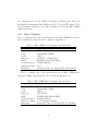
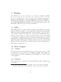
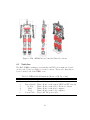
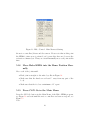
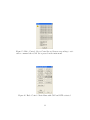
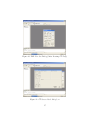
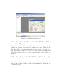
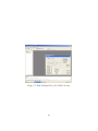
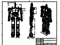
Jaemi Hubo (KHR4) Users Manual Daniel M. Lofaro ([email protected]) December 22, 2009 1 Thanks to: Dr. Paul Oh Dr. JunHo Oh Mr. David Grunberg 2 Contents 1 Overview 1.1 Mechanical . . . . . . . 1.2 Electrical . . . . . . . . 1.2.1 Main Computers 1.2.2 Motor Controllers 1.3 Software . . . . . . . . . 1.3.1 Body Computer . 1.3.2 Head Computer . 2 Communication 2.1 Base Station Computer 2.2 Body Computer . . . . 2.2.1 CAN Bus . . . 2.2.2 RS232 . . . . . 2.2.3 Wireless . . . . 2.2.4 Wired . . . . . 2.2.5 Digital I/O . . 2.3 Head Computer . . . . 2.3.1 RS232 . . . . . 2.3.2 Wireless . . . . 2.3.3 Wired . . . . . 2.3.4 Digital I/O . . 3 Timing 3.1 RTX . . . . . . . 3.2 Body Computer . 3.2.1 Software . 3.2.2 Hardware 3.3 Head Computer . 3.3.1 Software . 3.3.2 Hardware . . . . . . . . . . . . . . . . . . . . . . . . . . . . . . . . . . . . . . . . . . . . . . . . . . . . . . . . . . . . . . . . . . . . . . . . . . . . . . . . . . . . . . . . . . . . . . . . . . . . . . . . . . . . . . . . . . . . . . . . . . . . . . . . . . . . . . . . . . . . . . . . . . . . . . . . . . . . . . . . . . . . . . . . . . . . . . . . . . . . . . . . . . . . . . . . . . . . . . . . . . . . . . . . . . . . . . . . . . . . . . . . . . . . . . . . . . . . . . . . . . . . . . . . . . . . . . . . . . . . . . . . . . . . . . . . . . . . . . . . . . . . . . . . . . . . . . . . . . . . . . . . . . . . . . . . . . . . . . . . . . . . . . . . . . . . . . . . . . . . . . . . . . . . . . . . . . . . . . . . . . . . . . . . . . . . . . . . . . . . . . . . . . . . . . . . . . . . . . . . . . . . . . . . . . . . . . . . . . . . . . . . . . . . . . . . . . . . . . . . . . . . . . . . . . . . . . . . . . . . . . . . . . . . . . . . . . . . . . . . . . . . . . . . . . . . . . . . . . . . . . . . . . . . . . . . . . . . . . . . . . . . . . . . . . . . . . . . . . . . . . . . . . . . . . . . . . . . . . . . . . . . . . . 6 6 6 8 9 9 9 9 . . . . . . . . . . . . 11 11 11 11 11 12 12 12 12 13 13 13 14 . . . . . . . 16 16 16 16 16 17 17 17 4 Parts 18 4.1 Overview . . . . . . . . . . . . . . . . . . . . . . . . . . . . . . 18 4.2 Motor Controller Locations . . . . . . . . . . . . . . . . . . . 18 4.3 Switches . . . . . . . . . . . . . . . . . . . . . . . . . . . . . . 19 3 5 Setup 5.1 Make sure all components are turned off . . . . . . . . . 5.2 Connect Main Power . . . . . . . . . . . . . . . . . . . . 5.3 Install the Battery . . . . . . . . . . . . . . . . . . . . . 5.4 Turn on the 48V Supply . . . . . . . . . . . . . . . . . . 5.5 Lift the Hubo KHR4 . . . . . . . . . . . . . . . . . . . . 5.6 Turn on the Body Computer . . . . . . . . . . . . . . . . 5.7 Log in to the Body Computer . . . . . . . . . . . . . . . 5.8 Run Visual Studio 6 . . . . . . . . . . . . . . . . . . . . 5.9 Open the Program’s Workspace . . . . . . . . . . . . . . 5.10 Set Active Project Configuration as HUBO2 . . . . . . . 5.11 Clean Active Project - HUBO2 . . . . . . . . . . . . . . 5.12 Build All - HUBO2- Win32 RTSS Release . . . . . . . . 5.13 Set Active Project Configuration as khr3win . . . . . . . 5.14 Clean Active Project - khr3win . . . . . . . . . . . . . . 5.15 Build All - khr3win . . . . . . . . . . . . . . . . . . . . . 5.16 Run the Hubo KHR4 Program (khr3win.exe) . . . . . . 5.17 Turn on Sensors and 12V . . . . . . . . . . . . . . . . . . 5.18 Move Hubo KHR4 into the Home Position Manually . . 5.19 Press CAN On in the Main Menu . . . . . . . . . . . . . 5.20 Click OK on the Motor Controller/Sensor Check Screen 5.21 Zero Hubo KHR4’s Joints . . . . . . . . . . . . . . . . . 5.21.1 Click ZPhase in Figure 16 . . . . . . . . . . . . . 5.21.2 Click Search under [LHY ] . . . . . . . . . . . . . 5.21.3 Repeat Step 5.21.1 for each of the joints. . . . . . 5.21.4 Click Exit in the ZPhase dialog box, Figure 17 . . 5.22 Click CAN OFF in the Main Menu, Figure 16 . . . . . . 5.23 Click Exit in the Main Menu, Figure 16 . . . . . . . . . . 5.24 Switch OFF the Sensor switch, Figure 4 . . . . . . . . . 5.25 Lower Hubo to the ground . . . . . . . . . . . . . . . . . 5.26 Wait 10 seconds . . . . . . . . . . . . . . . . . . . . . . . 5.27 Switch ON the Sensor switch, Figure 4 . . . . . . . . . . 5.28 Lift Hubo by repeating Step 5.5 . . . . . . . . . . . . . . 5.29 Start khr3win.exe by repeating Step 5.16 . . . . . . . . . 5.30 Turn the CAN on by repeating Step 5.19 . . . . . . . . . 5.31 Click ZMP Zero Set in the Main Menu, Figure 16 . . . . 5.32 Click FT Null in the ZMP Zero Set Dialog, Figure 19 . . 4 . . . . . . . . . . . . . . . . . . . . . . . . . . . . . . . . . . . . . . . . . . . . . . . . . . . . . . . . . . . . . . . . . . . . . . . . . . . . . . . . . . . . . . . . . . . . . . . . . . . . . . . . . . . . 21 21 21 21 22 22 22 22 22 22 25 25 25 25 26 26 26 26 28 28 30 32 32 32 32 32 35 35 35 35 35 35 35 35 35 35 36 5.33 Do NOT Close ZMP Zero Set Dialog and click FT Show in the Main Menu, Figure 16 . . . . . . . . . . . . . . . . . . . . 5.34 Click F/T Null in the FT Sensor Read dialog box, see Figure 21 5.35 Click Hide in the FT Sensor Read dialog box, see Figure 21 . 5.36 Lower Hubo onto a perfectly level surface . . . . . . . . . . . . 5.37 Click Tilt Show in the Main Menu, Figure 16 . . . . . . . . . 5.38 Make sure the values are correct . . . . . . . . . . . . . . . . . 5.39 Click Start Compensation in the Tilt Read dialog box, Figure 22 5.40 Click Hide in the Tilt Read dialog box, Figure 23 . . . . . . . 5.41 Click Start in the ZMP Zero Set Dialog, Figure 20 . . . . . . . 5.42 Click Set in the ZMP Zero Set Dialog, Figure 24 . . . . . . . . 5.43 Click OK in the pop up box with the text Posture initialization is done, Figure 25 . . . . . . . . . . . . . . . . . . . . . . . . . 5.44 Click Exit in the ZMP Zero Set Dialog, Figure 25 . . . . . . . 5.45 Click Kirk Walking in the Main Menu, Figure 16 . . . . . . . 5.46 Click Walk In Place in the Kirk Walking Dialog box, Figure 26 5.47 Click Stop in the Kirk Walking Dialog box, Figure 26 . . . . . 6 Tutorials 6.1 Upper 6.1.1 6.1.2 6.1.3 6.1.4 6.1.5 6.1.6 6.1.7 6.1.8 Body . . . . . . . . . . . . . . . . . . . . . . . Overview . . . . . . . . . . . . . . . . . . . . Requirements to make a gesture . . . . . . . . Using existing gestures . . . . . . . . . . . . . Creating a Gesture . . . . . . . . . . . . . . . Using the interpolation function . . . . . . . . Adding a gesture to the Hubo code . . . . . . Performing gestures . . . . . . . . . . . . . . . Example: Rise and Lower Arm (Step By Step) A Appendix A.1 Hubo KHR4 Dimensions . . . A.2 Head Computer Specifications A.3 Body Computer Specifications A.4 CAN Card Specifications . . . A.5 CAN Card Specifications . . . 5 . . . . . . . . . . . . . . . . . . . . . . . . . . . . . . . . . . . . . . . . . . . . . . . . . . . . . . . . . . . . . . . . . . . . . . . . . . . . . . . . . . . . . . . . . . . . . . . . . . . . . . . . . . . . . . . . . . . . . . . . . 36 36 38 38 38 38 38 39 39 39 39 39 39 42 42 . . . . . . . . . 44 44 44 44 44 47 48 49 49 50 . . . . . 59 60 62 65 68 70 1 Overview Welcome to the Hubo KHR4 reference manual. Through out this manual you will find information regarding the mechanical, electrical, and software operation of the Hubo KHR4 system. 1.1 Mechanical The Hubo KHR4 has the following mechanical specifications: Page 62 • 6 DOF Per Leg • 41 DOF Total • Aluminum Frame • High Gear Ratio Harmonic Drive Gear Boxes • Maxon Brushless DC Motors The gear ratios for the harmonic drive gear boxes can be found in Table 1. Table 1: Harmonic Drive Gear Ratios Joint Harmonic Drive No Hip Yaw SHD 17 - 100:1 Hip Roll SHD 20 - 160:1 Hip Pitch SHD 20 - 160:1 Knee SHD 20 - 160:1 Ankle Pitch SHD 17 - 100:1 Ankle Roll SHD 17 - 100:1 Trunk Yaw SHD 14 - 100:1 Please refer to Appendix A.1 for the dimensions of the Hubo HKR4. 1.2 Electrical Hubo KHR4 contains two primary x86 based computers, denoted as the Head Computer and the Body Computer, and multiple smart motor controllers. The Body Computer tells all of the motor controllers where to move 6 Figure 1: Hubo KHR4 Joint Direction 7 via communication over two 1MB/s CAN Buses, gathers sensor data from the Inertial Measurement Unit (IMU) and Force-Torque (FT) sensors. The Body Computer will then do all of the calculations to keep the Hubo KHR4 balanced properly. 1.2.1 Main Computers Table 2 contains some of the specifications for the Hubo KHR4 Body Computer. Further Specifications can be found in Appendix A.3. Table 2: Hubo HKR4 Body Computer Specifications Name PCM-3370 CPU Pentium III 933MHz Cache 512Kb Chip Set TwisterT + VT82C686B BIOS AWARD 256kb Flash BIOS System Memory 512MB SDRAM Watchdog Timer 1.6sec Expantion 104-pin PC/104 and 120-pin PCI PC/104-Plus Table 3 contains some of the specifications for the Hubo KHR4 Head Computer. Further Specifications can be found in Appendix A.2. Table 3: Hubo HKR4 Head Computer Specifications Name PCM-3372 CPU Pentium III 1.0GHz Cache 128Kb Chip Set VIA CX700 BIOS AWARD 4Mbit Flash BIOS System Memory 1024Mb DD2533 Watchdog Timer 255 levels interval timer Expantion 104-pin PC/104 and 120-pin PCI PC/104-Plus 8 1.2.2 Motor Controllers The Hubo KHR4 motor controllers consists of three separate motor controllers. • Single Channel Motor Controller/Driver • Dual Channel Motor Controller/Driver • Five Channel Motor Controller/Driver Each of the motor drivers have the same basic firmware on them and take the same basic command however the single channel controller only supports a single motor with quadrature encoder and is used only for the waste. The dual channel supports two motors with quadrature encoders (2x200W) and is used for all of the leg joints and some of the upper body joints. The five channel supports five smaller motors each with a quadrature encoder which is used for the fingers on the right and left hands. All of the motor controllers support current feedback. 1.3 Software Hubo KHR4’s Body Computer and Head Computer both run full versions of Windows XP updated to Service Pack 2. WARNING: Both systems must NOT be updated to Service Pack 3 for the time being due to the Wireless N drivers incompatibility with Service Pack 3. 1.3.1 Body Computer The Body Computer’s main operating system is Windows XP SP2 and the control is compiled using Visual Studios 6 (VS6) and Real Time Extensions 6.5 (RTX 6.5) by Ardence. The RTX system will be explained in greater detail in Section 3.1. The purpose of the Body Computer is to give Hubo KHR4 a dedicated environment for its balancing controller. The Body Computer does not have any .NET framework installed. 1.3.2 Head Computer The Head Computer’s main operating system is Windows XP SP2. The .NET framework 3.5 is currently installed. The purpose of this is so users 9 programing with Microsoft’s Visual Studio 2008 can easily upload custom software. The purpose of the Head Computer is to allow users to add human interaction without risking damaging the stability controller, i.e. the Body Computer. 10 2 Communication The Hubo KHR4 has multiple communication methods. In short the Body Computer communicates with the motor drivers via two 1Mbps CAN Bus networks. The Body Computer can talk to the Head Computer via a serial RS232 level signal. Both of the Body and Head Computers talk to the Base Station Computer via a wireless 802.11n network connection. 2.1 Base Station Computer The Base Station Computer connects to the Body and Head Computers via a Wireless 802.11n connection where the Base Station Computer is connected to the wireless router via a CAT-5e cable the Body and Head Computers are connected to the network via the 802.11n connection. The Base Station Computer also acts as the network storage device for both the Body and Head Computers. The ”Shared Documents” folder on the Base Station Computer is setup as the Z: drive on both the Body and Head Computers. 2.2 Body Computer The Body Computer is the main computer for the Hubo KHR4. This computer communicates with all of the motor drivers via two 1Mbps CAN Buses. All of the lower body joints are located on one CAN Bus and all of the upper body joints are located on the other CAN Bus. The Body Computer is a PCM-3370 PC/104 computer. More information on the PCM-3370 can be found in Appendix A.3. All of the communication methods available on the Body Computer can be found in Table 4. 2.2.1 CAN Bus The CAN Bus is a PCM-3680 Rev A.1 PC/104 Dual Port CAN Interface Module. Information regarding the PCM-3780 Rev A.1 CAN card can be found in Table 5 and in Appendix A.4. 2.2.2 RS232 The Body Computer contains two serial ports, COM1 and COM2. COM1 and COM2 are by default both connected to the Head Computer through 11 Table 4: Hubo KHR4 Body Computer On Board Communication Number of Ports Port Type 2x USB1.1 1x EIDE 1x LPT 1x RS-232/422/485 (COM1) 1x RS232 (COM2) 1x K/B 1x Mouse 2x CAN 1x 10/100 Ethernet (Realtek RTL8139D) internal connections. 2.2.3 Wireless The Body Computer communicates with the Hubo network, called HuNet, via an 802.11n connection. On boot, and login to the user name ”‘hubo,”’ the Body Computer will automatically connect to HuNet. The wireless configuration for the Body Computer can be found in Table 6. 2.2.4 Wired The Body Computer can be plugged directly in to a 10/100 network and accessed. The Body Computer has a Static IP so it can be connected to via a network hub or directly via a crossover cable. The connection information can be found in Table 7. 2.2.5 Digital I/O Unlike the Head Computer the Body Computer does not contain any GPIO, General Purpus IO, pins. 2.3 Head Computer The Head Computer is the secondary compter for the Hubo KHR4. The main purpose of this computer is to act as the processing power for Hubo’s human 12 Table 5: PCM-3680 Rev A.1 PC/104 CAN Card Specifications Ports 2 CAN controller 82C200 CAN transceiver 82C250 Signal support CAN-L, CAN-H Memory address From C800H to EF00H IRQ 3, 4, 5, 6, 7, 9, 10, 11, 12, 15 Isolation voltage 1000 VDC Power consumption +5 V @ 400 mA typical, 950 mA max. Connectors Dual DB-9 male connectors Operating temperature 32 to 122 F (0 to 50 C) PC/104 form factor 3.6” x 3.8” (90 mm x 96 mm) Shipping weight 0.9 lb (0.4 kg) interaction capability. The Head Computer is a PCM-3372 PC/104 computer. More information on the PCM-3372 can be found in Appendix A.2. All of the communication methods available on the Head Computer can be found in Table 8. 2.3.1 RS232 The Head Computer contains two serial ports, COM1 and COM2. COM1 and COM2 are by default both connected to the Body Computer through internal connections. 2.3.2 Wireless The Head Computer communicates with the Hubo network, called HuNet, via an 802.11n connection. On boot, and login to the user name ”‘hubo,”’ the Head Computer will automatically connect to HuNet. The wireless configuration for the Head Computer can be found in Table 9. 2.3.3 Wired The Head Computer can be plugged directly in to a 10/100 network and accessed. The Head Computer has a Static IP so it can be connected to via 13 Table 6: Body Computer SSID Frequency Standard WPA2 Passkey IP Mask Gateway Domain Wireless Configuration HuNet 2.4Ghz 802.11n dasl1234 192.168.0.102 255.255.255.0 192.168.0.1 Hunet Table 7: Body Computer Wired Configuration Network HuNet Standard 10/100 IP (Static) 192.168.0.112 Mask 255.255.255.0 Gateway 192.168.0.1 Domain Hunet a network hub or directly via a crossover cable. The connection information can be found in Table 10. 2.3.4 Digital I/O The Head Computer contains 8x GPIO pins, 4x input and 4x output. Each of these pins are 5V TTL. 14 Table 8: Hubo KHR4 Body Computer On Board Communication Number of Ports Port Type 6x USB2.0 1x EIDE 2x SATA 1x RS-232/422/485 (COM1) 1x RS232 (COM2) 1x K/B 1x Mouse 8x GPIO (4 input/4 output) 1x 10/100 Ethernet (Intel 82551ER) Table 9: Head Computer SSID Frequency Standard WPA2 Passkey IP Mask Gateway Domain Wireless Configuration HuNet 2.4Ghz 802.11n dasl1234 192.168.0.103 255.255.255.0 192.168.0.1 Hunet Table 10: Head Computer Wired Configuration Network HuNet Standard 10/100 IP (Static) 192.168.0.113 Mask 255.255.255.0 Gateway 192.168.0.1 Domain Hunet 15 3 Timing Hubo KHR4 uses two hard real-time loops, running at 100Hz and 500Hz, for motor commands and control and sensor data acquisition respectively. These two hard real-time loops are maintained by the the IntervalZero RTX Real-Time Extension for Windows (RTX), formerly Ardence RTX. The version that Hubo KHR4 runs is RTX 6.5. For more information please visit IntervalZero RTX home page1 for more information. 3.1 RTX IntervalZero RTX2 is a hard real-time solution for the Windows operating system. RTX is used with C, or C++ in the Microsoft Windows environment. When a program is written using RTX a hard real-time loop/loops can be crated. When compiled and run these loops will not run within Windows, it will run ”‘Next to Windows.”’ This means that if Windows crashes the RTX loop will still be running just fine. Because this system runs on a system running Microsoft Windows the majority of the deceives that with windows will work with the RTX system. This means that as long as it works with Windows it will work with our real-time system. For more information on RTX please see Appendix A.5. 3.2 3.2.1 Body Computer Software The Body Computer runs the RTX system as described in Section 3.1. This system runs two hard real-time loops, 100Hz and 500Hz. The 100Hz loop is for the motor controller commands, and the 500Hz loop is for the sensor data acquisition. 3.2.2 Hardware The Body Computer contains a 1.6sec interval Watchdog timer. This is setup via software. 1 2 IntervalZero RTX: http://www.directinsight.co.uk/products/venturcom/rtx.html IntervalZero RTX: http://www.directinsight.co.uk/products/venturcom/rtx.html 16 3.3 3.3.1 Head Computer Software The Head Computer does not contain any form of hard real-time interface. 3.3.2 Hardware The Head Computer contains a 255 levels interval Watchdog timer. This is setup via software. 17 Figure 2: Hubo KHR4 Main Body given in front, side, and cartesian views 4 Parts This section will explain the main parts of the Jaemi Hubo KHR4. Please note that the figures in this section will be used in other sections as references. 4.1 Overview The Hubo KHR4 series is a 4” 3’ tall humanoid robot. Figure 2 shows the Hubo KHR4 in the front, side and cartesian view points. This picture will be used when describing each part in this section. 4.2 Motor Controller Locations The motor controllers are located all over the KHR4’s body. Please see Figure 3 for the locations of the motor controllers/drivers. 18 Figure 3: Hubo KHR4 Motor Controller/Driver Locations 4.3 Switches The Hubo KHR4’s primary power switches and DC power input are located on her back. Please see Figure 4 for the locations. Please note that this is located on the back of the KHR4’ torso. Table 11: KHR4 Switch Definitions (Down = Off, Up = On) Number Name Function 1 Audio Turns off and on the Audio 2 Sensor Switch Turns off and on the sensors (IMU and FT sensors) 3 12 Volt Turns off and on the 12V to the motor drivers 4 Head Turns off and on the head computer 5 Body Turns off and on the body computer 6 Power Cable Keyed 48V DC power cable 19 Figure 4: Hubo KHR4 power switches and DC power input locations 20 5 Setup This section explains how to setup and run the main program for Jaemi Hubo KHR4 using the HUBO2 R1.5 software version. When setting up the KHR4 please DO NOT skip a step or press a wrong button. If you press an incorrect button or accidentally skip a step please do the following: 1. Lift the KHR4 off the ground using the hoist 2. Turn off the 12V and Sensors via the switches denoted in (ADD SWITCH SECTION HERE dan.3e.org) 3. Shut the program down 4. Start setting the KHR4 up from the beginning In order to successfully setup and run the Jaemi Hubo KHR4 the following needs to be done in their given order to ensure optimal functionality. 5.1 Make sure all components are turned off Go to the back panel of the Hubo KHR4, see Figure 4, and make sure all of the switches are down. 5.2 Connect Main Power Plug in the keyed 48V DC power connector located on the KHR4’s back, Figure 4. Note: MAKE SURE THE 48V IS POWERED OFF BEFORE YOU PLUG IT IN. 5.3 Install the Battery Insert one of the KHR4’s 48V batteries (optional) Please Note: 1. If no battery the DC supply must always be turned on and connected during operation 2. After calibration starts you CAN NOT install the battery 21 5.4 Turn on the 48V Supply Turn on the power to the 48V DC power supply hooked up the the Hubo KHR4. 5.5 Lift the Hubo KHR4 Lift the KHR4 by the hooks on her shoulders until she is 3” or more off the ground. 5.6 Turn on the Body Computer To turn on the head computer flip body computer switch, switch 5 in Figure 4, to the ON position. At this point the KHR4 is booting up the body computer. On boot the body computer will automatically connect to wireless network HuNet as described in Section 2.2.3. 5.7 Log in to the Body Computer Log in to the body computer using a RDP (Remote Desktop Protocol) program such as Windows Remote Desktop or the Linux rdesktop client. Note: You must have a remote desktop screen resolution of at least 1024x768 to ensure full functionality. 5.8 Run Visual Studio 6 Run Visual Studio 6 through the shortcut on the desktop, see Figure 5. You must use this link because the KHR4 runs the Windows XP system on a limited account by default. This shortcut will run the program as the admin which is needed to successfully run the Windows RTX later on. At this point you should see this screen, see Figure 6. 5.9 Open the Program’s Workspace Go to the file menu and click on Open Workspace Figure 7 should now show on your screen. Choose the HUBO2.dsw in the HUBO2 R1 5 Current Version folder. This is currently the latest version of the software. However this might be updated in the future. At this point your screen should look like Figure 8. 22 Figure 5: Visual Studio 6 with Run As Admin set Figure 6: Visual Studio 6: Main Window 23 Figure 7: Visual Studio 6: Open the HUBO2.dsw Workspace Figure 8: Visual Studio 6: HUBO2.dsw Workspace 24 Figure 9: Visual Studio 6: Set Active Project Configuration as HUBO2 Win32 RTSS Release 5.10 Set Active Project Configuration as HUBO2 Go to Build → Set Active Configuration and choose HUBO2 - Win32 RTSS Release, see Figure 9. 5.11 Clean Active Project - HUBO2 Clean the active project HUBO2 - Win32 RTSS Release by going to Build → Clean. 5.12 Build All - HUBO2- Win32 RTSS Release Build the HUBO2 - Win32 RTSS Release by going to Build → Build All. 5.13 Set Active Project Configuration as khr3win Go to Build → Set Active Configuration and choose khr3win - Win32 Release, see Figure 10. 25 Figure 10: Visual Studio 6: Set Active Project Configuration as khr3win Win32 Release 5.14 Clean Active Project - khr3win Clean the active project khr3win - Win32 Release by going to Build → Clean. 5.15 Build All - khr3win Build the khr3win - Win32 Release by going to Build → Build All. At this point your screen should look like Figure ?? 5.16 Run the Hubo KHR4 Program (khr3win.exe) To run the Hubo KHR4 program (knr3win.exe) click on the ! on the top right hand corner of the VS6 screen as denoted in Figure 12. At this point the main window of the khr3win.exe program will come up on the screen, see Figure 13. 5.17 Turn on Sensors and 12V Switch the Sensors and 12V switches to the on position. The Sensors and 12V switches are switches 2 and 3 in Figure 4 respectively. This will activate 26 Figure 11: Visual Studio 6: Compiled the Hubo KHR4 code (Note: the 55 warnings is expected) Figure 12: Visual Studio 6: Run the Hubo KHR4 program (khr3win.exe) by clicking the ! 27 Figure 13: Hubo Control: Main Menu at Startup the motor controllers/drivers and the sensors. Please note that at this point the KHR4’s joints are not activated yet because they have not been set the activation command yet. Thus you can still manually move each joint at this time. 5.18 Move Hubo KHR4 into the Home Position Manually Move each of the joints until: • Each joint is straight to the naked eye like in Figure 14. • Make sure that the hands are at least 1” away from any part of the body • Make sure that the feed are a minimum of 1” apart 5.19 Press CAN On in the Main Menu Press the CAN On button in the Main Menu of the Hubo KHR4 program, see Figure 13 and wait until the motor controllers and sensors respond, see Figure 15. Note: 28 Figure 14: Hubo KHR4 Hanging greater then 3” above the ground with limbs straight to the naked eye. 29 1. All of the JMC Boards should reply with “JMCBoard is ready for 10 msec Int. time.” 2. All of the EJMC boards should reply with “EJMC Board is ready for 10 msec Int.time.” 3. The Sensors will respond with the following (a) 0th Sensor Boarc is ready. (b) 1th Sensor Boarc is ready. (c) 2th Sensor ———– (d) 3th Sensor ———– (e) 4th Sensor Boarc is ready. (f) 5th Sensor Boarc is ready. (g) 6th Sensor ———– 4. The end result should look like Figure 15. If one or more of the motor controllers or sensors did not respond do the following: 1. Click the OK button current screen, see Figure 15. 2. Click CAN Off on the Main Menu, Figure 13. 3. Close the Main Menu by clicking the x in the top left, Figure 13. 4. Start the program again by pressing the ! as seen in Figure 12. 5. Repeat starting from Step 5.19. 5.20 Click OK on the Motor Controller/Sensor Check Screen On the motor controller/sensor check screen, Figure 13, click the OK button on the bottom. You will now see the main menu again however this time the button that said CAN On now says CAN Off and RTX OFF, see Figure 16. This means that both the CAN and the RTX systems are now activated. 30 Figure 15: Hubo Control: Motor Controller and Sensors responding to activation command after CAN On is pressed in the main menu. Figure 16: Hubo Control: Main Menu with CAN and RTX activated 31 5.21 Zero Hubo KHR4’s Joints 5.21.1 Click ZPhase in Figure 16 This will open up the Zero Phase dialog box, see Figure which will allow the user to zero and activate each of Hubo’s joints. 5.21.2 Click Search under [LHY ] This will make Hubo’s Left Hip Yaw [LHY ]: • Highlight the word Searching, as seen in Figure 18. • Move until it hits the limit switch • Then move back until it hits it’s first index point on it’s encoder • Now the motor controller knows exactly where it is and now moves to the pre-defined offset values. This position is it’s home/zero position. If the home position was successfully found then the OK icon will be highlighted. If it did NOT succeed in finding it’s home position then the FAIL! icon will be highlighted. If the system did NOT succeed in finding it’s home position: • Check to make sure the joint is close to it’s home position, if it is not change it’s position by hand. • Click Search again. 5.21.3 Repeat Step 5.21.1 for each of the joints. Please note that you can only do ONE joint at a time. Make sure to wait until the previous joint has OK highlighted BEFORE moving on to the next joint. 5.21.4 Click Exit in the ZPhase dialog box, Figure 17 The only joints that will be activated will be the joints that you successfully found a home position for when you exit the program. We need to exit the program to reset the encoder values. 32 Figure 17: Zero Phase (ZPhase) Dialog Box: Allows user to zero and activate each of Hubo’s joints 33 Figure 18: Zero Phase (ZPhase) Dialog Box: Left Hip Yaw [LHY ] Searching for home position 34 5.22 Click CAN OFF in the Main Menu, Figure 16 This will shut down the CAN communication. 5.23 Click Exit in the Main Menu, Figure 16 This will close the program. 5.24 Switch OFF the Sensor switch, Figure 4 This will turn off the sensors only. We need to do this to recalibrate the sensors. 5.25 Lower Hubo to the ground Lower Hubo to the ground so she is on her feet and has about an inch or so of slack in her hoist cables connected to her. 5.26 Wait 10 seconds Make sure Hubo is not moving and wait 10 seconds 5.27 Switch ON the Sensor switch, Figure 4 We are now turning on the sensors while Hubo is stationary on the ground so her sensors are zeroed properly. 5.28 Lift Hubo by repeating Step 5.5 5.29 Start khr3win.exe by repeating Step 5.16 5.30 Turn the CAN on by repeating Step 5.19 5.31 Click ZMP Zero Set in the Main Menu, Figure 16 At this point Hubo will move in to her zero default crouched position. Remember Hubo is still hanging at this point. The ZMP Zero Set dialog will now open, Figure 19. 35 Figure 19: ZMP Zero Set Dialog (Before Pressing FT Null ) 5.32 Click FT Null in the ZMP Zero Set Dialog, Figure 19 This action will null the force torque (FT) sensors in Hubos ankles and right wrist. Note that the button that previously said FT Null now says Start, see Figure 20. 5.33 Do NOT Close ZMP Zero Set Dialog and click FT Show in the Main Menu, Figure 16 The new dialog box that opens is called FT Sensor Read dialog box, see Figure 21 5.34 Click F/T Null in the FT Sensor Read dialog box, see Figure 21 This will null the FT sensors again. You must do this a minimum of one time. Make sure that the values in the left boxes of Mx, My, Fz for the left and right feet and the wrist are all between -4 and 4 before. Each time you 36 Figure 20: ZMP Zero Set Dialog (After Pressing FT Null ) Figure 21: FT Sensor Read dialog box 37 press F/T Null the system will take the difference between the current value and zero and add that to the FT offset. 5.35 Click Hide in the FT Sensor Read dialog box, see Figure 21 Make sure that you click Hide and NOT Close. If you click Close by accident you are required to turn turn off the 12V and Sensors and start the whole process over again from Step 5.16. 5.36 Lower Hubo onto a perfectly level surface Lower Hubo on to a perfectly level service and make sure that there is is about three inches of slack in her safety cord. 5.37 Click Tilt Show in the Main Menu, Figure 16 After clicking Tilt Show the Tilt Read dialog box will come up, Figure 22. 5.38 Make sure the values are correct Make sure that the Pitch and Roll values are correct. If they are not Hubo will need to be recalibrate before proceeding. Proper Values: • Incl. (Roll): Between -10 and 10 • Incl. (Pitch): Between 70 and 100 If the pitch and roll values do not fall between the above values you may NOT continue and you must lift Hubo up, turn off her 12V and sensors and then recalibrate before proceeding. 5.39 Click Start Compensation in the Tilt Read dialog box, Figure 22 This will help the system compensate for a slight roll and pitch errors. After pressing Start Compensation the Angle (Pitch) and Angle (Roll) will start to change value, see Figure 23. Let this run for about 20 seconds. 38 5.40 Click Hide in the Tilt Read dialog box, Figure 23 Make sure that you click Hide and NOT Close. If you click Close by accident you are required to turn turn off the 12V and Sensors and start the whole process over again from Step 5.16. 5.41 Click Start in the ZMP Zero Set Dialog, Figure 20 When Start is pressed Hubo starts to move her waist around slightly looking for a specific position. The values for X-ZMP and Y-ZMP will be constantly changing, see Figure 24. Wait until X-ZMP and Y-ZMP are within 0.3 of their respective targets, this normally takes from 3 to 5 minutes. Target Values: • X-ZMP = 10.000 • Y-ZMP = 0.000 Note: Make sure that X-ZMP and Y-ZMP are within their 0.3 margin of error before you continue. 5.42 Click Set in the ZMP Zero Set Dialog, Figure 24 By pressing Set you are saving the current ZMP values. A notification box will now pop up stating that your Posture initialization is done, see Figure 25. 5.43 Click OK in the pop up box with the text Posture initialization is done, Figure 25 5.44 Click Exit in the ZMP Zero Set Dialog, Figure 25 5.45 Click Kirk Walking in the Main Menu, Figure 16 The Kirk Walking dialog box will appear, see Figure 26. 39 Figure 22: Tilt Show dialog box Figure 23: Tilt Show dialog box (Post Pressing Start Compensation Button) 40 Figure 24: ZMP Zero Set Dialog (After Pressing Start) Figure 25: ZMP Zero Set Dialog (After Pressing Set) 41 Figure 26: Kirk Walking Dialog Box 5.46 Click Walk In Place in the Kirk Walking Dialog box, Figure 26 This will make Hubo walk in place. This action sets many flags needed for walking and gestures. It is required to walk in place before walking for the first time AND before entering into the Gestures menu. The dialog box now grays out all movement boxes except for Stop while it is moving. This is because you are required to stop your motion before doing another, see Figure 27. 5.47 Click Stop in the Kirk Walking Dialog box, Figure 26 This will cause Hubo to stop walking in place. All of the proper flags are now set and you may continue on with your demonstration. This is the end of the setup phase. 42 Figure 27: Kirk Walking Dialog Box While Moving 43 6 Tutorials 6.1 6.1.1 Upper Body Overview The movements of Hubo khr4 are called gestures. Gestures are position information for one or more joints that tell the Hubo where to position those joints at which times. Gestures can be as simple as a single joint movement or as complicated as a full dance routine, and several of both kinds are already present in the Hubo code. Gestures must be programmed before the robot is run; they can not be modified on the fly. 6.1.2 Requirements to make a gesture In order to produce a for the Hubo khr4, three processes must be completed: 1. The gesture must be generated. This requires the user to visualize where they want the robot to move and then use the Hubo’s syntax to make a command that will achieve the desired motion. In this step the hardware and mechanics of the Hubo must also be considered to ensure that the Hubo can perform the motion. 2. The gesture must be inserted into the Hubo code. Various functions and pages must be updated so that the gesture is fully integrated with all of the existing HUBO components. 3. The gesture must be triggered. The most common way to do this is from the GUI. However, command-line options are also possible. The GUI is generally preferable, for ease and for greater transparency when running demonstrations. The priority concern when creating a gesture must be the safety and stability of the Hubo. It is a fragile and expensive piece of equipment, and a wrong move could either damage a motor or topple the robot. 6.1.3 Using existing gestures For demonstration purposes or for testing, the user may wish to perform the Hubo khr4’s existing gestures. This can be done directly from the GUI or from the command line. 44 Care should be taken to make sure that the startup procedure for the Hubo has already been performed so that variables and flags are correctly set. Failure to ensure this could cause damage to the Hubo. 1. Click on the ’kirk walking’ button on the GUI. This sets several flags to prepare the Hubo for gesturing. 2. Before pressing any other button press ’Walk in Place’. Let Hubo walk in place for a few steps and then press ’Stop’. This will need to be done before entering the ’Gestures’ menu also. For leg gestures and walking: 1. In the ’kirk walking’ dialogue set the ’step size’ box to whatever value the user wishes below 120. This variable controls the length of the Hubo’s steps. 60 is a good number if you have no preference. 2. Ensure that nothing is in the way of the Hubo, that all observers have been cautioned not to touch it, and that the terrain is flat. 3. Select ’Forward,’ ’Backward,’ ’CW,’ or ’CCW.’ This will have the HUBO begin to walk or turn in the direction instructed. Note: These buttons set flags to make the Hubo begin running position calculation functions for walking. These functions adjust many of the Hubo’s position variables and also control what statements are executed in the TimerHandler() function. 4. When finished, select ’stop.’ 5. Note: You MUST click ’stop’ before choosing a different lower body gesture. The Hubo must not be moving when the new gesture is chosen. Upper body gestures: 1. Walk in place and then press ’stop’ as described above. This will make sure the Hubo is in the proper mode before switching to upper body gestures. 2. Select the ’gesture’ button. Note: This sets flags to enable the MotionPlay() functions and also the wrist and shoulder testing gestures. 3. At this point a new window will open. This is the ’Gestures’ window. 45 Gripping: 1. Set the grip power box to between 1 and 5, depending on how tight a grip you want. Also select the ’right hand’ or ’left hand’ checkboxes to control which hand grips. 2. Select ’Hold on Hand’ to close the hand. 3. ’Hold on Hand’ and ’Hold off Hand’ disable many other buttons on the gesture panel so that the Hubo does not do too many things at once. To enable them, select the ’Motion Button Activation’ button. Hand Shaking: 1. First select the ’FT Show’ button and make sure that the FT variables are within certain bounds. Mx, My, and Fz should all be less than 20, otherwise the robot may destabalize. These variables relate to the robot’s balancing and its force sensors in its feet. 2. Click ’Start Shake Hands’ to start shaking hands. Note: This will cause Hubo to lift her right arm/hand and put it into a shaking position. 3. At this point the force torque (FT) sensors in the wrist are activated. When the user puts their hand in Hubo’s right hand and move it up and down Hubo will follow. 4. When done click ’Stop Shake Hands’. Hubo’s arm/hand will then return it it’s default position Wrist Moving: 1. Set several values in the write boxes. Select 10mm for the distance box, as this is a good range for the robot’s wrist. Select between 1 and 4 Hz in the speed box. The Hubo should not go faster than 4 Hz, otherwise it may damage itself. Finally, select a mode. 2. Mode 1 rotates the wrist, mode 2 makes it go in circles, and mode 3 makes it rise and fall. 3. Select ’Go’ to begin wrist motion and ’Stop’ to stop it. For other gestures in the gesture menu select the appropriate button. Hubo will move accordingly without requiring a stop command. Note: Wait until the gesture is completed until pressing a new gesture. DO NOT press multiple gestures at one. 46 6.1.4 Creating a Gesture Each joint that can be moved on the Hubo is indexed in several matrices with a three letter variable. The joints are listed below in Table ??. Table 12: Hubo Joint Static Joint Index Name 3 Left Shoulder Pitch 4 Left Shoulder Yaw 5 Left Shoulder Roll 6 Left Elbow Bend 7 Left Wrist Pitch 8 Left Wrist Roll 9 Right Shoulder Pitch 10 Right Shoulder Yaw 11 Right Shoulder Roll 12 Right Elbow Bend 13 Right Wrist Roll 14 Right Wrist Pitch Variable Values Static Variable Value LSP LSY LSR LEB LWP LWR RSP RSY RSR REB RWR RWP To create the gesture, first consider where exactly you want the robot to move, and in what time span. Make sure that the robot has at least 0.1 seconds for every ten degrees. Less time than that could damage the Hubo’s joints. Next consider the direction that you want the Hubo’s joints to move. Refer to Figure 1 to determine whether this direction will be positive or negative for each joint. For example, having the Hubo’s right shoulder swing back is positive yaw and thus a positive joint angle. Having the arm swing forward is negative yaw and thus a negative angle. After you have determined all of this, create your gesture. Use the function seen in Program 1 to form each segment of the gesture for each joint. Then combine them to form a full gesture. A detailed description of how to use this function follows. Program 1 Half Cos Function FTN_half_1_cos(magnitude,time,start_time,duration,0,0,&result) 47 6.1.5 Using the interpolation function The function’s parameters for the half cos function found in Program 1 are defined in Table 13. Table 13: Half Cos function Parameter Definitions Parameter Definition magnitude Indicates direction of gesture. 1 or -1. time Indicates what variable is used to mark time. Default is ’time’ start time Indicates time that gesture begins. duration Indicates length of gesture in ms. &result Pointer to where the answer is stored. So, to move a joint in the positive direction for 0.2 seconds after a 0.1 second rest, the example command can be found in Program 2. Program 2 Half Cos Function Start Time = 0.1sec, Rise Time = 0.2sec FTN_half_1_cos(1.0f,time,100,200,0,0,&result[1]); To set the magnitude of the movement in degrees, multiply the result variable by the desired number of degrees. To move the joint in the same way as in Program 2, but for 30 degrees, the example command can be found in Program 3. Program 3 Half Cos Function Program 2 set to move 30deg FTN_half_1_cos(1.0f,time,100,200,0,0,&result[1]); Res[0] = (float)30.*result[1]; To assign this motion to a particular joint, place the magnitude-scaled values in the UpperMovement matrix at the appropriate index from Table ??. So, to assign the above motion to the left elbow, the example command can be found in Program 4. To set multiple joints, simply write commands for multiple UpperMovement values in a row. To set more complex gestures, such as a joint moving forwards and then returning to its starting position, run the FTN half 1 cos() function numerous times and sum the result variables, the example command can be found in Program 5. 48 Program 4 Half Cos Function moving the left elbow from 0det to 30deg FTN_half_1_cos(1.0f,time,100,200,0,0,&result[1]); Res[0] = (float)30.*result[1]; UpperMovement[LEB] = Res[0]; Program 5 Half Cos Function moving the left elbow from 0det to 30deg then back to 0deg FTN_half_1_cos(1.0f,time,100,200,0,0,&result[1]); FTN_half_1_cos(-1.0f,time,400,200,0,0,&result[2]); //No overlap Res[0] = (float)30.*(result[1]+result[2]); UpperMovement[LEB] = Res[0]; 6.1.6 Adding a gesture to the Hubo code First examine the Gesture.cpp file in the khr4 code. Find a button which does not have a gesture, or whose gesture you will not be using. Find the corresponding OnButtonMotion() function for that button. Set T to the length of your gesture in units of 10 ms. Ignore any comments in the code about T REQUIRED to be a multiple of 3. Make a note of the value of the MotionNo variable. Now examine the Profile.cpp file in the Hubo code. This file contains most of the gestures that the Hubo uses. When flags are set (such as when buttons are pushed on the GUI), TimerHandler() calls functions in this file to run and update the Hubo’s motors. The motors then move to new position as the gestures require. Identify the PROF MotionPlay[x] function, where [x] is the MotionNo from the button function. Scroll until you see a line marked ’start edits.’ Change the FTN half 1 cos(), the summing, and the UpperMovement lines to match the gesture that you want to implement. This implements the gesture on Hubo. 6.1.7 Performing gestures New gestures are implemented in the same way as the preset gestures. The same commands are used to set up the Hubo, and then similar buttons are pushed. 49 The main difference between new gestures and preset gestures is that, by default, no boxes exist to scale the Hubo’s gestures. As a result, all of the gestures must be preset in their entirety before the Hubo is run. It may behoove the operator to make several similar gestures with different magnitudes or slight variations to show off the Hubo’s control and versatility, but one gesture cannot be adjusted in real-time for this purpose. To work around this, the user may find it desirable to add some scaling boxes. These boxes must be added to the GUI and then set up in the khr4 code to be checked every time the OnTimer() function runs. The values should then be passed to the Gesture.cpp and Profile.cpp files as needed. 6.1.8 Example: Rise and Lower Arm (Step By Step) The goal of this example is to show you how to make a simple gesture. In this case we are going to be raising and lowering Hubo’s left and right arms. To complete this task please do the following: 1. Make a copy of the entire Hubo2 project and increment the version number. 2. Open HUBO2.dsw in the project you just incremented the version number in, see Figure 28. 3. Goto Build → Set Active Configuration → khr3win Release. This will set the active project as the front end and NOT the RTX. 4. Goto Resource View, see Figure 29. 5. Double click on IDD DIALOG GESTURE, see Figure 30. 6. Double click on the button you want to edit. In this example we will be editing BLANK 2, see Figure 31. 7. You will now be in the potion of the code that controls the functionality of the button. In this case we are dealing with Button 31. Here it is important that you note what motion number. In this case MotionNo = 29. Also note the line T =900. This means that the total time of this motion will last 900 cycles where each cycle is 10ms. Thus this motion will last for 9000ms or 9sec, see Figure 32. 50 8. Next go to File View and open PROFILE.cpp in the HUBO2 files → Source Files section, see Figure 33 9. When in HUBO2 files → Source Files → PROFILE.cpp find the PROF MotionPlay29 section. The ending is 29 because in the previous section our MotionNo was 29. The ending number is what ever the MotionNo is equal to. Make sure that in this section that MotionNo is equal to the same value as it is in the previous section. In this case MotionNo = 29, see Figure 34. 10. Next scroll down to the comment //–==[ Start edit ]==–// This is the start of the ONLY AREA THAT YOU EDIT TO MAKE A GESTURE. The commented section //–==[ End edit ]==–// is the end of the area that you edit to make gestures. ONLY EDIT BETWEEN THESE TWO COMMENTED AREAS, see Figure 35 11. To make a movement profile you need to use the FTN half 1 cos() function. The point of this function is to allow for movement of the joints from the joints current location to a desired location in a smooth manner. This is done to reduce extremely fast and potentially damaging effects of step function inputs. 12. We will now create a movement of the right and left arms. Figure ?? is the timing diagram for the movement. All noted ticks are in increments of 10ms. The top graph shows the desired movement of the Right Shoulder Pitch (RSP) and the bottom graph shows the timing diagram of the Left Shoulder Pitch (LSP). • The X axis is time which is kept track of by the variable time and increases in 10ms increments every cycle. • The Y axis is command angle for the joint defined in degrees. • The flat section at the top of each bump is the desired target angle. • The curved section is the use of the FTN half 1 cos() function which is used to get to that angle. • Please see the list of steps below to come up with the desired trajectory for the RSP and LSP. Follow these steps to make the desired trajectory: 51 1. At time = 100 to time = 200 RSP moves from 0 deg to 90 deg. Code: FTN_half_1_cos( 1.0f,time, 100,100,0,0,&result1[0]); 2. At time = 300 to time = 400 LSP moves from 0 deg to 90 deg. Code: FTN_half_1_cos(1.0f,time, 300,100,0,0,&result1[1]); 3. At time = 500 to time = 600 RSP moves from 90 deg to 0 deg. Code: FTN_half_1_cos(-1.0f,time, 500,100,0,0,&result2[0]); 4. At time = 700 to time = 800 LSP moves from 90 deg to 0 deg. Code: FTN_half_1_cos(-1.0f,time,700,100,0,0,&result2[1]); 5. At this point all trajectories are in percentage of the desired angle. Because the desired final angle for each the LSP and RSP is 90 deg the function will be multiplied by the value 90 deg. 6. For the RSP the full movement is made by adding result1[0] and result2[0] together. Code: res[0] = (float)(90.*(result1[0]+result2[0])); 7. For the RSP the full movement is made by adding result1[1] and result2[1] together. Code: res[1] = (float)(90.*(result1[1]+result2[1])); 8. Now the trajectory data is stored in res as res[0] for the RSP and res[1] for the LSP. 9. Next the trajectories need to be applied to the trajectories in res to the proper joints. 10. For the Right Shoulder Pitch RSP. Code: UpperMovement[RSP] = res[0]; 52 Figure 28: Open HUBO2.dsw 11. For the Left Shoulder Pitch LSP. Code: UpperMovement[LSP] = res[1]; 12. BE SURE TO VERIFY THE TRAJECTORY BEFORE RUNNING IT ON HUBO 13. See Program 6 for all of the above code put together. 53 Figure 29: Goto Resource View Figure 30: Double click on IDD DIALOG GESTURE 54 Figure 31: Double click on the button you want to edit. In this example we will be editing BLANK 2. Figure 32: You will now be in the potion of the code that controls the functionality of the button. In this case we are dealing with Button 31. Here it is important that you note what motion number. In this case MotionNo = 29. Also note the line T =900. This means that the total time of this motion will last 900 cycles where each cycle is 10ms. Thus this motion will last for 9000ms or 9sec. 55 Figure 33: Next go to File View and open PROFILE.cpp in the HUBO2 files → Source Files section. Figure 34: When in HUBO2 files → Source Files → PROFILE.cpp find the PROF MotionPlay29 section. The ending is 29 because in the previous section our MotionNo was 29. The ending number is what ever the MotionNo is equal to. Make sure that in this section that MotionNo is equal to the same value as it is in the previous section. In this case MotionNo = 29. 56 Figure 35: Next scroll down to the comment //–==[ Start edit ]==–// This is the start of the ONLY AREA THAT YOU EDIT TO MAKE A GESTURE. The commented section //–==[ End edit ]==–// is the end of the area that you edit to make gestures. ONLY EDIT BETWEEN THESE TWO COMMENTED AREAS. Figure 36: We will now create a movement of the right and left arms. This is the timing diagram for the movement. All noted ticks are in increments of 10ms. The top graph shows the desired movement of the Right Shoulder Pitch (RSP) and the bottom graph shows the timing diagram of the Left Shoulder Pitch (LSP). Note: The X axis is time which is kept track of by the variable time and increases in 10ms increments every cycle. The Y axis is command angle for the joint defined in degrees. 57 Program 6 Final program used to make the RSP and LSP move to 90deg and back. This code is to be placed between //–==[ Start edit ]==–// and //–==[ End edit ]==–// as seen in Figure 35 FTN_half_1_cos( 1.0f,time, 100,100,0,0,&result1[0]); FTN_half_1_cos( 1.0f,time, 300,100,0,0,&result1[1]); FTN_half_1_cos(-1.0f,time, 500,100,0,0,&result2[0]); FTN_half_1_cos(-1.0f,time,700,100,0,0,&result2[1]); res[0] = (float)(90.*(result1[0]+result2[0])); res[1] = (float)(90.*(result1[1]+result2[1])); UpperMovement[RSP] = res[0]; UpperMovement[LSP] = res[1]; 58 A Appendix 59 A.1 Hubo KHR4 Dimensions 60 4 3 1 181.87 214.50 D 181.59 289.47 107.00 179.14 230.00 120.00 88.43 79.50 303.87 D 2 C 300.03 C B 94.97 300.38 B 130.00 220.00 DRAWN RJG 9/23/2009 Drexel Autonomous Systems Lab CHECKED TITLE QA A MFG A JAEMI HUBO DIMENSIONS APPROVED SIZE C SCALE 4 3 2 REV DWG NO HUBO KHR-4 Rev_01 SHEET 1 1 OF 1 A.2 Head Computer Specifications 62 PCM-3370 36-bit TFT LV Intel® Pentium® III PC/104-Plus CPU Module Features PC/104+ ULV Intel® Celeron® 400/650 MHz Fanless, LV Pentium® III 800/933 MHz Inverter Power Chipset: VIA® VT8606/TwisterT and VT82C686B Fan IR VGA/LCD controller with optimized Shared Memory Architecture (SMA) LAN 4 x AGP VGA/LCD & LCD controller up to 1024 x 768 422/485 CRT USB IDE +5 V and +12 V power supply required 10/100Mbps PCI Ethernet interface, supports wake-on-LAN COM2 (5 V) supports power line connected on pin 9 COM2 LPT PC/104 and PC/104-Plus expansion connector Power Support for CompactFlash® Card (CFC) Type I Socket COM1 1.6 sec – interval Watchdog timer PC/104 KB/Mouse 1 SODIMM socket supports up to 512 MB SDRAM ATX Standby power Specifications Mechanical and Environmental General CPU 2nd Cache Memory System Chipset BIOS System Memory Power Management SSD Watchdog Timer Expansion Interface Onboard ULV Intel Celeron 400/650 MHz Fanless, or LV Pentium III 933 (800 MHz optional) 256 KB on ULV Celeron/512 KB on Pentium III VIA VT8606/TwiserT + VT82C686B AWARD® 256 KB Flash BIOS 1 x SODIMM socket, supports up to 512 MB SDRAM Supports Advanced Power Management Supports CompactFlash Card Type I 1.6 sec – interval Watchdog timer, set up by software, jumperless selection, generates system reset or IRQ11 104-pin 16-bit PC/104 module connector and 120-pin PCI PC/104-Plus module connector I/O I/O Interface USB IrDA I/O Expansion 1 x EIDE, 1 x LPT, 1 x RS-232/422/485, 1 x RS232, 1 x K/B, 1 x Mouse 2 Universal Serial Bus 1.1 compliant ports Share with COM2, transfer rate up to 1.15 Mbps Support for + 5 V FAN, speed detect connector, Heat, Fan speed Ethernet Chipset Speed Interface Realtek RTL8139D 10/100 Mbps 10/100Base-T 1 x RJ-45 Display Chipset *VIA VT8606 4X AGP controller, supporting CRT PCM-3370F: 18/24/36 bit TTL interface PCM-3370E: 18/24 bit TTL interface and 36 bit dual channel LVDS Dimension (L x W) Weight Operating Temperature Operating Humidity 96 x 115 mm 0.162 kg (with heat sink) 0 ~ 60° C 0% ~ 90% relative humidity, non-condensing Power Power Supply Voltage +5 V ±5%, +12 V ±5% Power Consumption Typical: 2.43 A @ +5 V (ULV Celeron 400 MHz CPU) 2.83 A @ +5 V (ULV Celeron 650 MHz CPU) 3.50 A @ +5 V (LV Pentium III 933 MHz CPU) 0.02 A @ +12 V (ULV Celeron 400 MHz CPU) 0.02 A @ +12 V (ULV Celeron 650 MHz CPU) 0.02 A @ +12 V (LV Pentium III 933 MHz CPU) Max: 2.47 A @ +5 V (ULV Celeron 400 MHz CPU) 2.97 A @ +5 V (ULV Celeron 650 MHz CPU) 3.99 A @ +5 V (LV Pentium III 933 MHz CPU) 0.06 A @ +12 V (ULV Celeron 400 MHz CPU) 0.06 A @ +12 V (ULV Celeron 650 MHz CPU) 0.08 A @ +12 V (LV Pentium III 933 MHz CPU) Packing List 1 x PCM-3370 SBC 1 x KB/Mouse Y-Cable 1 x Y-Cable external cable 1 x VGA Cable 1 x Ethernet RJ-45 Conn. conversion cable 1 x IDE Cable 1 x COM Port Cable 1 x LPT port cable 1 x Wire ATX Power 1 x Startup manual 1 x CD-ROM (Manual, Driver, Utility) (p/n:1700060202) (p/n:1703060053) (p/n:1701160150) (p/n:1701100202) (p/n:1701440350) (p/n:1700100250) (p/n:1700260250) (p/n:1703200380) Online Download www.advantech.com/products All product specifications are subject to change without notice Last updated : 20-Mar-2006 PCM-3370 Board Diagram Intel ULV/LV Processor VGA Connector VIA VT8606 TTL Panel Connector SDRAM SODIMM IDE PC-104 connector PCI Bus COM VIA VT82C686B COM CF ISA LAN Connector USB 1.1 KB/MS PC/104 connector LPT Audio Ordering Information Part No. PCM-3370F-R0A1E PCM-3370F-M0A1E PCM-3370F-J0A1E PCM-3370Z-J0A1E PCM-3370Z1-J0A1E PCM-3370E-R0A1E PCM-3370E-M0A1E PCM-3370E-J0A1E CPU LV Pentium III 933 Mhz ULV Celeron 650 Mhz ULV Celeron 400 Mhz ULV Celeron 400 Mhz ULV Celeron 400 Mhz LV Pentium III 933 Mhz ULV Celeron 650 Mhz ULV Celeron 400 Mhz L2 Chipset Cache VIA8606+ 256 KB 686B VIA8606+ 256 KB 686B VIA8606+ 256 KB 686B VIA8606+ 256 KB 686B VIA8606+ 256 KB 686B VIA8606+ 256 KB 686B VIA8606+ 256 KB 686B VIA8606+ 256 KB 686B CRT LVDS TTL 10/100 Yes -- 36 bit 1 2 2 *Option Yes Yes Yes Yes Yes Active 0 ~ 60°C Yes -- 36 bit 1 2 2 *Option Yes Yes Yes Yes Yes Passive 0 ~ 60°C Yes -- 36 bit 1 2 2 *Option Yes Yes Yes Yes Yes Passive 0 ~ 60°C Yes -- 36 bit 1 2 2 *Option Yes Yes Yes Yes Yes Passive -20 ~ 80°C Yes -- 36 bit 1 2 2 *Option Yes Yes Yes Yes Yes Passive -30 ~ 70°C Yes 36 bit 24 bit 1 2 2 *Option Yes Yes Yes Yes Yes Active 0 ~ 60°C Yes 36 bit 24 bit 1 2 2 *Option Yes Yes Yes Yes Yes Passive 0 ~ 60°C Yes 36 bit 24 bit 1 2 2 *Option Yes Yes Yes Yes Yes Passive 0 ~ 60°C Optional Accessories RS-422/485 cable 12cm USB cable 26cm USB cable (p/n:1703040257) (p/n:1703100121) (p/n:1703100261) PC/104 Modules Thermal Operation USB PCI-104 PC/104 RS-232 RS-422/485 LPT CF KB/MS 1.1 connector connector Solution Temp. A.3 Body Computer Specifications 65 PCM-3372 NEW VIA Eden™ (V4) + CX700 PC/104-Plus CPU Module Features PS_ON -5/-12 input Reset Clear CMOS ATX Power FAN Power USB1-6 VIA Eden™ (V4) 400/600 MHz and ULV1.0 GHz processor; VIA C7 2.0 GHz processor KB/MS Supports DDR2 memory CF LVDS-I LVDS-E COM1-2 Supports 10/100 Base-T Ethernet IDE 48-bit TFT LCD LVDS interface Audio Supports one RS-232, one RS-232/422/485, and six USB 2.0 ports LAN PC/104 and PC/104-Plus expansion connector Support audio function compliant with HD SA1 SA2 RS-422/485 Inverter-E Inverter-I LVDS-E Power SEL LVDS-I Power SEL PCI VIO Sel DIO Support for CompactFlash® card type I 422/485 SEL Specifications Mechanical and Environmental General CPU 2nd Cache Memory System Chipset BIOS System Memory Power Management SSD Watchdog Timer Expansion Interface Battery VIA Eden (V4) processor for 400/600 MHz and ULV1.0 GHz; VIA C7 2.0 GHz processor 128 KB on Processor VIA CX700 AWARD® 4 Mbit Flash BIOS 200-pin SODIMM socket, supports DDR2 SDRAM, to 128/256/512/1024Mb. DDR2 533/400 SDRAM ACPI supported, APM1.2 Supports CompactFlash Card Type I 255 levels interval timer, setup by software. 104-pin 16-bit PC/104 module connector and 120-pin PCI PC/104-Plus module connector Lithium 3 V/196 mAH I/O I/O Interface USB Audio GPIO 1 x EIDE, 1 x RS-232/422/485, 1 x RS232, 1 x K/B, 1 x Mouse. 2 x SATA 6 x USB 2.0 Supports HD Audio stereo sound 8-bit general purpose (4 Input/4 Output) Ethernet Chipset Speed Interface Intel 82551ER 10/100Base-T 1 x internal box header Display Chipset Memory Size Resolution Dimension (L x W) Weight Operating Temperature Operating Humidity 96 mm x 115 mm 0.162 kg (with heat sink) 0 ~ 60° C (32 ~ 140° F) 0% ~ 90% relative humidity, non-condensing Power Power Supply Voltage AT/ATX, +5 V ± 5%, +12 V ± 5% (Optional) (5 V only, 12 V optional for PC104 add on card and LCD inverter) Power Consumption Typical: +5 V 1.45 A +12 V 0.02 A MAX: +5 V 2.63 A +12 V 0.03 A (Eden ULV1.0GHz with 512M RAM) Packing List 1 x PCM-3372 SBC 1 x Wire AT Power cable 1 x Audio cable 1 x Wire ATX power 1 x Two COM cable 1 x RS-422/485 COM cable 1 x Keyboard/Mouse cable 1 x Y cable (for KB/MS extention) 1 x Ethernet RJ-45 Conn. conversion cable 1 x IDE cable 1 x VGA cable 1 x USB cable (bracket type with two USB ports) 1 x SATA cable 1 x Startup manual 1 x CD-ROM (Manual, Driver, Utility) (p/n:1703080104) (p/n:1703100152) (p/n:1703200380) (p/n:1701200180) (p/n:1703040157) (p/n:1703060053) (p/n:1700060202) (p/n:1701100202) (p/n:1701440350) (p/n:1700000898) (p/n:17000000897) (p/n:1700071000) VIA CX700 Optimized Shared Memory Architecture, supports 64 MB frame buffer using system memory CRT display Mode pixel resolution up to 1920 x 1440 x 32 bpp at 85 Hz 1600 x 1200 x 16 bpp at 100 Hz and, up to 1024 x 768 x 32 bpp at 60 Hz for TFT LCD LCD Interface 24/48 bit LVDS interface Dual Independent Display CRT + LVDS, LVDS+LVDS (optional) Online Download www.advantech.com/products All product specifications are subject to change without notice Last updated : 7-Feb-2007 PCM-3372 Board Diagram IMVP4.0 EDEN V4 PG3,4 LVDS Channel LVDS BUS FSB PG10 Strapping SW PG30 400/533 PG18 DDR2 SODIMM x1PG11,12 DDR400 / DDR533 LVDS Connector PG17 Transmitter VT1636 PG26~28 Clock Gen D VO( D VP1) 10/100/1000 LAN Intel 82551ER RJ-45 PG21 PG17 Frequenc y Analog CRT GPIO PG13 PG22 PCI BUS SMBus PCA9554 PG13 6 USB Port CX700 PCI to ISA Bridge IT888G PG19 PC104+ Connector PG19,20 PG22 LPC PG5~9 1 EIDE Channel PG15 Super I/O (I) SMSC3114 BIOS PG14 On board Flash PG16 PG13 COM1~2 PG24 LPT PG25 PS/2 KB/MS PG23 HW Monitoring PG13 2 SATA Port PG8 Ordering Information Part No. CPU VIA Eden (V4) 400 MHz VIA Eden (V4) PCM-3372F-M0A1E 600 MHz VIA Eden (V4) PCM-3372F-S0A1E ULV 1.0 GHz U0A1E VIA PCM-3372F-U0A1E C7 2.0GHz PCM-3372F-J0A1E Chipset L2 Cache CRT TTL LVDS 10/100 USB2.0 RS-232 RS-232/ 422/485 LPT/KB/ MS SATA CF CX700 128 KB Yes -- 48-bit 1 6 1 1 Yes 2 Yes Yes Yes Passive 0 ~ 60° C optional CX700 128 KB Yes -- 48-bit 1 6 1 1 Yes 2 Yes Yes Yes Passive 0 ~ 60° C optional CX700 128 KB Yes -- 48-bit 1 6 1 1 Yes 2 Yes Yes Yes Passive 0 ~ 60° C optional CX700 128 KB Yes -- 48-bit 1 6 1 1 Yes 2 Yes Yes Yes Passive 0 ~ 60° C optional Stackable SBCs Audio PC/104+ Thermal Operation Embedded connector Solution Temp. OS A.4 CAN Card Specifications 68 E S 4 L E EM B PC 0 /1 M O DU • Operates 2 separate CAN networks at the same time • High speed transmission up to 1 Mbps • 16 MHz CAN controller frequency • Takes a 4 KB address space, 40 base address adjustable in steps from C800H up to EF00H • Optical isolation protection of 1000 VDC ensures system reliability • Wide IRQ selection for each port includes: IRQ 3, 4, 5, 6,7, 9, 10, 11, 12, 15 • LED indicates Transmit/Receive status on each port • Direct memory mapping enables speedy access to the CAN controllers • C library and examples included Control Area Network Jumper & Switch Locations Ports: 2 • CAN controller: 82C200 • CAN transceiver: 82C250 • Signal support: CAN-L, CAN-H • Memory address: From C800H to EF00H • IRQ: 3, 4, 5, 6, 7, 9, 10, 11, 12, 15 • Isolation voltage: 1000 VDC • Power consumption: +5 V @ 400 mA typical, 950 mA max. • Connectors: Dual DB-9 male connectors • Operating temperature: 32 to 122° F (0 to 50° C) • PC/104 form factor: 3.6" x 3.8" (90 mm x 96 mm) • Shipping weight: 0.9 lb (0.4 kg) PCM-3680 User's Manual PC/104 and the PC/104 logo are trademarks of the PC/104 Consortium JP6 TR2 On-board optical isolators protect your PC and equipment against damage from ground loops, increasing system reliability in harsh environments. • CH#2 3 4 5 6 7 9 10 11 12 15 Optical Isolation Protection Specifications CH#1 TR1 DIPSW IRQ JP5 A17 A16 A15 The PCM-3680 is assigned with memory address, which allows direct access to the CAN controller. This is the simplest and fastest way of programming any board in a PC because the board is regarded as standard RAM. A14 A13 A12 Direct Memory Mapping RX1 TX2 RX2 CH#1 TX1 CH#1 The CAN (Control Area Network) is a serial bus system especially suited for networking "intelligent" I/O devices as well as sensors and actuators within a machine or plant. Characterized by its multi-master protocol, real-time capability, error correction, high noise immunity, and the existence of many different silicon components, the CAN serial bus system, originally developed by Bosch for use in automobiles, is increasingly being used in industrial automation. CH#2 The PCM-3680 is a special purpose communication card that brings the Control Area Network to your PC. With the built-in CAN controller, the PCM-3680 provides bus arbitration and error detection with automatic transmission repeat function. This drastically avoids data loss and ensures system reliability. The on-board CAN controllers are located at different positions in the memory. You can run both CAN controllers at the same time, independently. The PCM-3680 operates at baud rates up to 1 Mbps and can be installed directly into the expansion slot of your PC. Features CH#2 IJumper Settingntroduction B1 A1 PCM-3680 PC/104 Dual Port CAN Interface Module PCM-3680 PC/104 Dual Port CAN Interface Module ED-PC DD B32 A32 C20 D20 C1 D1 PCM-3680 REV. A1 1 Part no. 2000368000 1st Edition Printed in Taiwan May 1996 A.5 CAN Card Specifications 70 The Truth About Windows Real-time Architectures Peter Christensen Director of Product Management Ardence, Inc. Ardence Inc. 266 2nd Avenue Waltham, MA 02451 1 Copyright 2005 1.0 Introduction Ring 0 or Ring 3. This whitepaper discusses the essential differences between the architectures and summarizes the major benefits of Ring 0 based designs. In addition to discussing the obvious benefits of performance and decreased development time with a Ring 0 solution, this white paper will also discuss the issues and downsides of Ring 3 memory protection. According to VDC, over the past four years, Microsoft CE and XPe have grown to now dominate the embedded systems market in terms of dollar and unit volume. OF the overall embedded market there is a subset of deployments that require the kind of realtime determinism that CE and XPe cannot offer on their own . To address these real-time requirements there are two deployment architectures that can be implemented to augment Windows based systems to deliver the necessary determinism. Ring 3 deployments provide memory protection, but sacrifice performance. The ideal approach is to have a set of development tools that will give developers of real-time applications the capability to develop in Ring 3 to ensure code stability and then with a optimizing recompile, deploy in Ring 0 to attain immediate performance benefits. 2.0 The Need for Real-time Windows While Windows provides a rich graphical environment for a sophisticated Industrial Automation programmable logic controller or PLC it does not, for example, ensure that the control application developed for the PLC will have the ability to run at the necessary priority in the Windows environment. Windows has 32 levels of priority of which 7 levels of priority are accessible by Win32 API macros, and the device in the Windows system with the highest priority is the Mouse. So, imagine if you will, a PLC is running a critical control application and the mouse is moved. Windows will immediately stop processing the control application to service the mouse interrupt. Of course this model also applies to other Windows internal functions, such as flushing memory cache, etc. So when designing a Windows-based system, the designer should consider the following when selecting real-time Windows components. - Predictability, events happen when they are scheduled The ability to support consistent interrupt rates of 30KHz without performance degradation in either Windows or real-time performance Application Blue Screen survivability Standardized design approach for device drivers Deterministic memory allocation for flexible coding techniques Unlimited Threads with priority inversion avoidance and promotion 3.0 Develop in Ring 3, Deploy in Ring 0 There are a few options for designing a system around real-time for Windows components. In comparing different implementations, the developers need to keep their systems requirements and performance objectives in mind at all times. Software engineers strive to develop clean code with as few bugs as possible. By developing in the Windows application space, known as Ring 3, developers can benefit from, and take advantage of, several features of the Windows environment, such as Ardence Inc. 266 2nd Avenue Waltham, MA 02451 2 Copyright 2005 memory protection and comprehensive debugging tools. If the application was developed in accordance with sound coding practices and all memory related bugs have been resolved, the benefits of memory protection leveraged by running in Ring 3 in the development stage are no longer required for deployment. Once the application is designed and debugged, it still requires real-time performance. Keeping the application in the Windows application space (Ring 3) to obtain memory protection will not result in attaining a significant level of real-time performance. In fact, performance will stay the same or in some instances may actually decrease. In a Ring 3 architecture, to access resources and functions, two types of “real-time” calls are used: high-level system calls, and low-level system calls. Here is an extract of a Ring 3 product manual, describing where it is appropriate to use each level of system call. • • “High-level (validating) calls: Write, test and debug your application using high-level calls with their protection and validation features. Low-level (non-validating) calls: When the application runs as you desire, increase performance by substituting low-level systems calls where appropriate.” The key words in the above bullets are “validating” and “non-validating” and a further detailed explanation of each type of call is provided below. “High-level (validating) calls High-level calls provide lower performance, plus higher protection and validation features. Memory is allocated automatically from the process’s pool.” It should be noted here that memory protection is afforded only to applications exclusively using high-level system calls at the expense of performance. “Low-level (non-validating) calls Low-level calls provide higher performance, but lower protection and validation features. Low level objects are not protected against unexpected deletion and do not validate parameters (if you need parameter validation, use high-level system calls). Use low-level objects in these situations: • • For well-tested code When performance is critical, such as high performance, unvalidated sending and receiving of data mailbox messages and semaphore units. System calls that manipulate low-level objects assume that all memory reference pointers received are valid.” By interpreting the above description of low-level calls, we can discern several critical pieces of information concerning memory protection, performance and length of development time. • Memory protection and high performance are not simultaneously possible. Ardence Inc. 266 2nd Avenue Waltham, MA 02451 3 Copyright 2005 • • When converting from high-level to low-level calls, the developer must ensure that all memory reference pointers are valid. In other words, if the pointers are not valid then application failure will result in a “blue screen”. The developer can only choose from a limited number of low-level calls to increase performance, thus limiting flexibility in design and lengthening development time. As mentioned earlier, a developer would code his “real-time application” in Ring 3 using “high-level calls” and once it has been debugged and tested, start to substitute a small number of high-level calls to low-level calls with the idea being to increase performance. This can result in a significant amount of time to compile, debug and application profiling to assess which of the calls, if any, improve performance. These non-validating low-level calls are now subject to being over-written in memory and over-writing memory themselves, even though the real-time application still resides in Ring 3. As soon as the first low-level system call is used, the application is no longer memory protected. At this point there is no advantage over an architecture where the real-time application resides in the kernel space or Ring 0, as the application is developed at the same Ring 3 level and then immediately recompiled as a kernel level application for optimized performance. Why should a developer have to worry about any of the above in developing a real-time application that should immediately be capable of high performance if it has been developed in compliance with good coding practices? Ardence believes that developers should be able to focus on what they do best, developing value-add features and functionality, instead of trying to tune real-time application performance when the system should perform in real-time to begin with. 4.0 Implementing for Performance and Scalability Depending on the complexity of the application and target hardware platform (number of sub-systems and devices) the system designer has to be very concerned with the timely servicing of both hardware and software interrupts. Ring 0 architectures dovetail elegantly to this model as the application has direct access to hardware and can map directly interface to memory mapped I/O. Ring 3 architectures, on the other hand, must keep the application isolated due to memory protection constraints imposed and must implement a mailbox IPC mechanism to maintain application isolation. This results in significant overhead servicing both hardware and software interrupts. If the application is data acquisition or a robotics application with a high frequency of interrupts, then the system performance will suffer above a threshold of 10KHz. Of course this could be compensated for by buffering the incoming data, but this would not provide deterministic performance. By virtue of this limitation, the Ring 3 architecture is not scalable to any extent. Any additional cards added to the system, now bringing the interrupt frequency to 30KHz, or greater, will result in further performance degradation. If the Ring 3 architecture implements a shared memory IPC model as an alternative to a mailbox based IPC mechanism, all memory protection will be lost, while the application continues to run in Ring 3. Although there may be some performance gain, it does not extend to the 30KHz range or greater. A ring 0 architecture is high performance right out of the box. No performance tuning and recompiling is required. Ardence Inc. 266 2nd Avenue Waltham, MA 02451 4 Copyright 2005 5.0 Comparing Windows Real-time Architectures Beyond the application performance and memory protection considerations presented above, several other factors must be given careful consideration. We will define each characteristic and then provide some specific examples of Ring 3 versus Ring 0 architectures and how each affects the developer and real-time application. The table below highlights the primary differences between the two architectural models. Ring 3 Architecture Ring 0 Architecture Comments Kernel/API Architecture Started as a standalone 386 based realtime operating system and ported to Windows for real-time using non-standard APIs. Designed from the ground-up as a high performance extension to Windows with Windows compliant APIs. Kernel Location To access hardware and memory directly the kernel runs in Ring 0. The kernel is designed to run in Ring 0 to directly access hardware and memory. IPC Mechanisms – between application and kernel and application and Windows IPC mechanism is mailbox based, limited to 128 byte messages. IPC mechanism is memory based, large amounts information can be shared very fast. Application Location Applications reside in Ring 3. Applications reside in Ring 0. Ring 3 architecture uses a non-standard API set. By utilizing a non-std APIs, developers must either wrap or map API functionality between Win32 and non-standard APIs. In a Ring 3 architecture, if there is a bug in the kernel then it will cause a protection fault. While this is the same as a Ring 0 architecture, there is no advantage. To ensure application isolation for memory protection, the Ring 3 architecture must use this mechanism resulting in decreased system performance. In a Ring 3 architecture, the application is subject to a performance penalty because it must deal with the overhead associated with memory protection. In addition for kernel – application–kernel communication, use the mailbox IPC mechanism to exchange information with the kernel in Ring 0. Ardence Inc. 266 2nd Avenue Waltham, MA 02451 5 Copyright 2005 Ring 3 Architecture Ring 0 Architecture Application Performance Application runs in Ring 3 with lowest possible performance. Application will automatically run at highest possible performance. Memory Protection Yes, as long as high level calls are used. No, but application can be coded and tested in Ring 3 and then moved to Ring 0 for optimal performance with out any tuning requirements. Comments In the Ring 3 architecture, all system calls are high-level to ensure memory protection. To gain performance, low-level calls can be substituted for high-level calls. This requires significant tuning on the part of the developer to find optimal performance. In a Ring 3 architecture, as soon as low level calls are used to increase performance, memory protection is no longer available. 6.0 The Future Of major consideration for management and engineers, is product longevity and investment protection. With the advent of Microsoft’s next generation operating system, currently codenamed “Longhorn,” Ring 3 architectures will encounter new issues that will be even more difficult to overcome to ensure real-time performance. Of these issues, most prominent is the “managed code” model that Longhorn will implement for Ring 3 applications based upon the .NET Common Language Runtime or CLR. The CLR reduces all high-level languages to a common denominator called the Microsoft Intermediate Language or MSIL. The essential element of the “managed code” model is that high level language (C, C++ and C#) applications, residing in Ring 3 will be recompiled into the MSIL. All Ring 3 applications will be subject to “code verification” and “code access verification”. Code verification is conducted before the application is run. The code is walked though before it is run ensuring pointer references and array indexes are valid. Code access verification is the process to ensure that the code has the “right” to run. In addition to the managed code aspects, both of these processes can add significant overhead to applications running in Ring 3. How does this impact existing Ring 3 applications? If any real-time applications have been written for a Ring 3 architecture using C# under the .NET framework, then those applications will be subject to the Longhorn “managed code” model and it’s associated overhead. In a Ring 0 architecture, because the application is designed and written for the kernel space, the developer does not have to be concerned with the managed code model. The key take away is that with a Ring 0 architecture, real-time performance is in no way affected by the upcoming Longhorn operating system. Ardence Inc. 266 2nd Avenue Waltham, MA 02451 6 Copyright 2005 7.0 Conclusions The choice for the developer of real-time Windows based systems is very clear. The Ring 0 architecture clearly represents the most flexible architecture for developers. It takes the preeminent elements of both Ring 3 and Ring 0 and combines them to provide the best of both worlds. The ability to take advantage of the protection mechanisms in Ring 3 during development and then simply move to Ring 0 when appropriate to achieve optimal performance for deployment is the best solution. In summary, the RTX Ring 0 architecture provides maximum flexibility. In summary, the Ring 0 architecture lets the developer: • • • • • Develop in Ring 3 and deploy in Ring 0 Ensure deterministic and predictable performance Application and system scalability Support highly demanding applications with 30KHz sustained sample rates Rapidly move from prototype to production Developers using Ring 3 architectures must overcome a number of hurdles to be able to develop and deploy a real-time application, including: • • • • • Performance penalty associated with memory protection Significant time to tune for performance with no guarantees Loss of memory protection when using low-level calls Lost development time in application tuning Lack of scalability within a single system Most systems designed with real-time in mind require some level of determinism and scalability and in a Ring 3 architecture, a decision must be made to compromise on either of these two elements as the developer cannot have both. Unfortunately, the performance penalties associated with memory protection can result in unpredictable performance, decreased determinism and lack of scalability and as soon as the developer tries to increase performance in a Ring 3 architecture, all memory protection capability is lost. Distributed processing with additional hardware is not an acceptable solution to address the lack of scalability for cost reasons. Support for complex applications requiring servicing of interrupts in the 30KHz range is not possible in a single platform. Code development in a Ring 3 environment makes a great deal of sense as it lets the hardware catch common programming errors. Furthermore, developers should not have to focus on application performance tuning to compensate for these architectural shortcomings in a Ring 3 environment. A Windows real-time Ring 0 architecture offers the most flexibility for the embedded designer in that they can ensure application stability in Ring 3 and immediately move to Ring 0 to 100% guarantee predictability and determinism. Ardence Inc. 266 2nd Avenue Waltham, MA 02451 7 Copyright 2005